EP3407931B1 - Method for regulating a heating device for heating a fluid for a dialysis liquid circuit, control device, and blood treatment device - Google Patents
Method for regulating a heating device for heating a fluid for a dialysis liquid circuit, control device, and blood treatment device Download PDFInfo
- Publication number
- EP3407931B1 EP3407931B1 EP17702596.2A EP17702596A EP3407931B1 EP 3407931 B1 EP3407931 B1 EP 3407931B1 EP 17702596 A EP17702596 A EP 17702596A EP 3407931 B1 EP3407931 B1 EP 3407931B1
- Authority
- EP
- European Patent Office
- Prior art keywords
- container
- heating
- fluid
- anyone
- filling level
- Prior art date
- Legal status (The legal status is an assumption and is not a legal conclusion. Google has not performed a legal analysis and makes no representation as to the accuracy of the status listed.)
- Active
Links
- 238000010438 heat treatment Methods 0.000 title claims description 200
- 239000012530 fluid Substances 0.000 title claims description 90
- 238000000034 method Methods 0.000 title claims description 47
- 239000008280 blood Substances 0.000 title claims description 34
- 210000004369 blood Anatomy 0.000 title claims description 34
- 230000001105 regulatory effect Effects 0.000 title claims description 18
- 238000000502 dialysis Methods 0.000 title claims description 10
- 239000007788 liquid Substances 0.000 title claims description 9
- 239000000385 dialysis solution Substances 0.000 claims description 29
- 238000004590 computer program Methods 0.000 claims description 18
- 238000012544 monitoring process Methods 0.000 claims description 9
- 238000003860 storage Methods 0.000 claims description 6
- 238000004891 communication Methods 0.000 claims description 5
- 230000000694 effects Effects 0.000 claims description 5
- 239000012141 concentrate Substances 0.000 claims description 4
- 230000003287 optical effect Effects 0.000 claims description 3
- 230000000977 initiatory effect Effects 0.000 claims 1
- XLYOFNOQVPJJNP-UHFFFAOYSA-N water Substances O XLYOFNOQVPJJNP-UHFFFAOYSA-N 0.000 description 82
- 238000007872 degassing Methods 0.000 description 22
- 238000011144 upstream manufacturing Methods 0.000 description 9
- 238000000926 separation method Methods 0.000 description 8
- 238000005259 measurement Methods 0.000 description 6
- 238000004140 cleaning Methods 0.000 description 4
- 230000001276 controlling effect Effects 0.000 description 4
- 238000005429 filling process Methods 0.000 description 4
- 238000013021 overheating Methods 0.000 description 4
- 238000002360 preparation method Methods 0.000 description 3
- 238000001514 detection method Methods 0.000 description 2
- 238000006073 displacement reaction Methods 0.000 description 2
- 238000005192 partition Methods 0.000 description 2
- 238000005086 pumping Methods 0.000 description 2
- 238000012546 transfer Methods 0.000 description 2
- 230000001960 triggered effect Effects 0.000 description 2
- 238000010792 warming Methods 0.000 description 2
- 230000005355 Hall effect Effects 0.000 description 1
- 239000004743 Polypropylene Substances 0.000 description 1
- 238000002617 apheresis Methods 0.000 description 1
- 230000015572 biosynthetic process Effects 0.000 description 1
- 238000010276 construction Methods 0.000 description 1
- 230000007547 defect Effects 0.000 description 1
- 230000001419 dependent effect Effects 0.000 description 1
- 238000013461 design Methods 0.000 description 1
- 238000001704 evaporation Methods 0.000 description 1
- 230000008020 evaporation Effects 0.000 description 1
- 238000001914 filtration Methods 0.000 description 1
- 238000001631 haemodialysis Methods 0.000 description 1
- 230000000322 hemodialysis Effects 0.000 description 1
- 239000012528 membrane Substances 0.000 description 1
- 239000000203 mixture Substances 0.000 description 1
- 239000004033 plastic Substances 0.000 description 1
- -1 polypropylene Polymers 0.000 description 1
- 229920001155 polypropylene Polymers 0.000 description 1
- 238000003825 pressing Methods 0.000 description 1
- 230000000541 pulsatile effect Effects 0.000 description 1
- 230000035484 reaction time Effects 0.000 description 1
- 239000000243 solution Substances 0.000 description 1
- 238000012360 testing method Methods 0.000 description 1
Images


Classifications
-
- A—HUMAN NECESSITIES
- A61—MEDICAL OR VETERINARY SCIENCE; HYGIENE
- A61M—DEVICES FOR INTRODUCING MEDIA INTO, OR ONTO, THE BODY; DEVICES FOR TRANSDUCING BODY MEDIA OR FOR TAKING MEDIA FROM THE BODY; DEVICES FOR PRODUCING OR ENDING SLEEP OR STUPOR
- A61M1/00—Suction or pumping devices for medical purposes; Devices for carrying-off, for treatment of, or for carrying-over, body-liquids; Drainage systems
- A61M1/14—Dialysis systems; Artificial kidneys; Blood oxygenators ; Reciprocating systems for treatment of body fluids, e.g. single needle systems for hemofiltration or pheresis
- A61M1/16—Dialysis systems; Artificial kidneys; Blood oxygenators ; Reciprocating systems for treatment of body fluids, e.g. single needle systems for hemofiltration or pheresis with membranes
- A61M1/1654—Dialysates therefor
- A61M1/1656—Apparatus for preparing dialysates
- A61M1/166—Heating
-
- A—HUMAN NECESSITIES
- A61—MEDICAL OR VETERINARY SCIENCE; HYGIENE
- A61M—DEVICES FOR INTRODUCING MEDIA INTO, OR ONTO, THE BODY; DEVICES FOR TRANSDUCING BODY MEDIA OR FOR TAKING MEDIA FROM THE BODY; DEVICES FOR PRODUCING OR ENDING SLEEP OR STUPOR
- A61M1/00—Suction or pumping devices for medical purposes; Devices for carrying-off, for treatment of, or for carrying-over, body-liquids; Drainage systems
- A61M1/14—Dialysis systems; Artificial kidneys; Blood oxygenators ; Reciprocating systems for treatment of body fluids, e.g. single needle systems for hemofiltration or pheresis
- A61M1/16—Dialysis systems; Artificial kidneys; Blood oxygenators ; Reciprocating systems for treatment of body fluids, e.g. single needle systems for hemofiltration or pheresis with membranes
- A61M1/1621—Constructional aspects thereof
- A61M1/1635—Constructional aspects thereof with volume chamber balancing devices between used and fresh dialysis fluid
-
- A—HUMAN NECESSITIES
- A61—MEDICAL OR VETERINARY SCIENCE; HYGIENE
- A61M—DEVICES FOR INTRODUCING MEDIA INTO, OR ONTO, THE BODY; DEVICES FOR TRANSDUCING BODY MEDIA OR FOR TAKING MEDIA FROM THE BODY; DEVICES FOR PRODUCING OR ENDING SLEEP OR STUPOR
- A61M1/00—Suction or pumping devices for medical purposes; Devices for carrying-off, for treatment of, or for carrying-over, body-liquids; Drainage systems
- A61M1/14—Dialysis systems; Artificial kidneys; Blood oxygenators ; Reciprocating systems for treatment of body fluids, e.g. single needle systems for hemofiltration or pheresis
- A61M1/16—Dialysis systems; Artificial kidneys; Blood oxygenators ; Reciprocating systems for treatment of body fluids, e.g. single needle systems for hemofiltration or pheresis with membranes
- A61M1/1654—Dialysates therefor
- A61M1/1656—Apparatus for preparing dialysates
- A61M1/166—Heating
- A61M1/1662—Heating with heat exchange between fresh and used dialysate
-
- A—HUMAN NECESSITIES
- A61—MEDICAL OR VETERINARY SCIENCE; HYGIENE
- A61M—DEVICES FOR INTRODUCING MEDIA INTO, OR ONTO, THE BODY; DEVICES FOR TRANSDUCING BODY MEDIA OR FOR TAKING MEDIA FROM THE BODY; DEVICES FOR PRODUCING OR ENDING SLEEP OR STUPOR
- A61M1/00—Suction or pumping devices for medical purposes; Devices for carrying-off, for treatment of, or for carrying-over, body-liquids; Drainage systems
- A61M1/14—Dialysis systems; Artificial kidneys; Blood oxygenators ; Reciprocating systems for treatment of body fluids, e.g. single needle systems for hemofiltration or pheresis
- A61M1/16—Dialysis systems; Artificial kidneys; Blood oxygenators ; Reciprocating systems for treatment of body fluids, e.g. single needle systems for hemofiltration or pheresis with membranes
- A61M1/168—Sterilisation or cleaning before or after use
- A61M1/1686—Sterilisation or cleaning before or after use by heat
-
- A—HUMAN NECESSITIES
- A61—MEDICAL OR VETERINARY SCIENCE; HYGIENE
- A61M—DEVICES FOR INTRODUCING MEDIA INTO, OR ONTO, THE BODY; DEVICES FOR TRANSDUCING BODY MEDIA OR FOR TAKING MEDIA FROM THE BODY; DEVICES FOR PRODUCING OR ENDING SLEEP OR STUPOR
- A61M2205/00—General characteristics of the apparatus
- A61M2205/33—Controlling, regulating or measuring
- A61M2205/3306—Optical measuring means
-
- A—HUMAN NECESSITIES
- A61—MEDICAL OR VETERINARY SCIENCE; HYGIENE
- A61M—DEVICES FOR INTRODUCING MEDIA INTO, OR ONTO, THE BODY; DEVICES FOR TRANSDUCING BODY MEDIA OR FOR TAKING MEDIA FROM THE BODY; DEVICES FOR PRODUCING OR ENDING SLEEP OR STUPOR
- A61M2205/00—General characteristics of the apparatus
- A61M2205/33—Controlling, regulating or measuring
- A61M2205/3379—Masses, volumes, levels of fluids in reservoirs, flow rates
- A61M2205/3389—Continuous level detection
Definitions
- the present invention relates to a method for regulating and / or monitoring a heating device for heating a fluid according to claim 1. It also relates to a control or regulating device according to claim 10 and a blood treatment device according to claim 11. Furthermore, the present invention relates to a digital storage medium according to Claim 14 and a computer program product according to Claim 15.
- Dialysis fluids for blood treatment devices can be provided in different ways before they are fed to a dialysis fluid circuit.
- water can be removed from an external water supply system and prepared for the dialysis fluid circuit.
- the preparation can be carried out in a feed circuit or in a water inlet system, in which various preparation steps for producing the dialysis fluid are carried out.
- the water or the finished dialysis fluid is then heated by means of a heating device and fed to the dialysis circuit, in which a blood filter or dialyzer is integrated.
- the US4769151 discloses a method of controlling a heating device for a dialysate preparation machine.
- suitable devices, a suitable digital storage medium and a suitable computer program product should be specified.
- the object according to the invention can be achieved by a method having the features of claim 1. It can also be achieved by means of the control or regulating device with the features of claim 10 and by means of a blood treatment device with the features of claim 11. It can also be achieved by means of the digital storage medium with the features of claim 14 and by means of the computer program product the features of claim 15.
- a method for controlling or regulating (the terms “controlling” and “regulating” are to be understood alternatively or interchangeably here; both modes are encompassed according to the invention) and / or monitoring a heating device for heating a fluid is proposed, in particular via an inlet flows or has flowed into a feed line of a dialysis fluid circuit.
- the fluid can be water that is fed, for example, from an external water supply system.
- the dialysis fluid circuit is part of a blood treatment device or is connected to it.
- the dialysis fluid circuit has a container for receiving the fluid and a heating container for heating the fluid, the heating container being in fluid communication with the container.
- the method includes starting a heating process for heating the fluid in the heating container only when the filling level of the container reaches a predetermined filling level value (or predetermined filling level) at least once or for the first time by means of in particular direct or indirect inflow.
- control device and regulating device are to be understood here as alternatives or interchangeably
- the control device can be programmed and / or configured to initiate, execute or effect the steps of the method according to the invention.
- the blood treatment device according to the invention has at least one control device according to the invention or is connected to it in signal communication.
- a digital, in particular non-volatile, storage medium according to the invention in particular in the form of a machine-readable carrier, in particular in the form of a diskette, CD, DVD or EPROM, in particular with electronically or optically readable control signals, can interact with a programmable computer system in such a way that the machine steps a method according to the invention can be initiated.
- a computer program product has a volatile, volatile program code or a signal wave stored on a machine-readable carrier to initiate the machine steps of the method according to the invention when the computer program product runs on a computer.
- a computer program product can be, for example, a computer program stored on a carrier, an embedded system as a comprehensive system with a computer program (e.g. electronic device with a computer program), a network of computer-implemented computer programs (e.g. client / server system, Cloud Computing System, etc.), or a computer on which a computer program is loaded, runs, is stored, executed or developed.
- machine-readable carrier denotes in some exemplary embodiments of the present invention a carrier that contains data or information that can be interpreted by software and / or hardware.
- the carrier can be a data carrier such as a floppy disk, a CD, DVD, a USB stick, a flash card, an SD card and the like.
- a disclosed, not claimed computer program has a program code to initiate the machine steps of the method according to the invention when the computer program runs on a computer.
- a computer program can be understood to mean, for example, a physical, marketable software product which has a program.
- the computer program product according to the invention and the disclosed, not claimed computer program all, some or some of the machine-carried out steps of the method according to the invention are initiated. This applies in particular in conjunction with a blood treatment device according to the invention as described.
- Embodiments according to the invention can have one or more of the features mentioned above or below in any combination, provided that one such a combination is technically impossible, not recognizable to the person skilled in the art. Embodiments according to the invention are also the subject of the subclaims.
- the flow to the dialysis fluid circuit is a water circuit or a water inlet system.
- the flow can be called a hydraulic system.
- the inlet can be an inlet from an external water supply system or a water pipe system.
- the inlet can be a water inlet.
- fluid is used synonymously with the term “water”, without, however, intended to restrict the fluid to water.
- the fluid can also be a different medium and in particular a different liquid, provided that it is suitable for a flow to the dialysis fluid circuit.
- the predetermined fill level value is reached when the fill level changes from a fill level that corresponds to a fill level value below the predetermined fill level value at which the container is comparatively empty to a fill level at which the container is comparatively full and to which corresponds to a level value lying at or above the predetermined level value.
- the predetermined fill level value is a limit value.
- the fill level value when it is reached “coming from below”, indicates that the container is completely filled.
- the fill level value regardless of the actual fill level of the container, it is assumed that the container is sufficiently or completely filled when the predetermined fill level value is reached.
- the fill level value when it is reached “coming from above”, indicates that the container is empty.
- the fill level value regardless of the actual fill level of the container, it is assumed that the container is not sufficiently filled when the value falls below the predetermined fill level.
- reaching or falling below the predetermined level value can be understood as information for the control device, which is based on such information z. B. can react to an inlet by opening or closing a valve.
- the fill level value indicates that the container is completely filled.
- the fill level value indicates that the container is completely filled.
- the heating process is only started when the fill level has reached the predetermined fill level value several times, in particular twice, three times, four times or five times.
- the starting of the heating process for heating the fluid in the heating container begins only after an inflow into the flow and / or an outflow from the container has been or has not occurred, for example after the dialysis machine or the inflow has been stopped, z. B. because of an alarm.
- the starting of the heating process for heating the fluid in the heating container only begins if furthermore (or as soon as furthermore) a fluid flows out of a balance chamber of the blood treatment device. This applies in particular after the flow from the balancing chamber has been stopped or has not occurred.
- a predetermined volume is always pumped with a balancing chamber, valve switching phases in which the valves of the balancing chamber are switched between phases in which the volumes are pumped. There can be no flow during the valve switching phases. In the context of this description, these valve switching phases nevertheless belong to the phases in which there is a flow. In other words, in a continuously operating balance chamber, according to this description, there is also a flow during the valve switching phases, and the start of the heating is not controlled in these valve switching phases according to the method according to the invention if this results in a brief stop of the flow.
- phases that are due to the construction or control of the pumping device or the balancing chamber, with which a discontinuous or pulsatile flow is generated are also to be understood as flow phases, i.e. not as phases in which the flow from the balancing chamber was prevented were.
- the heating container is arranged upstream or downstream of the container, and the two containers are in fluid connection with one another by means of one or more connecting lines.
- the container and the heating container can form a unit with one another and be directly connected to one another.
- the container and the heating container can be arranged in a unit or in a housing and can be in fluid connection with one another, for example by means of a partition and / or an overflow system and / or a hose system or a pipe system.
- starting the heating process is an intensification of the heating effort, starting from a low heating level at which the heating device does not suffer any damage due to excessive heating and, for example, damage to the heating container, even without sufficient fill level or fluid in the heating container the fluid flows during normal operation and is heated up by means of the heating device or a "burn through" of a heating rod.
- the starting of the heating activity can be understood as exiting, for example, a “stand-by” heating mode.
- the heating device can be a heating rod.
- This heating rod can be inserted into the heating container from below or from above.
- the heating rod can be constructed in such a way that it has two areas.
- the element generating the heating for example a heating coil, is arranged in the first area, and this element is in contact with the outside in the second area.
- the first area is arranged at the end of the heating rod remote from the contact.
- lowering the liquid level below the height of the heating rod or the formation of an air cushion at the upper end of the heating rod leads directly to the fact that a strongly heated area of the first area of the heating rod is not covered by liquid and is therefore supplied quickly or more quickly potential damage from overheating.
- the second area is initially released from the fluid, so that here an air cushion in the heating container may less quickly lead to the problem of damage due to overheating.
- stopping the heating process is a reduction in the heating effort, starting from a higher heating level, and / or, for example, transferring the heating activity to a heating mode in which the heating device does not suffer any damage as a result of a excessive heating and for example "burnout" of a heating element or overheating takes place.
- the stopping of the heating activity can be understood as a transfer to a “stand-by” heating mode, for example.
- the heating process is only started when the fill level has initially fallen below the predetermined fill level value and then, ie after the container has been filled, reaches or exceeds the predetermined fill level value.
- the fill level in these embodiments must first have dropped to the one fill level which, for example, indicates an empty or insufficiently filled container.
- the container fills up to at least the predetermined fill level or fill level value and the heating process is only started after this has been reached.
- This process ensures that the heating container is actually filled must and starting the heating process with an empty heating container can be excluded. This applies in particular when the heating container is connected upstream of the container. In this case it can be assumed that the container can only be filled when the heating container is also filled. This ensures that the heating process is only started when the heating container is sufficiently full.
- the fill level of the container is determined by means of a mechanical fill level meter, a conductivity sensor, an optical sensor or any combination thereof.
- a mechanical fill level meter is, for example, a float that moves with a fill level. With a position sensor connected or connected to the float, the level can be passed on as an electrical signal to a regulating device or control device.
- the mechanical level meter can be referred to as a mechanical sensor.
- the level sensor can have a switch, for example a float switch. If the switch is open, the container is considered full and / or the predetermined level has been reached. If the switch is closed, the container is refilled. This ensures that the filling quantity does not fall below a certain level, with the associated advantages that it offers a necessary reaction time and that the heating container does not run empty.
- a circuit connected to the switch can be designed to take into account a certain hysteresis so that when the water level is moving, refilling is not carried out when this is not yet necessary.
- the fluid from the inlet is first stored in a fluid reservoir.
- the fluid then flows into the heating container and then by means of an overflow from the heating container into the container.
- the fluid is additionally heated by means of a heat exchanger.
- the heat exchanger can dialysate (that is, dialysate used or discharged from the dialyzer) from the Lead the dialysis fluid circuit and transfer heat from the dialysate to the fluid.
- the dialysate can then be disposed of downstream of the heat exchanger.
- fluid that has been heated by means of the heating device and / or the heat exchanger is conveyed from the flow of the dialysis fluid circuit into the dialysis fluid circuit by means of a balancing chamber.
- the heating container has a temperature sensor configured to measure the temperature of the fluid in the heating container.
- the filling level of the container in order to start the heating process, must have assumed or exceeded the predetermined filling level value over a predetermined period of time T1, in particular in a recirculation mode.
- the blood treatment device can be operated in different modes, for example a treatment mode and a recirculation mode.
- a treatment mode fluid is supplied to and removed from the hydraulic system, including the flow and the dialysate circuit, while in the recirculation mode, the fluid circulates without fluid being supplied to or withdrawn from the system.
- the level in the container remains largely constant, which is why the level meter or float indicates that the container is "full".
- This recirculation mode can be activated, for example, at least during a cleaning mode, in particular hot cleaning, in which the heating device must be started, even if the level meter or float does not make any movement that would indicate a filling process of the container.
- a cleaning mode in particular hot cleaning
- the heating device In order to enable the heating to be started while the fill level remains the same, the above starting is permitted in this mode after a predetermined period of time during which the predetermined fill level value was continuously reached.
- At least one of the following steps is controlled or regulated by means of the control device: starting or ending the heating process in the heating container; monitoring the level in the container or the level sensor; and opening or closing one Shut-off valve for filling the fluid reservoir and / or the container by means of the inlet.
- the blood treatment device comprises at least the container, a device for detecting whether the predetermined fill level value of the container has been reached, a heating container in fluid communication with the container with a heating device for heating the fluid and a device for conveying the fluid in the dialysis fluid circuit of the blood treatment device.
- the device for filling or forwarding the fluid into the dialysis fluid circuit has a balancing chamber or is designed as such.
- the blood treatment device has a reservoir which is arranged to be filled with fluid, e.g. B. from an inlet or external inlet to be filled.
- the blood treatment device has a heat exchanger and / or at least one connection for adding concentrate.
- the fluid is stored in a fluid reservoir in a first step before it actively or passively overflows from the fluid reservoir into the container to determine the fluid fill level in a second step.
- no heating container is arranged between the fluid reservoir and the container.
- the heating container can be arranged downstream of the container or connected downstream.
- the heating container is arranged downstream of the container.
- the flow of the dialysis fluid circuit has a degassing chamber for degassing the fluid and / or at least one air separation chamber.
- a negative pressure is first generated in the fluid by means of a degassing throttle which is arranged in a fluid-carrying line, and gas (mostly air) is thereby released from the fluid.
- gas mostly air
- the released gas is collected in the downstream degassing chamber.
- the gas can be discharged by means of a discharge line. Air from other sources, e.g. B. caught, collected and separated from feeding concentrate lines. Degassing and / or air separation can advantageously prevent air from being fed into the dialysis circuit.
- the blood treatment device or blood treatment machine according to the invention can be used for dialysis, hemodialysis, hemodiafiltration, filtration or apheresis.
- the control device is programmed to control and / or regulate individual parameters.
- the parameter states can relate to switching the heating device on and off, for example.
- the control device can comprise an electrical circuit with a power supply unit for voltage supply.
- the control device can be referred to as a control device. So-called triacs (triode for alternating current) can be used to control the heating device.
- the switching on or off of the heating process in the heating container can thus be controlled and / or regulated by means of the control device.
- the fill level sensor can be monitored and / or a shut-off valve for filling the fluid reservoir can be opened or closed by means of the control device.
- the measuring device, the mechanical level meter and / or the mechanical sensor have only two different, mutually exclusive, binary states, e.g. B. Level value H1 reached or not, container full or not, container empty or not.
- the measuring device, the mechanical fill level meter and / or the mechanical sensor transmit a control signal to the control device that only distinguishes between two states. This includes, for example, that the measuring device, the mechanical level meter and / or the mechanical sensor have a hysteresis in some embodiments, ie that the state is dependent on a previous state; z. B. the state "container full" can have a different threshold value when the threshold value is reached from above than when it is reached from below.
- the hysteresis is wholly or at least partially generated by the control device.
- the measuring device is not a device that can assume more than two states; in particular, the measuring device in such embodiments is not a Hall-effect position encoder.
- control device does not have a PID controller (proportional-integral-derivative controller), in particular none for the water supply.
- PID controller proportional-integral-derivative controller
- a regulator of the control device in particular for the water supply, is not a continuous regulator, in particular a discontinuous regulator, in particular not a two-point regulator.
- the container and / or the heating container is not a degassing chamber and / or an air separation chamber.
- a degassing chamber and / or air separation chamber is connected upstream and / or downstream of the container and / or the heating container.
- the measuring device, the mechanical level meter, the mechanical sensor and / or the float are arranged in the container and in particular not in an upstream or downstream degassing chamber and / or air separation chamber.
- the container and / or the heating container contain no bodies, in particular no plastic bodies, for degassing the liquid contained in the container.
- the container and / or heating container does not contain any polypropylene bodies such as cylinders and / or balls.
- control device does not switch a valve in the inlet on and / or off with, or during, a fixed period duration.
- control device does not calculate a switching ratio and / or a duty cycle of the valve in the inlet.
- control device does not control the state of the heating as a function of a measured flow in the inlet.
- the method according to the invention can advantageously prevent damage to the heating device and / or the heating container, which are provided for heating a fluid in a feed line to a dialysis fluid circuit.
- the method according to the invention can advantageously prevent overheating of the heating device due, for example, to heating occurring too early or at another undesired point in time. This can be the case, for example, after fluid has been pumped from the flow into the dialysis fluid circuit and there is not yet a sufficient amount of fresh fluid, e.g. B. could flow from the inlet into the heating vessel, a condition that can be described as running empty, but can in any case lead to an insufficiently filled heating vessel.
- Operating the heating device without the heating container being at least sufficiently filled can damage the heating device. This should be avoided for safety reasons, for economic reasons and / or for medical reasons.
- the present invention can help prevent such damage.
- heating device can lead to strong local heating of the liquid, which can damage the heating container or the hoses connected to it.
- the strong heating can lead to evaporation of the liquid.
- Heating up an empty heating container can also lead to damage, with a Ensuring a filled heating container is advantageously possible by means of the method according to the invention described herein.
- the conveyed volume can be selected such that the heating container must advantageously be filled.
- Fig. 1 shows a device 100 of a first, purely exemplary embodiment with a container 1 for a fluid 11.
- the device 100 is connected to or part of a blood treatment device 200 according to the invention.
- the container 1 serves at least to measure the level of the fluid 11.
- the level relates to the container 1.
- the measurement is therefore carried out in the container 1.
- the device 100 also has an upstream (in Fig. 1 left) of the container 1 arranged heating container 3 with a heating device 5 for warming or heating the fluid 11, if this is in the heating container 3, on.
- the container 1 and the heating container 3 are exemplarily designed as one unit (as a physical unit).
- a reservoir 7, into which the fluid 11 can flow from an inlet 9, can also be arranged upstream of the heating container 3.
- the inlet 9 can be referred to as an external inlet 9, since the fluid 11 is supplied here by way of example from an external line section, for example from a water supply system.
- the inlet 9 can be opened and closed by means of a shut-off valve 131.
- the inlet 9 is connected to the water supply system.
- the fluid 11 is thus water and is also referred to below as water 11. However, this is not intended to limit the fluid to water.
- the water 11 can optionally flow from the reservoir 7 into the heating container 3 through a connecting line 360, which can be arranged between the heating container 3 and the reservoir 7. There can also be a direct connection between the heating container 3 and the reservoir 7, for example by means of a partially permeable partition between the two containers.
- the connecting line 360 is optionally connected to a heat exchanger 17. The direction of flow of the water 11 is shown by means of arrows.
- the water levels in the heating container 3 and in the reservoir 7 are optionally the same, that is to say that pressure equalization takes place between the two containers by means of the connecting line 360.
- the heat exchanger 17 can heat the water 11 in addition to the heating device 5.
- the warmer fluid flowing through the heat exchanger 17 is fed to the heat exchanger 17 from a balancing chamber 19 and is in particular used dialysate from a downstream of the balancing chamber 19 in Fig. 1
- Dialysis fluid circuit (not shown) of the blood treatment device 200 according to the invention After flowing through the heat exchanger 17, the dialysate flows into a disposal system, for example.
- a further shut-off valve 132 is arranged purely by way of example in the line leading away from the heat exchanger 17.
- "Used dialysate” here refers to dialysate which flows through at least one or more sections of the dialysis fluid circuit which are arranged downstream of the dialyzer used for blood treatment during a treatment.
- the dialyzer is arranged downstream of valve 133 and upstream of valve 134.
- the water 11 further heated in the heating container 3 by means of the heating device 5 flows into the container 1 by means of an overflow, which is indicated by the overflow direction 21.
- the water level or fill level of the container 1 is determined by means of a sensor or fill level meter, which is shown in Fig. 1 is exemplarily designed as a mechanical level meter 27, which can be referred to as a mechanical sensor or float 27.
- the level meter 27 can alternatively or additionally be, for example, a conductivity sensor, an optical sensor or another sensor.
- a schematically illustrated measuring device 31 detects a, in particular, predetermined, fill level value H1, which is a filled, or at least largely filled, container 1 indicates or signals.
- the float 27 could measure or signal the current position of the float 27 by means of the schematically shown measuring device 31.
- the measurement signal of the measuring device 31 is forwarded to a control or regulating device 33 (for short: control device 33).
- control device 33 for short: control device 33.
- Various measurement signals can be recorded, processed and output in the control device 33.
- the heated water 11 flows from the container 1 via a connecting line 361 into a degassing chamber 35.
- a so-called degassing throttle can be arranged in the connecting line 361, which can release gas from the water by means of negative pressure. Gas dissolved from the water 11 is collected in the degassing chamber 35 and rises upwards in the degassing chamber 35 (this is indicated by small air bubbles in the upper region of the degassing chamber 35).
- the water 11 then flows via a further connecting line 362 into an air separator 23.
- a pump 25 is arranged in the connecting line 362.
- the water 11 is pumped or conveyed at least from the container 1 into the degassing chamber 35, from there into the air separator 23 and from there via a further connecting line 363 further into the balancing chamber 19.
- at least part of the water 11 can be fed back from the air separator 23 via the connecting line 364 back into the heating container 3.
- a particularly foam-permeated water 11 can be returned, which should not reach the balancing chamber 19 via the connecting line 363.
- control or regulating signals (for short: control signals) output by the control device 33 include at least the control signal for switching the heating device 5 on and off. Furthermore, the shut-off valve 131 for opening and closing the inlet 9 and the balancing chamber 19, for example for opening and closing one or more valves, can be activated.
- the heating process for warming or heating the water 11 in the heating container 3 is started by switching on the heating device 5 only when the filling level in the container 1 has reached a predetermined filling level value H1.
- the heating device 5 is started as described below - for example by switching on or switching on so-called heating triodes for alternating current in the power supply unit by a processor in the control device 33.
- the float 27 can initially assume any position in the container 1 in an initial position that is above or below the predetermined level value H1, for example in the lower area of the container 1 (this would signal an empty container 1), a middle position or a other position. If the float 27 reaches at least the predetermined fill level value H1, this means that the container 1 has been inflowed. This inflow takes place in particular indirectly via the inflow 9 when the valve 131 is open. The inflow into the container 1 does not take place directly from the inflow 9, but indirectly via the reservoir 7, the heating container 3 and the overflow 21.
- the predetermined fill level value H1 can represent an upper limit of the float 27.
- the heating process for heating the water 11 in the heating container 3 is started according to the invention.
- no other signals should be active before switching on the heating device 5, such as a flow alarm or a water alarm, which could indicate a lack of water 11 at another point, for example in the reservoir 7 or in the connecting line.
- the flow in the so-called recirculation mode, the flow is completely filled with water 11 (or another Fluid) is filled, the shut-off valve 131 is permanently closed and the connection to the blood treatment device 200 is short-circuited.
- the short-circuiting to the blood treatment device 200 takes place, for example, by closing the valves 133 and 134 and opening the valve 135.
- the short circuit is behind the two valves 133 and 134 during the cleaning mode or recirculation mode, i.e. e.g. B. downstream of valve 133 and upstream of valve 134 (other than shown here).
- the short circuit can be produced in that the ends of the dialysis circuit connected to the dialyzer during the treatment are or will be connected to one another directly or indirectly.
- the line leading away from the heat exchanger 17 is closed by means of the shut-off valve 132.
- the water 11 flowing out of the heat exchanger 17 is returned to the reservoir 7 by opening the valve 136.
- a closed circuit is established in the flow.
- the float 27 thus permanently displays the predetermined fill level value H1. Reaching or exceeding the predetermined fill level value H1 by means of the inflow is therefore not possible in the recirculation mode.
- the heating device 5 should be switched on permanently in order to be able, for example, to clean the supply line with heated water 11.
- various switching modes can be provided in the control device 33.
- a switching mode can, for example, provide for a variable to be queried over a specified period of time, which variable detects that the predetermined fill level value H1 of the float 27 has been reached or exceeded.
- the allotted time can be 10 seconds, 12.5 seconds or 15 seconds purely by way of example. Since no fill level value H1 is reached in the recirculation mode, this state can display or signal the recirculation mode and thus switch the heating process on or leave it on permanently.
- the heating container 3 is also permanently filled or there is a permanent flow through it. In the recirculation mode, the flow or the through-flow is achieved by means of the pump 25.
- the balancing chamber 19 is filled by means of a pressure to be applied by the pump 25 and via the connecting line 363 when the valves are appropriately opened. If the chambers with water 11 (which can be referred to as fresh dialysate) from the Are filled, the valves that were open for filling are closed. If subsequently or at a later point in time used dialysate is to flow out of the dialysate circuit of the connected blood treatment device 200 according to the invention, the pump 37 conveys this dialysate to be conveyed into the area of the balancing chamber 19 separated from the water 11 conveyed the fresh dialysate from the balance chamber 19 into the dialysate circuit. This is achieved in that the chambers with the fresh and used dialysate are separated by a membrane and when pressure is actively exerted on one side of the chamber, the other side of the chamber is emptied with appropriate valve positions.
- Fig. 2 shows a device 100 of a second embodiment with a container 1 for level measurement and a heating container 3 with a heating device 5 arranged downstream thereof.
- the device 100 is connected to a blood treatment device 200 according to the invention.
- the container 1 and the heating container 3 are - different from in Fig. 1 - in this embodiment not executed in a physical unit, but spatially separated from each other.
- Water 11 is introduced into container 1 via inlet 9 and a controllable valve 131. There the fill level (or level) can be determined by means of the float 27 and the measuring device 31. The float 27 rises or falls in the vertical displacement direction 29 depending on the level. From the container 1, water 11 flows through a connection line with an interposed heat exchanger 17, in which the water 11 can be heated in addition to the heating device 5, and a degassing throttle 15 into the degassing chamber 35 the heating container 3 filled with water 11 is arranged with the heating device 5. An air separator 23 is arranged further downstream. A connection 39 can be used to add fluids, such as concentrate solutions, to the water 11 in the air separator 23 for its use as dialysis fluid.
- fluids such as concentrate solutions
- a connecting line leads to the balancing chamber 19. Through this line, water 11 can be fed as fresh dialysis fluid via the balance chamber 19 to a dialysis fluid circuit.
- a connecting line first leads to an optional pressure limiting valve 41 and then opens into the connecting line between the container 1 and the degassing chamber 35.
- the control device 33 can output a control signal for switching the heating device 5 on and off, control the shut-off valve 131 for opening and closing, and control the balance chamber 19 for supplying fluid 11 from the air separator 23.
- the heating device 5 is started by switching on a heating relay in the control device 33.
- the heating relay is only activated when the predetermined level value H1 in the container 1 has been reached several times after the float has in the meantime dropped below the predetermined level value H1.
- the heating relay can only be started by the control device 33 when the fill level initially falls below the predetermined fill level value H1, then, for example, exceeds it four times and in the meantime falls below it.
- the heating relay can begin with an initial overshoot, then undershoot and then again overshoot four times, with an interim undershoot, and repeatedly reach the predetermined level value H1.
- the shut-off valve 13 of the inlet 9 is controlled by means of the current position of the float 27 or the reaching of the predetermined level value H1. In the event of fault-free operation, the shut-off valve 13 is opened when the float 27 is low. If water 11 flows in, the float rises 27. However, if the shut-off valve 13 of the inlet 9 is longer than a predetermined period of time, e.g. B.
- the water supply can be fundamentally interrupted, as is conceivable in the event of a pipe burst, a line blockage or some other problem.
- the detection of an interrupted water supply is particularly important with regard to a Empty heating container 3 and a switched-on heating device 5 problematic and can lead to damage to the heating device 5.
- the control device 33 it is first checked, for example by an electronic circuit, whether the float 27 has the predetermined fill level value H1, which indicates a full container 1. If this test turns out negative, that is, the predetermined level value H1 has not been reached, the balance chamber 19 is not activated and no water 11 can be fed as dialysis fluid into the dialysis circuit downstream of the balance chamber 19. If this condition persists for a long time, for example 10 seconds, 11 seconds or 12 seconds, a low water alarm can be triggered. On the other hand, if the check turns out positive, that is, the predetermined fill level value H1 has been reached, the balance chamber 19 is activated and this water volume is optionally withdrawn from the air separator 23 after each filling process of the balance chamber 19, for example.
- the level of the float 27 then falls below the predetermined level value H1 and water is refilled from the inlet 9 by opening the shut-off valve 13. If the fill level does not reach the predetermined fill level value H1 again within the specified time span, e.g. 11 s, a low water alarm is activated. The low water alarm is automatically deactivated as soon as water flows back in and the predetermined level value H1 is reached again.
- an excess water alarm can also be displayed.
- An excess water alarm always occurs when the predetermined level value H1 is displayed continuously over a longer period of time. There can be various reasons for this, which are described below.
- the filling level of the float 27 falls after each filling process of the balancing chamber 19, through which a certain pump volume is conveyed from the flow into the dialysis fluid circuit.
- the fill level of the float 27 does not drop even after a second filling process of the balancing chamber 19, there may be a device defect and an excess water alarm is optionally output or displayed.
- the shut-off valve 13 of the inlet 9 is optionally closed by the control device 33 in this case.
- the excess water alarm is automatically deactivated as soon as the level of the float 27 drops again.
- the excess water alarm can also be confirmed by a user by pressing a so-called "dialysis start switch", which enables two more pumping processes in the balancing chamber 19, by means of which more water is withdrawn or added to the dialysis fluid circuit. the At this stage, the heating device 5 is already deactivated or switched off by the control device 33.
- the level of the float 27 is monitored, as described, for example on the basis of a period of approximately 12 seconds in order to trigger an alarm (water shortage alarm or water excess alarm). However, this does not apply to the so-called recirculation mode or cleaning mode, for example for so-called hot rinsing. In this mode, the heating device 5 must remain switched on at all times.
- the control device 33 monitors the recirculation mode and switches the float 27 or the measuring device 31 permanently to “filled”, “up” or to the predetermined fill level value H1, without an inflow from the inflow 9.
- a separate circuit which can also be arranged in the control device 33, for example, activates and deactivates the recirculation mode.
- FIG. 11 shows, in a schematically simplified manner, an exemplary embodiment of the method according to the invention with a recognition of a fill level change in the container 1 (S10) and a start of the heating process (S20).
- a fill level change is in particular reaching (and displaying) the predetermined fill level value H1.
- Reaching the predetermined fill level value H1 is to be understood as "at least one time" being reached. Reaching this multiple times causes the fill level to drop below the predetermined fill level value H1 in the meantime.
- the starting of the heating process can therefore only be triggered after the predetermined fill level value H1 has been reached several times.
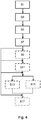
- Fig. 4 shows a schematic representation of the method according to the invention of an exemplary embodiment using a device 100 which is connected to a blood treatment device 200 according to the invention or is part thereof.
- the method comprises the detection of a predetermined fill level value H1 in the container 1 of the device 100.
- the fluid 11 can be water, but is not limited to water.
- the fluid 11 can be a mixture of liquids.
- the method includes starting the filling of the container 1 when the filling level is below the predetermined filling level value H1.
- the filling of the container 1 can include, for example, the opening of a shut-off valve 131 of the inlet 9.
- the process of filling and opening the valve 131 requires that a filling of the balancing chamber 19 was stopped or ended beforehand. During a previous filling of the balancing chamber 19, in turn, the inlet 9 or the valve 131 must have been closed.
- step S5 the method comprises the heating of the fluid 11 in the heating container 3, or its start when the filling level of the container 1 reaches the predetermined filling level value H1.
- step S7 the method includes optional monitoring of the fill level of the container 1. If the fill level falls below the predetermined fill level value H1, for example by removing water to fill the dialysis fluid circuit, the heating process is stopped or interrupted. The heating process can also be stopped completely, i.e. finally ended.
- the method can include the optional step S9, in which the heating process is only started when the fill level initially falls below the predetermined fill level value H1 and then, after filling the container 1, reaches the predetermined fill level value H1.
- the method can include the optional step S11, in which the water in the water inlet system is degassed by means of a degassing chamber 35 for degassing the water 11 and / or by means of an air separation chamber 23 for separating air that is in the water.
- the method can include the optional step S13, the water 11 from the inlet 9 being stored in a previous step in a fluid reservoir 7, from the fluid reservoir 7 by means of an overflow into the container 1 to determine the fill level of the water 11 flows or is promoted.
- step 13 the method according to the invention can contain the optional step S15 in a further embodiment.
- step 15 water 11 from the inlet 9 is first stored in the fluid reservoir 7, then the water 11 flows into the heating container 3 and then from the heating container 3 into the container 1 by means of an overflow.
- the method can include the optional step S17, in which water 11 is additionally heated by means of a heat exchanger 17, dialysate from the balancing chamber 19 flowing through the heat exchanger 17.
Description
Die vorliegende Erfindung betrifft ein Verfahren zum Regeln und/oder Überwachen einer Heizvorrichtung zum Erwärmen eines Fluids gemäß Anspruch 1. Sie betrifft ferner eine Steuer- oder Regelvorrichtung gemäß Anspruch 10 sowie eine Blutbehandlungsvorrichtung gemäß Anspruch 11. Des Weiteren betrifft die vorliegende Erfindung ein digitales Speichermedium gemäß Anspruch 14 sowie, ein Computerprogramm-Produkt gemäß Anspruch 15.The present invention relates to a method for regulating and / or monitoring a heating device for heating a fluid according to
Dialysierflüssigkeiten für Blutbehandlungsvorrichtungen können auf unterschiedliche Art und Weise bereitgestellt werden, bevor sie einem Dialysierflüssigkeitskreislauf zugeführt werden. Beispielsweise kann aus einem externen Wasserversorgungssystem Wasser abgeführt und für den Dialysierflüssigkeitskreislauf aufbereitet werden. Die Aufbereitung kann in einem Vorlaufkreislauf oder in einem Wassereingangssystem durchgeführt werden, in dem verschiedene Aufbereitungsschritte zur Herstellung der Dialysierflüssigkeit durchgeführt werden. Das Wasser oder die fertige Dialysierflüssigkeit wird anschließend mittels einer Heizvorrichtung erwärmt und dem Dialysierkreislauf, in welchen ein Blutfilter oder Dialysator integriert ist, zugeführt. Die
Eine Aufgabe der vorliegenden Erfindung ist es, ein Verfahren zum Steuern, Regeln und/oder Überwachen einer Heizvorrichtung zum Erwärmen eines Fluids für eine Blutbehandlung anzugeben. Zudem sollen geeignete Vorrichtungen, ein geeignetes digitales Speichermedium und ein geeignetes Computerprogramm-Produkt angegeben werden.It is an object of the present invention to provide a method for controlling, regulating and / or monitoring a heating device for heating a fluid for a blood treatment. In addition, suitable devices, a suitable digital storage medium and a suitable computer program product should be specified.
Die erfindungsgemäße Aufgabe kann durch ein Verfahren mit den Merkmalen des Anspruchs 1 gelöst werden. Sie kann ferner gelöst werden mittels der Steuer- oder Regelvorrichtung mit den Merkmalen des Anspruchs 10 sowie mittels einer Blutbehandlungsvorrichtung mit den Merkmalen des Anspruchs 11. Sie kann zudem gelöst werden mittels des digitalen Speichermediums mit den Merkmalen des Anspruchs 14 sowie mittels des Computerprogramm-Produkts mit den Merkmalen des Anspruchs 15.The object according to the invention can be achieved by a method having the features of
Erfindungsgemäß wird somit ein Verfahren zum Steuern oder Regeln (die Begriffe "Steuern" und "Regeln" sind hierin alternativ oder austauschbar zu verstehen; beide Modi sind erfindungsgemäß umfasst) und/oder Überwachen einer Heizvorrichtung zum Erwärmen eines Fluids vorgeschlagen, welches insbesondere über einen Zulauf in einen Vorlauf eines Dialysierflüssigkeitskreislaufs fließt oder geflossen ist. Das Fluid kann Wasser sein, das beispielsweise aus einer externen Wasserversorgungsanlage geführt wird. Der Dialysierflüssigkeitskreislauf ist Teil einer Blutbehandlungsvorrichtung oder hiermit verbunden. Der Dialysierflüssigkeitskreislauf weist einen Behälter zur Aufnahme des Fluids und einen Heizbehälter zum Erwärmen des Fluids auf, wobei der Heizbehälter in Fluidkommunikation mit dem Behälter steht.According to the invention, a method for controlling or regulating (the terms “controlling” and “regulating” are to be understood alternatively or interchangeably here; both modes are encompassed according to the invention) and / or monitoring a heating device for heating a fluid is proposed, in particular via an inlet flows or has flowed into a feed line of a dialysis fluid circuit. The fluid can be water that is fed, for example, from an external water supply system. The dialysis fluid circuit is part of a blood treatment device or is connected to it. The dialysis fluid circuit has a container for receiving the fluid and a heating container for heating the fluid, the heating container being in fluid communication with the container.
Das Verfahren umfasst ein Starten eines Heizvorgangs zum Erwärmen des Fluids im Heizbehälter nur dann, wenn der Füllstand des Behälters mittels insbesondere direktem oder indirektem, Zuflusses einen vorbestimmten Füllstandswert (oder vorbestimmten Füllstand) wenigstens einmal, oder erstmalig, erreicht.The method includes starting a heating process for heating the fluid in the heating container only when the filling level of the container reaches a predetermined filling level value (or predetermined filling level) at least once or for the first time by means of in particular direct or indirect inflow.
Manche oder alle der Schritte des erfindungsgemäßen Verfahrens können automatisiert, etwa veranlasst durch eine entsprechend programmierte oder konfigurierte, Steuervorrichtung oder Regelvorrichtung (die Begriffe "Steuervorrichtung" und "Regelvorrichtung" sind hierin alternativ oder austauschbar zu verstehen) gemäß der vorliegenden Erfindung, ablaufen. Die Steuervorrichtung kann programmiert und/oder konfiguriert sein, die Schritte des erfindungsgemäßen Verfahrens einzuleiten, auszuführen oder zu bewirken.Some or all of the steps of the method according to the invention can be automated, for example initiated by an appropriately programmed or configured control device or regulating device (the terms "control device" and "regulating device" are to be understood here as alternatives or interchangeably) according to the present invention. The control device can be programmed and / or configured to initiate, execute or effect the steps of the method according to the invention.
Die erfindungsgemäße Blutbehandlungsvorrichtung weist wenigstens eine erfindungsgemäße Steuervorrichtung auf oder ist hiermit in Signalkommunikation verbunden.The blood treatment device according to the invention has at least one control device according to the invention or is connected to it in signal communication.
Ein erfindungsgemäßes digitales, insbesondere nicht-flüchtiges, Speichermedium, insbesondere in Form eines maschinenlesbaren Trägers, insbesondere in Form einer Diskette, CD, DVD oder EPROM, insbesondere mit elektronisch oder optisch auslesbaren Steuersignalen, kann derart mit einem programmierbaren Computersystem zusammenwirken, dass die maschinellen Schritte eines erfindungsgemäßen Verfahrens veranlasst werden.A digital, in particular non-volatile, storage medium according to the invention, in particular in the form of a machine-readable carrier, in particular in the form of a diskette, CD, DVD or EPROM, in particular with electronically or optically readable control signals, can interact with a programmable computer system in such a way that the machine steps a method according to the invention can be initiated.
Ein erfindungsgemäßes Computerprogramm-Produkt weist einen volatilen, flüchtigen oder auf einem maschinenlesbaren Träger gespeicherten Programmcode oder eine Signalwelle zur Veranlassung der maschinellen Schritte des erfindungsgemäßen Verfahrens, wenn das Computerprogramm-Produkt auf einem Rechner abläuft, auf. Unter einem Computerprogramm-Produkt kann erfindungsgemäß beispielsweise ein auf einem Träger gespeichertes Computerprogramm, ein Embedded System als umfassendes System mit einem Computerprogramm (z. B. elektronisches Gerät mit einem Computerprogramm), ein Netzwerk von computerimplementierten Computerprogrammen (z. B. Client/Serversystem, Cloud Computing System, etc.), oder ein Computer, auf dem ein Computerprogramm geladen ist, abläuft, gespeichert ist, ausgeführt oder entwickelt wird, verstanden werden.A computer program product according to the invention has a volatile, volatile program code or a signal wave stored on a machine-readable carrier to initiate the machine steps of the method according to the invention when the computer program product runs on a computer. According to the invention, a computer program product can be, for example, a computer program stored on a carrier, an embedded system as a comprehensive system with a computer program (e.g. electronic device with a computer program), a network of computer-implemented computer programs (e.g. client / server system, Cloud Computing System, etc.), or a computer on which a computer program is loaded, runs, is stored, executed or developed.
Der Begriff "maschinenlesbarer Träger", wie er hierin verwendet wird, bezeichnet in manchen beispielhaften Ausführungsformen der vorliegenden Erfindung einen Träger, der von Software und/oder Hardware interpretierbare Daten oder Informationen enthält. Der Träger kann ein Datenträger, wie eine Diskette, eine CD, DVD, ein USB-Stick, eine Flashcard, eine SD-Karte und dergleichen sein.The term “machine-readable carrier” as used herein denotes in some exemplary embodiments of the present invention a carrier that contains data or information that can be interpreted by software and / or hardware. The carrier can be a data carrier such as a floppy disk, a CD, DVD, a USB stick, a flash card, an SD card and the like.
Ein offenbartes, nicht beanspruchtes Computerprogramm weist einen Programmcode auf zur Veranlassung der maschinellen Schritte des erfindungsgemäßen Verfahrens, wenn das Computerprogramm auf einem Computer abläuft. Unter einem Computerprogramm kann erfindungsgemäß beispielsweise ein physikalisches, vertriebsfähiges Software-Produkt verstanden werden, welches ein Programm aufweist.A disclosed, not claimed computer program has a program code to initiate the machine steps of the method according to the invention when the computer program runs on a computer. According to the invention, a computer program can be understood to mean, for example, a physical, marketable software product which has a program.
Für das erfindungsgemäße digitale Speichermedium, das erfindungsgemäße Computerprogramm-Produkt und das offenbarte, nicht beanspruchte Computerprogramm gilt, dass alle, einige oder manche der maschinell durchgeführten Schritte des erfindungsgemäßen Verfahrens veranlasst werden. Dies gilt insbesondere im Zusammenwirken mit einer erfindungsgemäßen Blutbehandlungsvorrichtung wie beschrieben.For the digital storage medium according to the invention, the computer program product according to the invention and the disclosed, not claimed computer program, all, some or some of the machine-carried out steps of the method according to the invention are initiated. This applies in particular in conjunction with a blood treatment device according to the invention as described.
Bei allen Ausführungen ist der Gebrauch des Ausdrucks "kann sein" bzw. "kann haben" usw. synonym zu "ist insbesondere" bzw. "hat insbesondere" usw. zu verstehen und/oder soll eine weitere beispielhafte, erfindungsgemäße Ausführungsform erläutern.In all embodiments, the use of the expression “can be” or “can have” etc. is to be understood as synonymous with “is in particular” or “has in particular” etc. and / or is intended to explain a further exemplary embodiment according to the invention.
Erfindungsgemäße Ausführungsformen können eines oder mehrere der vorstehend oder im Folgenden genannten Merkmale in beliebiger Kombination aufweisen, sofern eine solche Kombination nicht für den Fachmann erkennbar technisch unmöglich ist. Erfindungsgemäße Ausführungsformen sind ferner auch Gegenstand der Unteransprüche.Embodiments according to the invention can have one or more of the features mentioned above or below in any combination, provided that one such a combination is technically impossible, not recognizable to the person skilled in the art. Embodiments according to the invention are also the subject of the subclaims.
Wann immer hierin Zahlenworte genannt werden, so versteht der Fachmann diese als Angabe einer zahlenmäßig unteren Grenze. Sofern dies zu keinem für den Fachmann erkennbaren Widerspruch führt, liest der Fachmann daher beispielsweise bei der Angabe "ein" oder "einem" stets "wenigstens ein" oder "wenigstens einem" mit. Dieses Verständnis ist ebenso von der vorliegenden Erfindung mit umfasst wie die Auslegung, dass ein Zahlenwort wie beispielsweise "ein" alternativ als "genau ein" gemeint sein kann, wo immer dies für den Fachmann erkennbar technisch möglich ist. Beides ist von der vorliegenden Erfindung umfasst und gilt für alle hierin verwendeten Zahlenworte.Whenever numerical words are mentioned here, the person skilled in the art understands them to indicate a numerically lower limit. Insofar as this does not lead to a contradiction that is recognizable to the person skilled in the art, the person skilled in the art therefore always reads “at least one” or “at least one” with the specification “a” or “an”. This understanding is also encompassed by the present invention, as is the interpretation that a numerical word such as, for example, “an” can alternatively be meant as “exactly one”, wherever this is technically possible for the person skilled in the art. Both are encompassed by the present invention and apply to all numerical words used herein.
Die Angaben "oben" und "unten" sind hierin bei Zweifel des Fachmanns als absolute oder relative Raumangaben zu verstehen, welche sich auf die Ausrichtung des betreffenden Bauteils während seines üblichen Gebrauchs beziehen.If the person skilled in the art has doubts, the information "above" and "below" are to be understood here as absolute or relative spatial information relating to the orientation of the component in question during its normal use.
In manchen beispielhaften, erfindungsgemäßen Ausführungsformen ist der Vorlauf zum Dialysierflüssigkeitskreislauf ein Wasserkreislauf oder ein Wassereingangssystem. Der Vorlauf kann als hydraulisches System bezeichnet werden. Der Zulauf kann ein Zulauf aus einem externen Wasserversorgungssystem oder einem Wasserleitungssystem sein. Der Zulauf kann ein Wassereinlauf sein.In some exemplary embodiments according to the invention, the flow to the dialysis fluid circuit is a water circuit or a water inlet system. The flow can be called a hydraulic system. The inlet can be an inlet from an external water supply system or a water pipe system. The inlet can be a water inlet.
Im Folgenden wird der Begriff "Fluid" synonym zum Begriff "Wasser" verwendet, ohne dass das Fluid hierdurch jedoch auf Wasser beschränkt werden soll. Das Fluid kann ebenso ein anderes Medium und insbesondere eine andere Flüssigkeit sein, sofern für einen Vorlauf zum Dialysierflüssigkeitskreislauf geeignet.In the following, the term “fluid” is used synonymously with the term “water”, without, however, intended to restrict the fluid to water. The fluid can also be a different medium and in particular a different liquid, provided that it is suitable for a flow to the dialysis fluid circuit.
In manchen beispielhaften, erfindungsgemäßen Ausführungsformen wird der vorbestimmte Füllstandswert erreicht, wenn sich der Füllstand von einem Füllstand, der einem unterhalb des vorbestimmten Füllstandwerts liegenden Füllstandswert entspricht, bei welchem der Behälter vergleichsweise leer ist, zu einem Füllstand übergeht, bei dem der Behälter vergleichsweise voll ist und dem ein auf oder oberhalb des vorbestimmten Füllstandswert liegender Füllstandswert entspricht.In some exemplary embodiments according to the invention, the predetermined fill level value is reached when the fill level changes from a fill level that corresponds to a fill level value below the predetermined fill level value at which the container is comparatively empty to a fill level at which the container is comparatively full and to which corresponds to a level value lying at or above the predetermined level value.
In manchen beispielhaften, erfindungsgemäßen Ausführungsformen ist der vorbestimmte Füllstandswert ein Grenzwert.In some exemplary embodiments according to the invention, the predetermined fill level value is a limit value.
In manchen beispielhaften, erfindungsgemäßen Ausführungsformen gibt der Füllstandswert, wenn er von "unten kommend" erreicht ist, an, dass der Behälter vollständig befüllt ist. Alternativ wird ungeachtet des tatsächlich Füllstandes des Behälters davon ausgegangen, dass der Behälter bei Erreichen des vorbestimmten Füllstandswerts ausreichend oder vollständig befüllt ist.In some exemplary embodiments according to the invention, the fill level value, when it is reached “coming from below”, indicates that the container is completely filled. Alternatively, regardless of the actual fill level of the container, it is assumed that the container is sufficiently or completely filled when the predetermined fill level value is reached.
In manchen beispielhaften, erfindungsgemäßen Ausführungsformen gibt der Füllstandswert, wenn er von "oben kommend" erreicht ist, an, dass der Behälter leer ist. Alternativ wird ungeachtet des tatsächlich Füllstandes des Behälters davon ausgegangen, dass der Behälter bei Unterschreiten des vorbestimmten Füllstandswerts nicht ausreichend befüllt ist.In some exemplary embodiments according to the invention, the fill level value, when it is reached “coming from above”, indicates that the container is empty. Alternatively, regardless of the actual fill level of the container, it is assumed that the container is not sufficiently filled when the value falls below the predetermined fill level.
"Leer" und "befüllt" sind nicht darauf beschränkt zu verstehen, dass sich etwa bei leerem Behälter keinerlei Fluid mehr in diesem befindet bzw. kein weiteres Fluid in den Behälter passen würde.“Empty” and “filled” are not to be understood as being restricted to the fact that, for example, when the container is empty, there is no longer any fluid in it or that no further fluid would fit into the container.
Ein Erreichen oder Unterschreiten des vorbestimmten Füllstandwerts kann vielmehr als eine Information für die Steuervorrichtung verstanden werden, die auf eine solche Information z. B. mit dem Öffnen oder Schließen eines Ventils zu einem Zulauf reagieren kann.Rather, reaching or falling below the predetermined level value can be understood as information for the control device, which is based on such information z. B. can react to an inlet by opening or closing a valve.
In manchen beispielhaften, erfindungsgemäßen Ausführungsformen gibt der Füllstandswert an, dass der Behälter vollständig befüllt ist. Alternativ wird ungeachtet des tatsächlich Füllstandes des Behälters davon ausgegangen, dass der Behälter bei Erreichen des vorbestimmten Füllstandswerts ausreichend oder vollständig befüllt ist.In some exemplary embodiments according to the invention, the fill level value indicates that the container is completely filled. Alternatively, regardless of the actual fill level of the container, it is assumed that the container is sufficiently or completely filled when the predetermined fill level value is reached.
In manchen beispielhaften, erfindungsgemäßen Ausführungsformen wird der Heizvorgang erst dann gestartet, wenn der Füllstand den vorbestimmten Füllstandswert mehrfach, insbesondere zweimal, dreimal, viermal oder fünfmal, erreicht hat.In some exemplary embodiments according to the invention, the heating process is only started when the fill level has reached the predetermined fill level value several times, in particular twice, three times, four times or five times.
In manchen beispielhaften, erfindungsgemäßen Ausführungsformen beginnt das Starten des Heizvorgangs zum Erwärmen des Fluids im Heizbehälter nur dann, nachdem ein Zufluss in den Vorlauf und/oder ein Ablauf aus dem Behälter unterbunden wurde oder nicht erfolgte, beispielsweise nach einem Stopp der Dialysevorrichtung oder des Zulaufs, z. B. wegen eines Alarms.In some exemplary embodiments according to the invention, the starting of the heating process for heating the fluid in the heating container begins only after an inflow into the flow and / or an outflow from the container has been or has not occurred, for example after the dialysis machine or the inflow has been stopped, z. B. because of an alarm.
In manchen beispielhaften, erfindungsgemäßen Ausführungsformen beginnt das Starten des Heizvorgangs zum Erwärmen des Fluids im Heizbehälter nur, falls ferner (oder sobald ferner) ein Fluid aus einer Bilanzkammer der Blutbehandlungsvorrichtung herausströmt. Dies gilt insbesondere, nachdem der Fluss aus der Bilanzkammer unterbunden wurde oder nicht erfolgte.In some exemplary embodiments according to the invention, the starting of the heating process for heating the fluid in the heating container only begins if furthermore (or as soon as furthermore) a fluid flows out of a balance chamber of the blood treatment device. This applies in particular after the flow from the balancing chamber has been stopped or has not occurred.
Mit einer Bilanzkammer wird immer ein vorbestimmtes Volumen gepumpt, wobei zwischen Phasen, in welchen die Volumina gepumpt werden, Ventilschaltphasen liegen, in denen die Ventile der Bilanzkammer umgeschaltet werden. Während der Ventilschaltphasen kann kein Fluss vorliegen. Diese Ventilschaltphasen gehören im Sinne dieser Beschreibung dennoch zu den Phasen, in denen ein Fluss vorliegt. Bei einer kontinuierlich arbeitenden Bilanzkammer liegt mit anderen Worten gemäß dieser Beschreibung auch während der Ventilschaltphasen ein Fluss vor, und das Starten der Heizung wird nicht in diesen Ventilschaltphasen gemäß des erfindungsgemäßen Verfahrens gesteuert, wenn es dadurch zu einem kurzzeitigen Stoppen des Flusses kommt. In diesem Sinne sind Phasen, die auf Grund der Konstruktion bzw. Ansteuerung der Pumpvorrichtung oder der Bilanzkammer, mit der ein diskontinuierlicher beziehungsweise pulsatiler Fluss generiert wird, ebenfalls als Flussphasen zu verstehen, also nicht als Phasen, in denen der Fluss aus der Bilanzkammer unterbunden gewesen wäre.A predetermined volume is always pumped with a balancing chamber, valve switching phases in which the valves of the balancing chamber are switched between phases in which the volumes are pumped. There can be no flow during the valve switching phases. In the context of this description, these valve switching phases nevertheless belong to the phases in which there is a flow. In other words, in a continuously operating balance chamber, according to this description, there is also a flow during the valve switching phases, and the start of the heating is not controlled in these valve switching phases according to the method according to the invention if this results in a brief stop of the flow. In this sense, phases that are due to the construction or control of the pumping device or the balancing chamber, with which a discontinuous or pulsatile flow is generated, are also to be understood as flow phases, i.e. not as phases in which the flow from the balancing chamber was prevented were.
In manchen beispielhaften, erfindungsgemäßen Ausführungsformen ist der Heizbehälter stromauf oder stromab des Behälters angeordnet, beide Behälter stehen mittels einer oder mehrerer Verbindungsleitungen in Fluidverbindung miteinander. Der Behälter und der Heizbehälter können eine Einheit miteinander bilden und unmittelbar miteinander verbunden sein. Der Behälter und der Heizbehälter können in einer Einheit oder in einem Gehäuse angeordnet sein und beispielsweise mittels einer Trennwand und/oder einem Überlaufsystem und/oder einem Schlauchsystem oder einem Rohrsystem miteinander in Fluidverbindung stehen.In some exemplary embodiments according to the invention, the heating container is arranged upstream or downstream of the container, and the two containers are in fluid connection with one another by means of one or more connecting lines. The container and the heating container can form a unit with one another and be directly connected to one another. The container and the heating container can be arranged in a unit or in a housing and can be in fluid connection with one another, for example by means of a partition and / or an overflow system and / or a hose system or a pipe system.
In manchen beispielhaften, erfindungsgemäßen Ausführungsformen ist das Starten des Heizvorgangs ein Verstärken der Heizanstrengung, ausgehend von einem niedrigen Heizniveau, bei welchem die Heizvorrichtung auch ohne ausreichenden Füllstand oder Fluid im Heizbehälter keinen Schaden infolge eines zu starken Erwärmens und beispielsweise einer Schädigung des Heizbehälters, in dem das Fluid bei normalem Betrieb fließt und mittels der Heizvorrichtung aufgeheizt wird oder eines "Durchbrennens" eines Heizstabs nimmt. Bei diesen Ausführungsformen kann das Starten der Heizaktivität als ein Verlassen beispielsweise eines "Stand by"-Heizmodus zu verstehen sein.In some exemplary embodiments according to the invention, starting the heating process is an intensification of the heating effort, starting from a low heating level at which the heating device does not suffer any damage due to excessive heating and, for example, damage to the heating container, even without sufficient fill level or fluid in the heating container the fluid flows during normal operation and is heated up by means of the heating device or a "burn through" of a heating rod. In these embodiments, the starting of the heating activity can be understood as exiting, for example, a “stand-by” heating mode.
In manchen beispielhaften, erfindungsgemäßen Ausführungsformen kann es sich bei der Heizvorrichtung um einen Heizstab handeln. Dieser Heizstab kann von unten oder von oben in den Heizbehälter eingeführt sein. Der Heizstab kann derart aufgebaut sein, dass er zwei Bereiche aufweist. Im ersten Bereich ist das das Heizen erzeugende Element, beispielsweise eine Heizspirale, angeordnet, und im zweiten Bereich ist dieses Element nach außen kontaktiert. Der erste Bereich ist dabei an dem der Kontaktierung entfernten Ende des Heizstabs angeordnet. Bei einem von unten eingeführten Heizstab führt ein Absenken des Flüssigkeitspegels unter die Höhe des Heizstabs beziehungsweise das Ausbilden eines Luftpolsters am oberen Ende des Heizstabs unmittelbar dazu, dass ein stark aufgeheizter Bereich des ersten Bereichs des Heizstabes nicht von Flüssigkeit bedeckt ist und damit schnell oder schneller zu einer potentiellen Schädigung durch Überhitzen. Bei einem von oben eingeführten Heizstab wird zunächst der zweite Bereich vom Fluid freigegeben, so dass hier ein Luftpolster im Heizbehälter weniger rasch zum Problem einer Schädigung durch ein Überheizen führen mag.In some exemplary embodiments according to the invention, the heating device can be a heating rod. This heating rod can be inserted into the heating container from below or from above. The heating rod can be constructed in such a way that it has two areas. The element generating the heating, for example a heating coil, is arranged in the first area, and this element is in contact with the outside in the second area. The first area is arranged at the end of the heating rod remote from the contact. In the case of a heating rod inserted from below, lowering the liquid level below the height of the heating rod or the formation of an air cushion at the upper end of the heating rod leads directly to the fact that a strongly heated area of the first area of the heating rod is not covered by liquid and is therefore supplied quickly or more quickly potential damage from overheating. In the case of a heating rod inserted from above, the second area is initially released from the fluid, so that here an air cushion in the heating container may less quickly lead to the problem of damage due to overheating.
In manchen beispielhaften, erfindungsgemäßen Ausführungsformen ist das Anhalten des Heizvorgangs ein Verringern der Heizanstrengung, ausgehend von einem höheren Heizniveau, und/oder beispielsweise das Überführen der Heizaktivität in einen Heizmodus, in welchem die Heizvorrichtung auch ohne ausreichenden Füllstand oder Fluid im Heizbehälter keinen Schaden infolge eines zu starken Erwärmens und beispielsweise eines "Durchbrennens" eines Heizstabs oder eines Überhitzens nimmt. Bei diesen Ausführungsformen kann das Anhalten der Heizaktivität als ein Überführen beispielsweise in einen "Stand by"-Heizmodus zu verstehen sein.In some exemplary embodiments according to the invention, stopping the heating process is a reduction in the heating effort, starting from a higher heating level, and / or, for example, transferring the heating activity to a heating mode in which the heating device does not suffer any damage as a result of a excessive heating and for example "burnout" of a heating element or overheating takes place. In these embodiments, the stopping of the heating activity can be understood as a transfer to a “stand-by” heating mode, for example.
In manchen beispielhaften, erfindungsgemäßen Ausführungsformen wird der Heizvorgang erst dann gestartet, wenn der Füllstand zunächst unter den vorbestimmten Füllstandswert gefallen ist und anschließend, d. h. nach einem Befüllen des Behälters, den vorbestimmten Füllstandswert erreicht oder überschreitet. Anders ausgedrückt muss der Füllstand in diesen Ausführungsformen zunächst bis auf den einen Füllstand abgefallen sein, welcher beispielsweise einen leeren oder nicht mehr ausreichend gefüllten Behälter anzeigt. Anschließend, also erst nachdem der Behälter zunächst nicht ausreichend befüllt war, füllt sich der Behälter bis wenigstens zum vorbestimmten Füllstand oder Füllstandswert und erst nach dessen Erreichen wird der Heizvorgang gestartet. Mit diesem Ablauf kann sichergestellt werden, dass der Heizbehälter tatsächlich befüllt sein muss und ein Starten des Heizvorgangs mit einem leeren Heizbehälter ausgeschlossen werden kann. Dies gilt insbesondere dann, wenn der Heizbehälter dem Behälter vorgeschaltet ist. In diesem Fall kann davon ausgegangen werden, dass der Behälter nur dann gefüllt sein kann, wenn der Heizbehälter ebenfalls gefüllt ist. Damit wird sichergestellt, dass der Heizvorgang nur bei ausreichend befülltem Heizbehälter gestartet wird.In some exemplary embodiments according to the invention, the heating process is only started when the fill level has initially fallen below the predetermined fill level value and then, ie after the container has been filled, reaches or exceeds the predetermined fill level value. In other words, the fill level in these embodiments must first have dropped to the one fill level which, for example, indicates an empty or insufficiently filled container. Subsequently, that is to say only after the container was initially insufficiently filled, the container fills up to at least the predetermined fill level or fill level value and the heating process is only started after this has been reached. This process ensures that the heating container is actually filled must and starting the heating process with an empty heating container can be excluded. This applies in particular when the heating container is connected upstream of the container. In this case it can be assumed that the container can only be filled when the heating container is also filled. This ensures that the heating process is only started when the heating container is sufficiently full.
In manchen beispielhaften, erfindungsgemäßen Ausführungsformen wird der Füllstand des Behälters mittels eines mechanischen Füllstandsmessers, eines Leitfähigkeitssensors, eines optischen Sensors oder einer beliebigen Kombination hiervon bestimmt.In some exemplary embodiments according to the invention, the fill level of the container is determined by means of a mechanical fill level meter, a conductivity sensor, an optical sensor or any combination thereof.
Ein mechanischer Füllstandsmesser ist beispielsweise ein Schwimmer, der sich mit einem Füllstandspegel mitbewegt. Mit einem an den Schwimmer angeschlossenen oder verbundenen Positionssensor kann der Füllstand als elektrisches Signal in eine Regelvorrichtung oder Steuervorrichtung weitergeführt werden. Der mechanische Füllstandsmesser kann als mechanischer Sensor bezeichnet werden.A mechanical fill level meter is, for example, a float that moves with a fill level. With a position sensor connected or connected to the float, the level can be passed on as an electrical signal to a regulating device or control device. The mechanical level meter can be referred to as a mechanical sensor.
Der Füllstandssensor kann einen Schalter aufweisen, beispielsweise einen Schwimmerschalter. Ist der Schalter geöffnet, gilt der Behälter als gefüllt und/oder der vorbestimmte Füllstandswert erreicht. Ist der Schalter geschlossen, so wird der Behälter nachgefüllt. Damit wird sichergestellt, dass eine gewisse Füllmenge nicht unterschritten wird mit hiermit verbundenen Vorteilen, dass die eine erforderliche Reaktionszeit bietet, und damit der Heizbehälter nicht leer läuft. Eine mit dem Schalter verbundene Schaltung kann ausgestaltet sein, um eine gewisse Hysterese zu berücksichtigen, damit bei einem bewegten Wasserfüllstand nicht auch dann nachgefüllt wird, wenn dies noch nicht erforderlich ist.The level sensor can have a switch, for example a float switch. If the switch is open, the container is considered full and / or the predetermined level has been reached. If the switch is closed, the container is refilled. This ensures that the filling quantity does not fall below a certain level, with the associated advantages that it offers a necessary reaction time and that the heating container does not run empty. A circuit connected to the switch can be designed to take into account a certain hysteresis so that when the water level is moving, refilling is not carried out when this is not yet necessary.
In manchen beispielhaften, erfindungsgemäßen Ausführungsformen wird das Fluid aus dem Zulauf zunächst in einem Fluidreservoir gespeichert. Anschließend fließt das Fluid in den Heizbehälter und daran anschließend mittels Überlaufs aus dem Heizbehälter in den Behälter.In some exemplary embodiments according to the invention, the fluid from the inlet is first stored in a fluid reservoir. The fluid then flows into the heating container and then by means of an overflow from the heating container into the container.
In manchen beispielhaften, erfindungsgemäßen Ausführungsformen wird das Fluid zusätzlich mittels eines Wärmetauschers erwärmt. Der Wärmetauscher kann Dialysat (also verbrauchte oder aus dem Dialysator abgeführte Dialysierflüssigkeit) aus dem Dialysierflüssigkeitskreislauf führen und Wärme des Dialysats auf das Fluid übertragen. Das Dialysat kann anschließend stromab des Wärmetauschers entsorgt werden.In some exemplary embodiments according to the invention, the fluid is additionally heated by means of a heat exchanger. The heat exchanger can dialysate (that is, dialysate used or discharged from the dialyzer) from the Lead the dialysis fluid circuit and transfer heat from the dialysate to the fluid. The dialysate can then be disposed of downstream of the heat exchanger.
In manchen beispielhaften, erfindungsgemäßen Ausführungsformen wird Fluid, das mittels der Heizvorrichtung und/oder dem Wärmetauscher erwärmt wurde, mittels einer Bilanzkammer aus dem Vorlauf des Dialysierflüssigkeitskreislaufs in den Dialysierflüssigkeitskreislauf gefördert.In some exemplary embodiments according to the invention, fluid that has been heated by means of the heating device and / or the heat exchanger is conveyed from the flow of the dialysis fluid circuit into the dialysis fluid circuit by means of a balancing chamber.
In manchen beispielhaften, erfindungsgemäßen Ausführungsformen weist der Heizbehälter einen Temperatursensor auf, konfiguriert zum Messen der Temperatur des Fluids im Heizbehälter.In some exemplary embodiments according to the invention, the heating container has a temperature sensor configured to measure the temperature of the fluid in the heating container.
In manchen beispielhaften, erfindungsgemäßen Ausführungsformen muss zum Starten des Heizvorgangs der Füllstand des Behälters den vorbestimmten Füllstandswert über einen vorbestimmten Zeitraum T1 hinweg angenommen oder überschritten haben, insbesondere in einem Rezirkulationsmodus.In some exemplary embodiments according to the invention, in order to start the heating process, the filling level of the container must have assumed or exceeded the predetermined filling level value over a predetermined period of time T1, in particular in a recirculation mode.
Das Starten der Heizung nach einer vorbestimmten Zeitdauer kann insbesondere in einem Rezirkulationsmodus aktiviert sein. Die Blutbehandlungsvorrichtung kann in verschiedenen Modi betreibbar sein, beispielsweise einem Behandlungsmodus und einem Rezirkulationsmodus. In dem Behandlungsmodus wird Flüssigkeit dem Hydrauliksystem, den Vorlauf und den Dialysatkreislauf aufweisend, zugeführt und abgeführt, während im Rezirkulationsmodus die Flüssigkeit zirkuliert, ohne dass dem System Flüssigkeit zugeführt wurde oder entnommen wird. Dadurch bleibt der Pegel im Behälter weitestgehend konstant, weshalb der Füllstandsmesser oder Schwimmer einen "gefüllten" Behälter angibt. Dieser Rezirkulationsmodus kann beispielweise zumindest während eines Reinigungsmodus, insbesondere eines Heißreinigens, aktiviert sein, in dem die Heizvorrichtung gestartet werden muss, auch wenn der Füllstandsmesser oder Schwimmer keine Bewegung macht, die einen Füllvorgang des Behälters anzeigen würde. Um bei gleichbleibendem Füllstand ein Starten der Heizung zu ermöglichen, wird in diesem Modus obiges Starten nach Ablauf einer vorbestimmten Zeitdauer, während welcher der vorbestimmte Füllstandswert durchgehend erreicht war, erlaubt.Starting the heating after a predetermined period of time can in particular be activated in a recirculation mode. The blood treatment device can be operated in different modes, for example a treatment mode and a recirculation mode. In the treatment mode, fluid is supplied to and removed from the hydraulic system, including the flow and the dialysate circuit, while in the recirculation mode, the fluid circulates without fluid being supplied to or withdrawn from the system. As a result, the level in the container remains largely constant, which is why the level meter or float indicates that the container is "full". This recirculation mode can be activated, for example, at least during a cleaning mode, in particular hot cleaning, in which the heating device must be started, even if the level meter or float does not make any movement that would indicate a filling process of the container. In order to enable the heating to be started while the fill level remains the same, the above starting is permitted in this mode after a predetermined period of time during which the predetermined fill level value was continuously reached.
In manchen beispielhaften, erfindungsgemäßen Ausführungsformen wird wenigstens einer der folgenden Schritte mittels der Steuervorrichtung gesteuert oder geregelt: das Starten oder Beenden des Heizvorgangs im Heizbehälter; das Überwachen des Füllstands im Behälter oder des Füllstandsensors; und das Öffnen oder Schließen eines Absperrventils zum Befüllen des Fluidreservoirs und/oder des Behälters mittels des Zulaufs.In some exemplary embodiments according to the invention, at least one of the following steps is controlled or regulated by means of the control device: starting or ending the heating process in the heating container; monitoring the level in the container or the level sensor; and opening or closing one Shut-off valve for filling the fluid reservoir and / or the container by means of the inlet.
In manchen beispielhaften, erfindungsgemäßen Ausführungsformen umfasst die Blutbehandlungsvorrichtung wenigstens den Behälter, eine Einrichtung zum Erkennen, ob der vorbestimmte Füllstandswert des Behälters erreicht ist, einen mit dem Behälter in Fluidverbindung stehenden Heizbehälter mit einer Heizvorrichtung zum Erwärmen des Fluids und eine Einrichtung zum Weiterleiten des Fluids in den Dialysierflüssigkeitskreislauf der Blutbehandlungsvorrichtung.In some exemplary embodiments according to the invention, the blood treatment device comprises at least the container, a device for detecting whether the predetermined fill level value of the container has been reached, a heating container in fluid communication with the container with a heating device for heating the fluid and a device for conveying the fluid in the dialysis fluid circuit of the blood treatment device.
In manchen beispielhaften, erfindungsgemäßen Ausführungsformen weist die Einrichtung zum Befüllen oder Weiterleiten des Fluids in den Dialysierflüssigkeitskreislauf eine Bilanzkammer auf oder ist als solche ausgestaltet.In some exemplary embodiments according to the invention, the device for filling or forwarding the fluid into the dialysis fluid circuit has a balancing chamber or is designed as such.
In manchen beispielhaften, erfindungsgemäßen Ausführungsformen weist die Blutbehandlungsvorrichtung ein Reservoir auf, welches angeordnet ist, um mit Fluid, z. B. aus einem Zulauf oder externen Zulauf, befüllt zu werden.In some exemplary embodiments according to the invention, the blood treatment device has a reservoir which is arranged to be filled with fluid, e.g. B. from an inlet or external inlet to be filled.
In manchen beispielhaften, erfindungsgemäßen Ausführungsformen weist die Blutbehandlungsvorrichtung einen Wärmetauscher und/oder wenigstens einen Anschluss für eine Konzentratzugabe auf.In some exemplary embodiments according to the invention, the blood treatment device has a heat exchanger and / or at least one connection for adding concentrate.
In manchen beispielhaften, erfindungsgemäßen Ausführungsformen wird das Fluid in einem ersten Schritt in einem Fluidreservoir gespeichert, bevor es in einem zweiten Schritt aus dem Fluidreservoir aktiv oder passiv in den Behälter zum Bestimmen des Fluid-Füllstands überläuft. In diesen Ausführungsformen ist zwischen Fluidreservoir und dem Behälter kein Heizbehälter angeordnet. Der Heizbehälter kann stromab des Behälters angeordnet oder nachgeschaltet sein.In some exemplary embodiments according to the invention, the fluid is stored in a fluid reservoir in a first step before it actively or passively overflows from the fluid reservoir into the container to determine the fluid fill level in a second step. In these embodiments, no heating container is arranged between the fluid reservoir and the container. The heating container can be arranged downstream of the container or connected downstream.
In manchen beispielhaften, erfindungsgemäßen Ausführungsformen ist stromab des Behälters der Heizbehälter angeordnet.In some exemplary embodiments according to the invention, the heating container is arranged downstream of the container.
In manchen beispielhaften, erfindungsgemäßen Ausführungsformen weist der Vorlauf des Dialysierflüssigkeitskreislaufs eine Entgasungskammer zum Entgasen des Fluids und/oder wenigstens eine Luftabscheidekammer auf.In some exemplary embodiments according to the invention, the flow of the dialysis fluid circuit has a degassing chamber for degassing the fluid and / or at least one air separation chamber.
Beispielsweise wird zunächst mittels einer Entgasungsdrossel, die in einer fluidführenden Leitung angeordnet ist, ein Unterdruck im Fluid erzeugt und hierdurch Gas (meist Luft) aus dem Fluid freigesetzt. In der stromab nachfolgenden Entgasungskammer wird das freigesetzte Gas gesammelt. In einer weiter stromab nachfolgenden Luftabscheidekammer kann das Gas mittels einer abführenden Leitung abgeführt werden. In der Luftabscheidekammer kann weiterhin Luft aus anderen Quellen, z. B. aus zuführenden Konzentratleitungen aufgefangen, gesammelt und abgeschieden werden. Ein Entgasen und/oder ein Luftabscheiden kann vorteilhaft ein Zuführen von Luft in den Dialysekreislauf verhindern.For example, a negative pressure is first generated in the fluid by means of a degassing throttle which is arranged in a fluid-carrying line, and gas (mostly air) is thereby released from the fluid. The released gas is collected in the downstream degassing chamber. In an air separation chamber further downstream, the gas can be discharged by means of a discharge line. Air from other sources, e.g. B. caught, collected and separated from feeding concentrate lines. Degassing and / or air separation can advantageously prevent air from being fed into the dialysis circuit.
Die erfindungsgemäße Blutbehandlungsvorrichtung oder Blutbehandlungsmaschine kann zur Dialyse, Hämodialyse, Hämodiafiltration, Filtration oder Apherese verwendbar sein.The blood treatment device or blood treatment machine according to the invention can be used for dialysis, hemodialysis, hemodiafiltration, filtration or apheresis.
In manchen beispielhaften, erfindungsgemäßen Ausführungsformen ist die Steuervorrichtung zur Steuerung und/oder Regelung einzelner Parameter programmiert. Die Parameterzustände können beispielsweise das Einschalten und Abschalten der Heizvorrichtung betreffen. Die Steuervorrichtung kann einen elektrischen Schaltkreis mit einem Netzteil zur Spannungsversorgung umfassen. Die Steuervorrichtung kann als Steuergerät bezeichnet werden. Zur Ansteuerung der Heizvorrichtung können sogenannte Triacs (engl.: Triode for Alternating Current) verwendet werden. Mittels der Steuervorrichtung kann somit das Anschalten oder Abschalten des Heizvorgangs im Heizbehälter gesteuert und/oder geregelt werden. Weiterhin können mittels der Steuervorrichtung der Füllstandssensor überwacht und/oder ein Absperrventil zum Befüllen des Fluidreservoirs geöffnet oder geschlossen werden.In some exemplary embodiments according to the invention, the control device is programmed to control and / or regulate individual parameters. The parameter states can relate to switching the heating device on and off, for example. The control device can comprise an electrical circuit with a power supply unit for voltage supply. The control device can be referred to as a control device. So-called triacs (triode for alternating current) can be used to control the heating device. The switching on or off of the heating process in the heating container can thus be controlled and / or regulated by means of the control device. Furthermore, the fill level sensor can be monitored and / or a shut-off valve for filling the fluid reservoir can be opened or closed by means of the control device.
In einigen beispielhaften, erfindungsgemäßen Ausführungsformen weist die Messvorrichtung, der mechanische Füllstandsmesser und/oder der mechanische Sensor nur zwei unterschiedliche, sich gegeneinander ausschließende, binäre Zustände auf, z. B. Füllstandswert H1 erreicht oder nicht, Behälter voll oder nicht, Behälter leer oder nicht. Die Messvorrichtung, der mechanische Füllstandsmesser und/oder der mechanische Sensor geben dabei in einigen Ausführungsformen ein Steuersignal an die Steuervorrichtung, das nur zwischen zwei Zuständen unterscheidet. Dies umfasst beispielsweise, dass die Messvorrichtung, der mechanische Füllstandsmesser und/oder der mechanische Sensor in einigen Ausführungsformen eine Hysterese aufweisen, d. h. dass der Zustand von einem vorherigen Zustand abhängig ist; z. B. kann der Zustand "Behälter voll" einen anderen Schwellwert haben, wenn der Schwellwert von oben kommend erreicht wird, als wenn er von unten kommend erreicht wird. In einigen beispielhaften, erfindungsgemäßen Ausführungsformen wird die Hysterese ganz oder zumindest teilweise durch die Steuervorrichtung erzeugt.In some exemplary embodiments according to the invention, the measuring device, the mechanical level meter and / or the mechanical sensor have only two different, mutually exclusive, binary states, e.g. B. Level value H1 reached or not, container full or not, container empty or not. In some embodiments, the measuring device, the mechanical fill level meter and / or the mechanical sensor transmit a control signal to the control device that only distinguishes between two states. This includes, for example, that the measuring device, the mechanical level meter and / or the mechanical sensor have a hysteresis in some embodiments, ie that the state is dependent on a previous state; z. B. the state "container full" can have a different threshold value when the threshold value is reached from above than when it is reached from below. In some exemplary embodiments according to the invention, the hysteresis is wholly or at least partially generated by the control device.
In einigen Ausführungsformen ist die Messvorrichtung keine Vorrichtung, die mehr als zwei Zustände annehmen kann, insbesondere ist die Messvorrichtung in solchen Ausführungsformen kein Hall-Effekt-Positionsgeber.In some embodiments, the measuring device is not a device that can assume more than two states; in particular, the measuring device in such embodiments is not a Hall-effect position encoder.
In einigen beispielhaften, erfindungsgemäßen Ausführungsformen weist die Steuervorrichtung keinen PID-Regler (proportional-integral-derivative controller) auf, insbesondere keinen für die Wasserzufuhr.In some exemplary embodiments according to the invention, the control device does not have a PID controller (proportional-integral-derivative controller), in particular none for the water supply.
In einigen beispielhaften, erfindungsgemäßen Ausführungsformen ist ein Regler der Steuervorrichtung, insbesondere für die Wasserzufuhr, kein stetiger Regler, insbesondere ein unstetiger Regler, insbesondere kein Zweipunktregler.In some exemplary embodiments according to the invention, a regulator of the control device, in particular for the water supply, is not a continuous regulator, in particular a discontinuous regulator, in particular not a two-point regulator.
In einigen beispielhaften, erfindungsgemäßen Ausführungsformen ist der Behälter und/oder der Heizbehälter keine Entgasungskammer und/oder Luftabscheidekammer.In some exemplary embodiments according to the invention, the container and / or the heating container is not a degassing chamber and / or an air separation chamber.
In einigen beispielhaften, erfindungsgemäßen Ausführungsformen ist dem Behälter und/oder dem Heizbehälter eine Entgasungskammer und/oder Luftabscheidekammer vor- und/oder nachgeschaltet.In some exemplary embodiments according to the invention, a degassing chamber and / or air separation chamber is connected upstream and / or downstream of the container and / or the heating container.
In einigen beispielhaften, erfindungsgemäßen Ausführungsformen sind die Messeinrichtung, der mechanischer Füllstandsmesser, der mechanische Sensor und/oder der Schwimmer im Behälter angeordnet und insbesondere nicht in einer vor- oder nachgeschalteten Entgasungskammer und/oder Luftabscheidekammer.In some exemplary embodiments according to the invention, the measuring device, the mechanical level meter, the mechanical sensor and / or the float are arranged in the container and in particular not in an upstream or downstream degassing chamber and / or air separation chamber.
In einigen beispielhaften, erfindungsgemäßen Ausführungsformen enthält der Behälter und/oder der Heizbehälter keine Körper, insbesondere keine Kunststoffkörper, zur Entgasung der im Behälter enthaltenen Flüssigkeit. Insbesondere enthält in einigen beispielhaften, erfindungsgemäßen Ausführungsformen der Behälter und/oder Heizbehälter keine Polypropylenkörper wie z.B. Zylinder und/oder Kugeln.In some exemplary embodiments according to the invention, the container and / or the heating container contain no bodies, in particular no plastic bodies, for degassing the liquid contained in the container. In particular, in some exemplary embodiments according to the invention, the container and / or heating container does not contain any polypropylene bodies such as cylinders and / or balls.
In einigen beispielhaften, erfindungsgemäßen Ausführungsformen schaltet die Steuervorrichtung ein Ventil im Zulauf nicht mit, oder während, einer festen Periodendauer an und/oder aus.In some exemplary embodiments according to the invention, the control device does not switch a valve in the inlet on and / or off with, or during, a fixed period duration.
In einigen beispielhaften, erfindungsgemäßen Ausführungsformen berechnet die Steuervorrichtung kein Schaltverhältnis und/oder keinen Tastgrad des Ventils im Zulauf.In some exemplary embodiments according to the invention, the control device does not calculate a switching ratio and / or a duty cycle of the valve in the inlet.
In einigen beispielhaften, erfindungsgemäßen Ausführungsformen befindet sich im Zulauf kein Sensor, der das Einströmen des Fluids aus dem Zulauf in den Behälter oder in das Fluidreservoir misst. In anderen Ausführungsformen ist mindestens ein solcher Sensor vorhanden.In some exemplary embodiments according to the invention, there is no sensor in the inlet which measures the inflow of the fluid from the inlet into the container or into the fluid reservoir. In other embodiments, there is at least one such sensor.
In einigen beispielhaften, erfindungsgemäßen Ausführungsformen steuert die Steuervorrichtung den Zustand der Heizung nicht in Abhängigkeit von einem gemessenen Fluss im Zulauf.In some exemplary embodiments according to the invention, the control device does not control the state of the heating as a function of a measured flow in the inlet.
Einige oder alle erfindungsgemäßen Ausführungsformen können einen oder mehrere der oben oder im Folgenden genannten Vorteile aufweisen.Some or all of the embodiments according to the invention can have one or more of the advantages mentioned above or below.
Das erfindungsgemäße Verfahren kann eine Schädigung der Heizvorrichtung und/oder des Heizbehälters, welche zum Erwärmen eines Fluids in einem Vorlauf zu einem Dialysierflüssigkeitskreislauf vorgesehen sind, vorteilhaft verhindern.The method according to the invention can advantageously prevent damage to the heating device and / or the heating container, which are provided for heating a fluid in a feed line to a dialysis fluid circuit.
Das erfindungsgemäße Verfahren kann ein Überhitzen der Heizvorrichtung aufgrund einer beispielsweise zu früh oder zu einem anderen nicht gewünschten Zeitpunkt einsetzenden Erwärmung vorteilhaft verhindern. Dies kann beispielsweise der Fall sein, nachdem Fluid aus dem Vorlauf in den Dialysierflüssigkeitskreislauf gefördert wurde und noch keine ausreichende Menge frischen Fluids z. B. aus dem Zulauf in den Heizbehälter nachfließen konnte, ein Zustand, der als Leerlaufen bezeichnet werden kann, jedenfalls aber zu einem ungenügend gefüllten Heizbehälter führen kann. Ein Betreiben der Heizvorrichtung, ohne dass der Heizbehälter zumindest ausreichend gefüllt ist, kann die Heizvorrichtung schädigen. Dies gilt es aus Sicherheitsgründen, aus ökonomischen Gründen und/oder aus medizinischen Gründen zu vermeiden. Die vorliegende Erfindung kann dazu beitragen, eine solche Schädigung zu verhindern.The method according to the invention can advantageously prevent overheating of the heating device due, for example, to heating occurring too early or at another undesired point in time. This can be the case, for example, after fluid has been pumped from the flow into the dialysis fluid circuit and there is not yet a sufficient amount of fresh fluid, e.g. B. could flow from the inlet into the heating vessel, a condition that can be described as running empty, but can in any case lead to an insufficiently filled heating vessel. Operating the heating device without the heating container being at least sufficiently filled can damage the heating device. This should be avoided for safety reasons, for economic reasons and / or for medical reasons. The present invention can help prevent such damage.
Ferner kann das Starten der Heizvorrichtung, solange noch kein Fluss existiert, zu einem starken lokalen Aufheizen der Flüssigkeit führen, was zu einer Schädigung des Heizbehälters oder der mit diesem verbundenen Schläuche führen kann. Im Extremfall kann das starke Aufheizen zu einem Verdampfen der Flüssigkeit führen. Auch ein Aufheizen eines leeren Heizbehälters kann zu einer Schädigung führen, wobei ein Sicherstellen eines gefüllten Heizbehälters mittels des hierin beschriebenen erfindungsgemäßen Verfahrens vorteilhaft möglich ist.Furthermore, starting the heating device, as long as there is no flow, can lead to strong local heating of the liquid, which can damage the heating container or the hoses connected to it. In extreme cases, the strong heating can lead to evaporation of the liquid. Heating up an empty heating container can also lead to damage, with a Ensuring a filled heating container is advantageously possible by means of the method according to the invention described herein.
Zudem kann erfindungsgemäß das geförderte Volumen so wählbar sein, dass der Heizbehältervorteilhaft gefüllt sein muss.In addition, according to the invention, the conveyed volume can be selected such that the heating container must advantageously be filled.
Die vorliegende Erfindung wird im Folgenden anhand der beigefügten Zeichnungen, in welcher identische Bezugszeichen gleiche oder ähnliche Bauteile bezeichnen, exemplarisch erläutert. In den zum Teil stark vereinfachten Figuren gilt:
- Fig. 1
- zeigt eine Vorrichtung einer ersten erfindungsgemäßen Ausführungsform der Blutbehandlungsvorrichtung mit einem Behälter zur Füllstandsmessung und einem stromauf hierzu angeordneten Heizbehälter mit einer Heizvorrichtung;
- Fig. 2
- zeigt eine Vorrichtung einer zweiten erfindungsgemäßen Ausführungsform der Blutbehandlungsvorrichtung mit einem Behälter zur Füllstandsmessung und einem stromab hierzu angeordneten Heizbehälter mit einer Heizvorrichtung;
- Fig. 3
- zeigt schematisch vereinfacht eine beispielhafte Ausführungsform des erfindungsgemäßen Verfahrens mit einem Erkennen einer Füllstandsänderung und einem Starten des Heizvorgangs; und
- Fig. 4
- zeigt schematisch vereinfacht eine beispielhafte Ausführungsform des erfindungsgemäßen Verfahrens zum Regeln und/oder Überwachen einer Heizvorrichtung zum Erwärmen eines Fluids.
- Fig. 1
- shows a device of a first embodiment of the blood treatment device according to the invention with a container for level measurement and a heating container with a heating device arranged upstream therefrom;
- Fig. 2
- shows a device of a second embodiment of the blood treatment device according to the invention with a container for filling level measurement and a heating container with a heating device arranged downstream thereof;
- Fig. 3
- shows a schematically simplified exemplary embodiment of the method according to the invention with a recognition of a fill level change and a start of the heating process; and
- Fig. 4
- shows, schematically simplified, an exemplary embodiment of the method according to the invention for regulating and / or monitoring a heating device for heating a fluid.
Stromauf des Heizbehälters 3 kann ferner ein Reservoir 7 angeordnet sein, in welches das Fluid 11 aus einem Zulauf 9 einfließen kann. Der Zulauf 9 kann als externer Zulauf 9 bezeichnet werden, da das Fluid 11 hier exemplarisch aus einem externen Leitungsabschnitt, beispielsweise aus einem Wasserversorgungssystem, zugeführt wird. Der Zulauf 9 kann mittels eines Absperrventils 131 geöffnet und geschlossen werden.A reservoir 7, into which the fluid 11 can flow from an
In der Ausgestaltung der
Das Wasser 11 kann optional durch eine Verbindungsleitung 360, die zwischen dem Heizbehälter 3 und dem Reservoir 7 angeordnet sein kann, aus dem Reservoir 7 in den Heizbehälter 3 fließen. Ebenso kann eine direkte Verbindung zwischen dem Heizbehälter 3 und dem Reservoir 7, beispielsweise mittels einer teilweise durchlässigen Trennwand zwischen beiden Behältern, bestehen. Die Verbindungsleitung 360 ist optional mit einem Wärmetauscher 17 verbunden. Die Fließrichtung des Wassers 11 ist mittels Pfeilen dargestellt. Die Wasserpegel sind im Heizbehälter 3 und im Reservoir 7 optional gleich, das heißt, es findet mittels der Verbindungsleitung 360 ein Druckausgleich zwischen beiden Behältern statt.The
Der Wärmetauscher 17 kann das Wasser 11 zusätzlich zur Heizvorrichtung 5 erwärmen. Das den Wärmetauscher 17 durchströmende, wärmere Fluid wird dem Wärmetauscher 17 aus einer Bilanzkammer 19 zugeführt und ist insbesondere verbrauchtes Dialysat aus einem der Bilanzkammer 19 nachgeschalteten, in
Das im Heizbehälter 3 mittels der Heizvorrichtung 5 weiter erwärmte Wasser 11 fließt mittels eines Überlaufs, der durch die Überlaufrichtung 21 angedeutet ist, in den Behälter 1.The
Der Wasserpegel oder Füllstand des Behälters 1 wird mittels eines Sensors oder Füllstandsmessers bestimmt, der in
Die Lage oder Position des Schwimmers 27 verändert sich je nach Füllstand oder Pegel in dem Behälter 1 in einer vertikalen Verschieberichtung 29 des Schwimmers 27. Eine schematisch dargestellte Messeinrichtung 31 detektiert einen, insbesondere vorbestimmten, Füllstandswert H1, der einen gefüllten, oder zumindest weitgehend gefüllten Behälter 1 anzeigt oder signalisiert. Alternativ könnte der Schwimmer 27 in einer anderen, hier nicht dargestellten Ausführungsform die jeweils aktuelle Position des Schwimmers 27 mittels der schematisch dargestellten Messeinrichtung 31 messen oder signalisieren.The location or position of the
Das Messsignal der Messeinrichtung 31 wird an eine Steuer- oder Regelvorrichtung 33 (kurz: Steuervorrichtung 33) weitergeleitet. In der Steuervorrichtung 33 können verschiedene Messsignale aufgenommen, verarbeitet und ausgegeben werden.The measurement signal of the measuring
Das erwärmte Wasser 11 fließt von dem Behälter 1 über eine Verbindungsleitung 361 in eine Entgasungskammer 35. Optional kann in der Verbindungsleitung 361 eine sogenannte Entgasungsdrossel angeordnet sein, die mittels Unterdruck Gas aus dem Wasser freisetzen kann. In der Entgasungskammer 35 wird aus dem Wasser 11 gelöstes Gas gesammelt, welches in der Entgasungskammer 35 nach oben steigt (dies wird durch kleine Luftblasen im oberen Bereich der Entgasungskammer 35 angedeutet).The
Anschließend fließt das Wasser 11 über eine weitere Verbindungsleitung 362 in einen Luftabscheider 23. In der Verbindungsleitung 362 ist eine Pumpe 25 angeordnet. Mittels dieser Pumpe 25 wird das Wasser 11 wenigstens aus dem Behälter 1 in die Entgasungskammer 35, von dort in den Luftabscheider 23 und von dort über eine weitere Verbindungsleitung 363 weiter in die Bilanzkammer 19 gepumpt oder gefördert. Optional kann zumindest ein Teil des Wassers 11 aus dem Luftabscheider 23 über die Verbindungsleitung 364 zurück in den Heizbehälter 3 geführt werden. Beispielsweise kann ein besonders schaumdurchsetztes Wasser 11 zurückgeführt werden, welches nicht über die Verbindungsleitung 363 in die Bilanzkammer 19 gelangen soll.The
Zu den Steuer- oder Regelsignalen (kurz: Steuersignale), die von der Steuervorrichtung 33 ausgegeben werden, ist wenigstens das Steuersignal zum Anschalten und Abschalten der Heizvorrichtung 5 zu zählen. Weiterhin können das Absperrventil 131 zum Öffnen und Schließen des Zulaufs 9 sowie die Bilanzkammer 19, beispielsweise zum Öffnen und Schließen einzelner oder mehrerer Ventile, angesteuert werden.The control or regulating signals (for short: control signals) output by the
Erfindungsgemäß wird der Heizvorgang zum Erwärmen oder Heizen des Wassers 11 im Heizbehälter 3 durch Anschalten der Heizvorrichtung 5 nur dann gestartet, wenn der Füllstand in dem Behälter 1 einen vorbestimmten Füllstandswert H1 erreicht hat.According to the invention, the heating process for warming or heating the
In einer exemplarischen Ausführungsform des erfindungsgemäßen Verfahrens wird die Heizvorrichtung 5 wie nachfolgend beschrieben gestartet - etwa durch Einschalten oder Zuschalten von sogenannten Heizungstrioden für Wechselstrom im Netzteil durch einen Prozessor in der Steuervorrichtung 33.In an exemplary embodiment of the method according to the invention, the
Der Schwimmer 27 kann in dem Behälter 1 zunächst in einer Ausgangsposition eine beliebige Position annehmen, die ober- oder unterhalb des vorbestimmten Füllstandwerts H1 liegt, beispielsweise im unteren Bereich des Behälters 1 (dies würde einen leeren Behälter 1 signalisieren), eine mittlere Position oder eine andere Position. Erreicht der Schwimmer 27 zumindest den vorbestimmten Füllstandswert H1, so bedeutet das einen erfolgten Zulauf in den Behälter 1. Dieser Zulauf erfolgt insbesondere mittelbar über den Zulauf 9 bei einem geöffneten Ventil 131. Der Zulauf in den Behälter 1 erfolgt nicht unmittelbar aus dem Zulauf 9, sondern mittelbar über das Reservoir 7, den Heizbehälter 3 und den Überlauf 21. Der vorbestimmte Füllstandswert H1 kann eine obere Begrenzung des Schwimmers 27 darstellen.The
Bei Erreichen des vorbestimmten Füllstandswert H1 wird erfindungsgemäß der Heizvorgang zum Erwärmen des Wassers 11 im Heizbehälter 3 gestartet. Optional sollten vor einem Anschalten der Heizvorrichtung 5 keine anderen Signale aktiv sein, wie beispielsweise ein Flussalarm oder ein Wasseralarm, die einen Mangel an Wasser 11 an einer anderen Stelle, beispielsweise im Reservoir 7 oder in der Verbindungsleitung, anzeigen könnten.When the predetermined level value H1 is reached, the heating process for heating the
In einer exemplarischen, erfindungsgemäßen Ausführungsform, im sogenannten Rezirkulationsmodus, ist der Vorlauf vollständig mit Wasser 11 (oder einem anderen Fluid) gefüllt, das Absperrventil 131 dauerhaft geschlossen und die Verbindung zur Blutbehandlungsvorrichtung 200 kurzgeschlossen. Das Kurzschließen zur Blutbehandlungsvorrichtung 200 erfolgt exemplarisch mittels Schließens der Ventile 133 und 134 und Öffnen des Ventils 135.In an exemplary embodiment according to the invention, in the so-called recirculation mode, the flow is completely filled with water 11 (or another Fluid) is filled, the shut-off
Alternativ liegt der Kurzschluss während des Reinigungsmodus oder Rezirkulationsmodus hinter den beiden Ventilen133 und 134, also z. B. stromab des Ventils 133 und stromauf des Ventils 134 (anders als hier gezeigt). Optional bedarf es keines Ventils 135. In dieser Ausführungsform kann der Kurzschluss dadurch hergestellt werden, dass die während der Behandlung mit dem Dialysator verbundenen Enden des Dialysierkreislaufs direkt oder indirekt miteinander verbunden sind oder werden.Alternatively, the short circuit is behind the two
Weiterhin wird die aus dem Wärmetauscher 17 abführende Leitung mittels des Absperrventils 132 geschlossen. Das aus dem Wärmetauscher 17 abfließende Wasser 11 wird durch Öffnen des Ventils 136 in das Reservoir 7 zurückgeführt. Mittels dieser Anordnung wird ein geschlossener Kreislauf im Vorlauf hergestellt. Somit zeigt der Schwimmer 27 dauerhaft den vorbestimmten Füllstandswert H1 an. Ein Erreichen oder Überschreiten des vorbestimmten Füllstandswerts H1 mittels Zulauf ist somit im Rezirkulationsmodus nicht möglich. Trotz Fehlen des Merkmals "Erreichen des Füllstandswert H1" soll die Heizungsvorrichtung 5 dauerhaft angeschaltet sein, um beispielsweise ein Reinigen des Vorlaufs mit einem erwärmten Wasser 11 durchführen zu können. Um dieses dauerhafte Heizen im Rezirkulationsmodus mittels der Steuervorrichtung 33 sicherzustellen, können verschiedene Schaltmodi in der Steuervorrichtung 33 vorgesehen sein. Ein Schaltmodus kann beispielsweise vorsehen, dass über eine vorgesehene Zeit eine Variable abgefragt wird, die ein Detektieren eines Erreichens oder Überschreitens des vorbestimmten Füllstandswerts H1 des Schwimmers 27 erkennt. Die vorgesehene Zeit kann rein exemplarisch 10 Sekunden, 12,5 Sekunden oder 15 Sekunden betragen. Da im Rezirkulationsmodus kein Füllstandswert H1 erreicht wird, kann dieser Zustand den Rezirkulationsmodus anzeigen oder signalisieren und somit den Heizvorgang anschalten oder dauerhaft angeschaltet lassen. Während des Rezirkulationsmodus ist der Heizbehälter 3 ebenfalls dauerhaft gefüllt oder wird dauerhaft durchströmt. Im Rezirkulationsmodus wird der Fluss oder die Durchströmung mittels der Pumpe 25 erreicht.Furthermore, the line leading away from the
Die Bilanzkammer 19 wird mittels eines durch die Pumpe 25 aufzubringenden Drucks und bei entsprechend geöffneten Ventilen über die Verbindungsleitung 363 befüllt. Wenn die Kammern mit Wasser 11 (welches als frisches Dialysat bezeichnet werden kann) aus dem Vorlauf befüllt sind, werden die Ventile, die zum Befüllen offen waren, geschlossen. Wenn anschließend oder zu einem späteren Zeitpunkt verbrauchtes Dialysat aus dem Dialysatkreislauf der angeschlossenen, erfindungsgemäßen Blutbehandlungsvorrichtung 200 abfließen soll, fördert die Pumpe 37 dieses abzubefördernde Dialysat in den vom Wasser 11 abgetrennten Bereich der Bilanzkammer 19. Mittels dieses Förderns von Dialysat in die Bilanzkammer 19 wird gleichzeitig das frische Dialysat aus der Bilanzkammer 19 in den Dialysatkreislauf gefördert. Dies wird dadurch erreicht, dass die Kammern mit dem frischen und verbrauchten Dialysat durch eine Membran getrennt sind und bei einer aktiven Druckausübung auf eine Kammerseite die andere Kammerseite, bei entsprechenden Ventilstellungen, entleert wird.The balancing
Wasser 11 wird über den Zulauf 9 und ein ansteuerbares Ventil 131 in den Behälter 1 eingeleitet. Dort kann der Füllstand (oder Pegel) mittels des Schwimmers 27 und der Messeinrichtung 31 bestimmt werden. Der Schwimmer 27 hebt oder senkt sich in der vertikalen Verschieberichtung 29 je nach Füllstand. Von dem Behälter 1 fließt Wasser 11 durch eine Verbindungsleitung mit einem zwischengeschalteten Wärmetauscher 17, in dem das Wasser 11 zusätzlich zu der Heizvorrichtung 5 erwärmt werden kann, und einer Entgasungsdrossel 15 in die Entgasungskammer 35. Stromab der Entgasungskammer 35 sind zunächst eine Pumpe 25 und nachfolgend der mit Wasser 11 befüllte Heizbehälter 3 mit der Heizvorrichtung 5 angeordnet. Weiter stromab ist ein Luftabscheider 23 angeordnet. Über einen Anschluss 39 können Fluide, wie beispielsweise Konzentratlösungen, dem Wasser 11 in dem Luftabscheider 23 für dessen Verwendung als Dialysierflüssigkeit zugegeben werden. Im unteren Bereich des Luftabscheiders 23 führt eine Verbindungsleitung zur Bilanzkammer 19 ab. Durch diese Leitung kann Wasser 11 als frische Dialysierflüssigkeit über die Bilanzkammer 19 einem Dialysierflüssigkeitskreislauf zugeführt werden. Im oberen Bereich des Luftabscheiders 23 führt eine Verbindungsleitung zunächst zu einem optionalen Druckbegrenzungsventil 41 und mündet anschließend in die Verbindungsleitung zwischen dem Behälter 1 und der Entgasungskammer 35.
Mittels der Steuervorrichtung 33 kann das Messsignal der Messeinrichtung 31, welches den vorbestimmten Füllstandswert H1 des Schwimmers 27 im Behälter 1 angibt, erfasst werden. Die Steuervorrichtung 33 kann ein Steuersignal zum Anschalten und Abschalten der Heizvorrichtung 5 ausgeben, das Absperrventil 131 zum Öffnen und Schließen steuern, sowie die Bilanzkammer 19 zum Zuführen von Fluid 11 aus dem Luftabscheider 23 ansteuern.The measuring signal of the measuring
In einem exemplarischen, erfindungsgemäßen Ausführungsbeispiel wird die Heizvorrichtung 5 durch ein Anschalten eines Heizungsrelais in der Steuervorrichtung 33 gestartet. Das Heizungsrelais wird in diesem Ausführungsbeispiel jedoch nur dann aktiviert, wenn der vorbestimmte Füllstandswert H1 im Behälter 1 mehrmals erreicht wurde, nachdem der Schwimmer zwischenzeitlich jeweils unter den vorbestimmten Füllstandswert H1 abgefallen ist. Beispielsweise kann vorgesehen sein, dass das Heizungsrelais erst dann durch die Steuervorrichtung 33 gestartet werden kann, wenn der Füllstand den vorbestimmten Füllstandswert H1 zunächst unterschreitet, dann beispielsweise viermal überschreitet und zwischenzeitlich jeweils unterschreitet. Alternativ kann das Heizungsrelais nach Durchlaufen der Reihenfolge mit einem erstmaligen Überschreiten beginnen, anschließend unterschreiten und danach viermal, mit einem zwischenzeitlichen Unterschreiten, jeweils wieder überschreitet und den vorbestimmten Füllstandswert H1 wiederholt erreicht.In an exemplary embodiment according to the invention, the
Zwischen dem Schwimmer 27 bzw. der Messeinrichtung 31 zum Detektieren der aktuellen Schwimmerposition einerseits und der Steuerung des Absperrventils 13 zum Öffnen und Schließen des Zulaufs 9 andererseits gibt es bei der vorliegenden, exemplarischen Ausgestaltung einen direkten Zusammenhang. Das Absperrventil 13 des Zulaufs 9 wird mittels der aktuellen Position des Schwimmers 27 bzw. dem Erreichen des vorbestimmten Füllstandswerts H1 gesteuert. Bei einem fehlerfreien Betrieb wird das Absperrventil 13 geöffnet, wenn der Schwimmer 27 niedrig steht. Strömt Wasser 11 zu, so steigt der Schwimmer 27. Wenn jedoch das Absperrventil 13 des Zulaufs 9 länger als eine vorbestimmte Zeitdauer, z. B. länger als 10 Sekunden, 11 Sekunden oder 12 Sekunden, geöffnet ist und der Schwimmer 27 trotzdem nicht aufsteigt, kann dies auf ein Problem bei der Wasserversorgung durch den Zulauf 9 hindeuten. Beispielsweise kann in einem solchen Fall die Wasserversorgung grundsätzlich unterbrochen sein, wie dies bei einem Rohrbruch, einer Leitungsverstopfung oder einem anderen Problem denkbar ist. Das Erkennen einer unterbrochenen Wasserversorgung ist insbesondere hinsichtlich eines leeren Heizbehälters 3 und einer angeschalteten Heizvorrichtung 5 problematisch und kann zu Schäden an der Heizvorvorrichtung 5 führen.In the present exemplary embodiment, there is a direct relationship between the
Mittels der Steuervorrichtung 33 wird zunächst, beispielsweise durch eine elektronische Schaltung, geprüft, ob der Schwimmer 27 den vorbestimmten Füllstandswert H1 aufweist, der einen gefüllten Behälter 1 anzeigt. Fällt diese Prüfung negativ aus, das heißt, der vorbestimmte Füllstandswert H1 ist nicht erreicht, so wird die Bilanzkammer 19 nicht aktiviert und es kann kein Wasser 11 als Dialysierflüssigkeit in den der Bilanzkammer 19 nachgeschalteten Dialysierkreislauf zugeführt werden. Wenn dieser Zustand länger anhält, beispielsweise 10 Sekunden, 11 Sekunden oder 12 Sekunden, kann ein Wassermangelalarm ausgelöst werden. Fällt die Prüfung hingegen positiv aus, das heißt, der vorbestimmte Füllstandswert H1 ist erreicht, so wird die Bilanzkammer 19 aktiviert und es wird optional nach jedem Füllvorgang der Bilanzkammer 19 dieses Wasservolumen beispielsweise aus dem Luftabscheider 23 abgezogen. Der Füllstand des Schwimmers 27 fällt daraufhin unter den vorbestimmten Füllstandswert H1 ab und es wird Wasser aus dem Zulauf 9 durch Öffnen des Absperrventils 13 nachgefüllt. Wenn der Füllstand den vorbestimmten Füllstandswert H1 nicht innerhalb der angegebenen Zeitspanne, z.B. 11 s, wieder erreicht, wird ein Wassermangelalarm aktiviert. Der Wassermangelalarm wird automatisch deaktiviert, sobald Wasser wieder einfließt und der vorbestimmte Füllstandswert H1 erneut erreicht wird.By means of the
Neben dem beschriebenen Wassermangelalarm kann gleichfalls ein Wasserüberschussalarm angezeigt werden. Ein Wasserüberschussalarm tritt immer dann auf, wenn der vorbestimmte Füllstandswert H1 dauerhaft über eine längere Zeit angezeigt wird. Dafür können verschiedene Gründe verantwortlich sein, die im Folgenden beschrieben werden. Normalerweise fällt der Füllstand des Schwimmers 27 nach jedem Füllvorgang der Bilanzkammer 19, durch den ein bestimmtes Pumpvolumen aus dem Vorlauf in den Dialysierflüssigkeitskreislauf gefördert wird. Wenn jedoch der Füllstand des Schwimmers 27 auch nach einem zweiten Füllvorgang der Bilanzkammer 19 nicht abfällt, liegt möglicherweise ein Gerätedefekt vor, und es wird optional ein Wasserüberschussalarm ausgegeben oder angezeigt. Das Absperrventil 13 des Zulaufs 9 wird in diesem Fall durch die Steuervorrichtung 33 optional geschlossen. Der Wasserüberschussalarm wird automatisch deaktiviert, sobald der Füllstand des Schwimmers 27 wieder abfällt. Der Wasserüberschussalarm kann weiterhin durch einen Anwender durch Drücken eines sogenannten "Dialysestartschalters" bestätigt werden, wodurch weitere zwei Pumpvorgänge der Bilanzkammer 19 ermöglicht werden, durch die weiteres Wasser entzogen bzw. dem Dialysierflüssigkeitskreislauf zugeführt wird. Die Heizvorrichtung 5 ist in diesem Stadium durch die Steuervorrichtung 33 bereits deaktiviert oder ausgeschaltet.In addition to the low water alarm described, an excess water alarm can also be displayed. An excess water alarm always occurs when the predetermined level value H1 is displayed continuously over a longer period of time. There can be various reasons for this, which are described below. Normally, the filling level of the
Die Überwachung des Füllstands des Schwimmers 27 erfolgt wie beschrieben beispielsweise auf Basis eines Zeitraums von ca. 12 Sekunden, um einen Alarm (Wassermangelalarm oder Wasserüberschussalarm) auszulösen. Dies gilt jedoch nicht für den sogenannten Rezirkulationsmodus oder Reinigungsmodus, beispielsweise zum sogenannten Heißspülen. In diesem Modus muss die Heizvorrichtung 5 ständig angeschaltet bleiben. Die Steuervorrichtung 33 überwacht den Rezirkulationsmodus und schaltet den Schwimmer 27 bzw. die Messeinrichtung 31 dauerhaft auf "gefüllt", "oben" oder auf den vorbestimmten Füllstandswert H1, ohne dass ein Zulauf aus dem Zulauf 9 erfolgt. Eine separate Schaltung, die beispielsweise ebenfalls in der Steuervorrichtung 33 angeordnet sein kann, aktiviert und deaktiviert den Rezirkulationsmodus.The level of the
Zur näheren Erläuterung des Rezirkulationsmodus wird auf die Beschreibung zur
Das Verfahren umfasst in einem optionalen Schritt S1 das Erkennen eines vorbestimmten Füllstandswerts H1 im Behälter 1 der Vorrichtung 100. Das Fluid 11 kann Wasser sein, ohne jedoch auf Wasser beschränkt zu sein. Das Fluid 11 kann eine Mischung von Flüssigkeiten sein.In an optional step S1, the method comprises the detection of a predetermined fill level value H1 in the
Das Verfahren umfasst in einem Schritt S3 das Starten der Befüllung des Behälters 1, wenn der Füllstand unterhalb des vorbestimmten Füllstandswerts H1 liegt. Das Befüllen des Behälters 1 kann beispielsweise das Öffnen eines Absperrventils 131 des Zulaufs 9 umfassen. Der Vorgang des Befüllens und des Öffnens des Ventils 131 bedingt, dass zuvor ein Befüllen der Bilanzkammer 19 gestoppt bzw. beendet wurde. Während eines vorherigen Befüllens der Bilanzkammer 19 wiederum muss der Zulauf 9 bzw. das Ventil 131 geschlossen gewesen sein.In a step S3, the method includes starting the filling of the
Das Verfahren umfasst in Schritt S5 das Erwärmen des Fluids 11 im Heizbehälter 3, oder dessen Beginn, wenn der Füllstand des Behälters 1 den vorbestimmten Füllstandswert H1 erreicht.In step S5, the method comprises the heating of the fluid 11 in the
Das Verfahren umfasst in Schritt S7 ein optionales Überwachen des Füllstands des Behälters 1. Unterschreitet der Füllstand den vorbestimmten Füllstandswert H1, beispielsweise durch eine Entnahme von Wasser zum Befüllen des Dialysierflüssigkeitskreislaufs, wird der Heizvorgang angehalten bzw. unterbrochen. Der Heizvorgang kann auch vollständig gestoppt werden, also final beendet werden.In step S7, the method includes optional monitoring of the fill level of the
In einer weiteren erfindungsgemäßen Ausführungsform kann das Verfahren den optionalen Schritt S9 umfassen, in welchem der Heizvorgang erst dann gestartet wird, wenn der Füllstand zunächst den vorbestimmten Füllstandswert H1 unterschreitet und anschließend, nach einem Befüllen des Behälters 1, den vorbestimmten Füllstandswert H1 erreicht.In a further embodiment according to the invention, the method can include the optional step S9, in which the heating process is only started when the fill level initially falls below the predetermined fill level value H1 and then, after filling the
Das Verfahren kann in einer erfindungsgemäßen Ausführungsform den optionalen Schritt S11 beinhalten, in welchem das Wasser in dem Wassereingangssystem mittels Entgasungskammer 35 zum Entgasen des Wassers 11 und/oder mittels Luftabscheidekammer 23 zum Abscheiden von Luft, welche sich in dem Wasser befindet, entgast wird.In one embodiment according to the invention, the method can include the optional step S11, in which the water in the water inlet system is degassed by means of a
Das Verfahren kann in einer erfindungsgemäßen Ausführungsform den optionalen Schritt S13 beinhalten, wobei das Wasser 11 aus dem Zulauf 9 in einem vorangehenden Schritt in einem Fluidreservoir 7 gespeichert wird, wobei aus dem Fluidreservoir 7 mittels eines Überlaufs in den Behälter 1 zum Bestimmen des Füllstands des Wassers 11 fließt oder gefördert wird.In one embodiment according to the invention, the method can include the optional step S13, the
Alternativ zu Schritt 13 kann das erfindungsgemäße Verfahren in einer weiteren Ausführungsform den optionalen Schritt S15 beinhalten. Im Schritt 15 wird Wasser 11 aus dem Zulauf 9 zunächst im Fluidreservoir 7 gespeichert, anschließend fließt das Wasser 11 in den Heizbehälter 3 und daran anschließend mittels eines Überlaufs aus dem Heizbehälter 3 in den Behälter 1.As an alternative to step 13, the method according to the invention can contain the optional step S15 in a further embodiment. In
Das Verfahren kann in einer erfindungsgemäßen Ausführungsform den optionalen Schritt S17 beinhalten, in dem Wasser 11 zusätzlich mittels eines Wärmetauschers 17 erwärmt wird, wobei der Wärmetauscher 17 von Dialysat aus der Bilanzkammer 19 durchströmt wird.In one embodiment according to the invention, the method can include the optional step S17, in which
- 100100
- Vorrichtungcontraption
- 200200
- BlutbehandlungsvorrichtungBlood treatment device
- H1H1
- vorbestimmter Füllstandswertpredetermined level value
- S1 - S20S1 - S20
- VerfahrensschritteProcedural steps
- 11
- Behältercontainer
- 33
- HeizbehälterHeating vessel
- 55
- HeizvorrichtungHeater
- 77th
- Reservoir; FluidreservoirReservoir; Fluid reservoir
- 99
- Zulauf; externer ZulaufIntake; external inlet
- 1111
- Fluid; WasserFluid; water
- 131,132,132,133, 134, 135131,132,132,133, 134, 135
- Ventil; AbsperrventileValve; Shut-off valves
- 1515th
- EntgasungsdrosselDegassing throttle
- 1717th
- WärmetauscherHeat exchanger
- 1919th
- BilanzkammerBalance Chamber
- 2121
- ÜberlaufrichtungOverflow direction
- 2323
- Luftabscheider; LuftabscheidekammerAir separator; Air separation chamber
- 2525th
- Pumpe im VorlaufPump in the flow
- 2727
- mechanischer Füllstandsmesser; mechanischer Sensor; Schwimmermechanical level meter; mechanical sensor; swimmer
- 2929
- vertikale Verschieberichtung des Schwimmersvertical direction of movement of the float
- 3131
- MesseinrichtungMeasuring device
- 3333
- SteuervorrichtungControl device
- 3535
- EntgasungskammerDegassing chamber
- 360, 361, 362, 363, 364360, 361, 362, 363, 364
- Leitung; VerbindungsleitungManagement; Connecting line
- 3737
- Pumpe im DialysatkreislaufPump in the dialysate circuit
- 3939
- Anschlussconnection
- 4141
- DruckbegrenzungsventilPressure relief valve
Claims (15)
- A method for regulating and/or monitoring a heating apparatus (5) for heating a fluid (11) having flowed and/or flowing via an inlet (9) into an in-flow section of a dialysis fluid circuit,the dialysis fluid circuit being part of a blood treatment apparatus (200),the dialysis fluid circuit comprising a container (1) for receiving the fluid (11) and a heating container (3) for heating the fluid (11),wherein the method comprises the step of:- starting a heating process for heating the fluid (11) in the heating container (3) being in fluid communication with the container (1), only when the filling level of the container (1) has reached a pre-determined filling level value (H1) at least once, in particular by a direct or indirect inflow through the inlet (9).
- The method according to claim 1, wherein the heating process is only started when the filling level has reached the pre-determined filling level value (H1) several times, in particular two, three, four or five times.
- The method according to anyone of the preceding claims, wherein the starting of the heating process for heating the fluid (11) in the heating container (3) starts only after an inflow into the in-flow section and/or an outflow from the container (1) have been prevented or have not occurred.
- The method according to anyone of the preceding claims, wherein the reaching of the pre-determined filling level value (H1) in the container (1) is determined by means of a mechanical filling level meter (27) and/or of a conductivity sensor and/or of an optical sensor.
- The method according to anyone of the preceding claims, wherein the fluid (11) from the inlet (9) is stored in a fluid reservoir (7), the fluid (11) subsequently flows into the heating container (3) and afterwards flows out of the heating container (3) into the container (1) by means of an overflow.
- The method according to anyone of the preceding claims, wherein the fluid (11) is additionally heated by means of a heat exchanger (17), the heat exchanger (17) being flowed through by dialysate, in particular from a balancing chamber (19).
- The method according to anyone of the preceding claims, comprising the step of:- monitoring the filling level in the container (1), the heating process being paused or stopped when the filling falls below the pre-determined filling level value (H1).
- The method according to anyone of the preceding claims, wherein to start the heating process, the filling level of the container (1) must have reached the pre-determined filling level value (H1) over a pre-determined period of time T1, in particular in a recirculation mode.
- The method according to anyone of the preceding claims, wherein at least one of the following steps is controlled or regulated by means of a control device (33):- starting or terminating the heating process in the heating container (3);- monitoring the filling level in the container (1); and- opening or closing a shut-off valve (131) for filling the fluid reservoir (7) and/or the container (1) from the inlet (9).
- A control or regulating device (33), programmed or configured to execute or effect the method according to anyone of the preceding claims.
- A blood treatment apparatus (200), comprising at least one control device (33) according to claim 10.
- The blood treatment apparatus (200) according to claim 11, comprising at least a container (1) intended to be filled with a fluid (11), said container having a device for detecting whether the pre-determined filling level value (H1) of the container has been reached, a heating container (3) in fluid communication with the container (1) having a heating apparatus (5) for heating the fluid (11), a device for forwarding the fluid (11) into a dialysis liquid circuit of the blood treatment apparatus (200).
- The blood treatment apparatus (200) according to anyone of the claims 11 to 12, wherein a reservoir (7) or the container (1) is arranged to be filled with fluid (11) from an inlet (9) and/or the blood treatment apparatus (200) comprises a heat exchanger (17) and/or at least one connection (39) for adding concentrate.
- A digital storage medium, in particular in the form of a floppy disk, CD or DVD or EPROM, comprising electronically readable control signals, configured to interact with a programmable computer system so as to initiate the machine-induced steps of an inventive method according to anyone of claims 1 to 9.
- A computer program product, as a signal wave or comprising a program code stored on a machine-readable support, for initiating the machine-induced steps of the inventive method according to anyone of claims 1 to 9, when the computer program product is running on a computer.
Applications Claiming Priority (2)
| Application Number | Priority Date | Filing Date | Title |
|---|---|---|---|
| DE102016101648.9A DE102016101648A1 (en) | 2016-01-29 | 2016-01-29 | A method of controlling a heating device for heating a fluid for a dialysis fluid circuit, control device and blood treatment device |
| PCT/EP2017/051848 WO2017129791A1 (en) | 2016-01-29 | 2017-01-27 | Method for regulating a heating device for heating a fluid for a dialysis liquid circuit, control device, and blood treatment device |
Publications (2)
| Publication Number | Publication Date |
|---|---|
| EP3407931A1 EP3407931A1 (en) | 2018-12-05 |
| EP3407931B1 true EP3407931B1 (en) | 2021-09-08 |
Family
ID=57956278
Family Applications (1)
| Application Number | Title | Priority Date | Filing Date |
|---|---|---|---|
| EP17702596.2A Active EP3407931B1 (en) | 2016-01-29 | 2017-01-27 | Method for regulating a heating device for heating a fluid for a dialysis liquid circuit, control device, and blood treatment device |
Country Status (6)
| Country | Link |
|---|---|
| US (1) | US11305043B2 (en) |
| EP (1) | EP3407931B1 (en) |
| JP (1) | JP7019583B2 (en) |
| CN (1) | CN108601878B (en) |
| DE (1) | DE102016101648A1 (en) |
| WO (1) | WO2017129791A1 (en) |
Families Citing this family (1)
| Publication number | Priority date | Publication date | Assignee | Title |
|---|---|---|---|---|
| DE102020125648A1 (en) | 2020-10-01 | 2022-04-07 | Vivonic Gmbh | Device for producing a dialysis concentrate |
Citations (35)
| Publication number | Priority date | Publication date | Assignee | Title |
|---|---|---|---|---|
| DE2027087A1 (en) | 1969-06-04 | 1971-01-28 | Lkb Medical Ab, Bromma (Schweden) | Device for pentonaal dialysis |
| US3730183A (en) | 1969-06-28 | 1973-05-01 | Whitely Lang & Neill Ltd | Peritoneal dialysis apparatus |
| DE8006296U1 (en) | 1980-03-07 | 1980-07-31 | Heinrich Brandt, Maschinenbaugesellschaft Mbh, 4920 Lemgo | DEVICE FOR MELTING AND APPLYING MELT GLUE |
| JPS6014863A (en) | 1983-07-08 | 1985-01-25 | 株式会社ウベ循研 | Portable automatic feeder of dialytic liquid |
| GB2146463A (en) | 1983-09-07 | 1985-04-17 | Uss Eng & Consult | Liquid-level control |
| US4628186A (en) | 1984-11-30 | 1986-12-09 | Baxter Travenol Laboratories, Inc. | Heater-scale for heating fluids for injection into a patient |
| DD241941A1 (en) | 1985-10-21 | 1987-01-07 | Berlin Oberbekleidung | SMALL STEEL PRODUCERS FOR INDUSTRY AND HOUSEHOLD |
| US4718022A (en) | 1985-02-21 | 1988-01-05 | Cochran Michael J | Dialysis machine which anticipates concentration changes |
| DE3736713A1 (en) | 1986-10-30 | 1988-05-11 | Cobe Lab | FLOW UNIT WITH LEVEL |
| DE3736714A1 (en) | 1986-10-30 | 1988-05-11 | Cobe Lab | FLOW UNIT WITH HEATING DEVICE |
| DE3919414A1 (en) | 1989-06-14 | 1990-12-20 | Imo Ind Gmbh | Liquid level control float switch - has ball with magnets to operate reed relays in centre tube |
| FR2661614A1 (en) | 1990-05-04 | 1991-11-08 | Biosedra Lab | METHOD AND DEVICE FOR PREPARING A DIALYSIS SOLUTION |
| WO1997006840A1 (en) | 1995-08-18 | 1997-02-27 | Hyperthermia Technologies, Llc | Perfusion hyperthermia treatment system and method |
| DE19702213A1 (en) | 1997-01-23 | 1998-07-30 | Polaschegg Hans Dietrich Dr | Apparatus for mixing liquids, especially for dialysis |
| DE10013964A1 (en) | 2000-03-21 | 2001-09-27 | Dwa Dialyse Wasser Aufbereitun | Clean water supply unit for blood dialysis station incorporates hot water tank for periodic cleaning via hot water inserted between reverse osmosis module and circulation pump |
| DE10111104A1 (en) | 2001-03-02 | 2002-10-02 | Manfred Voelker | Ultrapure water supply system and method for thermal disinfection of the ultrapure water supply system of dialysis machines |
| US6507468B1 (en) | 1999-08-28 | 2003-01-14 | Gestra Gmbh | Controller for heat engineering installations |
| WO2003059416A1 (en) | 2002-01-15 | 2003-07-24 | Haas Medizintechnik Gmbh | Production of a dialysis concentrate from a highly densified concentrate precursor and device for using on the site of dialysis |
| US20030163183A1 (en) | 2002-02-27 | 2003-08-28 | Gary Carson | Patient temperature control system |
| KR200345635Y1 (en) | 2003-12-10 | 2004-03-19 | 주식회사 메드썬 | Nebulizer for western drugs and chinese medicine |
| WO2006116603A2 (en) | 2005-04-27 | 2006-11-02 | Radiant Medical, Inc. | Apparatus and method for providing enhanced heat transfer from a body |
| JP2008000552A (en) | 2006-06-26 | 2008-01-10 | Terumo Corp | Peritoneal dialyzer, peritoneal dialyzing set, and method of controlling peritoneal dialyzer |
| WO2011113421A2 (en) | 2010-03-16 | 2011-09-22 | Barkey Gmbh & Co. Kg | Device for heating flowing fluids and production method |
| CN202146468U (en) | 2011-06-27 | 2012-02-22 | 广州市暨华医疗器械有限公司 | Heating device used for haemodialysis equipment |
| US20120227484A1 (en) | 2011-03-08 | 2012-09-13 | Baxter Healthcare S.A. | Non-invasive radio frequency liquid level and volume detection system using phase shift |
| US20120323169A1 (en) | 2011-06-15 | 2012-12-20 | Fresenius Medical Care Deutschland Gmbh | Apparatus for heating a medical fluid |
| DE102011079202A1 (en) | 2011-07-14 | 2013-01-17 | BSH Bosch und Siemens Hausgeräte GmbH | Evaporation tray for refrigeration device, particularly household refrigerator, comprises level sensor, which detects water level, and has movable float gauge with a side, where side floats on liquid in evaporation tray |
| US20130259458A1 (en) | 2012-03-28 | 2013-10-03 | Fresenius Medical Care Deutschland Gmbh | Heating apparatus for heating dialysis liquid, dialysis liquid tube set, set, medical apparatus and methods |
| CN203280822U (en) | 2013-04-25 | 2013-11-13 | 乐陵市信诺医疗器械有限公司 | Colon hydrotherapy dialysis machine |
| CN203400334U (en) | 2013-06-26 | 2014-01-22 | 武汉启诚生物技术有限公司 | Full-automatic bidirectional heat sterilizer for purified water pipeline for dialysis |
| JP2014091068A (en) | 2012-11-01 | 2014-05-19 | Daicen Membrane Systems Ltd | Manufacturing apparatus of refined water for medical treatment, and operational method thereof |
| US20140276373A1 (en) | 2013-03-14 | 2014-09-18 | Baxter Healthcare S.A. | System and method for peritoneal dialysis exchanges having reusable energizing unit |
| US20140352694A1 (en) | 2007-06-05 | 2014-12-04 | Resmed Limited | Electrical heater with particular application to humidification and fluid warming |
| EP2900295A1 (en) | 2012-09-28 | 2015-08-05 | Fresenius Medical Care Holdings, Inc. | Methods of making medical solutions and related systems |
| CN204910171U (en) | 2015-07-08 | 2015-12-30 | 山东新华医疗器械股份有限公司 | Steam sterilizer with function is eliminated to moisturizing low temperature |
Family Cites Families (3)
| Publication number | Priority date | Publication date | Assignee | Title |
|---|---|---|---|---|
| JPS56158256U (en) | 1980-04-28 | 1981-11-26 | ||
| DE3636995A1 (en) | 1986-10-30 | 1988-05-11 | Fresenius Ag | METHOD AND DEVICE FOR EXTRACTING HEAT FROM BLOOD IN THE EXTRACORPORAL CIRCUIT |
| JP5485757B2 (en) | 2010-03-24 | 2014-05-07 | 旭化成メディカル株式会社 | Method of operating hemodialysis apparatus and hemodialysis apparatus |
-
2016
- 2016-01-29 DE DE102016101648.9A patent/DE102016101648A1/en active Pending
-
2017
- 2017-01-27 EP EP17702596.2A patent/EP3407931B1/en active Active
- 2017-01-27 US US16/071,202 patent/US11305043B2/en active Active
- 2017-01-27 WO PCT/EP2017/051848 patent/WO2017129791A1/en active Application Filing
- 2017-01-27 JP JP2018539412A patent/JP7019583B2/en active Active
- 2017-01-27 CN CN201780009027.9A patent/CN108601878B/en active Active
Patent Citations (36)
| Publication number | Priority date | Publication date | Assignee | Title |
|---|---|---|---|---|
| DE2027087A1 (en) | 1969-06-04 | 1971-01-28 | Lkb Medical Ab, Bromma (Schweden) | Device for pentonaal dialysis |
| US3730183A (en) | 1969-06-28 | 1973-05-01 | Whitely Lang & Neill Ltd | Peritoneal dialysis apparatus |
| DE8006296U1 (en) | 1980-03-07 | 1980-07-31 | Heinrich Brandt, Maschinenbaugesellschaft Mbh, 4920 Lemgo | DEVICE FOR MELTING AND APPLYING MELT GLUE |
| JPS6014863A (en) | 1983-07-08 | 1985-01-25 | 株式会社ウベ循研 | Portable automatic feeder of dialytic liquid |
| GB2146463A (en) | 1983-09-07 | 1985-04-17 | Uss Eng & Consult | Liquid-level control |
| US4628186A (en) | 1984-11-30 | 1986-12-09 | Baxter Travenol Laboratories, Inc. | Heater-scale for heating fluids for injection into a patient |
| US4718022A (en) | 1985-02-21 | 1988-01-05 | Cochran Michael J | Dialysis machine which anticipates concentration changes |
| DD241941A1 (en) | 1985-10-21 | 1987-01-07 | Berlin Oberbekleidung | SMALL STEEL PRODUCERS FOR INDUSTRY AND HOUSEHOLD |
| DE3736713A1 (en) | 1986-10-30 | 1988-05-11 | Cobe Lab | FLOW UNIT WITH LEVEL |
| DE3736714A1 (en) | 1986-10-30 | 1988-05-11 | Cobe Lab | FLOW UNIT WITH HEATING DEVICE |
| DE3919414A1 (en) | 1989-06-14 | 1990-12-20 | Imo Ind Gmbh | Liquid level control float switch - has ball with magnets to operate reed relays in centre tube |
| FR2661614A1 (en) | 1990-05-04 | 1991-11-08 | Biosedra Lab | METHOD AND DEVICE FOR PREPARING A DIALYSIS SOLUTION |
| WO1997006840A1 (en) | 1995-08-18 | 1997-02-27 | Hyperthermia Technologies, Llc | Perfusion hyperthermia treatment system and method |
| DE19702213A1 (en) | 1997-01-23 | 1998-07-30 | Polaschegg Hans Dietrich Dr | Apparatus for mixing liquids, especially for dialysis |
| US6507468B1 (en) | 1999-08-28 | 2003-01-14 | Gestra Gmbh | Controller for heat engineering installations |
| DE10013964A1 (en) | 2000-03-21 | 2001-09-27 | Dwa Dialyse Wasser Aufbereitun | Clean water supply unit for blood dialysis station incorporates hot water tank for periodic cleaning via hot water inserted between reverse osmosis module and circulation pump |
| DE10111104A1 (en) | 2001-03-02 | 2002-10-02 | Manfred Voelker | Ultrapure water supply system and method for thermal disinfection of the ultrapure water supply system of dialysis machines |
| WO2003059416A1 (en) | 2002-01-15 | 2003-07-24 | Haas Medizintechnik Gmbh | Production of a dialysis concentrate from a highly densified concentrate precursor and device for using on the site of dialysis |
| US20030163183A1 (en) | 2002-02-27 | 2003-08-28 | Gary Carson | Patient temperature control system |
| KR200345635Y1 (en) | 2003-12-10 | 2004-03-19 | 주식회사 메드썬 | Nebulizer for western drugs and chinese medicine |
| WO2006116603A2 (en) | 2005-04-27 | 2006-11-02 | Radiant Medical, Inc. | Apparatus and method for providing enhanced heat transfer from a body |
| JP2008000552A (en) | 2006-06-26 | 2008-01-10 | Terumo Corp | Peritoneal dialyzer, peritoneal dialyzing set, and method of controlling peritoneal dialyzer |
| US20140352694A1 (en) | 2007-06-05 | 2014-12-04 | Resmed Limited | Electrical heater with particular application to humidification and fluid warming |
| WO2011113421A2 (en) | 2010-03-16 | 2011-09-22 | Barkey Gmbh & Co. Kg | Device for heating flowing fluids and production method |
| US20120227484A1 (en) | 2011-03-08 | 2012-09-13 | Baxter Healthcare S.A. | Non-invasive radio frequency liquid level and volume detection system using phase shift |
| US20120323169A1 (en) | 2011-06-15 | 2012-12-20 | Fresenius Medical Care Deutschland Gmbh | Apparatus for heating a medical fluid |
| CN202146468U (en) | 2011-06-27 | 2012-02-22 | 广州市暨华医疗器械有限公司 | Heating device used for haemodialysis equipment |
| DE102011079202A1 (en) | 2011-07-14 | 2013-01-17 | BSH Bosch und Siemens Hausgeräte GmbH | Evaporation tray for refrigeration device, particularly household refrigerator, comprises level sensor, which detects water level, and has movable float gauge with a side, where side floats on liquid in evaporation tray |
| US20130259458A1 (en) | 2012-03-28 | 2013-10-03 | Fresenius Medical Care Deutschland Gmbh | Heating apparatus for heating dialysis liquid, dialysis liquid tube set, set, medical apparatus and methods |
| EP2900295A1 (en) | 2012-09-28 | 2015-08-05 | Fresenius Medical Care Holdings, Inc. | Methods of making medical solutions and related systems |
| JP2014091068A (en) | 2012-11-01 | 2014-05-19 | Daicen Membrane Systems Ltd | Manufacturing apparatus of refined water for medical treatment, and operational method thereof |
| US20140276373A1 (en) | 2013-03-14 | 2014-09-18 | Baxter Healthcare S.A. | System and method for peritoneal dialysis exchanges having reusable energizing unit |
| US20140276375A1 (en) | 2013-03-14 | 2014-09-18 | Baxter Healthcare S.A. | System and method for remote peritoneal dialysis exchanges |
| CN203280822U (en) | 2013-04-25 | 2013-11-13 | 乐陵市信诺医疗器械有限公司 | Colon hydrotherapy dialysis machine |
| CN203400334U (en) | 2013-06-26 | 2014-01-22 | 武汉启诚生物技术有限公司 | Full-automatic bidirectional heat sterilizer for purified water pipeline for dialysis |
| CN204910171U (en) | 2015-07-08 | 2015-12-30 | 山东新华医疗器械股份有限公司 | Steam sterilizer with function is eliminated to moisturizing low temperature |
Non-Patent Citations (4)
| Title |
|---|
| BREUCH GERD: "Bilanzierung in Dialysegeraten oder wie funktionieren Bilanz-kammersysteme?", SPEKTRUM DER DIALYSE & APHERESE, 1 September 2012 (2012-09-01), pages 6 - 10, XP055933191 |
| GÜNTHER MEYER: "AKUTE UND CHRONISCHE HÄMODIALYSE", 1999, pages: 48 - 51, 162, 163, 166, XP055933174 |
| HÄMODIALYSEGERÄT TECHNISCHES HANDBUCH, September 2003 (2003-09-01), pages 595pp |
| SPEKTRUM DER DIALYSE & APHERESE, 1 April 2012 (2012-04-01), pages 1 - 44, XP055933195 |
Also Published As
| Publication number | Publication date |
|---|---|
| EP3407931A1 (en) | 2018-12-05 |
| JP7019583B2 (en) | 2022-02-15 |
| US11305043B2 (en) | 2022-04-19 |
| JP2019503254A (en) | 2019-02-07 |
| WO2017129791A1 (en) | 2017-08-03 |
| CN108601878A (en) | 2018-09-28 |
| US20210170086A1 (en) | 2021-06-10 |
| CN108601878B (en) | 2021-08-31 |
| DE102016101648A1 (en) | 2017-08-03 |
Similar Documents
| Publication | Publication Date | Title |
|---|---|---|
| DE19655224B4 (en) | Home dialysis machine components and methods of operation - where the machine includes water treatment, dialysate preparation and disinfection systems in user friendly, efficient and affordable haemodialysis package | |
| EP2579912B1 (en) | Method and device for delivering liquids into the treatment unit of a medical treatment device, in particular into the dialyser of a dialysis device | |
| DE102011108786A1 (en) | Method for determining at least one parameter of extracorporeal blood circulation and devices | |
| EP3041525B1 (en) | Medical device with a control device for influencing the pressure inside a heating bag during a medical treatment | |
| WO2019016145A1 (en) | Method and devices for emptying an effluent bag after blood treatment | |
| DE102009037917A1 (en) | Tube set for a blood treatment device and blood treatment device with a tube set | |
| EP3407931B1 (en) | Method for regulating a heating device for heating a fluid for a dialysis liquid circuit, control device, and blood treatment device | |
| WO2018219981A1 (en) | Device and method for producing a peritoneal dialysis solution | |
| WO2012143103A1 (en) | Device for extracorporeal blood treatment and method for monitoring the fluid flow of an extracorporeal blood treatment device | |
| EP3488202B1 (en) | Device and a method for automatic weight-dependent filling of a hose system | |
| EP2583702B1 (en) | Method for ending haemodialysis | |
| DE102017125962A1 (en) | Device for extracorporeal blood treatment with gravimetric balancing and possibility for ultrafiltration | |
| EP3416700B1 (en) | Device for carrying out an extra-corporeal treatment of blood | |
| DE19655227B4 (en) | Home dialysis machine components and methods of operation - where the machine includes water treatment, dialysate preparation and disinfection systems in user friendly, efficient and affordable haemodialysis package | |
| WO2022223669A1 (en) | Method for controlling a blood treatment device, and devices | |
| EP4229009A1 (en) | Device and method for monitoring a softening unit for water | |
| DE102013011717A1 (en) | A method of controlling a blood treatment device after completion of a treatment and devices | |
| EP4106833A1 (en) | Fluid flow control of a blood treatment device | |
| DE102017127394A1 (en) | Methods and apparatus for emptying an effluent bag after blood treatment | |
| DE102009057858B4 (en) | Device and method for monitoring an electrically operated pump arranged in the fluid system of an extracorporeal blood treatment device | |
| EP3085398A1 (en) | Method for disinfecting a dialysate side of a haemodialysis unit | |
| EP3624871A1 (en) | Peritoneal dialysis appliance | |
| WO2018210973A1 (en) | Peritoneal dialysis appliance |
Legal Events
| Date | Code | Title | Description |
|---|---|---|---|
| STAA | Information on the status of an ep patent application or granted ep patent |
Free format text: STATUS: UNKNOWN |
|
| STAA | Information on the status of an ep patent application or granted ep patent |
Free format text: STATUS: THE INTERNATIONAL PUBLICATION HAS BEEN MADE |
|
| PUAI | Public reference made under article 153(3) epc to a published international application that has entered the european phase |
Free format text: ORIGINAL CODE: 0009012 |
|
| STAA | Information on the status of an ep patent application or granted ep patent |
Free format text: STATUS: REQUEST FOR EXAMINATION WAS MADE |
|
| 17P | Request for examination filed |
Effective date: 20180829 |
|
| AK | Designated contracting states |
Kind code of ref document: A1 Designated state(s): AL AT BE BG CH CY CZ DE DK EE ES FI FR GB GR HR HU IE IS IT LI LT LU LV MC MK MT NL NO PL PT RO RS SE SI SK SM TR |
|
| AX | Request for extension of the european patent |
Extension state: BA ME |
|
| DAV | Request for validation of the european patent (deleted) | ||
| DAX | Request for extension of the european patent (deleted) | ||
| GRAP | Despatch of communication of intention to grant a patent |
Free format text: ORIGINAL CODE: EPIDOSNIGR1 |
|
| STAA | Information on the status of an ep patent application or granted ep patent |
Free format text: STATUS: GRANT OF PATENT IS INTENDED |
|
| INTG | Intention to grant announced |
Effective date: 20201001 |
|
| GRAJ | Information related to disapproval of communication of intention to grant by the applicant or resumption of examination proceedings by the epo deleted |
Free format text: ORIGINAL CODE: EPIDOSDIGR1 |
|
| STAA | Information on the status of an ep patent application or granted ep patent |
Free format text: STATUS: REQUEST FOR EXAMINATION WAS MADE |
|
| STAA | Information on the status of an ep patent application or granted ep patent |
Free format text: STATUS: EXAMINATION IS IN PROGRESS |
|
| INTC | Intention to grant announced (deleted) | ||
| 17Q | First examination report despatched |
Effective date: 20210203 |
|
| GRAS | Grant fee paid |
Free format text: ORIGINAL CODE: EPIDOSNIGR3 |
|
| STAA | Information on the status of an ep patent application or granted ep patent |
Free format text: STATUS: GRANT OF PATENT IS INTENDED |
|
| GRAP | Despatch of communication of intention to grant a patent |
Free format text: ORIGINAL CODE: EPIDOSNIGR1 |
|
| INTG | Intention to grant announced |
Effective date: 20210416 |
|
| GRAA | (expected) grant |
Free format text: ORIGINAL CODE: 0009210 |
|
| STAA | Information on the status of an ep patent application or granted ep patent |
Free format text: STATUS: THE PATENT HAS BEEN GRANTED |
|
| AK | Designated contracting states |
Kind code of ref document: B1 Designated state(s): AL AT BE BG CH CY CZ DE DK EE ES FI FR GB GR HR HU IE IS IT LI LT LU LV MC MK MT NL NO PL PT RO RS SE SI SK SM TR |
|
| REG | Reference to a national code |
Ref country code: GB Ref legal event code: FG4D Free format text: NOT ENGLISH |
|
| REG | Reference to a national code |
Ref country code: AT Ref legal event code: REF Ref document number: 1427995 Country of ref document: AT Kind code of ref document: T Effective date: 20210915 Ref country code: CH Ref legal event code: EP |
|
| REG | Reference to a national code |
Ref country code: IE Ref legal event code: FG4D Free format text: LANGUAGE OF EP DOCUMENT: GERMAN |
|
| REG | Reference to a national code |
Ref country code: DE Ref legal event code: R096 Ref document number: 502017011434 Country of ref document: DE |
|
| REG | Reference to a national code |
Ref country code: LT Ref legal event code: MG9D |
|
| REG | Reference to a national code |
Ref country code: NL Ref legal event code: MP Effective date: 20210908 |
|
| PG25 | Lapsed in a contracting state [announced via postgrant information from national office to epo] |
Ref country code: NO Free format text: LAPSE BECAUSE OF FAILURE TO SUBMIT A TRANSLATION OF THE DESCRIPTION OR TO PAY THE FEE WITHIN THE PRESCRIBED TIME-LIMIT Effective date: 20211208 Ref country code: ES Free format text: LAPSE BECAUSE OF FAILURE TO SUBMIT A TRANSLATION OF THE DESCRIPTION OR TO PAY THE FEE WITHIN THE PRESCRIBED TIME-LIMIT Effective date: 20210908 Ref country code: FI Free format text: LAPSE BECAUSE OF FAILURE TO SUBMIT A TRANSLATION OF THE DESCRIPTION OR TO PAY THE FEE WITHIN THE PRESCRIBED TIME-LIMIT Effective date: 20210908 Ref country code: LT Free format text: LAPSE BECAUSE OF FAILURE TO SUBMIT A TRANSLATION OF THE DESCRIPTION OR TO PAY THE FEE WITHIN THE PRESCRIBED TIME-LIMIT Effective date: 20210908 Ref country code: BG Free format text: LAPSE BECAUSE OF FAILURE TO SUBMIT A TRANSLATION OF THE DESCRIPTION OR TO PAY THE FEE WITHIN THE PRESCRIBED TIME-LIMIT Effective date: 20211208 Ref country code: RS Free format text: LAPSE BECAUSE OF FAILURE TO SUBMIT A TRANSLATION OF THE DESCRIPTION OR TO PAY THE FEE WITHIN THE PRESCRIBED TIME-LIMIT Effective date: 20210908 Ref country code: SE Free format text: LAPSE BECAUSE OF FAILURE TO SUBMIT A TRANSLATION OF THE DESCRIPTION OR TO PAY THE FEE WITHIN THE PRESCRIBED TIME-LIMIT Effective date: 20210908 Ref country code: HR Free format text: LAPSE BECAUSE OF FAILURE TO SUBMIT A TRANSLATION OF THE DESCRIPTION OR TO PAY THE FEE WITHIN THE PRESCRIBED TIME-LIMIT Effective date: 20210908 |
|
| PG25 | Lapsed in a contracting state [announced via postgrant information from national office to epo] |
Ref country code: LV Free format text: LAPSE BECAUSE OF FAILURE TO SUBMIT A TRANSLATION OF THE DESCRIPTION OR TO PAY THE FEE WITHIN THE PRESCRIBED TIME-LIMIT Effective date: 20210908 Ref country code: GR Free format text: LAPSE BECAUSE OF FAILURE TO SUBMIT A TRANSLATION OF THE DESCRIPTION OR TO PAY THE FEE WITHIN THE PRESCRIBED TIME-LIMIT Effective date: 20211209 |
|
| PG25 | Lapsed in a contracting state [announced via postgrant information from national office to epo] |
Ref country code: IS Free format text: LAPSE BECAUSE OF FAILURE TO SUBMIT A TRANSLATION OF THE DESCRIPTION OR TO PAY THE FEE WITHIN THE PRESCRIBED TIME-LIMIT Effective date: 20220108 Ref country code: SM Free format text: LAPSE BECAUSE OF FAILURE TO SUBMIT A TRANSLATION OF THE DESCRIPTION OR TO PAY THE FEE WITHIN THE PRESCRIBED TIME-LIMIT Effective date: 20210908 Ref country code: SK Free format text: LAPSE BECAUSE OF FAILURE TO SUBMIT A TRANSLATION OF THE DESCRIPTION OR TO PAY THE FEE WITHIN THE PRESCRIBED TIME-LIMIT Effective date: 20210908 Ref country code: RO Free format text: LAPSE BECAUSE OF FAILURE TO SUBMIT A TRANSLATION OF THE DESCRIPTION OR TO PAY THE FEE WITHIN THE PRESCRIBED TIME-LIMIT Effective date: 20210908 Ref country code: PT Free format text: LAPSE BECAUSE OF FAILURE TO SUBMIT A TRANSLATION OF THE DESCRIPTION OR TO PAY THE FEE WITHIN THE PRESCRIBED TIME-LIMIT Effective date: 20220110 Ref country code: PL Free format text: LAPSE BECAUSE OF FAILURE TO SUBMIT A TRANSLATION OF THE DESCRIPTION OR TO PAY THE FEE WITHIN THE PRESCRIBED TIME-LIMIT Effective date: 20210908 Ref country code: NL Free format text: LAPSE BECAUSE OF FAILURE TO SUBMIT A TRANSLATION OF THE DESCRIPTION OR TO PAY THE FEE WITHIN THE PRESCRIBED TIME-LIMIT Effective date: 20210908 Ref country code: EE Free format text: LAPSE BECAUSE OF FAILURE TO SUBMIT A TRANSLATION OF THE DESCRIPTION OR TO PAY THE FEE WITHIN THE PRESCRIBED TIME-LIMIT Effective date: 20210908 Ref country code: CZ Free format text: LAPSE BECAUSE OF FAILURE TO SUBMIT A TRANSLATION OF THE DESCRIPTION OR TO PAY THE FEE WITHIN THE PRESCRIBED TIME-LIMIT Effective date: 20210908 Ref country code: AL Free format text: LAPSE BECAUSE OF FAILURE TO SUBMIT A TRANSLATION OF THE DESCRIPTION OR TO PAY THE FEE WITHIN THE PRESCRIBED TIME-LIMIT Effective date: 20210908 |
|
| REG | Reference to a national code |
Ref country code: DE Ref legal event code: R026 Ref document number: 502017011434 Country of ref document: DE |
|
| PLBI | Opposition filed |
Free format text: ORIGINAL CODE: 0009260 |
|
| 26 | Opposition filed |
Opponent name: MAIWALD PATENT- UND RECHTSANWALTSGESELLSCHAFT MBH Effective date: 20220607 |
|
| PG25 | Lapsed in a contracting state [announced via postgrant information from national office to epo] |
Ref country code: DK Free format text: LAPSE BECAUSE OF FAILURE TO SUBMIT A TRANSLATION OF THE DESCRIPTION OR TO PAY THE FEE WITHIN THE PRESCRIBED TIME-LIMIT Effective date: 20210908 |
|
| PLAX | Notice of opposition and request to file observation + time limit sent |
Free format text: ORIGINAL CODE: EPIDOSNOBS2 |
|
| PG25 | Lapsed in a contracting state [announced via postgrant information from national office to epo] |
Ref country code: SI Free format text: LAPSE BECAUSE OF FAILURE TO SUBMIT A TRANSLATION OF THE DESCRIPTION OR TO PAY THE FEE WITHIN THE PRESCRIBED TIME-LIMIT Effective date: 20210908 Ref country code: MC Free format text: LAPSE BECAUSE OF FAILURE TO SUBMIT A TRANSLATION OF THE DESCRIPTION OR TO PAY THE FEE WITHIN THE PRESCRIBED TIME-LIMIT Effective date: 20210908 |
|
| REG | Reference to a national code |
Ref country code: CH Ref legal event code: PL |
|
| GBPC | Gb: european patent ceased through non-payment of renewal fee |
Effective date: 20220127 |
|
| REG | Reference to a national code |
Ref country code: BE Ref legal event code: MM Effective date: 20220131 |
|
| PG25 | Lapsed in a contracting state [announced via postgrant information from national office to epo] |
Ref country code: LU Free format text: LAPSE BECAUSE OF NON-PAYMENT OF DUE FEES Effective date: 20220127 Ref country code: GB Free format text: LAPSE BECAUSE OF NON-PAYMENT OF DUE FEES Effective date: 20220127 |
|
| PG25 | Lapsed in a contracting state [announced via postgrant information from national office to epo] |
Ref country code: BE Free format text: LAPSE BECAUSE OF NON-PAYMENT OF DUE FEES Effective date: 20220131 |
|
| PLBB | Reply of patent proprietor to notice(s) of opposition received |
Free format text: ORIGINAL CODE: EPIDOSNOBS3 |
|
| PG25 | Lapsed in a contracting state [announced via postgrant information from national office to epo] |
Ref country code: LI Free format text: LAPSE BECAUSE OF NON-PAYMENT OF DUE FEES Effective date: 20220131 Ref country code: CH Free format text: LAPSE BECAUSE OF NON-PAYMENT OF DUE FEES Effective date: 20220131 |
|
| PG25 | Lapsed in a contracting state [announced via postgrant information from national office to epo] |
Ref country code: IT Free format text: LAPSE BECAUSE OF FAILURE TO SUBMIT A TRANSLATION OF THE DESCRIPTION OR TO PAY THE FEE WITHIN THE PRESCRIBED TIME-LIMIT Effective date: 20210908 Ref country code: IE Free format text: LAPSE BECAUSE OF NON-PAYMENT OF DUE FEES Effective date: 20220127 |
|
| REG | Reference to a national code |
Ref country code: AT Ref legal event code: MM01 Ref document number: 1427995 Country of ref document: AT Kind code of ref document: T Effective date: 20220127 |
|
| PG25 | Lapsed in a contracting state [announced via postgrant information from national office to epo] |
Ref country code: AT Free format text: LAPSE BECAUSE OF NON-PAYMENT OF DUE FEES Effective date: 20220127 |
|
| PGFP | Annual fee paid to national office [announced via postgrant information from national office to epo] |
Ref country code: DE Payment date: 20221220 Year of fee payment: 7 |
|
| P01 | Opt-out of the competence of the unified patent court (upc) registered |
Effective date: 20230602 |
|
| APAH | Appeal reference modified |
Free format text: ORIGINAL CODE: EPIDOSCREFNO |
|
| APBM | Appeal reference recorded |
Free format text: ORIGINAL CODE: EPIDOSNREFNO |
|
| APBP | Date of receipt of notice of appeal recorded |
Free format text: ORIGINAL CODE: EPIDOSNNOA2O |
|
| APBM | Appeal reference recorded |
Free format text: ORIGINAL CODE: EPIDOSNREFNO |
|
| APBP | Date of receipt of notice of appeal recorded |
Free format text: ORIGINAL CODE: EPIDOSNNOA2O |
|
| PGFP | Annual fee paid to national office [announced via postgrant information from national office to epo] |
Ref country code: FR Payment date: 20231219 Year of fee payment: 8 |
|
| APBQ | Date of receipt of statement of grounds of appeal recorded |
Free format text: ORIGINAL CODE: EPIDOSNNOA3O |
|
| PG25 | Lapsed in a contracting state [announced via postgrant information from national office to epo] |
Ref country code: HU Free format text: LAPSE BECAUSE OF FAILURE TO SUBMIT A TRANSLATION OF THE DESCRIPTION OR TO PAY THE FEE WITHIN THE PRESCRIBED TIME-LIMIT; INVALID AB INITIO Effective date: 20170127 |