EP2579912B1 - Method and device for delivering liquids into the treatment unit of a medical treatment device, in particular into the dialyser of a dialysis device - Google Patents
Method and device for delivering liquids into the treatment unit of a medical treatment device, in particular into the dialyser of a dialysis device Download PDFInfo
- Publication number
- EP2579912B1 EP2579912B1 EP11732366.7A EP11732366A EP2579912B1 EP 2579912 B1 EP2579912 B1 EP 2579912B1 EP 11732366 A EP11732366 A EP 11732366A EP 2579912 B1 EP2579912 B1 EP 2579912B1
- Authority
- EP
- European Patent Office
- Prior art keywords
- fluid
- balancing chamber
- line
- shut
- balancing
- Prior art date
- Legal status (The legal status is an assumption and is not a legal conclusion. Google has not performed a legal analysis and makes no representation as to the accuracy of the status listed.)
- Active
Links
Images


Classifications
-
- A—HUMAN NECESSITIES
- A61—MEDICAL OR VETERINARY SCIENCE; HYGIENE
- A61M—DEVICES FOR INTRODUCING MEDIA INTO, OR ONTO, THE BODY; DEVICES FOR TRANSDUCING BODY MEDIA OR FOR TAKING MEDIA FROM THE BODY; DEVICES FOR PRODUCING OR ENDING SLEEP OR STUPOR
- A61M1/00—Suction or pumping devices for medical purposes; Devices for carrying-off, for treatment of, or for carrying-over, body-liquids; Drainage systems
- A61M1/14—Dialysis systems; Artificial kidneys; Blood oxygenators ; Reciprocating systems for treatment of body fluids, e.g. single needle systems for hemofiltration or pheresis
- A61M1/16—Dialysis systems; Artificial kidneys; Blood oxygenators ; Reciprocating systems for treatment of body fluids, e.g. single needle systems for hemofiltration or pheresis with membranes
- A61M1/1694—Dialysis systems; Artificial kidneys; Blood oxygenators ; Reciprocating systems for treatment of body fluids, e.g. single needle systems for hemofiltration or pheresis with membranes with recirculating dialysing liquid
-
- A—HUMAN NECESSITIES
- A61—MEDICAL OR VETERINARY SCIENCE; HYGIENE
- A61M—DEVICES FOR INTRODUCING MEDIA INTO, OR ONTO, THE BODY; DEVICES FOR TRANSDUCING BODY MEDIA OR FOR TAKING MEDIA FROM THE BODY; DEVICES FOR PRODUCING OR ENDING SLEEP OR STUPOR
- A61M1/00—Suction or pumping devices for medical purposes; Devices for carrying-off, for treatment of, or for carrying-over, body-liquids; Drainage systems
- A61M1/14—Dialysis systems; Artificial kidneys; Blood oxygenators ; Reciprocating systems for treatment of body fluids, e.g. single needle systems for hemofiltration or pheresis
- A61M1/16—Dialysis systems; Artificial kidneys; Blood oxygenators ; Reciprocating systems for treatment of body fluids, e.g. single needle systems for hemofiltration or pheresis with membranes
- A61M1/1621—Constructional aspects thereof
- A61M1/1635—Constructional aspects thereof with volume chamber balancing devices between used and fresh dialysis fluid
-
- A—HUMAN NECESSITIES
- A61—MEDICAL OR VETERINARY SCIENCE; HYGIENE
- A61M—DEVICES FOR INTRODUCING MEDIA INTO, OR ONTO, THE BODY; DEVICES FOR TRANSDUCING BODY MEDIA OR FOR TAKING MEDIA FROM THE BODY; DEVICES FOR PRODUCING OR ENDING SLEEP OR STUPOR
- A61M1/00—Suction or pumping devices for medical purposes; Devices for carrying-off, for treatment of, or for carrying-over, body-liquids; Drainage systems
- A61M1/14—Dialysis systems; Artificial kidneys; Blood oxygenators ; Reciprocating systems for treatment of body fluids, e.g. single needle systems for hemofiltration or pheresis
- A61M1/16—Dialysis systems; Artificial kidneys; Blood oxygenators ; Reciprocating systems for treatment of body fluids, e.g. single needle systems for hemofiltration or pheresis with membranes
- A61M1/1621—Constructional aspects thereof
- A61M1/165—Constructional aspects thereof with a dialyser bypass on the dialysis fluid line
-
- A—HUMAN NECESSITIES
- A61—MEDICAL OR VETERINARY SCIENCE; HYGIENE
- A61M—DEVICES FOR INTRODUCING MEDIA INTO, OR ONTO, THE BODY; DEVICES FOR TRANSDUCING BODY MEDIA OR FOR TAKING MEDIA FROM THE BODY; DEVICES FOR PRODUCING OR ENDING SLEEP OR STUPOR
- A61M1/00—Suction or pumping devices for medical purposes; Devices for carrying-off, for treatment of, or for carrying-over, body-liquids; Drainage systems
- A61M1/36—Other treatment of blood in a by-pass of the natural circulatory system, e.g. temperature adaptation, irradiation ; Extra-corporeal blood circuits
- A61M1/3621—Extra-corporeal blood circuits
- A61M1/3624—Level detectors; Level control
-
- Y—GENERAL TAGGING OF NEW TECHNOLOGICAL DEVELOPMENTS; GENERAL TAGGING OF CROSS-SECTIONAL TECHNOLOGIES SPANNING OVER SEVERAL SECTIONS OF THE IPC; TECHNICAL SUBJECTS COVERED BY FORMER USPC CROSS-REFERENCE ART COLLECTIONS [XRACs] AND DIGESTS
- Y10—TECHNICAL SUBJECTS COVERED BY FORMER USPC
- Y10T—TECHNICAL SUBJECTS COVERED BY FORMER US CLASSIFICATION
- Y10T137/00—Fluid handling
- Y10T137/0318—Processes
- Y10T137/0324—With control of flow by a condition or characteristic of a fluid
-
- Y—GENERAL TAGGING OF NEW TECHNOLOGICAL DEVELOPMENTS; GENERAL TAGGING OF CROSS-SECTIONAL TECHNOLOGIES SPANNING OVER SEVERAL SECTIONS OF THE IPC; TECHNICAL SUBJECTS COVERED BY FORMER USPC CROSS-REFERENCE ART COLLECTIONS [XRACs] AND DIGESTS
- Y10—TECHNICAL SUBJECTS COVERED BY FORMER USPC
- Y10T—TECHNICAL SUBJECTS COVERED BY FORMER US CLASSIFICATION
- Y10T137/00—Fluid handling
- Y10T137/2496—Self-proportioning or correlating systems
- Y10T137/2559—Self-controlled branched flow systems
- Y10T137/2574—Bypass or relief controlled by main line fluid condition
Definitions
- the invention relates to a device for conveying liquids into the treatment unit of a medical treatment device, in particular into the dialyzer of a dialysis machine. Moreover, the invention relates to an extracorporeal blood treatment apparatus, in particular a dialysis apparatus, which has a device for conveying liquids into the treatment unit, in particular the dialyzer, the blood treatment apparatus, in particular the dialysis apparatus.
- the known treatment devices include, for example, the blood treatment devices.
- the blood treatment unit is a dialyzer or filter which is separated by a semipermeable membrane into a blood chamber and a dialysis fluid chamber.
- the blood flows in an extracorporeal blood circulation through the blood chamber while the dialysis fluid flows in a dialysis fluid circuit through the dialysis fluid chamber of the dialyzer.
- the prior art blood treatment methods and devices require the need to accurately account for the fluid withdrawn from the patient and the fluid being delivered to the patient throughout the treatment period.
- the prior art includes gravimetric and volumetric balancers.
- a hemodiafiltration device with volumetric balancing is known, for example, from US Pat DE 26 34 238 A1 known.
- the balancing device of the known hemodiafiltration device has a volume-rigid hollow body, which is divided by a movable partition into two chambers. Each chamber has an inlet and an outlet at which supply and discharge lines for fresh or spent dialysis fluid are arranged, wherein a shut-off device is connected in each line.
- pumps for the promotion of fresh and spent dialysis fluid and a control unit are provided, which allows a reciprocal filling of the two chambers.
- a balancing unit with two balancing chambers is for example from the DE 28 38 414 known.
- the dialysis fluid flow is typically 500 ml / min, but may be up to 1000 ml / min, depending on the particular treatment situation. With a dialysis duration of 4 hours, this means a dialysis fluid need, which is typically between 120 1, depending on the particular treatment situation but can also be over 200 1.
- RO water dialysate from concentrates and pure water
- Dialysis fluid is then provided to the machine via containers, such as canisters or bags.
- a blood treatment device with a recirculation circuit is for example from US 5,685,988 known. However, the recirculation of dialysis fluid should only serve to determine blood treatment parameters.
- a dialysis apparatus which has a balancing unit with two balancing chambers, which are each divided into two chambers. Inlets and outlets of the balancing chambers can be closed with valves.
- Fresh dialysis fluid flows via a line from the balancing unit into a dialyzer and flows out of the dialyzer via the line back to the balancing unit.
- the fresh dialysis fluid is provided in bags and the spent dialysis fluid flows into a drain.
- the known dialysis apparatus provides as a bypass line a conduction path which passes through a filter. While dialysis fluid flows from the balancing unit to the dialyzer and from the dialyzer to the balancing unit, part of the dialysis fluid is pumped through the filter several times by a pump.
- a device for controlling the removal of fluid in hemodialysis with which the supply line leading to the dialyzer is connected to the outgoing from the dialyzer drain line.
- the device In the recirculation circuit, the device has only one pump, which is arranged in the drain line. Therefore, the expert can give no indication of the arrangement of two pumps in the supply line.
- the DE 299 02 953 proposes to flush a filter arranged in the dialysis fluid circuit via a bypass line.
- the DE 42 39 937 A1 describes a method for checking the functionality of a partial device of a hemodialysis machine, wherein in the dialysis fluid system, a bypass line bypassing the dialyzer is provided. To convey the dialysis fluid, only one pump is provided in the dialysis fluid system.
- the EP 2 005 982 A1 describes a dialysis machine having a measuring unit.
- the dialysis apparatus has a recirculation circuit which comprises an inlet and outlet line in which valves are arranged in order to interrupt the inflow or outflow into the measuring unit.
- the known dialysis apparatus provides for the recirculation of dialysis fluid only for measurement purposes.
- the invention has for its object to provide a device for conveying liquids in the treatment unit of a medical treatment device, in particular in the dialyzer of a dialysis machine, with which it is possible to reduce the need for dialysis.
- the device according to the invention is based on the fact that the liquid with which the treatment unit is supplied circulates in a fluid circuit enclosing the treatment unit.
- a balancing unit which may basically have one or two balancing chambers.
- the device according to the invention is characterized in that the balancing chamber of the balancing unit, or the two balancing chambers of the balancing unit, can be integrated into the fluid circuit enclosing the treatment unit.
- This makes it possible to continuously supply fresh liquid to the liquid circuit or to remove used liquid from the liquid circuit.
- the supply and removal of fresh or spent fluid can be carried out at a different flow rate, as with the flow rate at which the liquid circulates in the fluid circuit via the treatment unit. Consequently, a "liquid” sets in the liquid circuit which, depending on the ratio of the flow rates, lies in the concentration between a "fresh liquid” and a "spent liquid".
- the blood circulation unit, in particular the dialyzer, enclosing liquid circuit can be withdrawn regardless of the supply or discharge of fresh or spent liquid and liquid (ultrafiltrate).
- the means for conveying liquid have two pumps, which are arranged in the discharge line leading from the balance chamber to the blood treatment unit. Of these two pumps, one pump is disposed in the portion of this drainage conduit leading to the point where one port of the bypass is connected to the drainage conduit while the other pump is located in the portion of this drainage conduit which is from the attachment point going off the bypass.
- the flow rates of these two pumps in the drain line provide the flow rate at which fresh liquid is fed to the liquid loop, or spent liquid is removed from the liquid loop.
- the flow rate at which the liquid circulates through the treatment unit in the fluid circuit is greater than the flow rate at which fluid is supplied to or removed from the fluid circuit.
- the device according to the invention has a bypass which leads the discharge line leading from the balancing chamber to the treatment unit with that of the Treatment unit to the balance chamber leading inflow line connects.
- the bypass allows not only a continuous supply of fresh fluid into the fluid circuit enclosing the treatment unit, but also the maintenance of a fluid flow through the blood treatment unit when the balance chamber of the balancing unit is filled with fresh fluid with rejection of spent fluid. If a balancing unit with two reciprocating balancing chambers is used, however, this advantage does not come into play.
- a particularly preferred embodiment of the invention therefore provides a balancing unit with only one balancing chamber.
- the bypass ensures that the liquid flow through the blood treatment unit does not break off when the balance chamber is switched over. This results in a simplified construction of the balancing unit.
- the means for conveying liquid into and out of the balance chamber and the means for interrupting the inflow of liquid into the balance chamber or the outflow of liquid from the balance chamber may be formed differently.
- To convey liquid it is preferable to use the known occluding pumps in which hose lines can be inserted.
- To interrupt the inflow or outflow of liquid preferably serve the known electromagnetically or pneumatically actuated shut-off devices which are arranged in the lines.
- a control unit controls the means for conveying liquid and the means for interrupting the inflow or outflow of liquid. Since occluding pumps at standstill disconnect the tubing, the occluding pumps can also replace shut-off valves.
- the means for conveying liquid to a further pump which is arranged in the leading from the liquid source to the balance chamber inlet pipe.
- the means for interrupting the inflow and / or outflow of liquid comprise a first obturator which is in the of a second obturator, which is arranged in the outgoing from the balance chamber and leading to the outflow second drain line, a third obturator, in the outgoing from the balance chamber and leading to the blood treatment unit second drain line is arranged, and a fourth obturator, which is arranged in the leading from the treatment unit to the balancing chamber second inflow line. All shut-off devices are controlled by the control unit.
- the control unit is formed in the particularly preferred embodiment such that in a first cycle of a first cycle of successive working cycles, the first and second shut-off and the third and fourth shut-off are closed, the first and third pump are in operation.
- the balance chamber is filled with fresh liquid, with rejection of spent liquid.
- the liquid flow through the treatment unit is not interrupted.
- the first power stroke is followed by a second power stroke in which the first and second shut-off elements are closed and the third and fourth shut-off devices are opened, with the second and third pumps in operation.
- the liquid circulates in the fluid circuit enclosing the treatment unit. It may, but does not necessarily, fresh liquid supplied to the liquid circuit or be discharged from the liquid circuit.
- Another preferred embodiment provides for the integration of a further obturator in the bypass.
- This obturator is used to better fill and vent the system before performing the treatment.
- the obturator in the bypass and the circulation in the fluid circuit can be interrupted.
- Fig.1 shows in a highly simplified schematic representation of the essential components of the hemodialysis device.
- the device for supplying the dialyzer with dialysis fluid is part of the dialysis machine.
- the dialysis apparatus has a dialyzer 1, which is subdivided by a semipermeable membrane, not shown, into a blood chamber and dialysis fluid chamber, not shown. From the patient leads a blood supply line 2, in which a blood pump 3 is connected, to an inlet 1A of the blood chamber of the dialyzer 1, while from an outlet 1B of the blood chamber of the dialyzer 1 a Blood drainage line 4 goes off, leading to the patient.
- a blood supply line 2 in which a blood pump 3 is connected, to an inlet 1A of the blood chamber of the dialyzer 1, while from an outlet 1B of the blood chamber of the dialyzer 1 a Blood drainage line 4 goes off, leading to the patient.
- the blood of the patient in the extracorporeal blood circulation I flows through the blood chamber of the dialyzer 1.
- the dialyzer 1 is supplied with dialysis fluid which flows through the dialysis fluid chamber of the dialyzer 1.
- the device for conveying the dialysis fluid into the dialyzer 1 will be described below.
- a balancing unit 5 For balancing fresh against spent dialysis fluid is a balancing unit 5, which has only one balance chamber 6 in the present embodiment.
- the balancing chamber 6 has a first inlet 6A at the bottom and a first outlet 6B at the top and a second inlet 6C at the bottom and a second outlet 6D at the top.
- the dialysis fluid is provided in a dialysis fluid source 7, which may be a canister or a bag.
- a dialysis fluid source 7 which may be a canister or a bag.
- a first supply line 8 which leads to the first inlet 6A of the balance chamber 6.
- a first drain line 9 goes off, which leads to a drain or drain 32.
- a blood pump 10 in particular an occluding pump, connected, which promotes fresh dialysis fluid from the Dialysierckenkeitsetti 7 in the balance chamber 6.
- a second outflow line 11 leads, which leads to the inlet 1C of the dialysis fluid chamber of the dialyzer 1.
- a second inflow line 12 which leads to the second inlet 6C of the balancing chamber 6, departs.
- the inflow and outflow lines 8, 9, 11, 12 are hose lines.
- the second outflow line 11 has a first section 11A and a second section 11B in the flow direction, while the second inflow line 12 has a first section 12A and a second section 12B in the flow direction.
- the second outflow line 11 and the second inflow line 12 are connected via a bypass 13.
- the bypass 13 is a pipe having the one end at the connection point 11C between the first portion 11A and the second portion 11B of the second drain pipe 11 and at the other end at the connection point 12C between the first portion 12A and the second portion 12B of the second inflow line 12 is connected.
- a fluid circuit II is created, which includes the dialysis fluid chamber of the dialyzer 1.
- the fluid circuit II comprises the bypass line 13, the second section 11B of the second outflow line 11, the dialysis fluid chamber of the dialyzer 1 and the first section 12A of the second supply line 12.
- a second pump 14 and in the second portion 11 B of the second drain line 11 a third pump 15 is connected.
- an ultrafiltrate line 16 is discharged, into which a fourth pump 17 is connected, with which liquid (ultrafiltrate) liquid can be withdrawn from the liquid circuit II.
- the four pumps 10, 14, 15, 17 are connected via control lines 10 ', 14', 15 ', 17' to a control unit 18.
- the control unit 18 in the present example is part of the central control unit of the dialysis machine.
- the central control unit 18 of the dialysis machine is also connected to the blood pump 3 via a control line 3 '.
- a first obturator 19 is connected between the first pump 10 and the balance chamber 6, while in the first outflow line 9, a second obturator 20 is connected.
- a third obturator 21 is connected between the balance chamber 6 and the second pump 14, while in the second inflow line 12 between the connection point 12C and the balancing chamber 6, a third shut-off valve 22 is connected.
- the shut-off elements 19, 20, 21, 22 are electromagnetically actuated hose clamps, which are connected to the central control unit 18 via control lines 19 ', 20', 21 ', 22'.
- the central control unit 18 controls the pumps 10, 14, 15 as follows.
- the dialysis machine is operated in successive cycles, each comprising two work cycles.
- Fig. 2 shows the first work cycle and Fig. 2 the second working cycle of a work cycle.
- the first power stroke comprises the filling of the balancing chamber 6, while dialyzing fluid flows through the dialyzer 1.
- the central control unit 18 opens the first and second obturators 19, 20 and closes the third and fourth obturators 21, 22. In this case, the control unit 18 sets the first pump 10 and the third pump 15 in operation.
- the second pump 14 is stopped. Since the second occluding pump 14 is stopped, the third obturator 21 may also be open.
- the first pump 10 conveys fresh dialysis fluid from the dialysis fluid source 7 into the balancing chamber 6, which has been filled with spent dialysis fluid in the second working cycle of the preceding working cycle. While the balance chamber 6 is filled with fresh dialysis fluid, the used dialysis fluid is discharged via the first drain line 9 into the drain 32. The first pump 10 runs until the used in the balance chamber 6 spent dialysis fluid is completely replaced by fresh dialysis fluid. During filling of the balance chamber 6 with fresh dialysis fluid, the liquid flow through the dialyzer 1 is not interrupted.
- the third pump 15 conveys the dialysis fluid in the fluid circuit II, which includes the second section 11 B of the second outflow line 11, the dialyzer 1, the first section 12 A of the second inflow line 12 and the bypass line 13.
- the balancing chamber 6 should be filled with fresh dialysis fluid as quickly as possible so that the dialysis fluid only circulates in the fluid circuit for a short period of time ( Fig. 1A ).
- the central control unit 18 closes the first and second shut-off elements 19, 20 and opens the third and fourth shut-off elements 21, 22. Furthermore, the control unit 18 stops the first pump 10 and sets the second pump 14 into operation. Consequently, run the second and third pump 14, 15. The control unit 18 is for the second pump 14 before a smaller delivery rate than for the third pump 15. Consequently flows in the fluid circuit II dialysis fluid at a flow rate corresponding to the difference of the delivery rates of the third and second pump 15, 14. This delivery rate QD almost can be relatively high.
- the liquid circuit II While dialysis fluid circulates in the fluid circuit II through the dialyzer 1, the liquid circuit II is constantly fed fresh dialysis fluid and withdrawn used dialysis liquid the fluid circuit 12.
- the fresh dialysis fluid is supplied to the fluid circuit II with the delivery rate predetermined by the second pump 14 via the first section 11A of the second outflow line 11, which is connected to the second outlet 6D of the balancing chamber 6.
- the second section 12B of the second inflow line 12 which is connected to the second inlet 6C of the balance chamber 6, used dialysis fluid is withdrawn from the fluid circuit II.
- the dialysis device also allows liquid to escape from the liquid II (ultrafiltrate).
- the control unit 18 starts the ultrafiltration pump 17.
- fresh dialysis fluid can be supplied continuously in a relatively short or a relatively long period of time and the desired ratio between fresh and spent dialysis fluid in the fluid circuit II can be set.
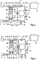
- Fig. 3 shows a second embodiment of the dialysis machine, which differs from that with reference to the Fig. 1 and 2 described embodiment only differs in that in the bypass line 13, a fifth obturator 23 is connected, which is also actuated by the central control unit 18.
- the corresponding parts are therefore provided with the same reference numerals.
- the obturator 23 in the bypass line 13 is basically open during operation of the dialysis device.
- the obturator 23 may also for Interruption of the circulation of the dialysis fluid in the fluid circuit II are closed.
- the obturator 23 is closed in the bypass line 13, so that the liquid flow is interrupted by the bypass line.
- the second obturator 20 is closed so that liquid can not get into the drain 32.
- the liquid is supplied to the balance chamber 6 via the first inflow line 8 while the pump 10 is running. With running pumps 14 and 15, the liquid can flow through the second drain line 11, the dialyzer 1 and the second inflow line 12.
- a vent valve 33 is provided at the top of the balance chamber 6, which in Fig. 3 is shown only in an approximate way.
- Fig. 4 shows an alternative embodiment of the dialysis machine of Fig. 3
- the embodiment of Fig. 4 differs from the embodiment of Fig. 3 only by the leadership of the second drain line 11 and the second inflow line 12 and the length of the bypass line 13.
- the corresponding parts are again provided with the same reference numerals.
- the second outflow and inflow line 11, 12 are brought directly to the connections of the obturator 23, so that the volume of the bypass 13 can be reduced to a minimum.
- the inventive device for supplying the dialyzer with dialysis fluid has the advantage that can be dispensed with a balancing unit with two balancing chambers. Even with a balancing unit which has only one balance chamber, a continuous flow of dialysis fluid through the dialyzer can be maintained during the balancing of fresh versus used dialysis fluid.
- Fig. 5 shows the sake of completeness, a dialysis device with two parallel-connected balancing chambers 6A, 6B, which are operated alternately.
- the embodiment of Fig. 5 differs from the embodiment of Fig. 1 and FIG. 2 in that the second balancing chamber 6B is connected in parallel with the associated inlet and outlet lines 24, 25, 26, 27, into which respective shut-off elements 28, 29, 30, 31 are connected.
- the balancing unit 6 with two balancing chambers 6A, 6B is operated in a known manner, such as in the DE 28 38 414 is described.
- Fig. 6 shows a further embodiment, which differs from the embodiment of Fig. 4 only differs in that the balance chamber 6 is divided by a flexible partition 6G in a first chamber half 6E and a second chamber half 6F.
- the first inlet 6A and the second outlet 6D communicate with the first chamber half 6E
- the second inlet 6C and the first outlet 6B communicate with the second chamber half 6F.
- Both chamber halves 6E and 6F of the balance chamber 6 are alternately filled in this embodiment with fresh and used dialysis fluid.
- the corresponding parts are again provided with the same reference numerals.
- the fluid circuit II allows the maintenance of the flow of dialysis fluid through the dialyzer 1 during filling of the balance chamber 6 with fresh dialysis fluid. If the respective chamber half 6E or 6F is filled with fresh dialysis fluid, the used dialysis fluid is displaced from the respective other chamber half 6F or 6E.
Description
Die Erfindung betrifft eine Vorrichtung zum Fördern von Flüssigkeiten in die Behandlungseinheit einer medizinischen Behandlungsvorrichtung, insbesondere in den Dialysator einer Dialysevorrichtung. Darüber hinaus betrifft die Erfindung eine extrakorporale Blutbehandlungsvorrichtung, insbesondere Dialysevorrichtung, die über eine Vorrichtung zum Fördern von Flüssigkeiten in die Behandlungseinheit, insbesondere den Dialysator, der Blutbehandlungsvorrichtung, insbesondere Dialysevorrichtung, verfügt.The invention relates to a device for conveying liquids into the treatment unit of a medical treatment device, in particular into the dialyzer of a dialysis machine. Moreover, the invention relates to an extracorporeal blood treatment apparatus, in particular a dialysis apparatus, which has a device for conveying liquids into the treatment unit, in particular the dialyzer, the blood treatment apparatus, in particular the dialysis apparatus.
Es sind verschiedene Arten von Behandlungsvorrichtungen bekannt, die über eine mit einer Flüssigkeit zu versorgende Behandlungseinheit verfügen. Zu den bekannten Behandlungsvorrichtungen gehören beispielsweise die Blutbehandlungsvorrichtungen. Während der Blutbehandlung strömt das Blut des Patienten in einem extrakorporalen Blutkreislauf durch die Blutbehandlungseinheit. Bei den Vorrichtungen zur Hämodialyse, Hämofiltration und Hämodiafiltration ist die Blutbehandlungseinheit ein Dialysator oder Filter, der durch eine semipermeable Membran in eine Blutkammer und eine Dialysierflüssigkeitskammer getrennt ist. Während der Dialysebehandlung strömt das Blut in einem extrakorporalen Blutkreislauf durch die Blutkammer, während die Dialysierflüssigkeit in einem Dialysierflüssigkeitskreislauf durch die Dialysierflüssigkeitskammer des Dialysators strömt.Various types of treatment devices are known which have a treatment unit to be supplied with a liquid. The known treatment devices include, for example, the blood treatment devices. During the blood treatment, the patient's blood flows through the blood treatment unit in an extracorporeal blood circulation. In the devices for hemodialysis, hemofiltration and hemodiafiltration, the blood treatment unit is a dialyzer or filter which is separated by a semipermeable membrane into a blood chamber and a dialysis fluid chamber. During the dialysis treatment, the blood flows in an extracorporeal blood circulation through the blood chamber while the dialysis fluid flows in a dialysis fluid circuit through the dialysis fluid chamber of the dialyzer.
Wegen der großen Austauschmengen besteht bei den bekannten Verfahren und Vorrichtungen zur Blutbehandlung die Notwendigkeit einer exakten Bilanzierung der dem Patienten entzogenen Flüssigkeit und der dem Patienten zugeführten Flüssigkeit über die gesamte Behandlungszeit. Zum Stand der Technik gehören gravimetrische und volumetrische Bilanziervorrichtungen.Because of the large amount of replacements, the prior art blood treatment methods and devices require the need to accurately account for the fluid withdrawn from the patient and the fluid being delivered to the patient throughout the treatment period. The prior art includes gravimetric and volumetric balancers.
Eine Hämodiafiltrationsvorrichtung mit volumetrischer Bilanzierung ist beispielsweise aus der
Um einen kontinuierlichen Fluss von Dialysierflüssigkeit durch die Dialysierflüssigkeitskammer des Dialysators sicherstellen zu können, werden in der Praxis zwei Bilanzkammern parallel geschaltet, die den Dialysator wechselseitig mit frischer Dialysierflüssigkeit versorgen. Eine Bilanziereinheit mit zwei Bilanzkammern ist beispielsweise aus der
Während einer Dialysebehandlung beträgt der Dialysierflüssigkeitsfluss typischerweise 500 ml/min, kann aber in Abhängigkeit von der jeweiligen Behandlungssituation bis zu 1000 ml/min betragen. Bei einer Dialysedauer von 4 Stunden bedeutet dies einen Dialysierflüssigkeitsbedarf, der typischerweise zwischen 120 1 beträgt, in Abhängigkeit von der jeweiligen Behandlungssituation aber auch über 200 1 liegen kann.During a dialysis treatment, the dialysis fluid flow is typically 500 ml / min, but may be up to 1000 ml / min, depending on the particular treatment situation. With a dialysis duration of 4 hours, this means a dialysis fluid need, which is typically between 120 1, depending on the particular treatment situation but can also be over 200 1.
Aufgrund des großen Flüssigkeitsbedarfs bei der Dialyse hat sich die Herstellung des Dialysats aus Konzentraten und Reinwasser (RO-Wasser) in der Maschine etabliert, um die Vorhaltung größerer Mengen an Lösungen zu vermeiden. Das RO-Wasser wird zentral in der Klinik bereitgestellt und an die Dialaysemaschine in den Dialysestationen über Leitungen verteilt.Due to the large fluid requirement in dialysis, the production of dialysate from concentrates and pure water (RO water) has established in the machine to avoid the provision of larger amounts of solutions. The RO water is provided centrally in the clinic and distributed to the dialysis machine in the dialysis stations via lines.
Bei der Behandlung einer akuten Niereninsuffizienz, wie sie beispielsweise nach Unfällen vorkommen kann, die eine intensivmedizinische Betreuung des Patienten notwendig macht, ist im allgemeinen ein RO-Wasseranschluss nicht vorhanden. Die Dialysierflüssigkeit wird der Maschine dann über Behältnisse, beispielsweise Kanister oder Beutel, zur Verfügung gestellt.In the treatment of acute renal insufficiency, as may occur, for example, after accidents requiring intensive medical care of the patient, there is generally no RO water connection. The Dialysis fluid is then provided to the machine via containers, such as canisters or bags.
Um den Handhabungsaufwand möglichst gering zu halten, wird insbesondere bei der intensivmedizinischen Betreuung einer akuten Niereninsuffizienz versucht, den Bedarf an Dialysierflüssigkeit zu verringern. Dies gelingt dadurch, dass die Dialysierflüssigkeit für eine gewisse Zeit über den Dialysator rezirkuliert wird. Damit kann der Dialysatbedarf auf Werte reduziert werden, die unter 100 ml/min liegen.In order to keep the handling effort as low as possible, an attempt is made to reduce the need for dialysis fluid, particularly in intensive care for acute renal insufficiency. This is achieved in that the dialysis fluid is recirculated over the dialyzer for a certain time. Thus, the dialysate requirement can be reduced to values that are below 100 ml / min.
Eine Blutbehandlungsvorrichtung mit einem Rezirkulationskreislauf ist beispielsweise aus der
Aus der
Aus der
Die
Die
Die
Aus der
Der Erfindung liegt die Aufgabe zugrunde, eine Vorrichtung zum Fördern von Flüssigkeiten in die Behandlungseinheit einer medizinischen Behandlungsvorrichtung, insbesondere in den Dialysator einer Dialysevorrichtung, zu schaffen, mit der sich der Bedarf an Dialysierflüssigkeit verringern lässt.The invention has for its object to provide a device for conveying liquids in the treatment unit of a medical treatment device, in particular in the dialyzer of a dialysis machine, with which it is possible to reduce the need for dialysis.
Die Lösung dieser Aufgabe erfolgt erfindungsgemäß mit den Merkmalen der unabhängigen Patentansprüche. Vorteilhafte Ausführungsformen der Erfindung sind Gegenstand der Unteransprüche.The solution of this object is achieved according to the invention with the features of the independent claims. Advantageous embodiments of the invention are the subject of the dependent claims.
Die erfindungsgemäße Vorrichtung beruht darauf, dass die Flüssigkeit, mit der die Behandlungseinheit versorgt wird, in einem die Behandlungseinheit einschließenden Flüssigkeitskreislauf zirkuliert. Zur Bilanzierung von frischer und verbrauchter Flüssigkeit, die der Behandlungseinheit zugeführt oder aus der Behandlungseinheit abgeführt wird, dient eine Bilanziereinheit, die grundsätzlich eine oder zwei Bilanzkammern aufweisen kann.The device according to the invention is based on the fact that the liquid with which the treatment unit is supplied circulates in a fluid circuit enclosing the treatment unit. For balancing fresh and used liquid supplied to or from the treatment center Treatment unit is discharged, serves a balancing unit, which may basically have one or two balancing chambers.
Die erfindungsgemäße Vorrichtung zeichnet sich dadurch aus, dass die Bilanzkammer der Bilanziereinheit, oder die beiden Bilanzkammern der Bilanziereinheit in den die Behandlungseinheit einschließenden Flüssigkeitskreislauf eingebunden werden kann. Dadurch ist es möglich, dem Flüssigkeitskreislauf kontinuierlich frische Flüssigkeit zuzuführen bzw. verbrauchte Flüssigkeit aus dem Flüssigkeitskreislauf abzuführen. Dabei kann die Zu- und Abfuhr von frischer bzw. verbrauchter Flüssigkeit mit einer anderen Flussrate erfolgen, als mit der Flussrate, mit der die Flüssigkeit in dem Flüssigkeitskreislauf über die Behandlungseinheit zirkuliert. Folglich stellt sich in dem Flüssigkeitskreislauf eine "Flüssigkeit" ein, die in Abhängigkeit von dem Verhältnis der Flussraten in der Konzentration zwischen einer "frischen Flüssigkeit" und einer "verbrauchten Flüssigkeit" liegt. Dem die Blutbehandlungseinheit, insbesondere den Dialysator, einschließenden Flüssigkeitskreislauf kann unabhängig von der Zufuhr bzw. Abfuhr von frischer bzw. verbrauchter Flüssigkeit auch Flüssigkeit (Ultrafiltrat) entzogen werden.The device according to the invention is characterized in that the balancing chamber of the balancing unit, or the two balancing chambers of the balancing unit, can be integrated into the fluid circuit enclosing the treatment unit. This makes it possible to continuously supply fresh liquid to the liquid circuit or to remove used liquid from the liquid circuit. In this case, the supply and removal of fresh or spent fluid can be carried out at a different flow rate, as with the flow rate at which the liquid circulates in the fluid circuit via the treatment unit. Consequently, a "liquid" sets in the liquid circuit which, depending on the ratio of the flow rates, lies in the concentration between a "fresh liquid" and a "spent liquid". The blood circulation unit, in particular the dialyzer, enclosing liquid circuit can be withdrawn regardless of the supply or discharge of fresh or spent liquid and liquid (ultrafiltrate).
Die Mittel zum Fördern von Flüssigkeit weisen zwei Pumpen auf, die in der von der Bilanzkammer zu der Blutbehandlungseinheit führenden Abflussleitung angeordnet sind. Von diesen beiden Pumpen ist die eine Pumpe in dem Abschnitt dieser Abflussleitung angeordnet, der zu dem Punkt führt, an dem der eine Anschluss des Bypasses an die Abflussleitung angeschlossen ist, während die andere Pumpe in dem Abschnitt dieser Abflussleitung angeordnet ist, der von dem Anschlusspunkt des Bypasses abgeht. Die Flussraten dieser beiden Pumpen in der Abflussleitung geben die Flussrate vor, mit der frische Flüssigkeit dem Flüssigkeitskreislauf zugeführt bzw. verbrauchte Flüssigkeit aus dem Flüssigkeitskreislauf abgeführt wird.The means for conveying liquid have two pumps, which are arranged in the discharge line leading from the balance chamber to the blood treatment unit. Of these two pumps, one pump is disposed in the portion of this drainage conduit leading to the point where one port of the bypass is connected to the drainage conduit while the other pump is located in the portion of this drainage conduit which is from the attachment point going off the bypass. The flow rates of these two pumps in the drain line provide the flow rate at which fresh liquid is fed to the liquid loop, or spent liquid is removed from the liquid loop.
Bei einer bevorzugten Ausführungsform der Erfindung ist die Flussrate, mit der die Flüssigkeit über die Behandlungseinheit in dem Flüssigkeitskreislauf zirkuliert, größer als die Flussrate, mit der Flüssigkeit dem Flüssigkeitskreislauf zu- bzw. abgeführt wird.In a preferred embodiment of the invention, the flow rate at which the liquid circulates through the treatment unit in the fluid circuit is greater than the flow rate at which fluid is supplied to or removed from the fluid circuit.
Die erfindungsgemäße Vorrichtung verfügt über einen Bypass, der die von der Bilanzkammer zu der Behandlungseinheit führende Abflussleitung mit der von der Behandlungseinheit zu der Bilanzkammer führenden Zuflussleitung verbindet. Der Bypass erlaubt nicht nur eine kontinuierliche Zufuhr frischer Flüssigkeit in den die Behandlungseinheit einschließenden Flüssigkeitskreislauf, sondern auch die Aufrechterhaltung eines Flüssigkeitsflusses durch die Blutbehandlungseinheit, wenn die Bilanzkammer der Bilanziereinheit mit frischer Flüssigkeit unter Verwerfung verbrauchter Flüssigkeit befüllt wird. Wenn eine Bilanziereinheit mit zwei wechselseitig arbeitenden Bilanzkammern verwendet wird, kommt dieser Vorteil allerdings nicht zum Tragen. Eine besonders bevorzugte Ausführungsform der Erfindung sieht daher eine Bilanziereinheit mit nur einer Bilanzkammer vor. Bei dieser besonders bevorzugten Ausführungsform stellt der Bypass sicher, dass beim Umschalten der Bilanzkammer die Flüssigkeitsströmung durch die Blutbehandlungseinheit nicht abbricht. Dadurch ergibt sich ein vereinfachter Aufbau der Bilanziereinheit.The device according to the invention has a bypass which leads the discharge line leading from the balancing chamber to the treatment unit with that of the Treatment unit to the balance chamber leading inflow line connects. The bypass allows not only a continuous supply of fresh fluid into the fluid circuit enclosing the treatment unit, but also the maintenance of a fluid flow through the blood treatment unit when the balance chamber of the balancing unit is filled with fresh fluid with rejection of spent fluid. If a balancing unit with two reciprocating balancing chambers is used, however, this advantage does not come into play. A particularly preferred embodiment of the invention therefore provides a balancing unit with only one balancing chamber. In this particularly preferred embodiment, the bypass ensures that the liquid flow through the blood treatment unit does not break off when the balance chamber is switched over. This results in a simplified construction of the balancing unit.
Die Mittel zum Fördern von Flüssigkeit in die bzw. aus der Bilanzkammer und die Mittel zum Unterbrechen des Zuflusses von Flüssigkeit in die Bilanzkammer bzw. des Abflusses von Flüssigkeit aus der Bilanzkammer können unterschiedlich ausgebildet sein. Zum Fördern von Flüssigkeit dienen vorzugsweise die bekannten okkludierenden Pumpen, in die sich Schlauchleitungen einlegen lassen. Zum Unterbrechen des Zuflusses bzw. Abflusses von Flüssigkeit dienen vorzugsweise die bekannten elektromagnetisch oder pneumatisch betätigbaren Absperrorgane, die in den Leitungen angeordnet sind. Eine Steuereinheit steuert die Mittel zum Fördern von Flüssigkeit und die Mittel zum Unterbrechen des Zuflusses bzw. Abflusses von Flüssigkeit an. Da okkludierende Pumpen im Stillstand die Schlauchleitung abklemmen, können die okkludierenden Pumpen auch Absperrorgane ersetzen.The means for conveying liquid into and out of the balance chamber and the means for interrupting the inflow of liquid into the balance chamber or the outflow of liquid from the balance chamber may be formed differently. To convey liquid, it is preferable to use the known occluding pumps in which hose lines can be inserted. To interrupt the inflow or outflow of liquid preferably serve the known electromagnetically or pneumatically actuated shut-off devices which are arranged in the lines. A control unit controls the means for conveying liquid and the means for interrupting the inflow or outflow of liquid. Since occluding pumps at standstill disconnect the tubing, the occluding pumps can also replace shut-off valves.
Bei einer besonders bevorzugten Ausführungsform weisen die Mittel zum Fördern von Flüssigkeit eine weitere Pumpe auf, die in der von der Flüssigkeitsquelle zu der Bilanzkammer führenden Zuflussleitung angeordnet ist.In a particularly preferred embodiment, the means for conveying liquid to a further pump, which is arranged in the leading from the liquid source to the balance chamber inlet pipe.
Bei der besonders bevorzugten Ausführungsform umfassen die Mittel zum Unterbrechen des Zuflusses und/oder Abflusses von Flüssigkeit ein erstes Absperrorgan, das in der von der Flüssigkeitsquelle zu der Bilanzkammer führenden ersten Zuflussleitung angeordnet ist, ein zweites Absperrorgan, das in der von der Bilanzkammer abgehenden und zu dem Abfluss führenden zweiten Abflussleitung angeordnet ist, ein drittes Absperrorgan, das in der von der Bilanzkammer abgehenden und zu der Blutbehandlungseinheit führenden zweiten Abflussleitung angeordnet ist, und ein viertes Absperrorgan, das in der von der Behandlungseinheit zu der Bilanzkammer führenden zweiten Zuflussleitung angeordnet ist. Sämtliche Absperrorgane werden von der Steuereinheit angesteuert.In the particularly preferred embodiment, the means for interrupting the inflow and / or outflow of liquid comprise a first obturator which is in the of a second obturator, which is arranged in the outgoing from the balance chamber and leading to the outflow second drain line, a third obturator, in the outgoing from the balance chamber and leading to the blood treatment unit second drain line is arranged, and a fourth obturator, which is arranged in the leading from the treatment unit to the balancing chamber second inflow line. All shut-off devices are controlled by the control unit.
Die Steuereinheit ist bei der besonders bevorzugten Ausführungsform derart ausgebildet, dass in einem ersten Arbeitstakt eines ersten Arbeitszyklus von aufeinander folgenden Arbeitszyklen das erste und zweite Absperrorgan geöffnet und das dritte und vierte Absperrorgan geschlossen sind, wobei die erste und dritte Pumpe in Betrieb sind. In dem ersten Arbeitstakt wird die Bilanzkammer mit frischer Flüssigkeit unter Verwerfung verbrauchter Flüssigkeit befüllt. Während des Füllvorgangs der Bilanzkammer ist die Flüssigkeitsströmung durch die Behandlungseinheit nicht unterbrochen. An den ersten Arbeitstakt schließt sich ein zweiter Arbeitstakt an, in dem das erste und zweite Absperrorgan geschlossen und das dritte und vierte Absperrorgan geöffnet sind, wobei die zweite und dritte Pumpe in Betrieb sind. In dem zweiten Arbeitstakt zirkuliert die Flüssigkeit in dem die Behandlungseinheit einschließenden Flüssigkeitskreislauf. Dabei kann, muss aber nicht, frische Flüssigkeit dem Flüssigkeitskreislauf zugeführt bzw. aus dem Flüssigkeitskreislauf abgeführt werden.The control unit is formed in the particularly preferred embodiment such that in a first cycle of a first cycle of successive working cycles, the first and second shut-off and the third and fourth shut-off are closed, the first and third pump are in operation. In the first cycle, the balance chamber is filled with fresh liquid, with rejection of spent liquid. During the filling process of the balance chamber, the liquid flow through the treatment unit is not interrupted. The first power stroke is followed by a second power stroke in which the first and second shut-off elements are closed and the third and fourth shut-off devices are opened, with the second and third pumps in operation. In the second working cycle, the liquid circulates in the fluid circuit enclosing the treatment unit. It may, but does not necessarily, fresh liquid supplied to the liquid circuit or be discharged from the liquid circuit.
Eine weitere bevorzugte Ausführungsform sieht die Integration eines weiteren Absperrorgans im Bypass vor. Dieses Absperrorgan dient der besseren Befüllung und Entlüftung des Systems vor der Durchführung der Behandlung. Andererseits kann mit dem Absperrorgan im Bypass auch die Zirkulation in dem Flüssigkeitskreislauf unterbrochen werden.Another preferred embodiment provides for the integration of a further obturator in the bypass. This obturator is used to better fill and vent the system before performing the treatment. On the other hand, with the obturator in the bypass and the circulation in the fluid circuit can be interrupted.
Im Folgenden werden Ausführungsbeispiele der Erfindung unter Bezugnahme auf die Zeichnungen näher erläutert.In the following, embodiments of the invention will be explained in more detail with reference to the drawings.
Es zeigen:
- Fig. 1
- Eine Hämodialysevorrichtung mit einer Vorrichtung zur Versorgung des Dialysators der Dialysevorrichtung mit Dialysierflüssigkeit in stark vereinfachter schematischer Darstellung, wobei der erste Arbeitstakt eines Arbeitszyklus dargestellt ist,
- Fig. 2
- die Hämodialysevorrichtung von
Fig. 2 , wobei der zweite Arbeitstakt des Arbeitszyklus dargestellt ist, - Fig. 3
- ein zweites Ausführungsbeispiel der Hämodialysevorrichtung mit der Vorrichtung zur Versorgung des Dialysators mit Dialysierflüssigkeit in stark vereinfachter schematischer Darstellung,
- Fig. 4
- eine alternative Ausführungsform der Hämodialysevorrichtung von
Fig. 3 , - Fig. 5
- ein weiteres Ausführungsbeispiel der Dialysevorrichtung in stark vereinfachter schematischer Darstellung und
- Fig. 6
- eine alternative Ausführungsform der Dialysevorrichtung von
Fig. 5 .
- Fig. 1
- A hemodialysis apparatus with a device for supplying the dialyzer of the dialysis apparatus with dialysis fluid in a highly simplified schematic representation, wherein the first working cycle of a working cycle is shown,
- Fig. 2
- the hemodialysis device of
Fig. 2 showing the second working cycle of the work cycle, - Fig. 3
- A second embodiment of the hemodialysis apparatus with the device for supplying the dialyzer with dialysis fluid in a highly simplified schematic representation,
- Fig. 4
- an alternative embodiment of the hemodialysis of
Fig. 3 . - Fig. 5
- a further embodiment of the dialysis apparatus in a highly simplified schematic representation and
- Fig. 6
- an alternative embodiment of the dialysis device of
Fig. 5 ,
Die Erfindung wird nachfolgend am Beispiel einer Blutbehandlungsvorrichtung beschrieben, die über einen Dialysator als Blutbehandlungseinheit verfügt.
Die Dialysevorrichtung weist einen Dialysator 1 auf, der durch eine nicht dargestellte semipermeable Membran in eine nicht dargestellte Blutkammer und Dialysierflüssigkeitskammer unterteilt ist. Von dem Patienten führt eine Blutzuführleitung 2, in die eine Blutpumpe 3 geschaltet ist, zu einem Einlass 1A der Blutkammer des Dialysators 1, während von einem Auslass 1B der Blutkammer des Dialysators 1 eine Blutabführleitung 4 abgeht, die zu dem Patienten führt. Während der Blutbehandlung strömt das Blut des Patienten in dem extrakorporalen Blutkreislauf I durch die Blutkammer des Dialysators 1.The dialysis apparatus has a dialyzer 1, which is subdivided by a semipermeable membrane, not shown, into a blood chamber and dialysis fluid chamber, not shown. From the patient leads a blood supply line 2, in which a
Der Dialysator 1 wird mit Dialysierflüssigkeit versorgt, die durch die Dialysierflüssigkeitskammer des Dialysators 1 strömt. Nachfolgend wird die Vorrichtung zum Fördern der Dialysierflüssigkeit in den Dialysator 1 beschrieben.The dialyzer 1 is supplied with dialysis fluid which flows through the dialysis fluid chamber of the dialyzer 1. The device for conveying the dialysis fluid into the dialyzer 1 will be described below.
Zum Bilanzieren von frischer gegen verbrauchte Dialysierflüssigkeit dient eine Bilanziereinheit 5, die bei dem vorliegenden Ausführungsbeispiel nur über eine Bilanzkammer 6 verfügt. Die Bilanzkammer 6 weist an der Unterseite einen ersten Einlass 6A und an der Oberseite einen ersten Auslass 6B sowie an der Unterseite einen zweiten Einlass 6C und an der Oberseite einen zweiten Auslass 6D auf.For balancing fresh against spent dialysis fluid is a
Die Dialysierflüssigkeit wird in einer Dialysierflüssigkeitsquelle 7 bereitgestellt, bei der es sich um einen Kanister oder einen Beutel handeln kann. Von der Dialysierflüssigkeitsquelle 7 geht eine erste Zuflussleitung 8 ab, die zu dem ersten Einlass 6A der Bilanzkammer 6 führt. Von dem ersten Auslass 6B der Bilanzkammer 6 geht eine erste Abflussleitung 9 ab, die zu einem Ablauf oder Abfluss 32 führt. In die erste Zuflussleitung 8 ist eine Blutpumpe 10, insbesondere eine okkludierende Pumpe, geschaltet, die frische Dialysierflüssigkeit aus der Dialysierflüssigkeitsquelle 7 in die Bilanzkammer 6 fördert.The dialysis fluid is provided in a
Von dem zweiten Auslass 6D der Bilanzkammer 6 geht eine zweite Abflussleitung 11 ab, die zu dem Einlass 1C der Dialysierflüssigkeitskammer des Dialysators 1 führt. Von dem Auslass 1 D der Dialysierflüssigkeitskammer des Dialysators 1 geht eine zweite Zuflussleitung 12 ab, die zu dem zweiten Einlass 6C der Bilanzkammer 6 führt.From the
Bei den Zu- und Abflussleitungen 8, 9, 11, 12 handelt es sich um Schlauchleitungen. Die zweite Abflussleitung 11 weist in Strömungsrichtung einen ersten Abschnitt 11A und einen zweiten Abschnitt 11 B auf, während die zweite Zuflussleitung 12 in Strömungsrichtung einen ersten Abschnitt 12A und einen zweiten Abschnitt 12B aufweist.The inflow and
Die zweite Abflussleitung 11 und die zweite Zuflussleitung 12 sind über einen Bypass 13 verbunden. Bei dem Bypass 13 handelt es sich um eine Leitung, die mit dem einen Ende an dem Verbindungspunkt 11C zwischen dem ersten Abschnitt 11A und dem zweiten Abschnitt 11 B der zweiten Abflussleitung 11 und mit dem anderen Ende an dem Verbindungspunkt 12C zwischen dem ersten Abschnitt 12A und dem zweiten Abschnitt 12B der zweiten Zuflussleitung 12 angeschlossen ist. Mit dem Bypass 13 wird ein Flüssigkeitskreislauf II geschaffen, der die Dialysierflüssigkeitskammer des Dialysators 1 einschließt. Der Flüssigkeitskreislauf II umfasst die Bypass-Leitung 13, den zweiten Abschnitt 11B der zweiten Abflussleitung 11, die Dialysierflüssigkeitskammer des Dialysators 1 und den ersten Abschnitt 12A der zweiten Zuflussleitung 12.The
In den ersten Abschnitt 11 A der zweiten Abflussleitung 11 ist eine zweite Pumpe 14 und in den zweiten Abschnitt 11B der zweiten Abflussleitung 11 eine dritte Pumpe 15 geschaltet. Von dem ersten Abschnitt 12A der zweiten Zuflussleitung 12 geht eine Ultrafiltratleitung 16 ab, in die eine vierte Pumpe 17 geschaltet ist, mit der dem Flüssigkeitskreislauf II Flüssigkeit (Ultrafiltrat) entzogen werden kann. Die vier Pumpen 10, 14, 15, 17 sind über Steuerleitungen 10', 14', 15', 17' mit einer Steuereinheit 18 verbunden. Die Steuereinheit 18 ist bei dem vorliegenden Beispiel Bestandteil der zentralen Steuereinheit der Dialysevorrichtung. Die zentrale Steuereinheit 18 der Dialysevorrichtung ist über eine Steuerleitung 3' auch mit der Blutpumpe 3 verbunden.In the
In die erste Zuflussleitung 8 ist zwischen der ersten Pumpe 10 und der Bilanzkammer 6 ein erstes Absperrorgan 19 geschaltet, während in die erste Abflussleitung 9 ein zweites Absperrorgan 20 geschaltet ist. In die zweite Abflussleitung 11 ist zwischen der Bilanzkammer 6 und der zweiten Pumpe 14 ein drittes Absperrorgan 21 geschaltet, während in die zweite Zuflussleitung 12 zwischen dem Verbindungspunkt 12C und der Bilanzierkammer 6 ein drittes Absperrorgan 22 geschaltet ist. Die Absperrorgane 19, 20, 21, 22 sind elektromagnetisch betätigbare Schlauchklemmen, die über Steuerleitungen 19', 20', 21', 22' mit der zentralen Steuereinheit 18 verbunden sind.In the
Die zentrale Steuereinheit 18 steuert die Pumpen 10, 14, 15 wie folgt an. Die Dialysevorrichtung wird in aufeinanderfolgenden Zyklen betrieben, die jeweils zwei Arbeitstakte umfassen.
Der erste Arbeitstakt umfasst das Befüllen der Bilanzierkammer 6, während Dialysierflüssigkeit durch den Dialysator 1 strömt. Die zentrale Steuereinheit 18 öffnet das erste und zweite Absperrorgan 19, 20 und schließt das dritte und vierte Absperrorgan 21, 22. Dabei setzt die Steuereinheit 18 die erste Pumpe 10 und die dritte Pumpe 15 in Betrieb. Die zweite Pumpe 14 steht still. Da die zweite okkludierende Pumpe 14 stillsteht, kann das dritte Absperrorgan 21 auch offen sein.The first power stroke comprises the filling of the balancing
Die erste Pumpe 10 fördert frische Dialysierflüssigkeit aus der Dialysierflüssigkeitsquelle 7 in die Bilanzierkammer 6, die in dem zweiten Arbeitstakt des vorausgehenden Arbeitszyklus mit verbrauchter Dialysierflüssigkeit befüllt worden ist. Während sich die Bilanzkammer 6 mit frischer Dialysierflüssigkeit füllt, wird die verbrauchte Dialysierflüssigkeit über die erste Abflussleitung 9 in den Abfluss 32 verworfen. Die erste Pumpe 10 läuft solange, bis in der Bilanzkammer 6 verbrauchte Dialysierflüssigkeit vollständig gegen frische Dialysieflüssigkeit ausgetauscht ist. Während des Befüllens der Bilanzkammer 6 mit frischer Dialysierflüssigkeit ist die Flüssigkeitsströmung durch den Dialysator 1 nicht unterbrochen. Die dritte Pumpe 15 fördert die Dialysierflüssigkeit in dem Flüssigkeitskreislauf II, der den zweiten Abschnitt 11 B der zweiten Abflussleitung 11, den Dialysator 1, den ersten Abschnitt 12A der zweiten Zuflussleitung 12 und die Bypass-Leitung 13 einschließt. Die Bilanzkammer 6 sollte möglichst schnell mit frischer Dialysierflüssigkeit befüllt werden, so dass die Dialysierflüssigkeit nur eine kurze Zeitdauer in dem Flüssigkeitskreislauf zirkuliert (
An den ersten Arbeitstakt (
Während Dialysierflüssigkeit in dem Flüssigkeitskreislauf II durch den Dialysator 1 zirkuliert, wird dem Flüssigkeitskreislauf II ständig frische Dialysierflüssigkeit zugeführt und verbrauchte Dialysierflüssigkeit dem Flüssigkeitskreislauf 12 entzogen. Die frische Dialysierflüssigkeit wird mit der von der zweiten Pumpe 14 vorgegebenen Förderrate über den ersten Abschnitt 11A der zweiten Abflussleitung 11, die an den zweiten Auslass 6D der Bilanzierkammer 6 angeschlossen ist, dem Flüssigkeitskreislauf II zugeführt. Über den zweiten Abschnitt 12B der zweiten Zuflussleitung 12, die an dem zweiten Einlass 6C der Bilanzkammer 6 angeschlossen ist, wird verbrauchte Dialysierflüssigkeit dem Flüssigkeitskreislauf II entzogen. Die Dialysevorrichtung erlaubt auch dem Flüssigkeitskreislauf II Flüssigkeit (Ultrafiltrat) zu entziehen. Zur Ultrafiltration startet die Steuereinheit 18 die Ultrafiltrationspumpe 17.While dialysis fluid circulates in the fluid circuit II through the dialyzer 1, the liquid circuit II is constantly fed fresh dialysis fluid and withdrawn used dialysis liquid the
In Abhängigkeit von den Förderraten der zweiten und dritten Pumpe 14, 15 kann frische Dialysierflüssigkeit kontinuierlich in einem relativ kurzen oder einem relativ langen Zeitraum zugeführt und das gewünschte Verhältnis zwischen frischer und verbrauchter Dialysierflüssigkeit in dem Flüssigkeitskreislauf II eingestellt werden.Depending on the delivery rates of the second and
An den zweiten Arbeitstakt (
Zum Befüllen und Entlüften des Flüssigkeitssystems wird das Absperrorgan 23 in der Bypass-Leitung 13 geschlossen, so dass die Flüssigkeitsströmung durch die Bypass-Leitung unterbrochen ist. Weiterhin wird das zweite Absperrorgan 20 geschlossen, so dass Flüssigkeit nicht in den Ablauf 32 gelangen kann. Die Flüssigkeit wird über die erste Zuflussleitung 8 bei laufender Pumpe 10 der Bilanzkammer 6 zugeführt. Bei laufenden Pumpen 14 und 15 kann die Flüssigkeit durch die zweite Ablaufleitung 11, den Dialysator 1 und die zweite Zuflussleitung 12 strömen. Zur Entlüftung ist ein Entlüftungsventil 33 an der Oberseite der Bilanzkammer 6 vorgesehen, das in
For filling and venting of the liquid system, the
Die erfindungsgemäße Vorrichtung zum Versorgen des Dialysators mit Dialysierflüssigkeit hat den Vorteil, dass auf eine Bilanziereinheit mit zwei Bilanzkammern verzichtet werden kann. Auch mit einer Bilanziereinheit, die nur über eine Bilanzkammer verfügt, kann eine kontinuierliche Strömung von Dialysierflüssigkeit durch den Dialysator während der Bilanzierung von frischer gegen verbrauchte Dialysierflüssigkeit aufrecht erhalten werden.The inventive device for supplying the dialyzer with dialysis fluid has the advantage that can be dispensed with a balancing unit with two balancing chambers. Even with a balancing unit which has only one balance chamber, a continuous flow of dialysis fluid through the dialyzer can be maintained during the balancing of fresh versus used dialysis fluid.
Claims (11)
- A device for conveying fluid into the treatment unit of a medical treatment apparatus with
a balancing unit (5) which comprises at least one balancing chamber (6),
a first supply line (8) leading to the balancing chamber for supplying fluid from a fluid source (7) into the balancing chamber and a first discharge line (9) leading away from the balancing chamber for discharging fluid from the balancing chamber into a drain (32),
a second discharge line (11) leading away from the balancing chamber for discharging fluid from the balancing chamber into a treatment unit (1) and a second supply line (12) leading to the balancing chamber for supplying fluid from the treatment unit into the balancing chamber,
means (10, 14, 15) for conveying fluid into and/or out of the balancing chamber and means (19, 20, 21, 22) for interrupting the supply of fluid into the balancing chamber and/or discharge of fluid from the balancing chamber,
a control unit (18) for controlling the means (10, 14, 15) for conveying fluid and means (19, 20, 21, 22) for interrupting the supply and/or discharge of fluid,
a bypass (13) connecting the second discharge line (11) to the second supply line (12), which is designed such that a fluid circuit (II) including the treatment unit (1) is created thereby completely or partially bypassing the balancing chamber (6),
wherein the second discharge line (11) comprises a first and a second section (11A, 11B) in the flow direction and the second supply line (12) comprises a first and a second section (12A, 12B) in the flow direction, and one connection of the bypass (13) is connected to the junction point (11C) between the first and the second section of the second discharge line and the other connection of the bypass is connected to the junction point (12C) between the first and the second section of the second supply line, and
characterised in that the means for conveying fluid comprise a first pump (14), which is disposed in the first section (11A) of the second discharge line (11), and a second pump (15), which is disposed in the second section (11B) of the second discharge line (11). - The device according to claim 1, characterised in that the means (10, 14, 15) for conveying fluid and means (19, 20, 21, 22) for interrupting the supply and/or discharge of fluid are designed such that a fluid flow in the fluid circuit (II) including the treatment unit (1) can be adjusted at a predetermined flow rate.
- The device according to claim 2, characterised in that the control unit (18) is designed such that,
in a first work step of a first work cycle of successive work cycles, the balancing chamber (6) is filled via the first supply line (8) with fluid from the fluid source (7), fluid thereby being displaced out of the balancing chamber via the first discharge line (9) into the drain (32), whereby fluid circulates in the fluid circuit (II) including the treatment unit completely bypassing the balancing chamber, and,
in a second work step of the successive work cycles, fluid is carried away from the balancing chamber (6) via the second discharge line (11) and fluid is fed to the balancing chamber via the second supply line (12), whereby fluid circulates in the fluid circuit (II) including the treatment unit. - The device according to any one of claims 1 to 3, characterised in that the means for conveying fluid comprise a third pump (10), which is disposed in the first supply line (8).
- The device according to any one of claims 1 to 4, characterised in that the means for interrupting the supply and/or discharge of fluid comprise:a first shut-off element (19) disposed in the first supply line (8),a second shut-off element (20) disposed in the first discharge line (9),a third shut-off element (21) disposed in the second discharge line (11),a fourth shut-off element (22) disposed in the second supply line (12).
- The device according to any one of claims 1 to 5, characterised in that the means for conveying fluid and means for interrupting the supply and/or discharge of fluid comprise a fifth shut-off element (23) which is disposed in the bypass (13).
- The device according to claims 5 and 6, characterised in that the control unit (18) is designed such that the first and second shut-off elements (19, 20) are opened and the third and fourth shut-off elements (21, 22) are closed in a first work step of a first work cycle of successive work cycles, the second and third pumps (15, 10) being in operation, and
the first and second shut-off elements (19, 20) are closed and the third and fourth shut-off elements (21, 22) are opened in a second work step of successive work cycles, the first and second pumps (14, 15) being in operation. - The device according to claim 7, characterised in that the control unit (18) is designed such that the first and second pumps (14, 15) are operated in different delivery modes in the second work step.
- The device according to claim 7 or 8, characterised in that the control unit (18) is designed such that the second pump (15) is operated in the second work step at a delivery rate which is greater than the delivery rate of the first pump (14).
- An apparatus for extracorporeal blood treatment with a device according to any one of claims 1 to 9.
- The extracorporeal blood treatment apparatus according to claim 10, characterised in that the blood treatment apparatus is a dialysis apparatus, the blood treatment unit being a dialyser (1).
Applications Claiming Priority (2)
| Application Number | Priority Date | Filing Date | Title |
|---|---|---|---|
| DE201010023635 DE102010023635A1 (en) | 2010-06-14 | 2010-06-14 | Device and method for conveying liquids into the treatment unit of a medical treatment device, in particular into the dialyzer of a dialysis machine |
| PCT/EP2011/002915 WO2011157396A1 (en) | 2010-06-14 | 2011-06-14 | Method and device for delivering liquids into the treatment unit of a medical treatment device, in particular into the dialyser of a dialysis device |
Publications (2)
| Publication Number | Publication Date |
|---|---|
| EP2579912A1 EP2579912A1 (en) | 2013-04-17 |
| EP2579912B1 true EP2579912B1 (en) | 2017-01-04 |
Family
ID=44628496
Family Applications (1)
| Application Number | Title | Priority Date | Filing Date |
|---|---|---|---|
| EP11732366.7A Active EP2579912B1 (en) | 2010-06-14 | 2011-06-14 | Method and device for delivering liquids into the treatment unit of a medical treatment device, in particular into the dialyser of a dialysis device |
Country Status (7)
| Country | Link |
|---|---|
| US (1) | US9603987B2 (en) |
| EP (1) | EP2579912B1 (en) |
| JP (1) | JP5778265B2 (en) |
| CN (1) | CN102985121B (en) |
| BR (1) | BR112012032035B1 (en) |
| DE (1) | DE102010023635A1 (en) |
| WO (1) | WO2011157396A1 (en) |
Families Citing this family (25)
| Publication number | Priority date | Publication date | Assignee | Title |
|---|---|---|---|---|
| US10089443B2 (en) | 2012-05-15 | 2018-10-02 | Baxter International Inc. | Home medical device systems and methods for therapy prescription and tracking, servicing and inventory |
| CN105288763B (en) | 2011-08-02 | 2018-01-02 | 美敦力公司 | Hemodialysis system with the flow path with controllable compliance volume |
| ES2534477T5 (en) * | 2012-05-09 | 2018-07-20 | D_Med Consulting Ag | Procedure for priming a hemodialysis device |
| US9713666B2 (en) | 2013-01-09 | 2017-07-25 | Medtronic, Inc. | Recirculating dialysate fluid circuit for blood measurement |
| US10850016B2 (en) | 2013-02-01 | 2020-12-01 | Medtronic, Inc. | Modular fluid therapy system having jumpered flow paths and systems and methods for cleaning and disinfection |
| US10010663B2 (en) | 2013-02-01 | 2018-07-03 | Medtronic, Inc. | Fluid circuit for delivery of renal replacement therapies |
| US9623164B2 (en) | 2013-02-01 | 2017-04-18 | Medtronic, Inc. | Systems and methods for multifunctional volumetric fluid control |
| DE102013019356A1 (en) | 2013-11-19 | 2015-06-03 | Fresenius Medical Care Deutschland Gmbh | Apparatus and method for balancing fluids for an extracorporeal blood treatment device |
| US9884145B2 (en) | 2013-11-26 | 2018-02-06 | Medtronic, Inc. | Parallel modules for in-line recharging of sorbents using alternate duty cycles |
| US10537875B2 (en) | 2013-11-26 | 2020-01-21 | Medtronic, Inc. | Precision recharging of sorbent materials using patient and session data |
| DE102013021012A1 (en) * | 2013-12-13 | 2015-06-18 | Fresenius Medical Care Deutschland Gmbh | Device for extracorporeal blood treatment |
| DE102014003619A1 (en) * | 2014-03-13 | 2015-09-17 | Fresenius Medical Care Deutschland Gmbh | Apparatus and method for balancing an inflow and outflow from a medical treatment device |
| US10357757B2 (en) | 2014-06-24 | 2019-07-23 | Medtronic, Inc. | Stacked sorbent assembly |
| WO2015199766A1 (en) | 2014-06-24 | 2015-12-30 | Medtronic, Inc. | Modular dialysate regeneration assembly |
| WO2017084682A1 (en) | 2015-11-20 | 2017-05-26 | Hepa Wash Gmbh | Method for extracorporeal carbon dioxide removal |
| WO2017084683A1 (en) | 2015-11-20 | 2017-05-26 | Hepa Wash Gmbh | Method for extracorporeal lung support |
| CN105727382B (en) * | 2016-01-28 | 2017-12-22 | 龚德华 | A kind of continous way CRRT machine capability bascules of two tripper |
| RU2729725C2 (en) * | 2016-03-14 | 2020-08-11 | Хепа Уош Гмбх | Systems or devices and methods of dialysis |
| DE102016010222A1 (en) * | 2016-08-20 | 2018-02-22 | Fresenius Medical Care Deutschland Gmbh | Device and method for providing dialysis fluid and dialysis device |
| US10981148B2 (en) | 2016-11-29 | 2021-04-20 | Medtronic, Inc. | Zirconium oxide module conditioning |
| US11344656B2 (en) | 2017-05-22 | 2022-05-31 | Advitos Gmbh | Methods and systems for removing carbon dioxide |
| US10960381B2 (en) | 2017-06-15 | 2021-03-30 | Medtronic, Inc. | Zirconium phosphate disinfection recharging and conditioning |
| DE102017131192A1 (en) * | 2017-12-22 | 2019-06-27 | Fresenius Medical Care Deutschland Gmbh | Buffer solution for reducing the carbon dioxide content in extracorporeal blood |
| US11213616B2 (en) | 2018-08-24 | 2022-01-04 | Medtronic, Inc. | Recharge solution for zirconium phosphate |
| DE102019130294A1 (en) * | 2019-11-11 | 2021-05-12 | Fresenius Medical Care Deutschland Gmbh | Dialysis machine for carrying out a push-pull dialysis treatment |
Citations (1)
| Publication number | Priority date | Publication date | Assignee | Title |
|---|---|---|---|---|
| DE69400279T2 (en) * | 1993-10-15 | 1996-11-21 | Hospal Ag | DIALYSIS LIQUID CIRCUIT |
Family Cites Families (13)
| Publication number | Priority date | Publication date | Assignee | Title |
|---|---|---|---|---|
| DE2634238A1 (en) | 1976-07-30 | 1978-02-02 | Berghof Forschungsinst | Dialysis liquor substitution in blood dialysis - uses cells with flexible membranes to allow balanced replacement |
| DE2838414C2 (en) | 1978-09-02 | 1984-10-31 | Fresenius AG, 6380 Bad Homburg | Device for hemodialysis and for withdrawing ultrafiltrate |
| US4209391A (en) * | 1978-11-06 | 1980-06-24 | Cordis Dow Corp. | Apparatus and method for automatically controlling hemodialysis at a pre-selected ultrafiltration rate |
| FR2680975B1 (en) * | 1991-09-10 | 1998-12-31 | Hospal Ind | ARTIFICIAL KIDNEY WITH MEANS FOR DETERMINING A SUBSTANCE IN BLOOD. |
| DE4239937C2 (en) * | 1992-11-27 | 1995-08-24 | Fresenius Ag | Method for determining the functionality of a partial device of a hemodialysis machine and device for carrying out this method |
| US5685988A (en) | 1993-09-15 | 1997-11-11 | Malchesky; Paul | Dialysis process and system |
| JP3892921B2 (en) * | 1996-11-19 | 2007-03-14 | 東レ・メディカル株式会社 | Hemodialysis machine |
| DE19702211A1 (en) * | 1997-01-23 | 1998-07-30 | Polaschegg Hans Dietrich Dr | Haemodialysis appts |
| DE19708391C1 (en) * | 1997-03-01 | 1998-10-22 | Fresenius Medical Care De Gmbh | Method and device for ultrafiltration in hemodialysis |
| JP4093695B2 (en) * | 1999-02-19 | 2008-06-04 | フレセニウス・メディカル・ケア・ドイッチュラント・ゲゼルシャフト・ミット・ベシュレンクテル・ハフツング | Dialysis treatment device |
| DE29902953U1 (en) * | 1999-02-19 | 2000-07-13 | Fresenius Medical Care De Gmbh | Device for dialysis treatment |
| DE602007008544D1 (en) * | 2007-06-20 | 2010-09-30 | Braun B Avitum Ag | Device for determining the reduction ratio or the Kt / V ratio of renal replacement therapy |
| US9101716B2 (en) | 2008-02-01 | 2015-08-11 | Baxter International Inc. | Multi-pass dialysis |
-
2010
- 2010-06-14 DE DE201010023635 patent/DE102010023635A1/en not_active Ceased
-
2011
- 2011-06-14 US US13/703,691 patent/US9603987B2/en active Active
- 2011-06-14 JP JP2013514581A patent/JP5778265B2/en active Active
- 2011-06-14 CN CN201180029575.0A patent/CN102985121B/en active Active
- 2011-06-14 BR BR112012032035-1A patent/BR112012032035B1/en active IP Right Grant
- 2011-06-14 EP EP11732366.7A patent/EP2579912B1/en active Active
- 2011-06-14 WO PCT/EP2011/002915 patent/WO2011157396A1/en active Application Filing
Patent Citations (1)
| Publication number | Priority date | Publication date | Assignee | Title |
|---|---|---|---|---|
| DE69400279T2 (en) * | 1993-10-15 | 1996-11-21 | Hospal Ag | DIALYSIS LIQUID CIRCUIT |
Also Published As
| Publication number | Publication date |
|---|---|
| BR112012032035A2 (en) | 2016-11-08 |
| CN102985121A (en) | 2013-03-20 |
| BR112012032035B1 (en) | 2020-10-06 |
| JP5778265B2 (en) | 2015-09-16 |
| CN102985121B (en) | 2016-08-17 |
| US20130087210A1 (en) | 2013-04-11 |
| DE102010023635A1 (en) | 2011-12-15 |
| EP2579912A1 (en) | 2013-04-17 |
| JP2013532018A (en) | 2013-08-15 |
| US9603987B2 (en) | 2017-03-28 |
| WO2011157396A1 (en) | 2011-12-22 |
Similar Documents
| Publication | Publication Date | Title |
|---|---|---|
| EP2579912B1 (en) | Method and device for delivering liquids into the treatment unit of a medical treatment device, in particular into the dialyser of a dialysis device | |
| EP1996253B1 (en) | Method for at least partially draining an extracorporeal blood flow and haemodialysis device for use with said method | |
| EP0167745B1 (en) | Haemodializer | |
| EP2663345B1 (en) | Dialysis supply system | |
| DE102006061184A1 (en) | Method of priming a blood tubing set | |
| EP1356836A2 (en) | Method and apparatus for extracorporeal blood treatment | |
| EP2482868B1 (en) | Device for dialysis treatment and method for balancing fresh and used dialysis liquid | |
| EP3655056A1 (en) | Method and devices for emptying an effluent bag after blood treatment | |
| EP3116561B1 (en) | Device for balancing between an inflow into and an outflow from a medical treatment device | |
| EP2588158A1 (en) | Medical functional device, process fluid, and medical treatment appliance | |
| DE19962314A1 (en) | Device for peritoneal dialysis | |
| DE102011016870B4 (en) | Device for conveying a fluid to a filter unit of a medical treatment device and method for measuring the pressure in the fluid flow system of such a device | |
| EP0366950B1 (en) | Hemodialysis apparatus with a deaeration device | |
| EP0513672B1 (en) | Blood treatment device with volume balanced flow | |
| EP3079736B1 (en) | Apparatus for extracorporeal blood treatment | |
| DE102009048561B4 (en) | Apparatus for dialysis treatment | |
| DE102011016869A1 (en) | Apparatus and method for conveying a liquid to a filter unit of a medical treatment device | |
| DE102017127394A1 (en) | Methods and apparatus for emptying an effluent bag after blood treatment | |
| DE3046162A1 (en) | Blood dialysis unit with membrane filter - uses double pendulum piston pump to ensure separation of fresh and used dialysate | |
| EP4076574A1 (en) | Set comprising effluent bag and adapter | |
| DE102019118548A1 (en) | Dialysis machine and method for operating a balance chamber system of a dialysis machine | |
| DE102019118521A1 (en) | Dialysis machine and method for operating a balance chamber system of a dialysis machine | |
| WO2018041622A1 (en) | Blood treatment device and method for operating a blood treatment device |
Legal Events
| Date | Code | Title | Description |
|---|---|---|---|
| PUAI | Public reference made under article 153(3) epc to a published international application that has entered the european phase |
Free format text: ORIGINAL CODE: 0009012 |
|
| 17P | Request for examination filed |
Effective date: 20121113 |
|
| AK | Designated contracting states |
Kind code of ref document: A1 Designated state(s): AL AT BE BG CH CY CZ DE DK EE ES FI FR GB GR HR HU IE IS IT LI LT LU LV MC MK MT NL NO PL PT RO RS SE SI SK SM TR |
|
| DAX | Request for extension of the european patent (deleted) | ||
| 17Q | First examination report despatched |
Effective date: 20150402 |
|
| GRAP | Despatch of communication of intention to grant a patent |
Free format text: ORIGINAL CODE: EPIDOSNIGR1 |
|
| INTG | Intention to grant announced |
Effective date: 20160727 |
|
| GRAS | Grant fee paid |
Free format text: ORIGINAL CODE: EPIDOSNIGR3 |
|
| STAA | Information on the status of an ep patent application or granted ep patent |
Free format text: STATUS: GRANT OF PATENT IS INTENDED |
|
| GRAA | (expected) grant |
Free format text: ORIGINAL CODE: 0009210 |
|
| STAA | Information on the status of an ep patent application or granted ep patent |
Free format text: STATUS: THE PATENT HAS BEEN GRANTED |
|
| AK | Designated contracting states |
Kind code of ref document: B1 Designated state(s): AL AT BE BG CH CY CZ DE DK EE ES FI FR GB GR HR HU IE IS IT LI LT LU LV MC MK MT NL NO PL PT RO RS SE SI SK SM TR |
|
| REG | Reference to a national code |
Ref country code: GB Ref legal event code: FG4D Free format text: NOT ENGLISH |
|
| REG | Reference to a national code |
Ref country code: CH Ref legal event code: EP |
|
| REG | Reference to a national code |
Ref country code: AT Ref legal event code: REF Ref document number: 858617 Country of ref document: AT Kind code of ref document: T Effective date: 20170115 |
|
| REG | Reference to a national code |
Ref country code: IE Ref legal event code: FG4D Free format text: LANGUAGE OF EP DOCUMENT: GERMAN |
|
| REG | Reference to a national code |
Ref country code: CH Ref legal event code: NV Representative=s name: AMMANN PATENTANWAELTE AG BERN, CH |
|
| REG | Reference to a national code |
Ref country code: DE Ref legal event code: R096 Ref document number: 502011011468 Country of ref document: DE |
|
| REG | Reference to a national code |
Ref country code: SE Ref legal event code: TRGR |
|
| REG | Reference to a national code |
Ref country code: LT Ref legal event code: MG4D Ref country code: NL Ref legal event code: MP Effective date: 20170104 |
|
| REG | Reference to a national code |
Ref country code: FR Ref legal event code: PLFP Year of fee payment: 7 |
|
| PG25 | Lapsed in a contracting state [announced via postgrant information from national office to epo] |
Ref country code: NL Free format text: LAPSE BECAUSE OF FAILURE TO SUBMIT A TRANSLATION OF THE DESCRIPTION OR TO PAY THE FEE WITHIN THE PRESCRIBED TIME-LIMIT Effective date: 20170104 |
|
| PG25 | Lapsed in a contracting state [announced via postgrant information from national office to epo] |
Ref country code: NO Free format text: LAPSE BECAUSE OF FAILURE TO SUBMIT A TRANSLATION OF THE DESCRIPTION OR TO PAY THE FEE WITHIN THE PRESCRIBED TIME-LIMIT Effective date: 20170404 Ref country code: IS Free format text: LAPSE BECAUSE OF FAILURE TO SUBMIT A TRANSLATION OF THE DESCRIPTION OR TO PAY THE FEE WITHIN THE PRESCRIBED TIME-LIMIT Effective date: 20170504 Ref country code: FI Free format text: LAPSE BECAUSE OF FAILURE TO SUBMIT A TRANSLATION OF THE DESCRIPTION OR TO PAY THE FEE WITHIN THE PRESCRIBED TIME-LIMIT Effective date: 20170104 Ref country code: GR Free format text: LAPSE BECAUSE OF FAILURE TO SUBMIT A TRANSLATION OF THE DESCRIPTION OR TO PAY THE FEE WITHIN THE PRESCRIBED TIME-LIMIT Effective date: 20170405 Ref country code: LT Free format text: LAPSE BECAUSE OF FAILURE TO SUBMIT A TRANSLATION OF THE DESCRIPTION OR TO PAY THE FEE WITHIN THE PRESCRIBED TIME-LIMIT Effective date: 20170104 Ref country code: HR Free format text: LAPSE BECAUSE OF FAILURE TO SUBMIT A TRANSLATION OF THE DESCRIPTION OR TO PAY THE FEE WITHIN THE PRESCRIBED TIME-LIMIT Effective date: 20170104 |
|
| PG25 | Lapsed in a contracting state [announced via postgrant information from national office to epo] |
Ref country code: LV Free format text: LAPSE BECAUSE OF FAILURE TO SUBMIT A TRANSLATION OF THE DESCRIPTION OR TO PAY THE FEE WITHIN THE PRESCRIBED TIME-LIMIT Effective date: 20170104 Ref country code: ES Free format text: LAPSE BECAUSE OF FAILURE TO SUBMIT A TRANSLATION OF THE DESCRIPTION OR TO PAY THE FEE WITHIN THE PRESCRIBED TIME-LIMIT Effective date: 20170104 Ref country code: RS Free format text: LAPSE BECAUSE OF FAILURE TO SUBMIT A TRANSLATION OF THE DESCRIPTION OR TO PAY THE FEE WITHIN THE PRESCRIBED TIME-LIMIT Effective date: 20170104 Ref country code: PT Free format text: LAPSE BECAUSE OF FAILURE TO SUBMIT A TRANSLATION OF THE DESCRIPTION OR TO PAY THE FEE WITHIN THE PRESCRIBED TIME-LIMIT Effective date: 20170504 Ref country code: PL Free format text: LAPSE BECAUSE OF FAILURE TO SUBMIT A TRANSLATION OF THE DESCRIPTION OR TO PAY THE FEE WITHIN THE PRESCRIBED TIME-LIMIT Effective date: 20170104 Ref country code: BG Free format text: LAPSE BECAUSE OF FAILURE TO SUBMIT A TRANSLATION OF THE DESCRIPTION OR TO PAY THE FEE WITHIN THE PRESCRIBED TIME-LIMIT Effective date: 20170404 |
|
| REG | Reference to a national code |
Ref country code: DE Ref legal event code: R097 Ref document number: 502011011468 Country of ref document: DE |
|
| PG25 | Lapsed in a contracting state [announced via postgrant information from national office to epo] |
Ref country code: SK Free format text: LAPSE BECAUSE OF FAILURE TO SUBMIT A TRANSLATION OF THE DESCRIPTION OR TO PAY THE FEE WITHIN THE PRESCRIBED TIME-LIMIT Effective date: 20170104 Ref country code: EE Free format text: LAPSE BECAUSE OF FAILURE TO SUBMIT A TRANSLATION OF THE DESCRIPTION OR TO PAY THE FEE WITHIN THE PRESCRIBED TIME-LIMIT Effective date: 20170104 Ref country code: RO Free format text: LAPSE BECAUSE OF FAILURE TO SUBMIT A TRANSLATION OF THE DESCRIPTION OR TO PAY THE FEE WITHIN THE PRESCRIBED TIME-LIMIT Effective date: 20170104 Ref country code: CZ Free format text: LAPSE BECAUSE OF FAILURE TO SUBMIT A TRANSLATION OF THE DESCRIPTION OR TO PAY THE FEE WITHIN THE PRESCRIBED TIME-LIMIT Effective date: 20170104 |
|
| PLBE | No opposition filed within time limit |
Free format text: ORIGINAL CODE: 0009261 |
|
| STAA | Information on the status of an ep patent application or granted ep patent |
Free format text: STATUS: NO OPPOSITION FILED WITHIN TIME LIMIT |
|
| PG25 | Lapsed in a contracting state [announced via postgrant information from national office to epo] |
Ref country code: DK Free format text: LAPSE BECAUSE OF FAILURE TO SUBMIT A TRANSLATION OF THE DESCRIPTION OR TO PAY THE FEE WITHIN THE PRESCRIBED TIME-LIMIT Effective date: 20170104 Ref country code: SM Free format text: LAPSE BECAUSE OF FAILURE TO SUBMIT A TRANSLATION OF THE DESCRIPTION OR TO PAY THE FEE WITHIN THE PRESCRIBED TIME-LIMIT Effective date: 20170104 |
|
| 26N | No opposition filed |
Effective date: 20171005 |
|
| PG25 | Lapsed in a contracting state [announced via postgrant information from national office to epo] |
Ref country code: MC Free format text: LAPSE BECAUSE OF FAILURE TO SUBMIT A TRANSLATION OF THE DESCRIPTION OR TO PAY THE FEE WITHIN THE PRESCRIBED TIME-LIMIT Effective date: 20170104 |
|
| GBPC | Gb: european patent ceased through non-payment of renewal fee |
Effective date: 20170614 |
|
| PG25 | Lapsed in a contracting state [announced via postgrant information from national office to epo] |
Ref country code: SI Free format text: LAPSE BECAUSE OF FAILURE TO SUBMIT A TRANSLATION OF THE DESCRIPTION OR TO PAY THE FEE WITHIN THE PRESCRIBED TIME-LIMIT Effective date: 20170104 |
|
| REG | Reference to a national code |
Ref country code: IE Ref legal event code: MM4A |
|
| PG25 | Lapsed in a contracting state [announced via postgrant information from national office to epo] |
Ref country code: GB Free format text: LAPSE BECAUSE OF NON-PAYMENT OF DUE FEES Effective date: 20170614 Ref country code: LU Free format text: LAPSE BECAUSE OF NON-PAYMENT OF DUE FEES Effective date: 20170614 Ref country code: IE Free format text: LAPSE BECAUSE OF NON-PAYMENT OF DUE FEES Effective date: 20170614 |
|
| REG | Reference to a national code |
Ref country code: FR Ref legal event code: PLFP Year of fee payment: 8 |
|
| REG | Reference to a national code |
Ref country code: BE Ref legal event code: MM Effective date: 20170630 |
|
| REG | Reference to a national code |
Ref country code: AT Ref legal event code: MM01 Ref document number: 858617 Country of ref document: AT Kind code of ref document: T Effective date: 20170614 |
|
| PG25 | Lapsed in a contracting state [announced via postgrant information from national office to epo] |
Ref country code: BE Free format text: LAPSE BECAUSE OF NON-PAYMENT OF DUE FEES Effective date: 20170630 |
|
| PG25 | Lapsed in a contracting state [announced via postgrant information from national office to epo] |
Ref country code: MT Free format text: LAPSE BECAUSE OF FAILURE TO SUBMIT A TRANSLATION OF THE DESCRIPTION OR TO PAY THE FEE WITHIN THE PRESCRIBED TIME-LIMIT Effective date: 20170104 |
|
| PG25 | Lapsed in a contracting state [announced via postgrant information from national office to epo] |
Ref country code: AT Free format text: LAPSE BECAUSE OF NON-PAYMENT OF DUE FEES Effective date: 20170614 |
|
| PG25 | Lapsed in a contracting state [announced via postgrant information from national office to epo] |
Ref country code: HU Free format text: LAPSE BECAUSE OF FAILURE TO SUBMIT A TRANSLATION OF THE DESCRIPTION OR TO PAY THE FEE WITHIN THE PRESCRIBED TIME-LIMIT; INVALID AB INITIO Effective date: 20110614 |
|
| PG25 | Lapsed in a contracting state [announced via postgrant information from national office to epo] |
Ref country code: CY Free format text: LAPSE BECAUSE OF NON-PAYMENT OF DUE FEES Effective date: 20170104 |
|
| PG25 | Lapsed in a contracting state [announced via postgrant information from national office to epo] |
Ref country code: MK Free format text: LAPSE BECAUSE OF FAILURE TO SUBMIT A TRANSLATION OF THE DESCRIPTION OR TO PAY THE FEE WITHIN THE PRESCRIBED TIME-LIMIT Effective date: 20170104 |
|
| PG25 | Lapsed in a contracting state [announced via postgrant information from national office to epo] |
Ref country code: TR Free format text: LAPSE BECAUSE OF FAILURE TO SUBMIT A TRANSLATION OF THE DESCRIPTION OR TO PAY THE FEE WITHIN THE PRESCRIBED TIME-LIMIT Effective date: 20170104 |
|
| PG25 | Lapsed in a contracting state [announced via postgrant information from national office to epo] |
Ref country code: AL Free format text: LAPSE BECAUSE OF FAILURE TO SUBMIT A TRANSLATION OF THE DESCRIPTION OR TO PAY THE FEE WITHIN THE PRESCRIBED TIME-LIMIT Effective date: 20170104 |
|
| P01 | Opt-out of the competence of the unified patent court (upc) registered |
Effective date: 20230602 |
|
| PGFP | Annual fee paid to national office [announced via postgrant information from national office to epo] |
Ref country code: IT Payment date: 20230523 Year of fee payment: 13 Ref country code: FR Payment date: 20230523 Year of fee payment: 13 Ref country code: DE Payment date: 20230523 Year of fee payment: 13 |
|
| PGFP | Annual fee paid to national office [announced via postgrant information from national office to epo] |
Ref country code: SE Payment date: 20230523 Year of fee payment: 13 |
|
| PGFP | Annual fee paid to national office [announced via postgrant information from national office to epo] |
Ref country code: CH Payment date: 20230702 Year of fee payment: 13 |