EP3407807B1 - Flexible und kanülierte schneidvorrichtung - Google Patents
Flexible und kanülierte schneidvorrichtung Download PDFInfo
- Publication number
- EP3407807B1 EP3407807B1 EP17706531.5A EP17706531A EP3407807B1 EP 3407807 B1 EP3407807 B1 EP 3407807B1 EP 17706531 A EP17706531 A EP 17706531A EP 3407807 B1 EP3407807 B1 EP 3407807B1
- Authority
- EP
- European Patent Office
- Prior art keywords
- flexible
- cannulated
- cutting device
- rigid tube
- strand
- Prior art date
- Legal status (The legal status is an assumption and is not a legal conclusion. Google has not performed a legal analysis and makes no representation as to the accuracy of the status listed.)
- Active
Links
Images



Classifications
-
- A—HUMAN NECESSITIES
- A61—MEDICAL OR VETERINARY SCIENCE; HYGIENE
- A61B—DIAGNOSIS; SURGERY; IDENTIFICATION
- A61B17/00—Surgical instruments, devices or methods
- A61B17/16—Instruments for performing osteoclasis; Drills or chisels for bones; Trepans
- A61B17/1613—Component parts
- A61B17/1631—Special drive shafts, e.g. flexible shafts
-
- A—HUMAN NECESSITIES
- A61—MEDICAL OR VETERINARY SCIENCE; HYGIENE
- A61B—DIAGNOSIS; SURGERY; IDENTIFICATION
- A61B17/00—Surgical instruments, devices or methods
- A61B17/16—Instruments for performing osteoclasis; Drills or chisels for bones; Trepans
- A61B17/1613—Component parts
- A61B17/1615—Drill bits, i.e. rotating tools extending from a handpiece to contact the worked material
-
- A—HUMAN NECESSITIES
- A61—MEDICAL OR VETERINARY SCIENCE; HYGIENE
- A61B—DIAGNOSIS; SURGERY; IDENTIFICATION
- A61B17/00—Surgical instruments, devices or methods
- A61B17/16—Instruments for performing osteoclasis; Drills or chisels for bones; Trepans
- A61B17/1642—Instruments for performing osteoclasis; Drills or chisels for bones; Trepans for producing a curved bore
-
- A—HUMAN NECESSITIES
- A61—MEDICAL OR VETERINARY SCIENCE; HYGIENE
- A61B—DIAGNOSIS; SURGERY; IDENTIFICATION
- A61B17/00—Surgical instruments, devices or methods
- A61B17/16—Instruments for performing osteoclasis; Drills or chisels for bones; Trepans
- A61B17/1662—Instruments for performing osteoclasis; Drills or chisels for bones; Trepans for particular parts of the body
- A61B17/1671—Instruments for performing osteoclasis; Drills or chisels for bones; Trepans for particular parts of the body for the spine
-
- A—HUMAN NECESSITIES
- A61—MEDICAL OR VETERINARY SCIENCE; HYGIENE
- A61B—DIAGNOSIS; SURGERY; IDENTIFICATION
- A61B17/00—Surgical instruments, devices or methods
- A61B2017/00831—Material properties
- A61B2017/00867—Material properties shape memory effect
-
- A—HUMAN NECESSITIES
- A61—MEDICAL OR VETERINARY SCIENCE; HYGIENE
- A61B—DIAGNOSIS; SURGERY; IDENTIFICATION
- A61B90/00—Instruments, implements or accessories specially adapted for surgery or diagnosis and not covered by any of the groups A61B1/00 - A61B50/00, e.g. for luxation treatment or for protecting wound edges
- A61B90/03—Automatic limiting or abutting means, e.g. for safety
- A61B2090/031—Automatic limiting or abutting means, e.g. for safety torque limiting
Definitions
- the present invention relates to a flexible and cannulated cutting device for drilling and / or milling a space in bone or connective tissue.
- a flexible drill bit comprising a proximal shank portion for connection to a rotary drive device, a distal portion consisting of a cutting tip for piercing bone tissue; and an intermediate shaft portion extending between the proximal rod portion and the distal portion.
- the intermediate shaft part has on the one hand sufficient longitudinal flexibility to allow the drill to deform according to a radius of curvature, and on the other hand sufficient torsional resistance to allow the drill to drill a hole in it. bone tissue.
- the flexible shaft used for drilling a bore in bone tissue.
- the flexible shaft consists of a tubular member having an internal longitudinal bore running the entire length of said member and a suitably shaped slot which extends in a continuous spiral or in continuous segments around said tubular member.
- the tubular element comprises at each opposite end of the shaft on the one hand a cutting head and on the other hand a means of connection to a drive device.
- drilling devices of the prior art do not make it possible to drill and mill the intervertebral space located between two vertebrae of a spinal segment passing through the pedicles of the latter.
- the drilling devices of the prior art only ensure the drilling of bone tissue in a substantially curved direction without possible control of said radius of curvature and without guaranteeing the point of drilling.
- the flexible and cannulated cutting device for drilling and / or milling a space in bone or connective tissue comprises on the one hand a cutting element consisting of a rigid tube secured to one of its ends of a flexible and flexible connection extending by a cannulated burr and at the opposite end of drive means provided with a safety connector for the disconnection of said cutting device and on the other hand a guide element ensuring positioning and angular deformation of the cutting element within bone or connective tissue.
- the flexible and cannulated cutting device comprises a cutting element whose flexible and flexible connection consists of a hollow strand with fibers or helical threads around which is arranged a protective sheath which are respectively assembled to the cannulated burr. on the one hand and to the rigid tube on the other.
- the flexible and cannulated cutting device comprises a hollow strand which consists of an arrangement of at least three layers of helical fibers or threads arranged in a staggered manner delimiting an internal bore.
- the flexible and cannulated cutting device comprises a hollow strand, each layer of which is formed of at least eighteen fibers or threads arranged regularly on the circular periphery of said strand in a helical profile along the longitudinal axis of said strand.
- the flexible and cannulated cutting device comprises a hollow strand of which the first and the third layer are arranged along the longitudinal axis of said strand in the same first helical direction, while the second layer interposed between the first and the third third is directed in a second helical direction which intersects said first helical direction.
- the flexible and cannulated cutting device comprises a hollow strand which is fixed at one of its ends on the vertical edge of a first cylindrical part of a tubular spacer integral with the rigid tube while the other end is assembled on the vertical edge of a shoulder of the cannulated bur.
- the flexible and cannulated cutting device comprises a flexible and flexible connection whose protective sheath consists of a spring with contiguous turns enveloping the outer face of the fibers or helical son of the hollow strand and of which each end is respectively integral with the rigid tube and the cannulated burr.
- the flexible and cannulated cutting device comprises a flexible and flexible connection, the protective sheath of which is formed of a flexible polymer sheath, each end of which is fixed to the rigid tube and to the cannulated burr.
- the flexible and cannulated cutting device comprises a flexible cutting element whose cannulated reamer comprises at least three teeth regularly distributed around an internal bore and whose cutting profile respectively ensures a swallowing of material causing during l rotation of said cutting device as it advances through bone or connective tissue.
- the flexible and cannulated cutting device comprises a flexible cutting element, the safety connector of which is secured to the rigid tube by means of a calibrated pin to break under a torque which is less than that of the flexible connection. and flexible with said rigid tube.
- the flexible and cannulated cutting device comprises a guide element which consists of a rod made of Nitinol having a small diameter and an end with a curved profile of predetermined radius ending in a tapered tip.
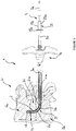
- FIG. 1 a spinal segment Sr of a spine whose vertebrae Va, Vb and the intervertebral disc Di are pierced and / or milled by a flexible and cannulated cutting device 1 according to the present invention.
- the cutting device 1 Prior to the installation of the cutting device 1, it is anchored for example in the lower vertebra Vb a right trocar Tr allowing the guiding of said cutting device 1 in the horizontal and right drilling part of said vertebra Va.
- the cutting device 1 consists of a flexible and cannulated cutting element 2 and a guide element 3 with a curved profile ensuring the positioning and angular deformation of the cutting element 2 inside the bone tissues and / or conjunctives.
- the guide element 3 of the cutting device 1 consists of a rod 3a made of Nitinol having a small diameter and an end with a curved profile 3b of predetermined radius ending in a tapered tip 3c.
- the guide element 3 is made of a hyper elastic material ensuring an elastic deformation of the end with a curved profile 3b in order to allow its introduction into the right trocar Tr.
- the flexible and cannulated cutting element 2 of the cutting device 1 consists of a rigid tube 20 integral at one of its ends with a flexible and flexible connection 21 extending by a cannulated burr 22 and at the end opposite a safety connector 23 allowing the connection with not shown drive means.
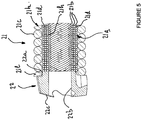
- the flexible and flexible connection 21 consists of a hollow strand 21a with fibers or helical son 21d around which is arranged a protective sheath 21c which are respectively assembled to the cannulated burr 22 on the one hand and to the rigid tube 20 on the other go.
- the hollow strand 21a consists of an arrangement of at least three layers 21b of fibers or helical wires 21d arranged in a staggered manner delimiting an internal bore 21h.
- Each layer 21b is formed of at least eighteen fibers or threads 21d arranged regularly on the circular periphery of the strand 21a in a helical profile along the longitudinal axis of said strand.
- the first and the third layer 21b are arranged along the longitudinal axis of the strand 21a in the same first helical direction, while the second layer 21b interposed between the first and the third is directed in a second helical direction which intersects said first helical steering.
- Each fiber or son 21d of each layer 21b of the hollow strand 21a has the same external diameter.
- the hollow strand 21a cooperates at one of its ends with the vertical edge of a first cylindrical part 21f of a tubular spacer 21e on which are welded the free ends of the fibers or helical son 21d of the three layers 21b arranged in staggered rows.
- the hollow strand 21a is positioned in the extension of the first cylindrical part 21f of the spacer 21e so that the internal bores 21h and 21j are respectively coaxial.
- the spacer 21e comprises in the extension of the first cylindrical part 21f a second cylindrical part 21g whose external diameter is greater than that of said first in order to cooperate with the internal bore of the rigid tube 20.
- the second cylindrical part 21g of the spacer 21e is immobilized in translation and in rotation inside the rigid tube 20 by any fixing means such as for example by welding and / or by axial deformation of the outer wall of said tube.
- the other free ends of the fibers or helical threads 21d of the three layers 21b arranged staggered from the hollow strand 21a opposite those integral with the spacer 21e are fixed by welding to the vertical edge of a shoulder 22a of the cannulated burr 22.
- the hollow strand 21a is positioned relative to the cannulated burr 22 so that the internal bores 21h and 22b are respectively in the extension of one another.
- the protective sheath 21c of the flexible and flexible connection 21 consists of a spring 21k with adjoining turns 21l enveloping the outer face of the fibers or helical son 21d of the hollow strand 21a and each end of which is respectively secured to the rigid tube 20 and cannulated bur 22.
- the first free end of the spring 21k is secured to the rigid tube 20 by welding the first coil 21l to the vertical edge of the free end of said tube.
- the second free end of the spring 21k is integral with the cannulated burr 22 by welding the last turn 21l on the outer periphery of the shoulder 22a near the area of attachment of the hollow strand 21 on this same shoulder.
- the protective sheath 21c may consist of a flexible polymer sheath, each end of which can be fixed directly or indirectly on the rigid tube 20 and the cannulated burr 22.
- the cannulated burr 22 of the flexible cutting element 2 has at least three teeth 22c regularly distributed around the internal bore 22b and whose cutting profile respectively ensures a swallowing of material causing during the rotation of the drive device. cuts 1 its advancement in bone or connective tissue.
- the cannulated and swallowing cutter 22 makes it possible to reduce the compressive stresses transmitted to the flexible and flexible connection 21 during drilling or milling.
- the cutting angles of the teeth 22c are adapted in order to reduce the axial compressive forces during the removal of bone or connective tissue.
- the safety connector 23 of the flexible and cannulated cutting element 2 has a breaking torque which is lower than that of the flexible and flexible connection 21 with the rigid tube 20 ensuring a disconnection of said cutting device 1 with the means of training when the cannulated bur 22 encounters dense tissue causing an increase in the resistance torque.
- the safety connector 23 consists of a cylindrical sleeve 23a integral at one of its ends with a collar 23b.
- the sleeve 23a has an internal diameter making it possible to receive the external one of the rigid tube 20.
- the safety connector 23 is made integral with the rigid tube 20 by means of a pin 23c passing through the sleeve 23a and said tube.
- the pin 23c is calibrated to break under a torque which is less than that of the flexible and flexible connection 21 with the rigid tube 20.
- the structural arrangement of the flexible and cannulated cutting element 2 and the way in which the ends of the flexible and flexible connection 21 are fixed to the rigid tube 20 and to the cannulated bur 22 allows on the one hand that the hollow strand 21a transmits the torque itself along the curved guide element 3 and on the other hand that the protective sheath 21c is subjected to axial and radial forces without breaking.
Landscapes
- Health & Medical Sciences (AREA)
- Surgery (AREA)
- Life Sciences & Earth Sciences (AREA)
- Biomedical Technology (AREA)
- Medical Informatics (AREA)
- Orthopedic Medicine & Surgery (AREA)
- Oral & Maxillofacial Surgery (AREA)
- Engineering & Computer Science (AREA)
- Dentistry (AREA)
- Heart & Thoracic Surgery (AREA)
- Nuclear Medicine, Radiotherapy & Molecular Imaging (AREA)
- Molecular Biology (AREA)
- Animal Behavior & Ethology (AREA)
- General Health & Medical Sciences (AREA)
- Public Health (AREA)
- Veterinary Medicine (AREA)
- Surgical Instruments (AREA)
- Prostheses (AREA)
Claims (10)
- Flexible und kanülierte Schneidvorrichtung zum Bohren und/oder Fräsen eines Raums in Knochen- oder Bindegeweben, wobei die Vorrichtung
einerseits ein Schneidelement (2), das aus einem starren Rohr (20) besteht, das an einem seiner Enden mit einer biegsamen und flexiblen Verbindung (21), die sich durch einen kanülierten Fräser (22) erstreckt, und am gegenüberliegenden Ende mit Antriebsmitteln fest verbunden ist, die mit einem Sicherheitsverbinder (23) zum Lösen der Schneidvorrichtung versehen sind,
und andererseits ein Führungselement (3) aufweist, das das Positionieren und die Winkelverformung des Schneidelements (2) im Inneren der Knochen- oder Bindegewebe sicherstellt, dadurch gekennzeichnet, dass die biegsame und flexible Verbindung (21) des Schneidelements (2) aus einem Hohlstrang (21a) mit Fasern oder schraubenförmig gewickelten Drähten (21d) besteht, um den eine Schutzhülle (21c) angeordnet ist, wobei der Strang (21a) und die Schutzhülle (21c) jeweils an dem kanülierten Fräser (22) und an dem starren Rohr (20) angebracht sind. - Flexible und kanülierte Schneidvorrichtung nach Anspruch 2, dadurch gekennzeichnet, dass der Hohlstrang (21a) aus einer Anordnung von mindestens drei Schichten (21b) von Fasern oder schraubenförmig gewickelten Drähten (21d) gebildet ist, die versetzt angeordnet sind, die eine innere Bohrung (21h) begrenzen.
- Flexible und kanülierte Schneidvorrichtung nach Anspruch 3, dadurch gekennzeichnet, dass jede Schicht (21b) aus mindestens achtzehn Fasern oder Drähten (21d) gebildet ist, die regelmäßig am kreisförmigen Umfang des Strangs (21a) in einem spiralförmigen Profil entlang der Längsachse des Strangs angeordnet sind.
- Flexible und kanülierte Schneidvorrichtung nach Anspruch 3, dadurch gekennzeichnet, dass die erste und die dritte Schicht (21b) entlang der Längsachse des Strangs (21a) in der gleichen ersten spiralförmigen Richtung angeordnet sind, während die zweite Schicht (21b), die zwischen der ersten und der dritten angeordnet ist, in eine zweite spiralförmige Richtung gerichtet ist, die die erste spiralförmige Richtung schneidet.
- Flexible und kanülierte Schneidvorrichtung nach Anspruch 3, dadurch gekennzeichnet, dass der Hohlstrang (21a) an einem seiner Enden an der vertikalen Kante eines ersten zylindrischen Teils (21f) eines röhrenförmigen Abstandshalters (21e) befestigt ist, der mit dem starren Rohr (20) fest verbunden ist, während das andere Ende an der vertikalen Kante einer Schulter (22a) des kanülierten Fräsers (22) angebracht ist.
- Flexible und kanülierte Schneidvorrichtung nach Anspruch 2, dadurch gekennzeichnet, dass die Schutzhülle (21c) der biegsamen und flexiblen Verbindung (21) aus einer Feder (21k) mit aneinander liegenden Windungen (211) besteht, die die Außenseite der Fasern oder schraubenförmig gewickelten Drähte (21d) des Hohlstrangs (21a) umhüllen und wovon jedes Ende jeweils mit dem starren Rohr (20) und des kanülierten Fräsers (22) fest verbunden ist.
- Flexible und kanülierte Schneidvorrichtung nach Anspruch 2, dadurch gekennzeichnet, dass die Schutzhülle (21c) aus einer flexiblen Polymerhülle bestehen kann, wovon jedes Ende direkt oder indirekt an dem starren Rohr (20) und dem kanülierten Fräser (22) befestigt werden kann.
- Flexible und kanülierte Schneidvorrichtung nach Anspruch 1, dadurch gekennzeichnet, dass der kanülierte Fräser (22) des flexiblen Schneidelements (2) mindestens drei Zähne (22c) aufweist, die regelmäßig um eine Innenbohrung (22b) verteilt sind und deren Schnittprofil jeweils ein Einziehen von Material gewährleistet, wodurch während des Indrehungversetzens der Schneidvorrichtung (1) ihr Vorschub in die Knochen- oder Bindegewebe bewirkt wird.
- Flexible und kanülierte Schneidvorrichtung nach Anspruch 1, dadurch gekennzeichnet, dass der Sicherheitsverbinder (23) mit dem starren Rohr (20) über einen Stift (23c) fest verbunden ist, der kalibriert ist, um bei einem Drehmoment zu brechen, das niedriger ist als jenes der biegsamen und flexiblen Verbindung (21) mit dem starren Rohr (20).
- Flexible und kanülierte Schneidvorrichtung nach Anspruch 1, dadurch gekennzeichnet, dass das Führungselement (3) aus einer Stange (3a) besteht, die aus Nitinol hergestellt ist, die einen kleinen Durchmesser und ein Ende mit einem gekrümmten Profil (3b) mit einem vorbestimmten Radius aufweist, die in einer sich verjüngenden Spitze (3c) endet.
Applications Claiming Priority (2)
| Application Number | Priority Date | Filing Date | Title |
|---|---|---|---|
| FR1650369A FR3046724B1 (fr) | 2016-01-18 | 2016-01-18 | Fraise flexible canulee |
| PCT/FR2017/050085 WO2017125667A1 (fr) | 2016-01-18 | 2017-01-13 | Dispositif de coupe flexible et canule |
Publications (2)
| Publication Number | Publication Date |
|---|---|
| EP3407807A1 EP3407807A1 (de) | 2018-12-05 |
| EP3407807B1 true EP3407807B1 (de) | 2020-10-07 |
Family
ID=55451455
Family Applications (1)
| Application Number | Title | Priority Date | Filing Date |
|---|---|---|---|
| EP17706531.5A Active EP3407807B1 (de) | 2016-01-18 | 2017-01-13 | Flexible und kanülierte schneidvorrichtung |
Country Status (4)
| Country | Link |
|---|---|
| US (1) | US10383641B2 (de) |
| EP (1) | EP3407807B1 (de) |
| FR (1) | FR3046724B1 (de) |
| WO (1) | WO2017125667A1 (de) |
Families Citing this family (16)
| Publication number | Priority date | Publication date | Assignee | Title |
|---|---|---|---|---|
| US8361067B2 (en) | 2002-09-30 | 2013-01-29 | Relievant Medsystems, Inc. | Methods of therapeutically heating a vertebral body to treat back pain |
| JP5688022B2 (ja) | 2008-09-26 | 2015-03-25 | リリーバント メドシステムズ、インコーポレイテッド | 骨の内部を通って器具を誘導するためのシステムおよび方法 |
| US10028753B2 (en) | 2008-09-26 | 2018-07-24 | Relievant Medsystems, Inc. | Spine treatment kits |
| US10390877B2 (en) | 2011-12-30 | 2019-08-27 | Relievant Medsystems, Inc. | Systems and methods for treating back pain |
| US10588691B2 (en) | 2012-09-12 | 2020-03-17 | Relievant Medsystems, Inc. | Radiofrequency ablation of tissue within a vertebral body |
| AU2013337680B2 (en) | 2012-11-05 | 2019-04-18 | Relievant Medsystems, Inc. | Systems and methods for creating curved paths through bone and modulating nerves within the bone |
| US9724151B2 (en) | 2013-08-08 | 2017-08-08 | Relievant Medsystems, Inc. | Modulating nerves within bone using bone fasteners |
| EP3226787B1 (de) | 2014-12-02 | 2025-04-16 | Conventus Orthopedics, Inc. | Aktivkompressionsvorrichtungen undverfahren zur montage |
| US11224467B2 (en) | 2016-02-26 | 2022-01-18 | Activortho, Inc. | Active compression apparatus, methods of assembly and methods of use |
| JP7084879B2 (ja) | 2016-02-26 | 2022-06-15 | アクティボーソ, インコーポレイテッド | 能動的圧縮装置、組み立ての方法、および使用の方法 |
| US11446073B2 (en) * | 2019-08-26 | 2022-09-20 | DePuy Synthes Products, Inc. | Flexible shaft support rod |
| WO2021050767A1 (en) | 2019-09-12 | 2021-03-18 | Relievant Medsystems, Inc. | Systems and methods for tissue modulation |
| AU2021306313A1 (en) | 2020-07-10 | 2023-03-02 | Relievant Medsystems, Inc. | Vertebral denervation in conjunction with vertebral fusion |
| US12082876B1 (en) | 2020-09-28 | 2024-09-10 | Relievant Medsystems, Inc. | Introducer drill |
| EP4268150A4 (de) | 2020-12-22 | 2024-12-18 | Relievant Medsystems, Inc. | Vorhersage von kandidaten für die spinale neuromodulation |
| US12433668B1 (en) | 2021-11-08 | 2025-10-07 | Relievant Medsystems, Inc. | Impedance stoppage mitigation during radiofrequency tissue ablation procedures |
Family Cites Families (13)
| Publication number | Priority date | Publication date | Assignee | Title |
|---|---|---|---|---|
| US7258692B2 (en) * | 2000-03-07 | 2007-08-21 | Zimmer, Inc. | Method and apparatus for reducing femoral fractures |
| US20070093840A1 (en) * | 2005-10-06 | 2007-04-26 | Pacelli Nicolas J | Flexible shaft |
| WO2009155319A1 (en) * | 2008-06-17 | 2009-12-23 | Soteira, Inc. | Devices and methods for fracture reduction |
| US8556911B2 (en) * | 2009-01-27 | 2013-10-15 | Vishal M. Mehta | Arthroscopic tunnel guide for rotator cuff repair |
| WO2010111246A1 (en) * | 2009-03-23 | 2010-09-30 | Soteira, Inc. | Devices and methods for vertebrostenting |
| AU2011312049B2 (en) * | 2010-10-06 | 2015-06-18 | Smith & Nephew, Inc. | A system for use in tissue repair |
| EP2672901A1 (de) * | 2011-02-08 | 2013-12-18 | Howmedica Osteonics Corp. | Flexible mikrobohrinstrumente, kits und verfahren |
| CA3201083A1 (en) * | 2012-06-20 | 2013-12-27 | Stryker Corporation | Systems and methods for off-axis tissue manipulation |
| EP2919689B1 (de) * | 2012-11-14 | 2018-06-13 | British Columbia Cancer Agency Branch | Kanülierte bohrhammerbefestigung |
| US9642629B2 (en) * | 2012-11-20 | 2017-05-09 | Specialty Surgical Instrumentation Inc. | System and method for forming a curved tunnel in bone |
| US20150141998A1 (en) * | 2013-11-19 | 2015-05-21 | Symmetry Medical Manufacturing, Inc | System and method for forming a curved tunnel in bone |
| US10751193B2 (en) * | 2015-04-16 | 2020-08-25 | Clariance | Device for percutaneous transpedicular fusion |
| US10653431B2 (en) * | 2016-06-14 | 2020-05-19 | Medos International Sarl | Drill assemblies and methods for drilling into bone |
-
2016
- 2016-01-18 FR FR1650369A patent/FR3046724B1/fr active Active
-
2017
- 2017-01-13 WO PCT/FR2017/050085 patent/WO2017125667A1/fr not_active Ceased
- 2017-01-13 EP EP17706531.5A patent/EP3407807B1/de active Active
- 2017-01-17 US US15/407,880 patent/US10383641B2/en active Active
Non-Patent Citations (1)
| Title |
|---|
| None * |
Also Published As
| Publication number | Publication date |
|---|---|
| US10383641B2 (en) | 2019-08-20 |
| FR3046724B1 (fr) | 2021-03-05 |
| WO2017125667A1 (fr) | 2017-07-27 |
| FR3046724A1 (fr) | 2017-07-21 |
| EP3407807A1 (de) | 2018-12-05 |
| US20170202563A1 (en) | 2017-07-20 |
Similar Documents
| Publication | Publication Date | Title |
|---|---|---|
| WO2017125667A1 (fr) | Dispositif de coupe flexible et canule | |
| EP2667796B1 (de) | Bohrvorrichtung zur herstellung eines knochenkanals mit gewölbtem profil in einem wirbelkörper | |
| EP1532930B1 (de) | Wiederlösbarer Spreizanker für chirurgischen Nähfaden | |
| EP1273272B1 (de) | Befestigungsvorrichtung für Knochenteile | |
| EP2327366B1 (de) | Besteck zum Bohren des Herzseptums und Implantieren einer transseptalen Sonde, insbesondere einer Sonde zum Feststellen/Stimulieren einer Vertiefung links vom Herzen | |
| EP2493397B1 (de) | Antriebswelle für einen chirurgischen Fräser | |
| CN104768478B (zh) | 组织移除装置 | |
| CA2362247C (fr) | Dispositif de distraction/contraction pour systeme d'osteosynthese rachidienne | |
| WO1999053843A1 (fr) | Dispositif de fixation reversible pour la mise en place d'un implant dans l'os | |
| EP0180532B1 (de) | Koaptor für Frakturen des Oberschenkelhalses und dergleichen | |
| FR2787313A1 (fr) | Implant d'osteosynthese | |
| EP1046376A1 (de) | Kompressionsknochenschraube und Hilfinstrumente zu ihrer Befestigung | |
| FR3013958A1 (fr) | Trocart a biopsie. | |
| EP2818126B1 (de) | Fräserhalter mit Griff | |
| FR2777444A1 (fr) | Ancre de suture vissee | |
| US10779871B2 (en) | Flexible surgical screw driver | |
| FR2971138A1 (fr) | Prothese d'osteosynthese destinee a la reduction des fractures non deplacees | |
| EP3376982A1 (de) | Knochenschraube mit doppelgewinde | |
| CA2521793A1 (fr) | Instrument pour l'alesage de canaux radiculaires | |
| KR101429395B1 (ko) | 관절부위용 천공기구 | |
| CN217566204U (zh) | 一种可变向脊柱磨头 | |
| FR2930422A1 (fr) | Gaine de protection d'un foret pour instrument chirurgical, munie d'un canal d'acheminement d'un fluide d'irrigation vers la partie tranchante du foret | |
| EP2874573B1 (de) | Antriebsanordnung für eine schneideeinheit eines rasierapparats | |
| US20240008915A1 (en) | Heart valve ablation catheter | |
| EP3854340B1 (de) | Hilfsvorrichtung für die implantation einer knochenschraube in das knochenmedium eines lebewesens |
Legal Events
| Date | Code | Title | Description |
|---|---|---|---|
| STAA | Information on the status of an ep patent application or granted ep patent |
Free format text: STATUS: UNKNOWN |
|
| STAA | Information on the status of an ep patent application or granted ep patent |
Free format text: STATUS: THE INTERNATIONAL PUBLICATION HAS BEEN MADE |
|
| PUAI | Public reference made under article 153(3) epc to a published international application that has entered the european phase |
Free format text: ORIGINAL CODE: 0009012 |
|
| STAA | Information on the status of an ep patent application or granted ep patent |
Free format text: STATUS: REQUEST FOR EXAMINATION WAS MADE |
|
| 17P | Request for examination filed |
Effective date: 20180723 |
|
| AK | Designated contracting states |
Kind code of ref document: A1 Designated state(s): AL AT BE BG CH CY CZ DE DK EE ES FI FR GB GR HR HU IE IS IT LI LT LU LV MC MK MT NL NO PL PT RO RS SE SI SK SM TR |
|
| AX | Request for extension of the european patent |
Extension state: BA ME |
|
| DAV | Request for validation of the european patent (deleted) | ||
| DAX | Request for extension of the european patent (deleted) | ||
| GRAP | Despatch of communication of intention to grant a patent |
Free format text: ORIGINAL CODE: EPIDOSNIGR1 |
|
| STAA | Information on the status of an ep patent application or granted ep patent |
Free format text: STATUS: GRANT OF PATENT IS INTENDED |
|
| INTG | Intention to grant announced |
Effective date: 20200507 |
|
| GRAS | Grant fee paid |
Free format text: ORIGINAL CODE: EPIDOSNIGR3 |
|
| GRAA | (expected) grant |
Free format text: ORIGINAL CODE: 0009210 |
|
| STAA | Information on the status of an ep patent application or granted ep patent |
Free format text: STATUS: THE PATENT HAS BEEN GRANTED |
|
| AK | Designated contracting states |
Kind code of ref document: B1 Designated state(s): AL AT BE BG CH CY CZ DE DK EE ES FI FR GB GR HR HU IE IS IT LI LT LU LV MC MK MT NL NO PL PT RO RS SE SI SK SM TR |
|
| REG | Reference to a national code |
Ref country code: GB Ref legal event code: FG4D Free format text: NOT ENGLISH |
|
| REG | Reference to a national code |
Ref country code: AT Ref legal event code: REF Ref document number: 1320323 Country of ref document: AT Kind code of ref document: T Effective date: 20201015 Ref country code: CH Ref legal event code: EP |
|
| REG | Reference to a national code |
Ref country code: IE Ref legal event code: FG4D Free format text: LANGUAGE OF EP DOCUMENT: FRENCH |
|
| REG | Reference to a national code |
Ref country code: DE Ref legal event code: R096 Ref document number: 602017024980 Country of ref document: DE |
|
| REG | Reference to a national code |
Ref country code: NL Ref legal event code: MP Effective date: 20201007 |
|
| REG | Reference to a national code |
Ref country code: AT Ref legal event code: MK05 Ref document number: 1320323 Country of ref document: AT Kind code of ref document: T Effective date: 20201007 |
|
| PG25 | Lapsed in a contracting state [announced via postgrant information from national office to epo] |
Ref country code: NO Free format text: LAPSE BECAUSE OF FAILURE TO SUBMIT A TRANSLATION OF THE DESCRIPTION OR TO PAY THE FEE WITHIN THE PRESCRIBED TIME-LIMIT Effective date: 20210107 Ref country code: PT Free format text: LAPSE BECAUSE OF FAILURE TO SUBMIT A TRANSLATION OF THE DESCRIPTION OR TO PAY THE FEE WITHIN THE PRESCRIBED TIME-LIMIT Effective date: 20210208 Ref country code: RS Free format text: LAPSE BECAUSE OF FAILURE TO SUBMIT A TRANSLATION OF THE DESCRIPTION OR TO PAY THE FEE WITHIN THE PRESCRIBED TIME-LIMIT Effective date: 20201007 Ref country code: FI Free format text: LAPSE BECAUSE OF FAILURE TO SUBMIT A TRANSLATION OF THE DESCRIPTION OR TO PAY THE FEE WITHIN THE PRESCRIBED TIME-LIMIT Effective date: 20201007 Ref country code: GR Free format text: LAPSE BECAUSE OF FAILURE TO SUBMIT A TRANSLATION OF THE DESCRIPTION OR TO PAY THE FEE WITHIN THE PRESCRIBED TIME-LIMIT Effective date: 20210108 |
|
| REG | Reference to a national code |
Ref country code: LT Ref legal event code: MG4D |
|
| PG25 | Lapsed in a contracting state [announced via postgrant information from national office to epo] |
Ref country code: AT Free format text: LAPSE BECAUSE OF FAILURE TO SUBMIT A TRANSLATION OF THE DESCRIPTION OR TO PAY THE FEE WITHIN THE PRESCRIBED TIME-LIMIT Effective date: 20201007 Ref country code: ES Free format text: LAPSE BECAUSE OF FAILURE TO SUBMIT A TRANSLATION OF THE DESCRIPTION OR TO PAY THE FEE WITHIN THE PRESCRIBED TIME-LIMIT Effective date: 20201007 Ref country code: BG Free format text: LAPSE BECAUSE OF FAILURE TO SUBMIT A TRANSLATION OF THE DESCRIPTION OR TO PAY THE FEE WITHIN THE PRESCRIBED TIME-LIMIT Effective date: 20210107 Ref country code: IS Free format text: LAPSE BECAUSE OF FAILURE TO SUBMIT A TRANSLATION OF THE DESCRIPTION OR TO PAY THE FEE WITHIN THE PRESCRIBED TIME-LIMIT Effective date: 20210207 Ref country code: LV Free format text: LAPSE BECAUSE OF FAILURE TO SUBMIT A TRANSLATION OF THE DESCRIPTION OR TO PAY THE FEE WITHIN THE PRESCRIBED TIME-LIMIT Effective date: 20201007 Ref country code: PL Free format text: LAPSE BECAUSE OF FAILURE TO SUBMIT A TRANSLATION OF THE DESCRIPTION OR TO PAY THE FEE WITHIN THE PRESCRIBED TIME-LIMIT Effective date: 20201007 Ref country code: SE Free format text: LAPSE BECAUSE OF FAILURE TO SUBMIT A TRANSLATION OF THE DESCRIPTION OR TO PAY THE FEE WITHIN THE PRESCRIBED TIME-LIMIT Effective date: 20201007 |
|
| PG25 | Lapsed in a contracting state [announced via postgrant information from national office to epo] |
Ref country code: NL Free format text: LAPSE BECAUSE OF FAILURE TO SUBMIT A TRANSLATION OF THE DESCRIPTION OR TO PAY THE FEE WITHIN THE PRESCRIBED TIME-LIMIT Effective date: 20201007 Ref country code: HR Free format text: LAPSE BECAUSE OF FAILURE TO SUBMIT A TRANSLATION OF THE DESCRIPTION OR TO PAY THE FEE WITHIN THE PRESCRIBED TIME-LIMIT Effective date: 20201007 |
|
| REG | Reference to a national code |
Ref country code: DE Ref legal event code: R097 Ref document number: 602017024980 Country of ref document: DE |
|
| PG25 | Lapsed in a contracting state [announced via postgrant information from national office to epo] |
Ref country code: LT Free format text: LAPSE BECAUSE OF FAILURE TO SUBMIT A TRANSLATION OF THE DESCRIPTION OR TO PAY THE FEE WITHIN THE PRESCRIBED TIME-LIMIT Effective date: 20201007 Ref country code: CZ Free format text: LAPSE BECAUSE OF FAILURE TO SUBMIT A TRANSLATION OF THE DESCRIPTION OR TO PAY THE FEE WITHIN THE PRESCRIBED TIME-LIMIT Effective date: 20201007 Ref country code: EE Free format text: LAPSE BECAUSE OF FAILURE TO SUBMIT A TRANSLATION OF THE DESCRIPTION OR TO PAY THE FEE WITHIN THE PRESCRIBED TIME-LIMIT Effective date: 20201007 Ref country code: SM Free format text: LAPSE BECAUSE OF FAILURE TO SUBMIT A TRANSLATION OF THE DESCRIPTION OR TO PAY THE FEE WITHIN THE PRESCRIBED TIME-LIMIT Effective date: 20201007 Ref country code: RO Free format text: LAPSE BECAUSE OF FAILURE TO SUBMIT A TRANSLATION OF THE DESCRIPTION OR TO PAY THE FEE WITHIN THE PRESCRIBED TIME-LIMIT Effective date: 20201007 Ref country code: SK Free format text: LAPSE BECAUSE OF FAILURE TO SUBMIT A TRANSLATION OF THE DESCRIPTION OR TO PAY THE FEE WITHIN THE PRESCRIBED TIME-LIMIT Effective date: 20201007 |
|
| REG | Reference to a national code |
Ref country code: DE Ref legal event code: R119 Ref document number: 602017024980 Country of ref document: DE |
|
| PLBE | No opposition filed within time limit |
Free format text: ORIGINAL CODE: 0009261 |
|
| STAA | Information on the status of an ep patent application or granted ep patent |
Free format text: STATUS: NO OPPOSITION FILED WITHIN TIME LIMIT |
|
| PG25 | Lapsed in a contracting state [announced via postgrant information from national office to epo] |
Ref country code: MC Free format text: LAPSE BECAUSE OF FAILURE TO SUBMIT A TRANSLATION OF THE DESCRIPTION OR TO PAY THE FEE WITHIN THE PRESCRIBED TIME-LIMIT Effective date: 20201007 Ref country code: DK Free format text: LAPSE BECAUSE OF FAILURE TO SUBMIT A TRANSLATION OF THE DESCRIPTION OR TO PAY THE FEE WITHIN THE PRESCRIBED TIME-LIMIT Effective date: 20201007 |
|
| REG | Reference to a national code |
Ref country code: CH Ref legal event code: PL |
|
| 26N | No opposition filed |
Effective date: 20210708 |
|
| GBPC | Gb: european patent ceased through non-payment of renewal fee |
Effective date: 20210113 |
|
| PG25 | Lapsed in a contracting state [announced via postgrant information from national office to epo] |
Ref country code: LU Free format text: LAPSE BECAUSE OF NON-PAYMENT OF DUE FEES Effective date: 20210113 |
|
| REG | Reference to a national code |
Ref country code: BE Ref legal event code: MM Effective date: 20210131 |
|
| PG25 | Lapsed in a contracting state [announced via postgrant information from national office to epo] |
Ref country code: AL Free format text: LAPSE BECAUSE OF FAILURE TO SUBMIT A TRANSLATION OF THE DESCRIPTION OR TO PAY THE FEE WITHIN THE PRESCRIBED TIME-LIMIT Effective date: 20201007 Ref country code: IT Free format text: LAPSE BECAUSE OF FAILURE TO SUBMIT A TRANSLATION OF THE DESCRIPTION OR TO PAY THE FEE WITHIN THE PRESCRIBED TIME-LIMIT Effective date: 20201007 |
|
| PG25 | Lapsed in a contracting state [announced via postgrant information from national office to epo] |
Ref country code: LI Free format text: LAPSE BECAUSE OF NON-PAYMENT OF DUE FEES Effective date: 20210131 Ref country code: GB Free format text: LAPSE BECAUSE OF NON-PAYMENT OF DUE FEES Effective date: 20210113 Ref country code: DE Free format text: LAPSE BECAUSE OF NON-PAYMENT OF DUE FEES Effective date: 20210803 Ref country code: CH Free format text: LAPSE BECAUSE OF NON-PAYMENT OF DUE FEES Effective date: 20210131 Ref country code: SI Free format text: LAPSE BECAUSE OF FAILURE TO SUBMIT A TRANSLATION OF THE DESCRIPTION OR TO PAY THE FEE WITHIN THE PRESCRIBED TIME-LIMIT Effective date: 20201007 |
|
| PG25 | Lapsed in a contracting state [announced via postgrant information from national office to epo] |
Ref country code: IE Free format text: LAPSE BECAUSE OF NON-PAYMENT OF DUE FEES Effective date: 20210113 |
|
| PG25 | Lapsed in a contracting state [announced via postgrant information from national office to epo] |
Ref country code: IS Free format text: LAPSE BECAUSE OF FAILURE TO SUBMIT A TRANSLATION OF THE DESCRIPTION OR TO PAY THE FEE WITHIN THE PRESCRIBED TIME-LIMIT Effective date: 20210207 |
|
| PG25 | Lapsed in a contracting state [announced via postgrant information from national office to epo] |
Ref country code: BE Free format text: LAPSE BECAUSE OF NON-PAYMENT OF DUE FEES Effective date: 20210131 |
|
| PG25 | Lapsed in a contracting state [announced via postgrant information from national office to epo] |
Ref country code: CY Free format text: LAPSE BECAUSE OF FAILURE TO SUBMIT A TRANSLATION OF THE DESCRIPTION OR TO PAY THE FEE WITHIN THE PRESCRIBED TIME-LIMIT Effective date: 20201007 |
|
| PG25 | Lapsed in a contracting state [announced via postgrant information from national office to epo] |
Ref country code: HU Free format text: LAPSE BECAUSE OF FAILURE TO SUBMIT A TRANSLATION OF THE DESCRIPTION OR TO PAY THE FEE WITHIN THE PRESCRIBED TIME-LIMIT; INVALID AB INITIO Effective date: 20170113 |
|
| PG25 | Lapsed in a contracting state [announced via postgrant information from national office to epo] |
Ref country code: MK Free format text: LAPSE BECAUSE OF FAILURE TO SUBMIT A TRANSLATION OF THE DESCRIPTION OR TO PAY THE FEE WITHIN THE PRESCRIBED TIME-LIMIT Effective date: 20201007 |
|
| PG25 | Lapsed in a contracting state [announced via postgrant information from national office to epo] |
Ref country code: TR Free format text: LAPSE BECAUSE OF FAILURE TO SUBMIT A TRANSLATION OF THE DESCRIPTION OR TO PAY THE FEE WITHIN THE PRESCRIBED TIME-LIMIT Effective date: 20201007 |
|
| PG25 | Lapsed in a contracting state [announced via postgrant information from national office to epo] |
Ref country code: MT Free format text: LAPSE BECAUSE OF FAILURE TO SUBMIT A TRANSLATION OF THE DESCRIPTION OR TO PAY THE FEE WITHIN THE PRESCRIBED TIME-LIMIT Effective date: 20201007 |
|
| PGFP | Annual fee paid to national office [announced via postgrant information from national office to epo] |
Ref country code: FR Payment date: 20250127 Year of fee payment: 9 |