EP2874573B1 - Antriebsanordnung für eine schneideeinheit eines rasierapparats - Google Patents
Antriebsanordnung für eine schneideeinheit eines rasierapparats Download PDFInfo
- Publication number
- EP2874573B1 EP2874573B1 EP13747437.5A EP13747437A EP2874573B1 EP 2874573 B1 EP2874573 B1 EP 2874573B1 EP 13747437 A EP13747437 A EP 13747437A EP 2874573 B1 EP2874573 B1 EP 2874573B1
- Authority
- EP
- European Patent Office
- Prior art keywords
- cutting tool
- nucleotomy
- tool holder
- main body
- hand
- Prior art date
- Legal status (The legal status is an assumption and is not a legal conclusion. Google has not performed a legal analysis and makes no representation as to the accuracy of the status listed.)
- Not-in-force
Links
Images











Classifications
-
- A—HUMAN NECESSITIES
- A61—MEDICAL OR VETERINARY SCIENCE; HYGIENE
- A61B—DIAGNOSIS; SURGERY; IDENTIFICATION
- A61B17/00—Surgical instruments, devices or methods
- A61B17/16—Instruments for performing osteoclasis; Drills or chisels for bones; Trepans
- A61B17/1613—Component parts
- A61B17/1615—Drill bits, i.e. rotating tools extending from a handpiece to contact the worked material
- A61B17/1617—Drill bits, i.e. rotating tools extending from a handpiece to contact the worked material with mobile or detachable parts
-
- A—HUMAN NECESSITIES
- A61—MEDICAL OR VETERINARY SCIENCE; HYGIENE
- A61B—DIAGNOSIS; SURGERY; IDENTIFICATION
- A61B17/00—Surgical instruments, devices or methods
- A61B17/16—Instruments for performing osteoclasis; Drills or chisels for bones; Trepans
- A61B17/1613—Component parts
- A61B17/1622—Drill handpieces
-
- A—HUMAN NECESSITIES
- A61—MEDICAL OR VETERINARY SCIENCE; HYGIENE
- A61B—DIAGNOSIS; SURGERY; IDENTIFICATION
- A61B17/00—Surgical instruments, devices or methods
- A61B17/16—Instruments for performing osteoclasis; Drills or chisels for bones; Trepans
- A61B17/1613—Component parts
- A61B17/1631—Special drive shafts, e.g. flexible shafts
-
- A—HUMAN NECESSITIES
- A61—MEDICAL OR VETERINARY SCIENCE; HYGIENE
- A61B—DIAGNOSIS; SURGERY; IDENTIFICATION
- A61B17/00—Surgical instruments, devices or methods
- A61B17/32—Surgical cutting instruments
- A61B17/320016—Endoscopic cutting instruments, e.g. arthroscopes, resectoscopes
- A61B17/32002—Endoscopic cutting instruments, e.g. arthroscopes, resectoscopes with continuously rotating, oscillating or reciprocating cutting instruments
-
- A—HUMAN NECESSITIES
- A61—MEDICAL OR VETERINARY SCIENCE; HYGIENE
- A61B—DIAGNOSIS; SURGERY; IDENTIFICATION
- A61B17/00—Surgical instruments, devices or methods
- A61B17/00234—Surgical instruments, devices or methods for minimally invasive surgery
- A61B2017/00238—Type of minimally invasive operation
- A61B2017/00261—Discectomy
-
- A—HUMAN NECESSITIES
- A61—MEDICAL OR VETERINARY SCIENCE; HYGIENE
- A61B—DIAGNOSIS; SURGERY; IDENTIFICATION
- A61B2217/00—General characteristics of surgical instruments
- A61B2217/002—Auxiliary appliance
- A61B2217/005—Auxiliary appliance with suction drainage system
Definitions
- the present invention relates to a nucleotomy device allowing, from a transosseous approach previously pierced in the body of a vertebra, the production in an intervertebral disc of a nucleic space.
- the document US2010 / 0217245 describes a medical instrument comprising means for transmitting the rotary movement from the motor to a tool and the arrangement of magnets which only allow the tool to be driven in rotation and in a direction opposite to that of the motor.
- the object of the nucleotomy apparatus according to the present invention is to enable the surgeon to produce, after the drilling of one or two channels inside the body of the vertebra, of a nucleic space for the establishment of a nucleic acid implant ensuring the repair of the damaged intervertebral disc.
- the nucleotomy apparatus comprises a tool holder provided with first connection means ensuring the installation of an electric motor with rotary drive, second connection means for the installation of a cutting tool. blade, drive means providing the cutting tool with rotational and longitudinal translational movements and injection and suction means making it possible to evacuate the debris from the core resulting from the cutting during its installation in the inside the intervertebral disc.
- the nucleotomy apparatus comprises adjustment means limiting the travel path in translation of the cutting tool inside the intervertebral disc.
- the nucleotomy apparatus comprises means for retracting the cutting tool before its introduction into the intervertebral disc.
- the nucleotomy apparatus comprises a cutting tool which consists of a flexible metal rod wrapped in a protective plastic sheath, a flexible connection allowing one of the ends of the metal rod to be connected. a bimetal knife made of super elastic material, a connecting element connecting the other end of the metal rod to the drive means of the tool holder and a connection ring cooperating with the second connection means for the immobilization of said cutting tool on said tool holder.
- the nucleotomy apparatus comprises a cutting tool, the connection ring of which cooperates with a clamping mandrel allowing the positioning and retention of the protective sheath around the flexible metal rod.
- the nucleotomy apparatus comprises a cutting tool whose flexible connection of the cutting tool consists of a torsion cable fixed on the one hand to the bimetal knife and on the other hand to the metal rod, said torsion cable being able to be deformed to follow small radii of curvature while ensuring said bimetal knife a high speed rotational drive.
- the nucleotomy device comprises a cutting tool whose torsion cable is connected to the bimetal knife by means of a mechanical connection allowing on the one hand the screwing of said bimetal knife and on the other hand the fixing. by welding to said torsion cable.
- the nucleotomy apparatus comprises a cutting tool, the mechanical connection of which consists of a sleeve comprising at one of its ends a threaded internal bore intended to cooperate with a threaded part of the bimetal knife, while the The other end of the sleeve is extended by a small diameter shoulder which is housed inside the torsion cable to be fixed by welding to the latter.
- the nucleotomy apparatus comprises a tool holder which consists of an elongated and hollow main body inside which the first and second connection means and the driving means of the tool are arranged and guided. cutting, said main body being secured perpendicularly to one of its ends to a first fixed handle inside which the adjustment means are housed, while a second elastically loaded movable handle pivots around the fixed handle in order to be able to act on the drive means controlling the movements in longitudinal translation and in rotation of the blade cutting tool.
- the nucleotomy apparatus comprises a tool holder whose first connection means consist of a cylindrical connecting sleeve fixed and guided inside the main body, said connecting sleeve comprising a connecting pin cooperating with 'on the one hand with an output shaft of the electric motor and on the other hand with the drive means to ensure the rotational drive of the cutting tool.
- the nucleotomy apparatus comprises a tool holder whose second connection means are formed at the level of the free end of the main body of the tool holder of two diametrically opposed notches intended to receive respectively by snap-fastening the locking tabs. made in the connection ring of the cutting tool.
- the nucleotomy apparatus comprises a tool holder whose driving means consist of a cylindrical connecting sleeve guided in translation inside the main body and comprising on the one hand in its internal part an axis transmission free in rotation which cooperates with the link axis of the first connection means to ensure the rotary drive of the cutting tool, and on the other hand on its outer periphery and opposite one of the other of the guide fingers, respectively passing through a groove oblong arranged in the main body of the tool holder, said guide fingers opening out to the outside of the main body to each be housed inside an oblong groove made respectively in the branches of a fork integral with the movable handle for ensure the translational movements of the cutting tool.
- the nucleotomy device comprises a tool holder whose connecting sleeve of the drive means comprises in the extension of its transmission axis and opposite the first connection means a transmission bore allowing the reception of the connecting element of the cutting tool in order to transmit to the latter the rotational movements from the electric motor.
- the nucleotomy apparatus comprises a tool holder whose adjustment means consist of a threaded screw guided in rotation inside the fixed handle of the tool holder and secured to one of its end. a wheel making it possible to position a cursor at the level of engraved graduations on either side of an oblong opening made in the upper part of said fixed handle, said screw cooperates with a lever connected to a rotation axis around which the handle pivots movable so that the drive in rotation of the screw makes it possible to position the lever in different angular positions in order to be able to act on the pivoting stroke of the movable handle and consequently to limit the translational movements of the drive means.
- the nucleotomy apparatus comprises a tool holder whose retraction means consist of a trigger guided in its pivoting on the main body of the tool holder so as to be able to move a lever integral with said trigger and whose free end is housed inside a bore formed in said main body.
- the nucleotomy apparatus comprises injection and suction means which consist of an injection circuit in which circulates physiological serum penetrating inside the nucleic space Es being formed. and a suction circuit allowing the recovery of physiological serum and debris produced by the bimetal knife of the cutting tool.
- the nucleotomy apparatus comprises injection and suction means, the injection circuit of which is connected to an injection pump supplied with physiological saline, while the suction circuit is connected to an injection pump. suction comprising a reservoir for the recovery of physiological serum and debris.
- the nucleotomy apparatus comprises an electric motor with rotary drive and injection and suction means which are connected to a control unit controlled by the user by means of control pedals.
- the nucleotomy apparatus comprises injection and suction means which consist of a connecting connector which is fixed on the one hand on the end of an articulated tube previously implanted in the body of the tube. the corresponding Va vertebra and on the other hand on the main body of the tool holder.
- the nucleotomy apparatus comprises a connecting connector, the fixing means of which consist on the one hand of a cleat which cooperates with the fixing head of the articulated tube and on the other hand of an articulated clamp coming from snap around the main body of the tool holder.
- the nucleotomy device comprises a connecting connector comprising connection sockets for fixing the injection and suction circuits.
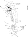
- nucleotomy device 1 making it possible, from holes Pr previously made, following a transosseous approach, in the body of a vertebra Va of a spinal segment Sr of a patient P, the realization in an intervertebral disc Di of a nucleic space Es.
- the nucleotomy apparatus 1 comprises an angular adjustment support 13 fixed on the external part of the body of the patient P and on which is positioned and fixed two cannulas 10 anchored in the body of the corresponding vertebra Va of the spinal segment Sr.
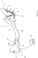
- the two cannulas 10 cooperate respectively with an articulated tube 9 comprising a fixing head 9a allowing, via the link connector 87, the establishment and fixing of a tool holder in the form of a gun 2 comprising connection means 5. and drive means 7 respectively ensuring the positioning and driving in rotation and longitudinal translation of a cutting tool 6.
- the nucleotomy apparatus 1 comprises injection and suction means 8 making it possible to evacuate the debris of the nucleus resulting from the cut during its arrangement inside the intervertebral disc Di.
- the injection and suction means 8 consist of an injection circuit 80 in which circulates physiological serum entering the interior of the nucleic acid space Es being formed and of a suction circuit 81 allowing the recovery of physiological serum and debris produced by the bimetal knife 6a of the cutting tool 6.
- the injection circuit 80 is connected to an injection pump 82 supplied with physiological serum, while the suction circuit 81 is connected to a suction pump 83 comprising a reservoir 84 for the recovery of physiological serum and debris. produced by the bimetal knife 6a of the cutting tool 6.
- the injection and suction means 8 are connected to a control unit 85 controlled by the user by means of control pedals 86.
- the injection and suction means 8 comprise a first and second connecting connector 87 coming to be fixed respectively on the fixing head 9a of the first and second articulated tube 9 introduced inside the first and second cannula 10 previously anchored. in the body of the corresponding Va vertebra of the spinal segment Sr.
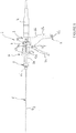
- the connecting connector 87 which consists of a hollow cylindrical sleeve 88 comprising fixing means which consist on the one hand of a cleat 88 a which cooperates with the fixing head 9 a of the corresponding articulated tube 9 and of on the other hand, an articulated clamp 88 b which snaps around the main body 2 a of the tool holder 2.
- the fixing means are also made opposite the cleat 88 has a hinged clamp 88 b comprising two jaws extending from the cylindrical sleeve and in the locking position snaps around the tool holder in the form of spray gun 2.
- the cylindrical sleeve forming the connecting connector 87 comprises a first connection socket 87 a allowing the connection of the injection pipes 80 a , 80 b coming from a Y separation of the injection circuit 80 from the injection means and d suction 8.
- connection connector 87 comprises a second connection socket 87 b allowing either the connection via a connection plug 87 c of the suction circuit 81 of the injection and suction means 8 or the installation by means of a connecting ring 6 e of the cutting tool 6 arranged on the main body 2 a of the tool holder 2.
- connection sockets 87 a , 87 b are positioned on the cylindrical sleeve in diametrically opposite directions so as to open respectively at different levels inside the articulated tube 9 on which and fixed the connection connector 87.
- connection connector 87 arranged on the first articulated tube 9 and whose first connection socket 87 a cooperates, for example, with the pipe 80 a of the injection circuit 80, while the second connection socket 87 b cooperates in a sealed manner with the connection ring 6 e of the cutting tool 6.
- connection socket 87 a opens into a free space 87 d formed between the internal face of the second connection socket 87 b and the external face of the connection ring 6 e of the tool. cut 6.
- the physiological saline from the injection pump 82 is introduced into the connection connector 87 via the pipe 80 a and the first connecting socket 87 a to pass through the free space 87 and to move within the first articulated tube 9 and more particularly between the internal face of a bore 9 b and the external face of a sheath 6 j of the cutting tool 6 to come out inside the nucleic space Es during training.
- connection connector 87 arranged on the second articulated tube 9 and whose first connection socket 87 a cooperates, for example, with the pipe 80 b of the injection circuit 80, while the second connection socket 87 b cooperates in a sealed manner with the connection plug 87 c , the internal bore 87 e of which is connected to the suction circuit 81 of the injection and suction means 8.
- first outlet connection 87a is block by the connection plug 87 c-tight manner to prevent the flow of saline from the injection pump 82, within the second articulated tube 9.
- connection plug 87 c cooperates opposite the suction circuit 81 with the internal bore 9 b of the second tube 9 in order to be able to suck the physiological serum located at inside the Es nucleic space being formed.
- this particular arrangement allows circulation of the physiological serum introduced by the injection pump 82 into the injection circuit 80 a of the first link connector 87 and the recovery, after having crossed the nucleic space Es, of said physiological serum and the debris produced by the bimetal knife of the cutting tool 6 by the suction pump 83 connected to the suction circuit 81 of the second connecting connector 87 ( figure 4 ).
- the physiological serum circulates in a closed loop so as to enter through the first connecting connector 87 arranged on the first articulated tube 9 and carrying the tool holder in the form of a gun 2 to exit via the second connecting connector 87 mounted on the second articulated tube 9 and which has been previously blocked by a plug 87 c .
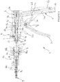
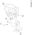
- the gun-shaped tool holder 2 consists of a main body 2 a elongated and hollow inside which are arranged and guided first and second connection means 3 and 5 and the drive means 7 of the tool. cutting 6.
- the main body 2 a of the gun-shaped tool holder 2 is secured perpendicularly to one of its ends with a first fixed handle 2 b inside which is housed adjustment means 11, while a second elastically loaded mobile handle 2 c pivots around the fixed handle 2 b in order to be able to act on the drive means 7 controlling the movements in longitudinal translation and in rotation of the blade cutting tool 6.
- the first connection means 3 housed inside the main body 2 a of the gun-shaped tool holder 2 allow the installation and fixing of an electric motor 4 with rotary drive ensuring the rotation drive by the intermediate of the drive means 7 of the cutting tool 6.
- the first connection means 3 consist of a cylindrical connecting sleeve 3 a fixed inside the main body 2 a of the gun-shaped tool holder 2 and above the fixed handle 2 b .
- the connecting sleeve 3 a makes it possible to snap-fit the electric motor 4 so that its output axis 4 a cooperates with a connecting axis 3 b guided axially inside the main body 2 a of the gun-shaped tool holder 2.
- the connecting pin 3b cooperates with the drive means 7 to ensure the rotational drive of the cutting tool 6.
- the electric motor 4 with rotary drive is connected by means of an electric cord to the control box 85 which is controlled by the user by means of the control pedals 86.
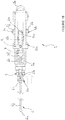
- drive means 7 which consist of a cylindrical connecting sleeve 7 a guided in translation inside the main body 2 a of the gun-shaped tool holder 2.
- connection sleeve 7 a comprises in its internal part a transmission axis 7 b free in rotation and which cooperates with the connection axis 3 b of the first connection means 3
- the connecting sleeve 7 a comprises on its outer periphery and opposite one another guide fingers 7 c , 7 d , respectively passing through an oblong groove 2 g provided in the main body 2 a of the tool holder gun-shaped 2.
- the guide fingers 7 c , 7 d , of the connecting sleeve 7 a open out to the outside of the main body 2 a to be each housed inside an oblong groove 2 h , 2 i made respectively in the branches 2 j and 2 k of a 2 l fork secured to the mobile handle 2 c .
- the connecting sleeve 7 a comprises in the extension of its transmission axis 7 b and opposite the first connection means 3 a transmission bore 7 e allowing the reception of a connecting element 6 b integral with the tool cutting 6 in order to transmit to the latter the rotational movements from the electric motor 4.
- the movable handle 2 c when the movable handle 2 c is activated, the latter allows through its branches 2 j and 2 k extending above the axis of rotation 2 f to move the connecting sleeve 7 a integral with its transmission axis 7 b in translation inside the main body 2 a to simultaneously ensure the translational and rotational movements of the cutting tool 6 fixed to said main body 2 a by means of the second connection means 5 .
- the second connection means 5 and the drive means 7 guided inside the main body 2 a of the gun-shaped tool holder 2 respectively ensure the positioning and the driving in rotation and in longitudinal translation of the cutting tool 6.
- the second connection means 5 are formed at the level of the free end of the main body 2 a of the tool holder in the form of a gun 2 of two diametrically opposed notches 5 a , 5 b intended to receive respectively by snap-fit the locking tabs 6 c , 6 d made in a connection ring 6 e of the cutting tool 6.
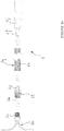
- the cutting tool 6 consists of a flexible metal rod 6 f which is integral at one of its ends by means of a flexible connection 6 g of the bimetal knife 6 a made of deformable material, while the The other end receives after the establishment of the connection ring 6 e the connecting element 6b which is immobilized in translation on said metal rod by a clamping screw 6 h .
- connection ring 6 e cooperates with a clamping mandrel 6 i allowing the establishment and retention of a protective sheath 6 j made of plastic material and enveloping the flexible metal rod 6 f and the flexible connection 6 g carrying the bimetal knife 6 a .
- the flexible connection 6 g making it possible to connect one of the ends of the metal rod to the bimetal knife 6 a is made of a deformable material so that the cutting tool 6 can be deformed and follow small radii of curvature.
- the flexible connection 6 g of the cutting tool 6 consists of a torsion cable 6 k fixed on the one hand to the bimetal knife 6 a and on the other hand to the metal rod 6 f .
- the torsion cable 6 k can be deformed to follow small radii of curvature while ensuring said bimetal knife 6 has a high speed rotational drive.
- the torsion cable 6 k is connected to the bimetal knife 6 a by means of a mechanical link 6 l allowing on the one hand the screwing of said bimetal knife 6 a and on the other hand the fixing by welding of said torsion cable 6 k .
- the mechanical connection 6 l consists of a sleeve comprising at one of its ends a threaded internal bore 6 m intended to cooperate with the threaded part 6n of the bimetal knife 6 a , while the other end of the sleeve is extended by 6 p shoulder of small diameter which is housed inside the 6 k torsion cable to be fixed to the latter by welding.
- the fixing by threaded connection between the internal bore 6 m and the threaded part 6 n of the bimetal knife 6 a is completed by a connection by welding preventing any risk of loosening of the two threaded parts.
- the torsion cable 6 k is attached opposite the bimetal knife 6 a to the metal rod 6 f .
- the metal rod 6 f has a small external diameter so as to be housed inside the torsion cable 6 k and to be fixed to the latter by welding.
- the nucleotomy apparatus 1 comprises adjustment means 11 which consist of a threaded screw 11 a guided in rotation inside the fixed handle 2 b and integral at one of its ends with a wheel 11 b making it possible to position a cursor 11 c at the level of graduations 11 d engraved on either side of an oblong opening 2 d arranged in the upper part of the fixed handle 2 b ( figures 8 and 9 ).
- the screw 11 a cooperates with a lever 2 e connected to a rotation axis 2 f around which the movable handle 2 c pivots.
- the rotational drive of the screw 11 a makes it possible to position the lever 2 e in different angular positions in order to be able to act on the pivoting stroke of the movable handle 2 c and consequently to limit the translational movements of the drive means. 7.
- the nucleotomy apparatus 1 comprises retraction means 12 making it possible to position the bimetal knife 6 a of the cutting tool 6 inside the protective sheath 6 j provided around the metal rod 6 f ( figures 9 and 10 ).
- the retraction means 12 make it possible to act on the flexible metal rod 6 f by pulling on the latter so that the bimetal knife 6 has, due to its super elastic material, deforms and penetrates inside the sheath. protection 6 d .
- the retraction means 12 consist of a trigger 12 a guided in its pivoting on the main body 2 a of the tool holder 2 so as to be able to move a lever 12 b integral with said trigger 12 a and whose free end 12 c is housed inside a bore 2 m formed in said main body 2 a .
- the free end 12 c of the lever 12 b is in permanent contact with the connecting sleeve 7 a drive means 7 to which is connected the cutting tool 6 limiting the rearward stroke of said sleeve, that is, that is to say in the direction of the first connection means of the nucleotomy device 1.
- the surgeon proceeds to the establishment and locking of the two articulated tubes 9 inside the corresponding cannula 10, said cannula being previously fixed and anchored in the body of the vertebra Va of the spinal segment Sr in order to direct said cannulas to the above the intervertebral disc Di in which the nucleic space Es must be arranged.
- first and second articulated tubes 9 It fixes on each of the first and second articulated tubes 9 a first and second connecting connector 87 allowing the installation of the pipes forming the injection 80 and suction circuits 81 respectively connecting the injection pump 82 and the pump of suction 83 of the injection and suction means 8.
- the electric motor 4 and the control pedal 86 are also connected to the control unit 85 of the injection and suction means 8.
- the surgeon chooses from a set of cutting tools a first cutting tool 6 of which the bimetal knife 6 has a cutting diameter of 10 millimeters.
- the tool set comprises two other cutting tools 6 of which the bimetal knife 6 a respectively has a cutting diameter of 14 and 18 millimeters ( figures 17 to 19 ).
- the surgeon presses on the outer ring 7 f of the drive means 7 so as to be able to insert the connecting element 6 b inside the transmission bore 7 e of said drive means.
- the connection ring 6 e of the cutting tool 6 is connected to the second connecting means 5 that comprises the main body 2a of the tool holder 2.
- the locking of the cutting tool 6 on the tool holder 2 is definitively obtained when the surgeon releases the outer ring 7 f from the drive means 7.
- the surgeon must then proceed to protect the bimetal knife 6 a of the cutting tool 6 before its introduction into the first articulated tube 9. To do this, he presses on the trigger 12 has retraction means 12, then he simultaneously pulls on the movable handle 2 c of the tool holder 2 so as to move the metal rod 6 f and the bimetal knife 6 a inside the protective sheath 6 j .
- the trigger 12 a allows by means of its lever 12 b to block the drive means 7 in translation and to keep the bimetal knife 6 a inside said protective sheath 6 j , when the surgeon releases said trigger 12 a and said movable handle 2 c .
- the surgeon adjusts the stroke of the latter as a function of the height of the intervertebral disc Di. To do this, he turns the wheel 11 b by means of adjustment 11 in order to position the cursor 11 c on the graduation 11 d corresponding to the height of said intervertebral disc Di.
- the adjustment means 11 make it possible to act on the angular movement of the movable handle 2 c limiting the latter and therefore the translational movement of the drive means 7.
- surgeon mounts the electric motor 4 on the main body 2 a of the tool holder 2 so that the output shaft 4 a of said motor cooperates with the connecting pin 3 a of the first connection means of said tool holder 2.
- the surgeon introduces the cutting tool 6 assembled to the tool holder 2 inside the first articulated tube 9 previously positioned inside the first cannula 10.
- the cutting tool 6 is completely inserted until the tool holder 2 comes to rest against the connecting connector 87 previously fixed to the first articulated tube 9 by means of the cleat 88 a .
- the surgeon proceeds to fix the tool holder 2 on the connecting connector 87 by closing the jaws of the articulated clamp 88 b so that the latter come to cooperate with a circular peripheral groove 2 n formed in the main body 2 a .
- the surgeon proceeds to produce inside the intervertebral disc Di of the nucleic space Es by the progressive introduction of the bimetal knife 6 a of the tool 6.
- control unit 85 He chooses on the control unit 85 the nucleotomy protocol determining the speed of rotation and the torque of the cutting tool 6 and the starting of the injection 82 and suction pumps 83.
- control pedal 86 to control the electric motor 4 and the rotation of the cutting tool 6.
- the surgeon releases the control pedal 86, retracts the bimetal knife 6 a inside the sheath 6 j , and releases the tool holder 2 from the first connecting connector 87 and extracts said tool holder 2 from the first articulated tube 9.
- the surgeon unscrews the cap 87 c of the second connector 87 arranged on the second articulated tube 9 in order to be able to insert the tool holder 2 provided with its cutting tool 6 of 10 mm diameter inside said tube to come into contact with the intervertebral disc Di.
- the surgeon carries out the same manipulations of the tool holder 2 as those described in the preceding steps above for carrying out the nucleotomy.
- the surgeon releases the control pedal 86, retracts the bimetal knife 6 a inside the sheath 6 j , and releases the tool holder 2 of the second connecting connector 87 and extracts said tool holder 2 from the second articulated tube 9.
- the surgeon takes another tool holder 2 integral with a cutting tool 6 whose cutting diameter is 14 millimeters, introduces it into the second articulated tube 9 to fix it on the second connecting connector 87 to carry out the same operations as described above for the tool holder 2 integral with the cutting tool 6, the cutting diameter of which is 10 millimeters.
- surgeon takes another tool holder 2 integral with a cutting tool 6 whose cutting diameter is 18 millimeters introduced into the first articulated tube 9 to be fixed on the first connecting connector 87 to carry out the same operations as described above for the tool holder 2 integral with the cutting tool 6, the cutting diameter of which is 10 millimeters.
- the surgeon releases the control pedal 86, retracts the bimetal knife 6 a inside the sheath 6 j , and releases the tool holder 2 of the second connecting connector 87 and extracts said tool holder 2 from the second articulated tube 9.
Landscapes
- Health & Medical Sciences (AREA)
- Surgery (AREA)
- Life Sciences & Earth Sciences (AREA)
- Biomedical Technology (AREA)
- Medical Informatics (AREA)
- Orthopedic Medicine & Surgery (AREA)
- Veterinary Medicine (AREA)
- Engineering & Computer Science (AREA)
- Public Health (AREA)
- Heart & Thoracic Surgery (AREA)
- Nuclear Medicine, Radiotherapy & Molecular Imaging (AREA)
- Molecular Biology (AREA)
- Animal Behavior & Ethology (AREA)
- General Health & Medical Sciences (AREA)
- Dentistry (AREA)
- Oral & Maxillofacial Surgery (AREA)
- Surgical Instruments (AREA)
Claims (21)
- Nukleotomie-Vorrichtung, die ausgehend von einem zunächst intraossären Weg, der zuvor in den Körper eines Wirbels Va gebohrt wird, die Erstellung eines Nucleus-Raums Es in einer Bandscheibe Di ermöglicht, die einen Werkzeughalter (2) aufweist, der mit ersten Verbindungsmitteln (3), die das Einsetzen eines Elektromotors (4) mit Drehantrieb ermöglichen, mit zweiten Verbindungsmitteln (5) zum Einsetzen eines Schneidwerkzeugs mit Klinge (6) versehen ist, wobei Antriebsmittel (7) dem Schneidwerkzeug (6) Drehbewegungen und translatorische Längsbewegungen gewährleisten, dadurch gekennzeichnet, dass die Antriebsmittel (7) aus einer zylindrischen Verbindungshülse (7a) gebildet sind, die translatorisch im Inneren des Hauptkörpers (2a) geführt ist und einerseits in ihrem inneren Teil eine frei drehbare Übertragungswelle (7b), die mit der Verbindungswelle (3b) der ersten Verbindungsmittel (3) zusammenwirkt, um das Drehantreiben des Schneidwerkzeugs (6) zu gewährleisten, und andererseits an ihrem Außenumfang und einander gegenüberliegend Führungsstifte (7c, 7d) aufweist, die jeweils eine längliche Nut (2g) durchqueren, die in dem Hauptkörper (2a) des Werkzeughalters (2) ausgebildet ist, um mit den Zinken (2j und 2k) einer Gabel (21) zusammenzuwirken, die mit einem beweglichen Griff (2c) fest verbunden ist, um die translatorischen Bewegungen des Schneidwerkzeugs (6) und der Einspritz- und Ansaugmittel (8) zu gewährleisten, die ermöglichen, die Reste des Nucleus, die beim Schneiden bei ihrem Anordnen im Inneren der Bandscheibe entstanden sind, abzuführen.
- Nukleotomie-Vorrichtung nach Anspruch 1, dadurch gekennzeichnet, dass sie Einstellmittel (11) aufweist, die den Lauf der translatorischen Bewegungen des Schneidwerkzeugs (6) im Inneren der Bandscheibe begrenzen.
- Nukleotomie-Vorrichtung nach Anspruch 1, dadurch gekennzeichnet, dass sie Mittel zum Rückziehen (12) des Schneidwerkzeugs (6) vor seinem Einführen in die Bandscheibe aufweist.
- Nukleotomie-Vorrichtung nach Anspruch 1, dadurch gekennzeichnet, dass das Schneidwerkzeug (6) aus einem flexiblen Metallstab (6f), der von einer Schutzhülle (6j) aus Kunststoff umhüllt ist, aus einer flexiblen Verbindung (6g), die ermöglicht, eines der Enden des Metallstabs (6f) mit einem Zwei-Klingen-Messer (6a), das aus einem superelastischen Material erstellt ist, zu verbinden, aus einem Verbindungselement (6b), das das andere Ende des Metallstabs (6f) mit den Antriebsmitteln (7) des Werkzeughalters (2) verbindet, und einem Verbindungsring (6e) gebildet ist, der mit den zweiten Verbindungsmitteln (5) zum Immobilisieren des Schneidwerkzeugs (6) auf dem Werkzeughalter (2) zusammenwirkt.
- Nukleotomie-Vorrichtung nach Anspruch 4, dadurch gekennzeichnet, dass der Verbindungsring (6e) mit einem Spannfutter (6i) zusammenwirkt, das das Anordnen und das Halten der Schutzhülle (6j) um den flexiblen Metallstab (6f) herum ermöglicht.
- Nukleotomie-Vorrichtung nach Anspruch 4, dadurch gekennzeichnet, dass die flexible Verbindung (6g) des Schneidwerkzeugs (6) aus einem Torsionsdraht (6k) gebildet ist, der einerseits an dem Zwei-Klingen-Messer (6a) und andererseits an dem Metallstab (6f) befestigt ist, wobei sich der Torsionsdraht (6k) verformen kann, um geringen Biegeradien zu folgen und dabei gleichzeitig dem Zwei-Klingen-Messer (6a) einen Drehantrieb mit hoher Drehzahl garantiert.
- Nukleotomie-Vorrichtung nach Anspruch 6, dadurch gekennzeichnet, dass der Torsionsdraht (6k) mit dem Zwei-Klingen-Messer (6a) über eine mechanische Verbindung (6l) verbunden ist, die einerseits das Verschrauben des Zwei-Klingen-Messers (6a) und andererseits das Befestigen an dem Torsionsdraht (6k) durch Schweißen ermöglicht.
- Nukleotomie-Vorrichtung nach Anspruch 7, dadurch gekennzeichnet, dass die mechanische Verbindung (6l) aus einer Hülse gebildet ist, die an einem ihrer Enden eine Gewindeinnenbohrung (6m) aufweist, die dazu bestimmt ist, mit einem Gewindeabschnitt (6n) des Zwei-Klingen-Messers (6a) zusammenzuwirken, während sich das andere Ende der Hülse durch eine Schulter (6p) mit geringem Durchmesser verlängert, die im Inneren des Torsionsdrahts (6k) aufgenommen wird, um an diesem Letzteren durch Schweißen befestigt zu werden.
- Nukleotomie-Vorrichtung nach Anspruch 1, dadurch gekennzeichnet, dass der Werkzeughalter (2) aus einem länglichen und hohlen Hauptkörper (2a) gebildet ist, in dessen Innerem das erste und das zweite Verbindungsmittel (3) und (5) und die Antriebsmittel (7) des Werkzeughalters (2) angeordnet und geführt sind, wobei der Hauptkörper (2a) senkrecht zu einem seiner Enden mit einem ersten festen Griff (2b) fest verbunden ist, in dessen Inneren die Einstellmittel (11) untergebracht sind, während sich ein zweiter beweglicher Griff (2c), der federbelastet ist, um den festen Griff (2b) schwenkbewegt, um auf die Antriebsmittel (7) einzuwirken, die die translatorischen Längsbewegungen und die Drehbewegungen des Schneidwerkzeugs (6) steuern.
- Nukleotomie-Vorrichtung nach Anspruch 1 und 9, dadurch gekennzeichnet, dass die ersten Verbindungsmittel (3) aus einer zylindrischen Verbindungshülse (3a) gebildet sind, die im Inneren des Hauptkörpers (2a) befestigt und geführt ist, wobei die Verbindungshülse (3a) eine Verbindungswelle (3b) aufweist, die einerseits mit einer Ausgangswelle (4a) des Elektromotors (4) und andererseits mit den Antriebsmitteln (7) zusammenwirkt, um den Drehantrieb des Schneidwerkzeugs (6) zu gewährleisten.
- Nukleotomie-Vorrichtung nach Anspruch 1, 4 und 9, dadurch gekennzeichnet, dass die zweiten Verbindungsmittel (5) an dem freien Ende des Hauptkörpers (2a) des Werkzeughalters 2 aus zwei Einkerbungen (5a, 5b) bestehen, die diametral gegenüberliegend sind und dazu bestimmt sind, jeweils durch Einrasten Verriegelungszungen (6c, 6d) aufzunehmen, die in dem Verbindungsring (6e) des Schneidwerkzeugs (6) erstellt sind.
- Nukleotomie-Vorrichtung nach Anspruch 1, dadurch gekennzeichnet, dass die Führungsstifte (7c, 7d) außerhalb des Hauptkörpers (2a) münden, um jeweils innerhalb einer länglichen Nut (2h, 2i) untergebracht zu werden, die jeweils in den Zinken (2j und 2k) der Gabel (21) erstellt ist, die mit dem beweglichen Griff (2c) fest verbunden ist, um die translatorischen Bewegungen des Schneidwerkzeugs (6) zu gewährleisten.
- Nukleotomie-Vorrichtung nach Anspruch 1, dadurch gekennzeichnet, dass die Verbindungshülse (7a) in der Verlängerung ihrer Übertragungswelle (7b) und gegenüberliegend von den ersten Verbindungsmitteln (3) eine Übertragungsbohrung (7e) aufweist, die das Aufnehmen des Verbindungselements (6b) des Schneidwerkzeugs (6) ermöglicht, um auf dieses Letztere die Drehbewegungen zu übertragen, die aus dem Elektromotor (4) hervorgegangen sind.
- Nukleotomie-Vorrichtung nach Anspruch 2, dadurch gekennzeichnet, dass die Einstellmittel (11) aus einer Gewindeschraube (11a) bestehen, die im Inneren des festen Griffs (2b) des Werkzeughalters (2) drehbar geführt ist und an einem ihrer Enden mit einem Rändelrad (11b) fest verbunden ist, das ermöglicht, einen Cursor (11c) an Graduierungen (11d) zu positionieren, die beiderseits einer länglichen Öffnung (2d) eingraviert sind, die in dem oberen Teil des festen Griffs (2b) ausgebildet sind, wobei die Schraube (11a) mit einem Hebel (2e) zusammenwirkt, der mit einer Drehwelle (2f) verbunden ist, um die sich der bewegliche Griff (2c) derart schwenkbewegt, dass das Indrehungversetzen der Schraube (11a) ermöglicht, den Hebel (2e) in verschiedenen Winkelpositionen zu positionieren, um auf den Schwenkweg des beweglichen Griffs (2c) einzuwirken und folglich die translatorischen Bewegungen der Antriebsmittel (7) zu begrenzen.
- Nukleotomie-Vorrichtung nach Anspruch 3, dadurch gekennzeichnet, dass die Mittel zum Rückziehen (12) aus einem Auslöser (12a) gebildet sind, der in seinen Schwenkbewegungen auf dem Hauptkörper (2a) des Werkzeughalters (2) derart geführt ist, um einen Hebel (12b) zu bewegen, der mit dem Auslöser (12a) fest verbunden ist und dessen freies Ende (12c) im Inneren einer Bohrung (2m) untergebracht ist, die in dem Hauptkörper (2a) ausgebildet ist.
- Nukleotomie-Vorrichtung nach Anspruch 1, dadurch gekennzeichnet, dass die Einspritz- und Ansaugmittel (8) aus einem Einspritzkreis (80), in dem physiologische Kochsalzlösung fließt, die ins Innere des sich in Bildung befindlichen Nucleus-Raums Es eindringt, und einem Ansaugkreis (81) gebildet sind, der das Rückgewinnen der physiologischen Kochsalzlösung und der Reste, die durch das Zwei-Klingen-Messer (6a) des Schneidwerkzeugs (6) erzeugt werden, ermöglicht.
- Nukleotomie-Vorrichtung nach Anspruch 16, dadurch gekennzeichnet, dass der Einspritzkreis (80) an eine Einspritzpumpe (82) angeschlossen ist, die mit physiologischer Kochsalzlösung gespeist wird, während der Ansaugkreis (81) mit einer Ansaugpumpe (83) verbunden ist, die einen Behälter (84) für das Rückgewinnen der physiologischen Kochsalzlösung und der Reste aufweist.
- Nukleotomie-Vorrichtung nach Anspruch 1, dadurch gekennzeichnet, dass der Elektromotor (4) mit Drehantrieb und die Einspritz- und Ansaugmittel (8) mit einem Steuerkasten (85) verbunden sind, der von dem Benutzer mit Hilfe von Steuerungspedalen (86) gesteuert wird.
- Nukleotomie-Vorrichtung nach Anspruch 1, dadurch gekennzeichnet, dass die Einspritz- und Ansaugmittel (8) aus einem Verbindungsstecker (87) gebildet sind, der einerseits an dem Ende eines Gelenkrohrs (9), das zuvor in den Körper des entsprechenden Wirbels Va implantiert worden ist, und andererseits an dem Hauptkörper (2a) des Werkzeughalters (2) befestigt wird.
- Nukleotomie-Vorrichtung nach Anspruch 19, dadurch gekennzeichnet, dass der Verbindungsstecker (87) Befestigungsmittel (88) aufweist, die einerseits aus einer Nase (88a), die mit dem Befestigungskopf (9a) des Gelenkrohrs (9) zusammenwirkt, und andererseits aus einer Gelenkzange (88b) gebildet sind, die um den Hauptkörper (2a) des Werkzeughalters (2) einrastet.
- Nukleotomie-Vorrichtung nach Anspruch 19, dadurch gekennzeichnet, dass der Verbindungsstecker (87) Anschlussdosen (87a und 87b) zum Befestigen des Einspritz- (80) und des Ansaugkreises (81) aufweist.
Applications Claiming Priority (2)
| Application Number | Priority Date | Filing Date | Title |
|---|---|---|---|
| FR1256963A FR2993448B1 (fr) | 2012-07-19 | 2012-07-19 | Ensemble d'entrainement pour outil de coupe dans un dispositif de nucleotomie |
| PCT/FR2013/051631 WO2014013162A1 (fr) | 2012-07-19 | 2013-07-09 | Ensemble d'entraînement pour outil de coupe de type shaver |
Publications (2)
| Publication Number | Publication Date |
|---|---|
| EP2874573A1 EP2874573A1 (de) | 2015-05-27 |
| EP2874573B1 true EP2874573B1 (de) | 2020-09-02 |
Family
ID=47003043
Family Applications (1)
| Application Number | Title | Priority Date | Filing Date |
|---|---|---|---|
| EP13747437.5A Not-in-force EP2874573B1 (de) | 2012-07-19 | 2013-07-09 | Antriebsanordnung für eine schneideeinheit eines rasierapparats |
Country Status (8)
| Country | Link |
|---|---|
| EP (1) | EP2874573B1 (de) |
| JP (1) | JP6116686B2 (de) |
| KR (1) | KR20150037871A (de) |
| CN (1) | CN104507421B (de) |
| AU (1) | AU2013291846B2 (de) |
| BR (1) | BR112015001143A2 (de) |
| FR (1) | FR2993448B1 (de) |
| WO (1) | WO2014013162A1 (de) |
Families Citing this family (2)
| Publication number | Priority date | Publication date | Assignee | Title |
|---|---|---|---|---|
| JP3064486B2 (ja) | 1991-06-04 | 2000-07-12 | 株式会社東芝 | 駆動力伝達装置及びその製造方法並びに駆動力伝達装置を備えた伸展構造物 |
| CN121081074B (zh) * | 2025-09-30 | 2026-05-01 | 广州佳林医疗用品制造有限公司 | 一种组织切割工具 |
Citations (1)
| Publication number | Priority date | Publication date | Assignee | Title |
|---|---|---|---|---|
| US20100152758A1 (en) * | 2008-12-16 | 2010-06-17 | Mark Joseph L | Tissue removal device for neurosurgical and spinal surgery applications |
Family Cites Families (11)
| Publication number | Priority date | Publication date | Assignee | Title |
|---|---|---|---|---|
| FR1100199A (fr) | 1954-05-24 | 1955-09-16 | Microcell Ltd | Perfectionnements aux matières plastiques et applications de ces perfectionnements |
| CN2298780Y (zh) * | 1997-02-21 | 1998-12-02 | 张大勇 | 髓核环切器 |
| US6958071B2 (en) * | 2002-07-13 | 2005-10-25 | Stryker Corporation | Surgical tool system |
| AU2003230740B2 (en) * | 2002-11-08 | 2008-10-09 | Warsaw Orthopedic, Inc. | Transpedicular intervertebral disk access methods and devices |
| US8277474B2 (en) * | 2004-05-26 | 2012-10-02 | Medtronic, Inc. | Surgical cutting instrument |
| WO2007008703A2 (en) * | 2005-07-08 | 2007-01-18 | Conceptual Gray, Llc | Apparatus and method thereof for drilling holes in discrete controlled increments |
| CN200973739Y (zh) * | 2006-04-26 | 2007-11-14 | 谭锐 | 椎间盘纤维环套筒切开刀 |
| US20100152762A1 (en) * | 2008-12-16 | 2010-06-17 | Mark Joseph L | Tissue removal system with multi-directional foot actuator assembly for neurosurgical and spinal surgery applications |
| US8403916B2 (en) * | 2009-02-26 | 2013-03-26 | Enteroptyx | Surgical instrument having a magnetically driven detachable tool assembly |
| US8142463B2 (en) * | 2009-03-13 | 2012-03-27 | Kyphon Sarl | Battery operated nucleus disruptor device for intervertebral disc |
| US9168047B2 (en) * | 2009-04-02 | 2015-10-27 | John T. To | Minimally invasive discectomy |
-
2012
- 2012-07-19 FR FR1256963A patent/FR2993448B1/fr not_active Expired - Fee Related
-
2013
- 2013-07-09 BR BR112015001143A patent/BR112015001143A2/pt not_active Application Discontinuation
- 2013-07-09 JP JP2015522143A patent/JP6116686B2/ja active Active
- 2013-07-09 WO PCT/FR2013/051631 patent/WO2014013162A1/fr not_active Ceased
- 2013-07-09 EP EP13747437.5A patent/EP2874573B1/de not_active Not-in-force
- 2013-07-09 AU AU2013291846A patent/AU2013291846B2/en not_active Ceased
- 2013-07-09 KR KR20157001749A patent/KR20150037871A/ko not_active Withdrawn
- 2013-07-09 CN CN201380038475.3A patent/CN104507421B/zh not_active Expired - Fee Related
Patent Citations (1)
| Publication number | Priority date | Publication date | Assignee | Title |
|---|---|---|---|---|
| US20100152758A1 (en) * | 2008-12-16 | 2010-06-17 | Mark Joseph L | Tissue removal device for neurosurgical and spinal surgery applications |
Also Published As
| Publication number | Publication date |
|---|---|
| CN104507421B (zh) | 2016-12-28 |
| JP6116686B2 (ja) | 2017-04-19 |
| CN104507421A (zh) | 2015-04-08 |
| BR112015001143A2 (pt) | 2017-06-27 |
| KR20150037871A (ko) | 2015-04-08 |
| FR2993448A1 (fr) | 2014-01-24 |
| EP2874573A1 (de) | 2015-05-27 |
| AU2013291846A1 (en) | 2015-03-05 |
| WO2014013162A1 (fr) | 2014-01-23 |
| AU2013291846B2 (en) | 2017-12-07 |
| FR2993448B1 (fr) | 2014-07-25 |
| JP2015523159A (ja) | 2015-08-13 |
Similar Documents
| Publication | Publication Date | Title |
|---|---|---|
| EP1027902B1 (de) | Injektionsspritze mit Selbstschutz | |
| EP2705866B1 (de) | Vorrichtung zur Schmerzreduzierung bei der Einführung einer Spritzennadel in die Haut | |
| EP2296733B1 (de) | Vorrichtung zur injektion einer medizinischen flüssigkeit zur medizinischen verwendung | |
| US20140025079A1 (en) | Driving assembly for a cutting tool of the shaver type | |
| WO2012101354A1 (fr) | Dispositif de forage pour la réalisation d'un canal osseux à profil courbe à l'intérieur du corps d'une vertèbre | |
| EP1357845A1 (de) | Endoskopische schneidezange | |
| FR2522508A1 (fr) | Ensemble pour l'introduction de catheters | |
| EP1118401B1 (de) | Aufweitungsvorrichtung zum Formen von Muffen an Rohrenden | |
| WO2009080996A2 (fr) | Appareillage medical avec systeme de connexion et de deconnexion pour un instrument medical separable | |
| WO2017046531A1 (fr) | Dispositif pour le couplage stérile d'un instrument chirurgical percutané et d'un outil d'entrainement et méthode pour réaliser un tel couplage | |
| EP1274350B1 (de) | Applikator zum einbringen einer chirurgischen nadel | |
| FR2993448A1 (fr) | Ensemble d'entrainement pour outil de coupe dans un dispositif de nucleotomie | |
| FR2810555A1 (fr) | Catheter reutilisable | |
| EP2705873B1 (de) | Entfernbares Blockiersystem eines Katheters | |
| EP3709920B1 (de) | Anordnung und vorrichtung zur endovenösen behandlung | |
| FR3107445A1 (fr) | Coupleur et dispositif chirurgical à collerette de recouvrement d’une enveloppe souple stérile | |
| FR2837735A1 (fr) | Porte-outil pour outil deformable en flexion | |
| EP1014129B1 (de) | Stecker für optische Faser mit einer Aussparung zum Einspritzen von Klebstoff | |
| FR2860136A1 (fr) | Instrument de travail destine a etre utilise avec un resectoscope et muni d'un corps formant poignee, et corps formant poignee pour un instrument de travail | |
| EP1180052A1 (de) | Kartusche zum aufbewahren und auftragen einer flüssigkeit auf die haut | |
| EP3639884B1 (de) | Kupplungssystem zwischen einem leadless herzimplantat und einem zugehörigen implantationswerkzeug | |
| WO2026062540A1 (fr) | Instrument et installation robotisée de chirurgie otologique pour l'insertion intra cochléaire d'une électrode d'implant cochléaire | |
| EP0787467A1 (de) | Schutzvorrichtung für Knochennagel | |
| FR3166294A1 (fr) | Instrument, installation robotisée de chirurgie otologique et procédé pour l’insertion intra cochléaire d’une électrode d’implant cochléaire | |
| FR2821265A1 (fr) | Dispositif de protection de broches chirurgicales |
Legal Events
| Date | Code | Title | Description |
|---|---|---|---|
| PUAI | Public reference made under article 153(3) epc to a published international application that has entered the european phase |
Free format text: ORIGINAL CODE: 0009012 |
|
| 17P | Request for examination filed |
Effective date: 20150219 |
|
| AK | Designated contracting states |
Kind code of ref document: A1 Designated state(s): AL AT BE BG CH CY CZ DE DK EE ES FI FR GB GR HR HU IE IS IT LI LT LU LV MC MK MT NL NO PL PT RO RS SE SI SK SM TR |
|
| AX | Request for extension of the european patent |
Extension state: BA ME |
|
| RAP1 | Party data changed (applicant data changed or rights of an application transferred) |
Owner name: CLARIANCE |
|
| DAX | Request for extension of the european patent (deleted) | ||
| STAA | Information on the status of an ep patent application or granted ep patent |
Free format text: STATUS: EXAMINATION IS IN PROGRESS |
|
| 17Q | First examination report despatched |
Effective date: 20190723 |
|
| GRAP | Despatch of communication of intention to grant a patent |
Free format text: ORIGINAL CODE: EPIDOSNIGR1 |
|
| STAA | Information on the status of an ep patent application or granted ep patent |
Free format text: STATUS: GRANT OF PATENT IS INTENDED |
|
| INTG | Intention to grant announced |
Effective date: 20200403 |
|
| GRAS | Grant fee paid |
Free format text: ORIGINAL CODE: EPIDOSNIGR3 |
|
| GRAA | (expected) grant |
Free format text: ORIGINAL CODE: 0009210 |
|
| STAA | Information on the status of an ep patent application or granted ep patent |
Free format text: STATUS: THE PATENT HAS BEEN GRANTED |
|
| AK | Designated contracting states |
Kind code of ref document: B1 Designated state(s): AL AT BE BG CH CY CZ DE DK EE ES FI FR GB GR HR HU IE IS IT LI LT LU LV MC MK MT NL NO PL PT RO RS SE SI SK SM TR |
|
| REG | Reference to a national code |
Ref country code: GB Ref legal event code: FG4D Free format text: NOT ENGLISH |
|
| REG | Reference to a national code |
Ref country code: AT Ref legal event code: REF Ref document number: 1307932 Country of ref document: AT Kind code of ref document: T Effective date: 20200915 Ref country code: CH Ref legal event code: EP |
|
| REG | Reference to a national code |
Ref country code: DE Ref legal event code: R096 Ref document number: 602013072155 Country of ref document: DE |
|
| REG | Reference to a national code |
Ref country code: IE Ref legal event code: FG4D Free format text: LANGUAGE OF EP DOCUMENT: FRENCH |
|
| REG | Reference to a national code |
Ref country code: LT Ref legal event code: MG4D |
|
| PG25 | Lapsed in a contracting state [announced via postgrant information from national office to epo] |
Ref country code: BG Free format text: LAPSE BECAUSE OF FAILURE TO SUBMIT A TRANSLATION OF THE DESCRIPTION OR TO PAY THE FEE WITHIN THE PRESCRIBED TIME-LIMIT Effective date: 20201202 Ref country code: LT Free format text: LAPSE BECAUSE OF FAILURE TO SUBMIT A TRANSLATION OF THE DESCRIPTION OR TO PAY THE FEE WITHIN THE PRESCRIBED TIME-LIMIT Effective date: 20200902 Ref country code: FI Free format text: LAPSE BECAUSE OF FAILURE TO SUBMIT A TRANSLATION OF THE DESCRIPTION OR TO PAY THE FEE WITHIN THE PRESCRIBED TIME-LIMIT Effective date: 20200902 Ref country code: SE Free format text: LAPSE BECAUSE OF FAILURE TO SUBMIT A TRANSLATION OF THE DESCRIPTION OR TO PAY THE FEE WITHIN THE PRESCRIBED TIME-LIMIT Effective date: 20200902 Ref country code: HR Free format text: LAPSE BECAUSE OF FAILURE TO SUBMIT A TRANSLATION OF THE DESCRIPTION OR TO PAY THE FEE WITHIN THE PRESCRIBED TIME-LIMIT Effective date: 20200902 Ref country code: NO Free format text: LAPSE BECAUSE OF FAILURE TO SUBMIT A TRANSLATION OF THE DESCRIPTION OR TO PAY THE FEE WITHIN THE PRESCRIBED TIME-LIMIT Effective date: 20201202 Ref country code: GR Free format text: LAPSE BECAUSE OF FAILURE TO SUBMIT A TRANSLATION OF THE DESCRIPTION OR TO PAY THE FEE WITHIN THE PRESCRIBED TIME-LIMIT Effective date: 20201203 |
|
| REG | Reference to a national code |
Ref country code: NL Ref legal event code: MP Effective date: 20200902 |
|
| REG | Reference to a national code |
Ref country code: AT Ref legal event code: MK05 Ref document number: 1307932 Country of ref document: AT Kind code of ref document: T Effective date: 20200902 |
|
| PG25 | Lapsed in a contracting state [announced via postgrant information from national office to epo] |
Ref country code: LV Free format text: LAPSE BECAUSE OF FAILURE TO SUBMIT A TRANSLATION OF THE DESCRIPTION OR TO PAY THE FEE WITHIN THE PRESCRIBED TIME-LIMIT Effective date: 20200902 Ref country code: PL Free format text: LAPSE BECAUSE OF FAILURE TO SUBMIT A TRANSLATION OF THE DESCRIPTION OR TO PAY THE FEE WITHIN THE PRESCRIBED TIME-LIMIT Effective date: 20200902 Ref country code: RS Free format text: LAPSE BECAUSE OF FAILURE TO SUBMIT A TRANSLATION OF THE DESCRIPTION OR TO PAY THE FEE WITHIN THE PRESCRIBED TIME-LIMIT Effective date: 20200902 |
|
| PG25 | Lapsed in a contracting state [announced via postgrant information from national office to epo] |
Ref country code: EE Free format text: LAPSE BECAUSE OF FAILURE TO SUBMIT A TRANSLATION OF THE DESCRIPTION OR TO PAY THE FEE WITHIN THE PRESCRIBED TIME-LIMIT Effective date: 20200902 Ref country code: CZ Free format text: LAPSE BECAUSE OF FAILURE TO SUBMIT A TRANSLATION OF THE DESCRIPTION OR TO PAY THE FEE WITHIN THE PRESCRIBED TIME-LIMIT Effective date: 20200902 Ref country code: SM Free format text: LAPSE BECAUSE OF FAILURE TO SUBMIT A TRANSLATION OF THE DESCRIPTION OR TO PAY THE FEE WITHIN THE PRESCRIBED TIME-LIMIT Effective date: 20200902 Ref country code: RO Free format text: LAPSE BECAUSE OF FAILURE TO SUBMIT A TRANSLATION OF THE DESCRIPTION OR TO PAY THE FEE WITHIN THE PRESCRIBED TIME-LIMIT Effective date: 20200902 Ref country code: PT Free format text: LAPSE BECAUSE OF FAILURE TO SUBMIT A TRANSLATION OF THE DESCRIPTION OR TO PAY THE FEE WITHIN THE PRESCRIBED TIME-LIMIT Effective date: 20210104 Ref country code: NL Free format text: LAPSE BECAUSE OF FAILURE TO SUBMIT A TRANSLATION OF THE DESCRIPTION OR TO PAY THE FEE WITHIN THE PRESCRIBED TIME-LIMIT Effective date: 20200902 |
|
| PG25 | Lapsed in a contracting state [announced via postgrant information from national office to epo] |
Ref country code: IS Free format text: LAPSE BECAUSE OF FAILURE TO SUBMIT A TRANSLATION OF THE DESCRIPTION OR TO PAY THE FEE WITHIN THE PRESCRIBED TIME-LIMIT Effective date: 20210102 Ref country code: ES Free format text: LAPSE BECAUSE OF FAILURE TO SUBMIT A TRANSLATION OF THE DESCRIPTION OR TO PAY THE FEE WITHIN THE PRESCRIBED TIME-LIMIT Effective date: 20200902 Ref country code: AT Free format text: LAPSE BECAUSE OF FAILURE TO SUBMIT A TRANSLATION OF THE DESCRIPTION OR TO PAY THE FEE WITHIN THE PRESCRIBED TIME-LIMIT Effective date: 20200902 Ref country code: AL Free format text: LAPSE BECAUSE OF FAILURE TO SUBMIT A TRANSLATION OF THE DESCRIPTION OR TO PAY THE FEE WITHIN THE PRESCRIBED TIME-LIMIT Effective date: 20200902 |
|
| REG | Reference to a national code |
Ref country code: DE Ref legal event code: R097 Ref document number: 602013072155 Country of ref document: DE |
|
| PG25 | Lapsed in a contracting state [announced via postgrant information from national office to epo] |
Ref country code: SK Free format text: LAPSE BECAUSE OF FAILURE TO SUBMIT A TRANSLATION OF THE DESCRIPTION OR TO PAY THE FEE WITHIN THE PRESCRIBED TIME-LIMIT Effective date: 20200902 |
|
| PLBE | No opposition filed within time limit |
Free format text: ORIGINAL CODE: 0009261 |
|
| STAA | Information on the status of an ep patent application or granted ep patent |
Free format text: STATUS: NO OPPOSITION FILED WITHIN TIME LIMIT |
|
| 26N | No opposition filed |
Effective date: 20210603 |
|
| PG25 | Lapsed in a contracting state [announced via postgrant information from national office to epo] |
Ref country code: SI Free format text: LAPSE BECAUSE OF FAILURE TO SUBMIT A TRANSLATION OF THE DESCRIPTION OR TO PAY THE FEE WITHIN THE PRESCRIBED TIME-LIMIT Effective date: 20200902 Ref country code: DK Free format text: LAPSE BECAUSE OF FAILURE TO SUBMIT A TRANSLATION OF THE DESCRIPTION OR TO PAY THE FEE WITHIN THE PRESCRIBED TIME-LIMIT Effective date: 20200902 |
|
| PG25 | Lapsed in a contracting state [announced via postgrant information from national office to epo] |
Ref country code: IT Free format text: LAPSE BECAUSE OF FAILURE TO SUBMIT A TRANSLATION OF THE DESCRIPTION OR TO PAY THE FEE WITHIN THE PRESCRIBED TIME-LIMIT Effective date: 20200902 |
|
| REG | Reference to a national code |
Ref country code: DE Ref legal event code: R119 Ref document number: 602013072155 Country of ref document: DE |
|
| REG | Reference to a national code |
Ref country code: CH Ref legal event code: PL |
|
| GBPC | Gb: european patent ceased through non-payment of renewal fee |
Effective date: 20210709 |
|
| PG25 | Lapsed in a contracting state [announced via postgrant information from national office to epo] |
Ref country code: MC Free format text: LAPSE BECAUSE OF FAILURE TO SUBMIT A TRANSLATION OF THE DESCRIPTION OR TO PAY THE FEE WITHIN THE PRESCRIBED TIME-LIMIT Effective date: 20200902 |
|
| REG | Reference to a national code |
Ref country code: BE Ref legal event code: MM Effective date: 20210731 |
|
| PG25 | Lapsed in a contracting state [announced via postgrant information from national office to epo] |
Ref country code: LI Free format text: LAPSE BECAUSE OF NON-PAYMENT OF DUE FEES Effective date: 20210731 Ref country code: GB Free format text: LAPSE BECAUSE OF NON-PAYMENT OF DUE FEES Effective date: 20210709 Ref country code: DE Free format text: LAPSE BECAUSE OF NON-PAYMENT OF DUE FEES Effective date: 20220201 Ref country code: CH Free format text: LAPSE BECAUSE OF NON-PAYMENT OF DUE FEES Effective date: 20210731 |
|
| PG25 | Lapsed in a contracting state [announced via postgrant information from national office to epo] |
Ref country code: LU Free format text: LAPSE BECAUSE OF NON-PAYMENT OF DUE FEES Effective date: 20210709 |
|
| PG25 | Lapsed in a contracting state [announced via postgrant information from national office to epo] |
Ref country code: IE Free format text: LAPSE BECAUSE OF NON-PAYMENT OF DUE FEES Effective date: 20210709 Ref country code: BE Free format text: LAPSE BECAUSE OF NON-PAYMENT OF DUE FEES Effective date: 20210731 |
|
| PG25 | Lapsed in a contracting state [announced via postgrant information from national office to epo] |
Ref country code: HU Free format text: LAPSE BECAUSE OF FAILURE TO SUBMIT A TRANSLATION OF THE DESCRIPTION OR TO PAY THE FEE WITHIN THE PRESCRIBED TIME-LIMIT; INVALID AB INITIO Effective date: 20130709 |
|
| PG25 | Lapsed in a contracting state [announced via postgrant information from national office to epo] |
Ref country code: CY Free format text: LAPSE BECAUSE OF FAILURE TO SUBMIT A TRANSLATION OF THE DESCRIPTION OR TO PAY THE FEE WITHIN THE PRESCRIBED TIME-LIMIT Effective date: 20200902 |
|
| PG25 | Lapsed in a contracting state [announced via postgrant information from national office to epo] |
Ref country code: MK Free format text: LAPSE BECAUSE OF FAILURE TO SUBMIT A TRANSLATION OF THE DESCRIPTION OR TO PAY THE FEE WITHIN THE PRESCRIBED TIME-LIMIT Effective date: 20200902 |
|
| PG25 | Lapsed in a contracting state [announced via postgrant information from national office to epo] |
Ref country code: TR Free format text: LAPSE BECAUSE OF FAILURE TO SUBMIT A TRANSLATION OF THE DESCRIPTION OR TO PAY THE FEE WITHIN THE PRESCRIBED TIME-LIMIT Effective date: 20200902 |
|
| PG25 | Lapsed in a contracting state [announced via postgrant information from national office to epo] |
Ref country code: MT Free format text: LAPSE BECAUSE OF FAILURE TO SUBMIT A TRANSLATION OF THE DESCRIPTION OR TO PAY THE FEE WITHIN THE PRESCRIBED TIME-LIMIT Effective date: 20200902 |
|
| PGFP | Annual fee paid to national office [announced via postgrant information from national office to epo] |
Ref country code: FR Payment date: 20240729 Year of fee payment: 12 |
|
| PG25 | Lapsed in a contracting state [announced via postgrant information from national office to epo] |
Ref country code: FR Free format text: LAPSE BECAUSE OF NON-PAYMENT OF DUE FEES Effective date: 20250731 |