EP3407734B1 - Biosecurity system for an agricultural dwelling - Google Patents
Biosecurity system for an agricultural dwelling Download PDFInfo
- Publication number
- EP3407734B1 EP3407734B1 EP17744763.8A EP17744763A EP3407734B1 EP 3407734 B1 EP3407734 B1 EP 3407734B1 EP 17744763 A EP17744763 A EP 17744763A EP 3407734 B1 EP3407734 B1 EP 3407734B1
- Authority
- EP
- European Patent Office
- Prior art keywords
- light
- room
- lighting
- chamber
- wavelengths
- Prior art date
- Legal status (The legal status is an assumption and is not a legal conclusion. Google has not performed a legal analysis and makes no representation as to the accuracy of the status listed.)
- Active
Links
- CBENFWSGALASAD-UHFFFAOYSA-N Ozone Chemical compound [O-][O+]=O CBENFWSGALASAD-UHFFFAOYSA-N 0.000 claims description 26
- 238000000034 method Methods 0.000 claims description 24
- 241000894006 Bacteria Species 0.000 claims description 17
- 241000700605 Viruses Species 0.000 claims description 15
- 230000003595 spectral effect Effects 0.000 claims description 10
- 241000282412 Homo Species 0.000 claims description 8
- 230000007613 environmental effect Effects 0.000 claims description 7
- 238000011012 sanitization Methods 0.000 claims description 7
- 238000012544 monitoring process Methods 0.000 claims description 5
- 244000144972 livestock Species 0.000 claims description 4
- 238000007599 discharging Methods 0.000 claims description 2
- 239000000126 substance Substances 0.000 claims description 2
- XLYOFNOQVPJJNP-UHFFFAOYSA-N water Substances O XLYOFNOQVPJJNP-UHFFFAOYSA-N 0.000 description 7
- 101000613615 Homo sapiens Protein mono-ADP-ribosyltransferase PARP14 Proteins 0.000 description 5
- 102100040848 Protein mono-ADP-ribosyltransferase PARP14 Human genes 0.000 description 5
- 241000282898 Sus scrofa Species 0.000 description 5
- 239000011159 matrix material Substances 0.000 description 5
- 230000005855 radiation Effects 0.000 description 5
- 108020004414 DNA Proteins 0.000 description 4
- 238000010586 diagram Methods 0.000 description 4
- 201000010099 disease Diseases 0.000 description 4
- 208000037265 diseases, disorders, signs and symptoms Diseases 0.000 description 4
- 239000000463 material Substances 0.000 description 4
- 230000015654 memory Effects 0.000 description 3
- 244000005700 microbiome Species 0.000 description 3
- 244000144977 poultry Species 0.000 description 3
- 235000013594 poultry meat Nutrition 0.000 description 3
- 101000751000 Bacillus subtilis (strain 168) 50S ribosomal protein L1 Proteins 0.000 description 2
- 101000718962 Bacillus subtilis (strain 168) 50S ribosomal protein L2 Proteins 0.000 description 2
- 101000935024 Bungarus multicinctus Beta-bungarotoxin B chain-like Proteins 0.000 description 2
- 102100024649 Cell adhesion molecule 1 Human genes 0.000 description 2
- 101000760620 Homo sapiens Cell adhesion molecule 1 Proteins 0.000 description 2
- 101000735459 Homo sapiens Protein mono-ADP-ribosyltransferase PARP9 Proteins 0.000 description 2
- 102100034930 Protein mono-ADP-ribosyltransferase PARP9 Human genes 0.000 description 2
- QVGXLLKOCUKJST-UHFFFAOYSA-N atomic oxygen Chemical compound [O] QVGXLLKOCUKJST-UHFFFAOYSA-N 0.000 description 2
- 230000008901 benefit Effects 0.000 description 2
- 238000004891 communication Methods 0.000 description 2
- 239000000356 contaminant Substances 0.000 description 2
- 239000000203 mixture Substances 0.000 description 2
- 229910052760 oxygen Inorganic materials 0.000 description 2
- 239000001301 oxygen Substances 0.000 description 2
- 241000283690 Bos taurus Species 0.000 description 1
- OKTJSMMVPCPJKN-UHFFFAOYSA-N Carbon Chemical compound [C] OKTJSMMVPCPJKN-UHFFFAOYSA-N 0.000 description 1
- 206010012735 Diarrhoea Diseases 0.000 description 1
- 241000283086 Equidae Species 0.000 description 1
- 241000287828 Gallus gallus Species 0.000 description 1
- 208000002979 Influenza in Birds Diseases 0.000 description 1
- 241001465754 Metazoa Species 0.000 description 1
- 241000286209 Phasianidae Species 0.000 description 1
- 241001135549 Porcine epidemic diarrhea virus Species 0.000 description 1
- 108091093078 Pyrimidine dimer Proteins 0.000 description 1
- 206010064097 avian influenza Diseases 0.000 description 1
- 244000052616 bacterial pathogen Species 0.000 description 1
- 235000013361 beverage Nutrition 0.000 description 1
- 229910052799 carbon Inorganic materials 0.000 description 1
- 239000003610 charcoal Substances 0.000 description 1
- 235000013330 chicken meat Nutrition 0.000 description 1
- 238000004590 computer program Methods 0.000 description 1
- 238000005202 decontamination Methods 0.000 description 1
- 230000003588 decontaminative effect Effects 0.000 description 1
- 230000001419 dependent effect Effects 0.000 description 1
- 230000000694 effects Effects 0.000 description 1
- 238000009429 electrical wiring Methods 0.000 description 1
- 244000144992 flock Species 0.000 description 1
- 235000013305 food Nutrition 0.000 description 1
- 238000009472 formulation Methods 0.000 description 1
- 230000006870 function Effects 0.000 description 1
- 230000000415 inactivating effect Effects 0.000 description 1
- 150000002500 ions Chemical class 0.000 description 1
- 230000007257 malfunction Effects 0.000 description 1
- 238000004519 manufacturing process Methods 0.000 description 1
- 230000007935 neutral effect Effects 0.000 description 1
- 230000003287 optical effect Effects 0.000 description 1
- 230000008092 positive effect Effects 0.000 description 1
- 230000003362 replicative effect Effects 0.000 description 1
- 230000001954 sterilising effect Effects 0.000 description 1
- 238000004659 sterilization and disinfection Methods 0.000 description 1
- RWQNBRDOKXIBIV-UHFFFAOYSA-N thymine Chemical class CC1=CNC(=O)NC1=O RWQNBRDOKXIBIV-UHFFFAOYSA-N 0.000 description 1
Images


Classifications
-
- A—HUMAN NECESSITIES
- A23—FOODS OR FOODSTUFFS; TREATMENT THEREOF, NOT COVERED BY OTHER CLASSES
- A23L—FOODS, FOODSTUFFS, OR NON-ALCOHOLIC BEVERAGES, NOT COVERED BY SUBCLASSES A21D OR A23B-A23J; THEIR PREPARATION OR TREATMENT, e.g. COOKING, MODIFICATION OF NUTRITIVE QUALITIES, PHYSICAL TREATMENT; PRESERVATION OF FOODS OR FOODSTUFFS, IN GENERAL
- A23L3/00—Preservation of foods or foodstuffs, in general, e.g. pasteurising, sterilising, specially adapted for foods or foodstuffs
- A23L3/34—Preservation of foods or foodstuffs, in general, e.g. pasteurising, sterilising, specially adapted for foods or foodstuffs by treatment with chemicals
- A23L3/3409—Preservation of foods or foodstuffs, in general, e.g. pasteurising, sterilising, specially adapted for foods or foodstuffs by treatment with chemicals in the form of gases, e.g. fumigation; Compositions or apparatus therefor
- A23L3/3418—Preservation of foods or foodstuffs, in general, e.g. pasteurising, sterilising, specially adapted for foods or foodstuffs by treatment with chemicals in the form of gases, e.g. fumigation; Compositions or apparatus therefor in a controlled atmosphere, e.g. partial vacuum, comprising only CO2, N2, O2 or H2O
-
- A—HUMAN NECESSITIES
- A61—MEDICAL OR VETERINARY SCIENCE; HYGIENE
- A61L—METHODS OR APPARATUS FOR STERILISING MATERIALS OR OBJECTS IN GENERAL; DISINFECTION, STERILISATION OR DEODORISATION OF AIR; CHEMICAL ASPECTS OF BANDAGES, DRESSINGS, ABSORBENT PADS OR SURGICAL ARTICLES; MATERIALS FOR BANDAGES, DRESSINGS, ABSORBENT PADS OR SURGICAL ARTICLES
- A61L2/00—Methods or apparatus for disinfecting or sterilising materials or objects other than foodstuffs or contact lenses; Accessories therefor
- A61L2/02—Methods or apparatus for disinfecting or sterilising materials or objects other than foodstuffs or contact lenses; Accessories therefor using physical phenomena
- A61L2/08—Radiation
- A61L2/10—Ultra-violet radiation
-
- A—HUMAN NECESSITIES
- A23—FOODS OR FOODSTUFFS; TREATMENT THEREOF, NOT COVERED BY OTHER CLASSES
- A23L—FOODS, FOODSTUFFS, OR NON-ALCOHOLIC BEVERAGES, NOT COVERED BY SUBCLASSES A21D OR A23B-A23J; THEIR PREPARATION OR TREATMENT, e.g. COOKING, MODIFICATION OF NUTRITIVE QUALITIES, PHYSICAL TREATMENT; PRESERVATION OF FOODS OR FOODSTUFFS, IN GENERAL
- A23L3/00—Preservation of foods or foodstuffs, in general, e.g. pasteurising, sterilising, specially adapted for foods or foodstuffs
- A23L3/26—Preservation of foods or foodstuffs, in general, e.g. pasteurising, sterilising, specially adapted for foods or foodstuffs by irradiation without heating
- A23L3/28—Preservation of foods or foodstuffs, in general, e.g. pasteurising, sterilising, specially adapted for foods or foodstuffs by irradiation without heating with ultraviolet light
-
- A—HUMAN NECESSITIES
- A61—MEDICAL OR VETERINARY SCIENCE; HYGIENE
- A61L—METHODS OR APPARATUS FOR STERILISING MATERIALS OR OBJECTS IN GENERAL; DISINFECTION, STERILISATION OR DEODORISATION OF AIR; CHEMICAL ASPECTS OF BANDAGES, DRESSINGS, ABSORBENT PADS OR SURGICAL ARTICLES; MATERIALS FOR BANDAGES, DRESSINGS, ABSORBENT PADS OR SURGICAL ARTICLES
- A61L2/00—Methods or apparatus for disinfecting or sterilising materials or objects other than foodstuffs or contact lenses; Accessories therefor
- A61L2/16—Methods or apparatus for disinfecting or sterilising materials or objects other than foodstuffs or contact lenses; Accessories therefor using chemical substances
- A61L2/20—Gaseous substances, e.g. vapours
- A61L2/202—Ozone
-
- A—HUMAN NECESSITIES
- A61—MEDICAL OR VETERINARY SCIENCE; HYGIENE
- A61L—METHODS OR APPARATUS FOR STERILISING MATERIALS OR OBJECTS IN GENERAL; DISINFECTION, STERILISATION OR DEODORISATION OF AIR; CHEMICAL ASPECTS OF BANDAGES, DRESSINGS, ABSORBENT PADS OR SURGICAL ARTICLES; MATERIALS FOR BANDAGES, DRESSINGS, ABSORBENT PADS OR SURGICAL ARTICLES
- A61L2/00—Methods or apparatus for disinfecting or sterilising materials or objects other than foodstuffs or contact lenses; Accessories therefor
- A61L2/24—Apparatus using programmed or automatic operation
-
- A—HUMAN NECESSITIES
- A61—MEDICAL OR VETERINARY SCIENCE; HYGIENE
- A61L—METHODS OR APPARATUS FOR STERILISING MATERIALS OR OBJECTS IN GENERAL; DISINFECTION, STERILISATION OR DEODORISATION OF AIR; CHEMICAL ASPECTS OF BANDAGES, DRESSINGS, ABSORBENT PADS OR SURGICAL ARTICLES; MATERIALS FOR BANDAGES, DRESSINGS, ABSORBENT PADS OR SURGICAL ARTICLES
- A61L9/00—Disinfection, sterilisation or deodorisation of air
- A61L9/015—Disinfection, sterilisation or deodorisation of air using gaseous or vaporous substances, e.g. ozone
-
- A—HUMAN NECESSITIES
- A61—MEDICAL OR VETERINARY SCIENCE; HYGIENE
- A61L—METHODS OR APPARATUS FOR STERILISING MATERIALS OR OBJECTS IN GENERAL; DISINFECTION, STERILISATION OR DEODORISATION OF AIR; CHEMICAL ASPECTS OF BANDAGES, DRESSINGS, ABSORBENT PADS OR SURGICAL ARTICLES; MATERIALS FOR BANDAGES, DRESSINGS, ABSORBENT PADS OR SURGICAL ARTICLES
- A61L9/00—Disinfection, sterilisation or deodorisation of air
- A61L9/16—Disinfection, sterilisation or deodorisation of air using physical phenomena
- A61L9/18—Radiation
- A61L9/20—Ultra-violet radiation
-
- A—HUMAN NECESSITIES
- A61—MEDICAL OR VETERINARY SCIENCE; HYGIENE
- A61L—METHODS OR APPARATUS FOR STERILISING MATERIALS OR OBJECTS IN GENERAL; DISINFECTION, STERILISATION OR DEODORISATION OF AIR; CHEMICAL ASPECTS OF BANDAGES, DRESSINGS, ABSORBENT PADS OR SURGICAL ARTICLES; MATERIALS FOR BANDAGES, DRESSINGS, ABSORBENT PADS OR SURGICAL ARTICLES
- A61L2202/00—Aspects relating to methods or apparatus for disinfecting or sterilising materials or objects
- A61L2202/10—Apparatus features
- A61L2202/11—Apparatus for generating biocidal substances, e.g. vaporisers, UV lamps
-
- A—HUMAN NECESSITIES
- A61—MEDICAL OR VETERINARY SCIENCE; HYGIENE
- A61L—METHODS OR APPARATUS FOR STERILISING MATERIALS OR OBJECTS IN GENERAL; DISINFECTION, STERILISATION OR DEODORISATION OF AIR; CHEMICAL ASPECTS OF BANDAGES, DRESSINGS, ABSORBENT PADS OR SURGICAL ARTICLES; MATERIALS FOR BANDAGES, DRESSINGS, ABSORBENT PADS OR SURGICAL ARTICLES
- A61L2202/00—Aspects relating to methods or apparatus for disinfecting or sterilising materials or objects
- A61L2202/10—Apparatus features
- A61L2202/12—Apparatus for isolating biocidal substances from the environment
- A61L2202/122—Chambers for sterilisation
-
- A—HUMAN NECESSITIES
- A61—MEDICAL OR VETERINARY SCIENCE; HYGIENE
- A61L—METHODS OR APPARATUS FOR STERILISING MATERIALS OR OBJECTS IN GENERAL; DISINFECTION, STERILISATION OR DEODORISATION OF AIR; CHEMICAL ASPECTS OF BANDAGES, DRESSINGS, ABSORBENT PADS OR SURGICAL ARTICLES; MATERIALS FOR BANDAGES, DRESSINGS, ABSORBENT PADS OR SURGICAL ARTICLES
- A61L2202/00—Aspects relating to methods or apparatus for disinfecting or sterilising materials or objects
- A61L2202/10—Apparatus features
- A61L2202/13—Biocide decomposition means, e.g. catalysts, sorbents
-
- A—HUMAN NECESSITIES
- A61—MEDICAL OR VETERINARY SCIENCE; HYGIENE
- A61L—METHODS OR APPARATUS FOR STERILISING MATERIALS OR OBJECTS IN GENERAL; DISINFECTION, STERILISATION OR DEODORISATION OF AIR; CHEMICAL ASPECTS OF BANDAGES, DRESSINGS, ABSORBENT PADS OR SURGICAL ARTICLES; MATERIALS FOR BANDAGES, DRESSINGS, ABSORBENT PADS OR SURGICAL ARTICLES
- A61L2202/00—Aspects relating to methods or apparatus for disinfecting or sterilising materials or objects
- A61L2202/10—Apparatus features
- A61L2202/14—Means for controlling sterilisation processes, data processing, presentation and storage means, e.g. sensors, controllers, programs
-
- A—HUMAN NECESSITIES
- A61—MEDICAL OR VETERINARY SCIENCE; HYGIENE
- A61L—METHODS OR APPARATUS FOR STERILISING MATERIALS OR OBJECTS IN GENERAL; DISINFECTION, STERILISATION OR DEODORISATION OF AIR; CHEMICAL ASPECTS OF BANDAGES, DRESSINGS, ABSORBENT PADS OR SURGICAL ARTICLES; MATERIALS FOR BANDAGES, DRESSINGS, ABSORBENT PADS OR SURGICAL ARTICLES
- A61L2202/00—Aspects relating to methods or apparatus for disinfecting or sterilising materials or objects
- A61L2202/20—Targets to be treated
- A61L2202/25—Rooms in buildings, passenger compartments
-
- A—HUMAN NECESSITIES
- A61—MEDICAL OR VETERINARY SCIENCE; HYGIENE
- A61L—METHODS OR APPARATUS FOR STERILISING MATERIALS OR OBJECTS IN GENERAL; DISINFECTION, STERILISATION OR DEODORISATION OF AIR; CHEMICAL ASPECTS OF BANDAGES, DRESSINGS, ABSORBENT PADS OR SURGICAL ARTICLES; MATERIALS FOR BANDAGES, DRESSINGS, ABSORBENT PADS OR SURGICAL ARTICLES
- A61L2209/00—Aspects relating to disinfection, sterilisation or deodorisation of air
- A61L2209/10—Apparatus features
- A61L2209/11—Apparatus for controlling air treatment
- A61L2209/111—Sensor means, e.g. motion, brightness, scent, contaminant sensors
-
- A—HUMAN NECESSITIES
- A61—MEDICAL OR VETERINARY SCIENCE; HYGIENE
- A61L—METHODS OR APPARATUS FOR STERILISING MATERIALS OR OBJECTS IN GENERAL; DISINFECTION, STERILISATION OR DEODORISATION OF AIR; CHEMICAL ASPECTS OF BANDAGES, DRESSINGS, ABSORBENT PADS OR SURGICAL ARTICLES; MATERIALS FOR BANDAGES, DRESSINGS, ABSORBENT PADS OR SURGICAL ARTICLES
- A61L2209/00—Aspects relating to disinfection, sterilisation or deodorisation of air
- A61L2209/20—Method-related aspects
- A61L2209/21—Use of chemical compounds for treating air or the like
- A61L2209/212—Use of ozone, e.g. generated by UV radiation or electrical discharge
-
- A—HUMAN NECESSITIES
- A61—MEDICAL OR VETERINARY SCIENCE; HYGIENE
- A61N—ELECTROTHERAPY; MAGNETOTHERAPY; RADIATION THERAPY; ULTRASOUND THERAPY
- A61N5/00—Radiation therapy
- A61N5/06—Radiation therapy using light
- A61N2005/0658—Radiation therapy using light characterised by the wavelength of light used
- A61N2005/0661—Radiation therapy using light characterised by the wavelength of light used ultraviolet
-
- A—HUMAN NECESSITIES
- A61—MEDICAL OR VETERINARY SCIENCE; HYGIENE
- A61N—ELECTROTHERAPY; MAGNETOTHERAPY; RADIATION THERAPY; ULTRASOUND THERAPY
- A61N5/00—Radiation therapy
- A61N5/06—Radiation therapy using light
- A61N2005/0658—Radiation therapy using light characterised by the wavelength of light used
- A61N2005/0662—Visible light
-
- A—HUMAN NECESSITIES
- A61—MEDICAL OR VETERINARY SCIENCE; HYGIENE
- A61N—ELECTROTHERAPY; MAGNETOTHERAPY; RADIATION THERAPY; ULTRASOUND THERAPY
- A61N5/00—Radiation therapy
- A61N5/06—Radiation therapy using light
- A61N5/0613—Apparatus adapted for a specific treatment
- A61N5/0624—Apparatus adapted for a specific treatment for eliminating microbes, germs, bacteria on or in the body
Definitions
- This patent application is directed generally, but not by way of limitation, to biosecurity. More specifically, toward a method of sanitizing an agricultural facility.
- agricultural building typically have protocols in place regarding visitors and those working in such a facility. For instance, often those that have visited another corporate farm in a previous month are not allowed onto a different farm. Also coverings at facilities are provided for individual's feet to stop potential bacteria or virus on shoes from being tracked into a facility.
- bio-secure chambers exist in the art that utilize UV light within the chamber so that clothing and items such as keys, wallets, food containers and the like can be placed in the chamber for a predetermined period of time to inactivate or kill all bacteria and viruses on the surfaces the receive the UV light.
- lighting devices can be provided that increase biosecurity and reduce bacteria.
- a method of sanitizing an agricultural facility including monitoring at least one room of an agricultural facility with a sensor to detect a human.
- a first light having a first spectral content is provided when a human is detected.
- a second light having a second spectral content within a narrow range of wavelengths to inhibit bacteria growth is provided.
- Figures 1-3 depict a chamber 10 having a body 12 that in an embodiment is generally shaped like a box, or has a rectangular cross section.
- the body 12 has a frame 14 with first support members 16 running in parallel spaced relation in an X-axis, second support members 18 running in parallel spaced relation in a Y-axis and perpendicular to the first support members and third support members 20 running in parallel spaced relation in a Z-axis perpendicular to both first and second support members 16 and 18, thus forming the frame 14 having a square or rectangular cross section.
- the first, second and third support members 16, 18 and 20 support first and second sidewalls 22 and 24 that are in parallel spaced relation that extend between a top wall 26 and bottom wall 28.
- First and second door members 30 and 32 are hindgedly connected to the first and second sidewalls 22 and 24.
- the door members 30 and 32 while described as hindgedly connected can be connected to the first and second sidewalls 22 and 24 in other manners that allow the door members 30 and 32 to be opened to gain access to the open interior of the chamber. This includes being connected to the top or bottom walls 26 and 28.
- the interior of the chamber includes a retractable tray member 36 on which one or more items 38 such as clothing, pieces of jewelry, feed, packages, water containers, tools, beverage containers and the like can be placed.
- the tray member 36 is within tracks and slides outwardly until engaging a stop member.
- the tray member 36 is on rollers and again engages a stop member when extended.
- the lighting device has a transparent tubular body 58 that preferably is made of a material that absorbs a minimal amount of UV wavelength light, or a wavelength between 100 nanometers (nm) and 400 nm, more preferably 200 nm - 300 nm, even more preferably between 250 nm - 260 nm, and more preferably approximately 254 nm, to the interior of the chamber 10.
- a transparent tubular body 58 that preferably is made of a material that absorbs a minimal amount of UV wavelength light, or a wavelength between 100 nanometers (nm) and 400 nm, more preferably 200 nm - 300 nm, even more preferably between 250 nm - 260 nm, and more preferably approximately 254 nm, to the interior of the chamber 10.
- a first light holder 52 is secured to the body 12 of the chamber 10 running along the corner of the chamber 10 created between the first sidewall 22 and the top wall 26 and extending the length of the interior 34.
- the PCB When in place the PCB is angled at the center of tray member 36 and the reflective plate 54 arcuately extends around the tube in approximately a half circle such that a maximum amount of light is directed directly at the tray member 36.
- a second light holder 52 extends in the opposite corner of the chamber 10 adjacent the second sidewall 24 and top wall 26 again having the same light holder 52 and with the UV radiation toward the tray member 36. While these lighting devices have been described as on a light holder 52, the lighting devices could be secured directly to the chamber 10 or other similar mounting means without falling outside the scope of this disclosure.
- the lighting device 50 has been described as UV wavelength as described above angled toward the tray member 36.
- the lighting device 50 in one example has an electrical connector 63 that can only be inserted our actuated with a predetermined connector. In this manner, if an individual were to remove the chamber, they would be unable to power the lighting device 50 from a common power source or common means to ensure UV reflective material that absorbs a minimal amount of UV reflective materials the chamber maximizes the effect of UV radiation is maximized.
- a control panel 80 is disposed below each door member 30 and 32 and includes an emergency stop button 82, a timer button 84 and an indicator light 86. Disposed within and originating from a compartment within the chamber 10 is electrical wiring 88 for the electronic components 50, 72, 82, 84 and 86 of the UV lighting devices 50 that only plug into the connector of the UV light that can be harmful to the eyes of humans cannot be emitted by the lighting devices 50 when a door member 30 or 32 is open.
- a timing circuit 102 is connected to the input line L and neutral line N and is electrically connected to the timer button 84, such that when both door members 30 and 32 are closed and interlocked and a timer button 84(PB1 and PB2) is actuated the timing circuit 102 is actuated.
- the timing circuit provides current to the ballasts (BL1 and BL2, and BAL1 and BAL2) of lighting devices 50 for a predetermined period of time. In one example the predetermined period is approximately two minutes. The predetermined amount of time can be several seconds to several days without falling outside the scope of this disclosure.
- the timing circuit 102 is also connected in parallel with the ballast (BL1 and BL2, and BALI and BAL2) for the lighting devices 50 indicator lights 86 (LT1 and LT2) such that while the lighting devices 50 receive current the indicator lights 86 similarly receive current and lights to provide a warning to users that the chamber 10. This provides a warning to a user that the door members 30 and 32 should remain closed.
- the chamber 10 is placed at the entrance of a swine facility.
- an individual comes to the swine facility, before entering the individual takes any packages, feed, water, jewelry, shoes, clothing tools, or the like and takes such items 38 and places them on the tray member 36.
- the individual closes the chamber 10, ensuring the door members 30 and 32 are magnetically interlocked.
- the individual engages a timer button 84. If both door members 30 and 32 are not interlocked the electrical system 100 will not actuate as a result of the switches SW1 and SW2 and circuit relays C1 and the lighting devices 50 do not emit chamber and be harmful to a user.
- the switches SW1 and SW2 and circuit relays CR1 provide a completed circuit allowing current to flow to the timing circuit 102.
- the timer button 84 is actuated current flows to the ballasts (BL1 and BL2, and BALI and BAL2) of lighting devices 50 to direct UV radiation is present and the door members 30 should remain closed.
- the magnetic interlocking prevents opening of the door members 30 and 32 during the predetermined period of time.
- the circuit is no longer operable as a result of the switches SW1 or SW2 and the circuit relays CR1 thus stopping current flow to the ballasts (BL1 and BL2, and BALI and BAL2) of lighting devices 50 and the indicator lights 86 shut off. If a malfunction occurs and current continues to flow to the ballasts (BL1 and BL2, and BAL1 and BAL2) of lighting devices 50 and the indicator lights 86 remain on, a user recognizing this can actuate an emergency stop switch (ES1 or ES2) by actuating the emergency stop button 82.
- ES1 or ES2 emergency stop switch
- FIGS 5-7 show another embodiment to accomplish sanitizing an agricultural facility.
- the agricultural facility 110 has multiple rooms 112 for housing both livestock 114 and humans 116.
- a biosecurity system 118 Within at least one room 112 is a biosecurity system 118.
- the biosecurity system includes a lighting system 120 and a biosecurity chamber 10.
- the lighting system 120 comprises a first lighting element 122 that emits light at a predetermined color and a second lighting element 124 that emits light at a second predetermined color.
- the first lighting element 122 emits white light and the second lighting element 124 emits light at a wavelength that promotes biosecurity.
- the second lighting element 124 emits light having a narrow band of wavelength in the blue wavelength range.
- the first and second lighting elements 122 and 124 are within a single lighting device whereas in another example the first and second lighting elements 122 and 124 are in separate lighting devices.
- the first and second lighting elements 122 and 124 each comprise a plurality of light emitting diodes.
- a controller 126 is electrically and operably connected to the first and second lighting elements 122 and 124 to operate the lighting elements 122 and 124.
- the controller is connected to first and second lighting elements by first and second switching elements 128 and 130 respectfully, such that when the controller 126 actuates the first switching element 128 the first lighting element 122 emits light and when the second switching element 130 is actuated the second lighting element 124 emits light.
- the controller 126 is also electrically connected to and receives information from sensor 132 and auxiliary sensor 134.
- the sensor 132 in one example is a motion detector that determines when an individual is within a predetermined space.
- the auxiliary sensor 134 determines an environmental condition associated with the room 112 in which the auxiliary sensor 134 is located. In an example, the environmental condition is the humidity within the room 112, and in another example the environmental condition is the temperature within the room 112.
- the auxiliary sensor 134 could be designed to detect bacteria, a virus or predetermined chemical presence within the room 112 or a space where the second sensor is located.
- the controller 126 is also electrically connected to and receives information from a timer 136. Specifically the controller has logic circuitry 138 therein that utilizes a decision matrix 140 based upon the inputs received from the first and second sensors 132, 134 and timer 136 to determine when to actuate first and second switching elements 128 and 130 to actuate first and second lighting elements 122 and 124.
- Fig. 7 shows one example of the decision matrix 140.
- the first sensor 132 When the lighting system 120 is operating the first sensor 132 is operational to detect the presence of an individual at step 142. If an individual is detected, then the first switching element 128 is actuated and the first lighting element 122 is actuated such that white light is provided for the individual as indicated by step 144. If an individual is not detected, then the second lighting element 124 is actuated at a predetermined wavelength, such as blue light to inhibit bacteria growth as indicated by step 146. The first sensor 132 continues to monitor for the presence of an individual after either step 144 or 146 at steps 148 and 150. If not detected, then the second lighting element either switches to blue light at step 152 or continues to emit the blue light at step 154.
- the first and second switching elements 128 and 130 are actuated accordingly and the second lighting element 124 is turned off or kept off while the first lighting element 122 remains on at step 156 or is turned on to provide white light at step 158.
- the decision matrix may return to step 142 after entering step 144 or step 146 and a predetermined period of time has elapsed.
- the decision matrix 140 can be accomplished in many different manners, including but not limited to utilizing a dimming system wherein a leading edge dimmer actuates the first switching element 128 and a falling edge dimmer controls the second switching element 130.
- the decision matrix 140 can be adjusted to include a timing circuit and to have the first and second lighting elements 122 and 124 actuated simultaneously to provide simultaneous blue and white light in one example.
- the auxiliary sensor 134 can monitor humidity levels or other environmental conditions to detect an environment that is conductive for bacteria, viruses or other germs and adjusts the lighting system 120 to counteract the conditions by adding light, such as blue light into the environment.
- the lighting system 120 can adjust to provide lighting for humans and still maximize biosecurity advantages.
- an ozone generator 160 that generates or discharges ozone into a room 112.
- the ozone generator 160 is a corona discharge ozone generator.
- the ozone generator 160 is in communication with the sensors 132, 134 and/or timer 136 to only generate ozone when a human is not detected in the facility 110 or at a time humans are not allowed into the facility 110.
- the environmental condition detected by a sensor 132 or 134 is the level of ozone within the facility 110 or room 112 of the facility 110 and the ozone generator 160 is in communication with a security system of the facility 110 to keep doors of the facility 110 locked until a safe level of ozone for humans is within the facility.
- FIG. 8 shows another example embodiment of the chamber 10.
- An ozone generator 310 in one example has an air intake 312 and water intake 314 to generate O3 through ozone outlet port 316 and water outlet port 318. The water from the water outlet port 318 flows to a radiator 320 positioned adjacent a fan element 322 to move heated water vapor through an ozone discharge port 324 to discharge air and ozone into the chamber 10.
- the ozone generator 310 in one example generate ozone through a corona discharge. The ozone combines with either UV light or blue light to become even more effective at killing and inactivating bacteria and viruses.
- An ozone filter system 326 is secured to the chamber to ensure when the chamber 10 is opened that harmful levels of ozone do not exist.
- the filter system 326 includes a carbon filter 328 that has an intake fan 330 and in one example utilizes active charcoal.
- the filter 328 has a handle 329 and is removable and thus easily replaced with another filter.
- a conduit 332 conveys the filtered oxygen back into the interior of the chamber 10.
- the timing circuit of the chamber 10 is electrically connected to the ozone generator 310 to keep the door of the chamber locked for a predetermined period after shutting off the generator 310 to filter the air to have a safe level of ozone for humans before the chamber 10 can be opened.
- a method of sanitizing an agricultural facility includes monitoring at least one room of an agricultural facility with a sensor to detect a human.
- a first light is provided having a first spectral content when a human is detected.
- a second light is provided having a second spectral content within a narrow range of wavelengths to inhibit bacteria growth when a human is not detected.
- the narrow range of wavelengths is in between 410nm-450nm. In another example, the narrow range of wavelengths is in the blue range of wavelengths. In yet another example, the sensor is a motion detector.
- an additional step of monitoring the room with an auxiliary sensor and providing the second spectral content based on an environmental condition of the room detected by the auxiliary sensor is provided.
- the first light is provided by a light emitting diode.
- an additional step of discharging ozone into the room for a predetermined period when a human is not detected is provided.
- the ozone is discharged by corona discharge.
- Geometric terms such as “parallel”, “perpendicular”, “round”, or “square”, are not intended to require absolute mathematical precision, unless the context indicates otherwise. Instead, such geometric terms allow for variations due to manufacturing or equivalent functions. For example, if an element is described as “round” or “generally round,” a component that is not precisely circular (e.g., one that is slightly oblong or is a many-sided polygon) is still encompassed by this description.
- Method examples described herein can be machine or computer-implemented at least in part. Some examples can include a computer-readable medium or machine-readable medium encoded with instructions operable to configure an electronic device to perform methods as described in the above examples.
- An implementation of such methods can include code, such as microcode, assembly language code, a higher-level language code, or the like. Such code can include computer readable instructions for performing various methods. The code may form portions of computer program products. Further, in an example, the code can be tangibly stored on one or more volatile, non-transitory, or nonvolatile tangible computer-readable media, such as during execution or at other times.
- Examples of these tangible computer-readable media can include, but are not limited to, hard disks, removable magnetic disks, removable optical disks (e.g., compact disks and digital video disks), magnetic cassettes, memory cards or sticks, random access memories (RAMs), read only memories (ROMs), and the like.
Description
- This patent application claims the benefit of priority of
U.S. Provisional Patent Application Serial No. 62/286,487, entitled "Biosecurity System for Agricultural Dwelling," filed on January 25, 2016 - This patent application is directed generally, but not by way of limitation, to biosecurity. More specifically, toward a method of sanitizing an agricultural facility.
- Over the last several decades the agricultural industry has gone from traditional family farms that typically are outdoors to large corporate farms and processing plants that are mainly indoors. While such a move was done to increase efficiencies and reduce costs, new found problems have occurred. In particular, over the last several years virus and bacteria have infiltrated agricultural facilities. In the swine industry the Porcine Epidemic Diarrhea (PED) virus has wiped out entire swine farms in North America. Meanwhile poultry have been hit with the avian flu on multiple occasions over the last several years.
- When these diseases infiltrate a farm, whether swine or poultry, typically all of the animals must be culled and the building completely scrubbed down and sanitized to get rid of the disease. This process causes a complete loss of the flock or litters, costing farms millions of dollars in damages from lost livestock. In addition, the entire industry is effected when growers are unable to keep up with supply demands during such a time, thereby raising costs and harming the industry.
- As a result, agricultural building typically have protocols in place regarding visitors and those working in such a facility. For instance, often those that have visited another corporate farm in a previous month are not allowed onto a different farm. Also coverings at facilities are provided for individual's feet to stop potential bacteria or virus on shoes from being tracked into a facility.
- Other methods have been developed to reduce virus and bacteria within agricultural facilities. For example, bio-secure chambers exist in the art that utilize UV light within the chamber so that clothing and items such as keys, wallets, food containers and the like can be placed in the chamber for a predetermined period of time to inactivate or kill all bacteria and viruses on the surfaces the receive the UV light. Alternatively, by eliminating red light within a lighting fixture that promotes bacteria growth, and using blue light that inhibits bacteria growth, lighting devices can be provided that increase biosecurity and reduce bacteria.
- Document
US2005/0186108A1 discloses a bio-air sterilization system that circulates air in an enclosed area, wherein contaminants and particulates are removed from the air drawn in. This is partly done by a first ultraviolet lamp generating ions that attach to the contaminants and particulars, and by a second ultraviolet lamp converting oxygen into ozone. - Still, problems remain. In particular, while utilizing blue light can have positive effects on poultry or livestock, humans typically prefer the use of white light in working environments. Therefore blue lighting is not utilized within agricultural facilities and viruses and bacteria remain problematic. Thus, a need in the art exists for an improved biosecurity system for an agricultural dwelling.
- A method of sanitizing an agricultural facility, including monitoring at least one room of an agricultural facility with a sensor to detect a human. A first light having a first spectral content is provided when a human is detected. Then when a human is no longer detected a second light having a second spectral content within a narrow range of wavelengths to inhibit bacteria growth is provided.
- This overview is intended to provide an overview of subject matter of the present patent application. It is not intended to provide an exclusive or exhaustive explanation of the invention. The detailed description is included to provide further information about the present patent application.
- The present invention is defined by the independent claim and corresponding dependent claims.
- In the drawings, which are not necessarily drawn to scale, like numerals may describe similar components in different views. Like numerals having different letter suffixes may represent different instances of similar components. The drawings illustrate generally, by way of example, but not by way of limitation, various embodiments discussed in the present document.
-
Fig. 1 is a perspective view of a sanitation chamber in an open position; -
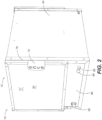
Fig. 2 is a perspective view of a sanitation chamber in a closed position; -
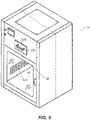
Fig. 3 is a cut away perspective view of a sanitation chamber; -
Fig. 4 is a schematic diagram of a timing circuit of a sanitation chamber; -
Fig. 5 is a schematic diagram of an agricultural facility; -
Fig. 6 is a schematic diagram of a lighting system; -
Fig. 7 is a decision flow chart of a method of sanitizing an agricultural facility; -
Fig. 8 is a schematic diagram of a sanitation chamber; -
Fig. 9 is a perspective view of a sanitation chamber; and -
Fig. 10 is a front plan view with hidden lines of a sanitation chamber. - In aspects not being part of the present invention:
Figures 1-3 depict achamber 10 having abody 12 that in an embodiment is generally shaped like a box, or has a rectangular cross section. In particular, in this aspect thebody 12 has aframe 14 withfirst support members 16 running in parallel spaced relation in an X-axis,second support members 18 running in parallel spaced relation in a Y-axis and perpendicular to the first support members andthird support members 20 running in parallel spaced relation in a Z-axis perpendicular to both first andsecond support members frame 14 having a square or rectangular cross section. - The first, second and
third support members second sidewalls top wall 26 andbottom wall 28. First andsecond door members second sidewalls door members second sidewalls door members bottom walls - The interior of the chamber includes a
retractable tray member 36 on which one ormore items 38 such as clothing, pieces of jewelry, feed, packages, water containers, tools, beverage containers and the like can be placed. In an example, thetray member 36 is within tracks and slides outwardly until engaging a stop member. In other examples thetray member 36 is on rollers and again engages a stop member when extended. By having twoseparate door members tray member 36 an individual can place theitems 38 into thefirst door member 30, then go through decontamination themselves, and then get theiritems 38 through theopposite door member 32. This provides a user with additional flexibility and functionality regarding where to locate the UV reflective material. Thereflective plate 54 surroundsattachment members 56 such as c-shaped clamps. In this example the lighting device has a transparenttubular body 58 that preferably is made of a material that absorbs a minimal amount of UV wavelength light, or a wavelength between 100 nanometers (nm) and 400 nm, more preferably 200 nm - 300 nm, even more preferably between 250 nm - 260 nm, and more preferably approximately 254 nm, to the interior of thechamber 10. - In this example a
first light holder 52 is secured to thebody 12 of thechamber 10 running along the corner of thechamber 10 created between thefirst sidewall 22 and thetop wall 26 and extending the length of theinterior 34. When in place the PCB is angled at the center oftray member 36 and thereflective plate 54 arcuately extends around the tube in approximately a half circle such that a maximum amount of light is directed directly at thetray member 36. Similarly asecond light holder 52 extends in the opposite corner of thechamber 10 adjacent thesecond sidewall 24 andtop wall 26 again having thesame light holder 52 and with the UV radiation toward thetray member 36. While these lighting devices have been described as on alight holder 52, the lighting devices could be secured directly to thechamber 10 or other similar mounting means without falling outside the scope of this disclosure. Also, while thelighting device 50 has been described as UV wavelength as described above angled toward thetray member 36. Thelighting device 50 in one example has anelectrical connector 63 that can only be inserted our actuated with a predetermined connector. In this manner, if an individual were to remove the chamber, they would be unable to power thelighting device 50 from a common power source or common means to ensure UV reflective material that absorbs a minimal amount of UV reflective materials the chamber maximizes the effect of UV radiation is maximized. - A
control panel 80 is disposed below eachdoor member emergency stop button 82, atimer button 84 and anindicator light 86. Disposed within and originating from a compartment within thechamber 10 iselectrical wiring 88 for theelectronic components UV lighting devices 50 that only plug into the connector of the UV light that can be harmful to the eyes of humans cannot be emitted by thelighting devices 50 when adoor member - In
Figure 4 , atiming circuit 102 is connected to the input line L and neutral line N and is electrically connected to thetimer button 84, such that when bothdoor members timing circuit 102 is actuated. The timing circuit provides current to the ballasts (BL1 and BL2, and BAL1 and BAL2) oflighting devices 50 for a predetermined period of time. In one example the predetermined period is approximately two minutes. The predetermined amount of time can be several seconds to several days without falling outside the scope of this disclosure. - The
timing circuit 102 is also connected in parallel with the ballast (BL1 and BL2, and BALI and BAL2) for thelighting devices 50 indicator lights 86 (LT1 and LT2) such that while thelighting devices 50 receive current the indicator lights 86 similarly receive current and lights to provide a warning to users that thechamber 10. This provides a warning to a user that thedoor members - In operation, the
chamber 10 is placed at the entrance of a swine facility. When an individual comes to the swine facility, before entering the individual takes any packages, feed, water, jewelry, shoes, clothing tools, or the like and takessuch items 38 and places them on thetray member 36. At this time the individual closes thechamber 10, ensuring thedoor members timer button 84. If bothdoor members electrical system 100 will not actuate as a result of the switches SW1 and SW2 and circuit relays C1 and thelighting devices 50 do not emit chamber and be harmful to a user. - If the
door members timing circuit 102. Thus, when thetimer button 84 is actuated current flows to the ballasts (BL1 and BL2, and BALI and BAL2) oflighting devices 50 to direct UV radiation is present and thedoor members 30 should remain closed. In an example, the magnetic interlocking prevents opening of thedoor members door member lighting devices 50 and the indicator lights 86 shut off. If a malfunction occurs and current continues to flow to the ballasts (BL1 and BL2, and BAL1 and BAL2) oflighting devices 50 and the indicator lights 86 remain on, a user recognizing this can actuate an emergency stop switch (ES1 or ES2) by actuating theemergency stop button 82. - Thus multiple methods are presented to minimize and eliminate an individual from being exposed to potentially harmful UV radiation radiates the item or
items 38. Thus if a germ, microorganism, virus or the like is on theitem 38 it is exposed to the UV radiation is absorbed by DNA of these microorganisms breaking the molecular bonds within the micro-organismal DNA, producing thymine dimers in the DNA preventing the DNA from replicating. In this manner, cells and viruses become inactive and unable to reproduce. Thus, if a virus such as the porcine epidemic diarrhea virus is on anitem 38 the exposure to the UV agricultural facility, including for chickens, turkeys, cows, horses and the like and to inactivate or kill any germ, microorganism, virus or the like, both without falling outside the scope of this disclosure. In particular, the agricultural facility. -
Figures 5-7 show another embodiment to accomplish sanitizing an agricultural facility. Theagricultural facility 110 hasmultiple rooms 112 for housing bothlivestock 114 andhumans 116. Within at least oneroom 112 is abiosecurity system 118. The biosecurity system includes alighting system 120 and abiosecurity chamber 10. - The
lighting system 120 comprises afirst lighting element 122 that emits light at a predetermined color and asecond lighting element 124 that emits light at a second predetermined color. In one example thefirst lighting element 122 emits white light and thesecond lighting element 124 emits light at a wavelength that promotes biosecurity. In one example thesecond lighting element 124 emits light having a narrow band of wavelength in the blue wavelength range. In one example the first andsecond lighting elements second lighting elements second lighting elements - A
controller 126 is electrically and operably connected to the first andsecond lighting elements lighting elements second switching elements controller 126 actuates thefirst switching element 128 thefirst lighting element 122 emits light and when thesecond switching element 130 is actuated thesecond lighting element 124 emits light. - The
controller 126 is also electrically connected to and receives information fromsensor 132 andauxiliary sensor 134. Thesensor 132 in one example is a motion detector that determines when an individual is within a predetermined space. Theauxiliary sensor 134 determines an environmental condition associated with theroom 112 in which theauxiliary sensor 134 is located. In an example, the environmental condition is the humidity within theroom 112, and in another example the environmental condition is the temperature within theroom 112. Similarly, theauxiliary sensor 134 could be designed to detect bacteria, a virus or predetermined chemical presence within theroom 112 or a space where the second sensor is located. - The
controller 126 is also electrically connected to and receives information from atimer 136. Specifically the controller has logic circuitry 138 therein that utilizes adecision matrix 140 based upon the inputs received from the first andsecond sensors timer 136 to determine when to actuate first andsecond switching elements second lighting elements -
Fig. 7 shows one example of thedecision matrix 140. When thelighting system 120 is operating thefirst sensor 132 is operational to detect the presence of an individual atstep 142. If an individual is detected, then thefirst switching element 128 is actuated and thefirst lighting element 122 is actuated such that white light is provided for the individual as indicated bystep 144. If an individual is not detected, then thesecond lighting element 124 is actuated at a predetermined wavelength, such as blue light to inhibit bacteria growth as indicated bystep 146. Thefirst sensor 132 continues to monitor for the presence of an individual after either step 144 or 146 atsteps step 152 or continues to emit the blue light atstep 154. If an individual is detected, then the first andsecond switching elements second lighting element 124 is turned off or kept off while thefirst lighting element 122 remains on atstep 156 or is turned on to provide white light atstep 158. In an alternative example, the decision matrix may return to step 142 after enteringstep 144 or step 146 and a predetermined period of time has elapsed. - The
decision matrix 140 can be accomplished in many different manners, including but not limited to utilizing a dimming system wherein a leading edge dimmer actuates thefirst switching element 128 and a falling edge dimmer controls thesecond switching element 130. In all, thedecision matrix 140 can be adjusted to include a timing circuit and to have the first andsecond lighting elements auxiliary sensor 134 can monitor humidity levels or other environmental conditions to detect an environment that is conductive for bacteria, viruses or other germs and adjusts thelighting system 120 to counteract the conditions by adding light, such as blue light into the environment. Thus thelighting system 120 can adjust to provide lighting for humans and still maximize biosecurity advantages. - To additionally sanitize the
facility 110, in one example anozone generator 160 is provided that generates or discharges ozone into aroom 112. In one example, theozone generator 160 is a corona discharge ozone generator. In another example, theozone generator 160 is in communication with thesensors timer 136 to only generate ozone when a human is not detected in thefacility 110 or at a time humans are not allowed into thefacility 110. In another example, the environmental condition detected by asensor facility 110 orroom 112 of thefacility 110 and theozone generator 160 is in communication with a security system of thefacility 110 to keep doors of thefacility 110 locked until a safe level of ozone for humans is within the facility. -
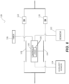
Fig. 8 shows another example embodiment of thechamber 10. Anozone generator 310 in one example has anair intake 312 andwater intake 314 to generate O3 throughozone outlet port 316 andwater outlet port 318. The water from thewater outlet port 318 flows to aradiator 320 positioned adjacent afan element 322 to move heated water vapor through anozone discharge port 324 to discharge air and ozone into thechamber 10. Theozone generator 310 in one example generate ozone through a corona discharge. The ozone combines with either UV light or blue light to become even more effective at killing and inactivating bacteria and viruses. - An
ozone filter system 326 is secured to the chamber to ensure when thechamber 10 is opened that harmful levels of ozone do not exist. Thefilter system 326 includes acarbon filter 328 that has anintake fan 330 and in one example utilizes active charcoal. In one example thefilter 328 has ahandle 329 and is removable and thus easily replaced with another filter. Aconduit 332 conveys the filtered oxygen back into the interior of thechamber 10. The timing circuit of thechamber 10 is electrically connected to theozone generator 310 to keep the door of the chamber locked for a predetermined period after shutting off thegenerator 310 to filter the air to have a safe level of ozone for humans before thechamber 10 can be opened. - One will appreciate that by using the
chamber 10 with theozone generator 310 andlighting system 120 that bacteria and viruses within anagricultural facility 110 are minimized to prevent the spread of disease. Consequently disease is prevented and facilities are saved from massive losses. Thus, at the very least all of the problems of the background have been overcome. - In the present invention a method of sanitizing an agricultural facility is provided that includes monitoring at least one room of an agricultural facility with a sensor to detect a human. A first light is provided having a first spectral content when a human is detected. A second light is provided having a second spectral content within a narrow range of wavelengths to inhibit bacteria growth when a human is not detected.
- In one example, the narrow range of wavelengths is in between 410nm-450nm. In another example, the narrow range of wavelengths is in the blue range of wavelengths. In yet another example, the sensor is a motion detector.
- In one example an additional step of monitoring the room with an auxiliary sensor and providing the second spectral content based on an environmental condition of the room detected by the auxiliary sensor is provided. In another example, the first light is provided by a light emitting diode. In yet another example, an additional step of discharging ozone into the room for a predetermined period when a human is not detected is provided. In one example, the ozone is discharged by corona discharge.
- The above description includes references to the accompanying drawings, which form a part of the detailed description. The drawings show, by way of illustration, specific embodiments in which the invention can be practiced. These embodiments are also referred to herein as "examples." Such examples can include elements in addition to those shown or described. However, the present inventors also contemplate examples in which only those elements shown or described are provided. Moreover, the present inventors also contemplate examples using any combination or permutation of those elements shown or described (or one or more aspects thereof), either with respect to a particular example (or one or more aspects thereof), or with respect to other examples (or one or more aspects thereof) shown or described herein.
- In this document, the terms "a" or "an" are used, as is common in patent documents, to include one or more than one, independent of any other instances or usages of "at least one" or "one or more." In this document, the term "or" is used to refer to a nonexclusive or, such that "A or B" includes "A but not B," "B but not A," and "A and B," unless otherwise indicated. In this document, the terms "including" and "in which" are used as the plain-English equivalents of the respective terms "comprising" and "wherein." Also, in the following claims, the terms "including" and "comprising" are open-ended, that is, a system, device, article, composition, formulation, or process that includes elements in addition to those listed after such a term in a claim are still deemed to fall within the scope of that claim. Moreover, in the following claims, the terms "first," "second," and "third," etc. are used merely as labels, and are not intended to impose numerical requirements on their obj ects.
- Geometric terms, such as "parallel", "perpendicular", "round", or "square", are not intended to require absolute mathematical precision, unless the context indicates otherwise. Instead, such geometric terms allow for variations due to manufacturing or equivalent functions. For example, if an element is described as "round" or "generally round," a component that is not precisely circular (e.g., one that is slightly oblong or is a many-sided polygon) is still encompassed by this description.
- Method examples described herein can be machine or computer-implemented at least in part. Some examples can include a computer-readable medium or machine-readable medium encoded with instructions operable to configure an electronic device to perform methods as described in the above examples. An implementation of such methods can include code, such as microcode, assembly language code, a higher-level language code, or the like. Such code can include computer readable instructions for performing various methods. The code may form portions of computer program products. Further, in an example, the code can be tangibly stored on one or more volatile, non-transitory, or nonvolatile tangible computer-readable media, such as during execution or at other times. Examples of these tangible computer-readable media can include, but are not limited to, hard disks, removable magnetic disks, removable optical disks (e.g., compact disks and digital video disks), magnetic cassettes, memory cards or sticks, random access memories (RAMs), read only memories (ROMs), and the like.
- The above description is intended to be illustrative, and not restrictive. For example, the above-described examples (or one or more aspects thereof) may be used in combination with each other.
Claims (11)
- A method of sanitizing an agricultural facility comprising multiple rooms suitable for housing both livestock and humans, wherein at least one room of the agricultural facility includes a lighting system comprising a first lighting element for providing a first light and a second lighting element for providing a second light, the method comprising:monitoring the at least one room of the agricultural facility with a sensor to detect that a human is present in the at least one room;providing the first light in the room having a first spectral content when the human is present; andproviding the second light in the room having a second spectral content within a narrow range of wavelengths to inhibit bacteria growth when the human is not detected.
- The method of claim 1 wherein the narrow range of wavelengths is in between 410 nanometers and 450 nanometers.
- The method of claim 1 wherein the narrow range of wavelengths is in between 100 nanometers and 400 nanometers.
- The method of claim 1 wherein the narrow range of wavelengths is in a blue range of wavelengths.
- The method of claim 1 wherein the sensor is a motion detector.
- The method of claim 1 further comprising:monitoring the at least one room with an auxiliary sensor; andproviding the second spectral content based on an environmental condition of the room detected by the auxiliary sensor.
- The method of claim 6 wherein the auxiliary sensor detects at least one of: humidity,
temperature, a bacteria, a virus, and a predetermined chemical. - The method of claim 1 wherein the first light is provided by a light emitting diode.
- The method of claim 1 further comprising discharging ozone into the at least one room for a predetermined period when the human is not detected.
- The method of claim 9 wherein the ozone is discharged by corona discharge.
- The method of claim 1 wherein the first spectral content and the second spectral content are different.
Applications Claiming Priority (2)
| Application Number | Priority Date | Filing Date | Title |
|---|---|---|---|
| US201662286487P | 2016-01-25 | 2016-01-25 | |
| PCT/US2017/014743 WO2017132146A1 (en) | 2016-01-25 | 2017-01-24 | Biosecurity system for an agricultural dwelling |
Publications (3)
| Publication Number | Publication Date |
|---|---|
| EP3407734A1 EP3407734A1 (en) | 2018-12-05 |
| EP3407734A4 EP3407734A4 (en) | 2020-01-08 |
| EP3407734B1 true EP3407734B1 (en) | 2023-03-08 |
Family
ID=59399136
Family Applications (1)
| Application Number | Title | Priority Date | Filing Date |
|---|---|---|---|
| EP17744763.8A Active EP3407734B1 (en) | 2016-01-25 | 2017-01-24 | Biosecurity system for an agricultural dwelling |
Country Status (6)
| Country | Link |
|---|---|
| US (2) | US11376340B2 (en) |
| EP (1) | EP3407734B1 (en) |
| CN (1) | CN108777980A (en) |
| DK (1) | DK3407734T3 (en) |
| PL (1) | PL3407734T3 (en) |
| WO (1) | WO2017132146A1 (en) |
Families Citing this family (5)
| Publication number | Priority date | Publication date | Assignee | Title |
|---|---|---|---|---|
| DK3407734T3 (en) | 2016-01-25 | 2023-05-01 | Signify North America Corp | BIOSECURITY SYSTEM FOR AN AGRICULTURAL BUILDING |
| US11058889B1 (en) | 2017-04-03 | 2021-07-13 | Xiant Technologies, Inc. | Method of using photon modulation for regulation of hormones in mammals |
| CH715184A1 (en) * | 2018-07-18 | 2020-01-31 | Pharma Integration S R L | Arrangement for the contamination-free introduction of a sterile object from a container into a containment and method therefor. |
| CN111397021A (en) * | 2020-04-09 | 2020-07-10 | 安吉润风空气净化科技有限公司 | Intelligent disinfection purifier |
| IT202000023785A1 (en) * | 2020-10-26 | 2022-04-26 | Gianfranco Danti | IMPROVED STRUCTURE OF GAS DEBACTERIAL |
Family Cites Families (29)
| Publication number | Priority date | Publication date | Assignee | Title |
|---|---|---|---|---|
| US6254625B1 (en) | 1998-07-02 | 2001-07-03 | Cenayda V. Rosenthal | Hand sanitizer |
| US8754385B1 (en) * | 1999-06-01 | 2014-06-17 | Jose Gutman | Advanced system and method for ozone containing packaging for sanitizing application |
| US6800315B2 (en) | 2001-09-18 | 2004-10-05 | The Ohio State University Research Foundation | Methods for decontaminating shell eggs |
| WO2003078571A2 (en) * | 2002-02-14 | 2003-09-25 | Wen Sheree H | Anti-infection and toxin elimination device |
| US6913691B2 (en) | 2002-03-20 | 2005-07-05 | Cuno Incorporated | Controlled dosing of chlorine dioxide or other sanitizing agents into pressurized water systems |
| US7407624B2 (en) * | 2002-04-16 | 2008-08-05 | Prompt Care, Inc. | Method for abatement of allergens, pathogens and volatile organic compounds |
| US20070172560A1 (en) | 2004-02-10 | 2007-07-26 | Swift & Company | Methods of controlling microorganisms in packaged foods |
| US20050186108A1 (en) | 2004-02-20 | 2005-08-25 | William Michael Fields | Bio-air sterilization system |
| US20050276720A1 (en) | 2004-06-01 | 2005-12-15 | Correa Rafael S | System and method for providing germicidal lighting for poultry facilities |
| AU2007246922B2 (en) | 2006-04-11 | 2009-02-26 | Lionel Scott | Produce treatment method |
| US7905052B2 (en) * | 2006-11-20 | 2011-03-15 | Hurst William E | System of photomorphogenically enhancing plants |
| CA2702811A1 (en) | 2007-10-25 | 2009-04-30 | Innovotech Inc. | Natural photodynamic agents and their use |
| JP5047117B2 (en) * | 2008-10-20 | 2012-10-10 | パナソニック株式会社 | Lighting system for plant disease control |
| US20100266445A1 (en) | 2009-04-21 | 2010-10-21 | Kenneth L. Campagna | Portable antimicrobial ultra violet sterilizer |
| RU2431418C1 (en) | 2010-02-10 | 2011-10-20 | ЗАКРЫТОЕ АКЦИОНЕРНОЕ ОБЩЕСТВО "Научно-производственная компания "АВЕРС" | Method for extension of cooked sausage marketability period in distribution network |
| CN101966347B (en) * | 2010-08-16 | 2013-09-11 | 南通格林福得禽业科技有限公司 | Light source special for livestock and poultry building |
| WO2012141992A1 (en) | 2011-04-15 | 2012-10-18 | Boyle William P | Apparatus for sterilizing the inside of a container |
| MX345704B (en) | 2011-06-10 | 2017-02-10 | Novartis Tiergesundheit Ag | Bovine vaccines and methods. |
| KR20130004276U (en) * | 2011-12-30 | 2013-07-10 | 윤의식 | A structure preventing the inflow of bacterias and viruses for cattle shed |
| CN105163605B (en) * | 2012-08-28 | 2018-06-12 | 传感器电子技术股份有限公司 | The sterilization of ultraviolet light gradient, disinfection and storage system |
| KR101263488B1 (en) | 2012-10-26 | 2013-06-04 | 충남대학교산학협력단 | Disinfection and sterilization apparatus for livestock farm |
| US10455819B2 (en) | 2012-12-11 | 2019-10-29 | Signify North America Corporation | Methods for controlling sex of oviparous embryos using light sources |
| US8946653B2 (en) | 2013-03-14 | 2015-02-03 | Teleflex Medical Incorporated | UV-C catheter hub sterilization and data acquisition system |
| US9517280B2 (en) * | 2013-08-30 | 2016-12-13 | American Air & Water, Inc. | Ultraviolet disinfection lighting system |
| AU2015223112B2 (en) | 2014-02-28 | 2020-07-09 | Delos Living Llc | Systems, methods and articles for enhancing wellness associated with habitable environments |
| US20150343103A1 (en) | 2014-06-02 | 2015-12-03 | Once Innovations, Inc. | Uv chamber and method of sanitizing agricultural facilities using the same |
| WO2016081594A1 (en) | 2014-11-19 | 2016-05-26 | The General Hospital Corporation | System and method for photo-dynamic procedure |
| EP3278020B1 (en) * | 2015-03-25 | 2021-12-29 | Vitabeam Ltd. | Method and apparatus for stimulation of plant growth and development with near infrared and visible lights |
| DK3407734T3 (en) | 2016-01-25 | 2023-05-01 | Signify North America Corp | BIOSECURITY SYSTEM FOR AN AGRICULTURAL BUILDING |
-
2017
- 2017-01-24 DK DK17744763.8T patent/DK3407734T3/en active
- 2017-01-24 EP EP17744763.8A patent/EP3407734B1/en active Active
- 2017-01-24 CN CN201780017189.7A patent/CN108777980A/en active Pending
- 2017-01-24 PL PL17744763.8T patent/PL3407734T3/en unknown
- 2017-01-24 US US16/072,230 patent/US11376340B2/en active Active
- 2017-01-24 WO PCT/US2017/014743 patent/WO2017132146A1/en active Application Filing
-
2022
- 2022-05-27 US US17/826,339 patent/US20220280668A1/en active Pending
Also Published As
| Publication number | Publication date |
|---|---|
| WO2017132146A1 (en) | 2017-08-03 |
| PL3407734T3 (en) | 2023-07-17 |
| US20190269809A1 (en) | 2019-09-05 |
| EP3407734A1 (en) | 2018-12-05 |
| DK3407734T3 (en) | 2023-05-01 |
| EP3407734A4 (en) | 2020-01-08 |
| US20220280668A1 (en) | 2022-09-08 |
| CN108777980A (en) | 2018-11-09 |
| US11376340B2 (en) | 2022-07-05 |
Similar Documents
| Publication | Publication Date | Title |
|---|---|---|
| US20220280668A1 (en) | Biosecurity system using monitoring and sanitization for an agricultural dwelling | |
| US8696985B2 (en) | Foot/footwear sterilization system | |
| EP2651214B1 (en) | An insect trap | |
| US8784731B2 (en) | Foot/footwear sterilization system | |
| JP2019536492A (en) | Light control system and method for exposing a small portion of space to light within a predetermined spectral range at a predetermined threshold intensity | |
| CN109414519A (en) | Automatic disinfection system | |
| US20050276720A1 (en) | System and method for providing germicidal lighting for poultry facilities | |
| JP2020078479A (en) | Ultraviolet ray irradiation device | |
| WO2007103704A2 (en) | Organism growth suppression using ultraviolet radiation | |
| CN111120977B (en) | Lighting sterilization system | |
| KR101860078B1 (en) | Disinfection apparatus for bacteria of infectious diseases in building facilities | |
| US20220125966A1 (en) | System and method for reducing microorganisms | |
| KR20200065145A (en) | A device to fight harmful insects using a timer with ultraviolet sterilizing function | |
| US20150343103A1 (en) | Uv chamber and method of sanitizing agricultural facilities using the same | |
| CN2768782Y (en) | Large-blowing multi-chamber ultraviolet sterilizing ozone apparatus | |
| WO2020254557A1 (en) | Method, device and ventilation system for reducing the microbial pressure in an animal farm production facility | |
| GB2530384A (en) | Sterilisation device and method | |
| US20210275702A1 (en) | Disinfecting Light Fixture | |
| KR102281877B1 (en) | ICT LED Sterilization and disease Control System for Disinfection and Sterilization of peggery | |
| Liu et al. | A Self-sterilizing Toilet Seat with UVC Radiation | |
| US20210356150A1 (en) | Hvac air treatment system and method | |
| EP4359069A1 (en) | Light emitting unit based on led | |
| KR20220005956A (en) | Food distribution table with sterilization function and Sterilization structure for food distribution table used thereofor | |
| TR202019476U5 (en) | LIGHTING DEVICE THAT CAN DISINFECT WITH UV-C | |
| GB2595652A (en) | An ultraviolet light sterilisation luminaire and system |
Legal Events
| Date | Code | Title | Description |
|---|---|---|---|
| STAA | Information on the status of an ep patent application or granted ep patent |
Free format text: STATUS: THE INTERNATIONAL PUBLICATION HAS BEEN MADE |
|
| PUAI | Public reference made under article 153(3) epc to a published international application that has entered the european phase |
Free format text: ORIGINAL CODE: 0009012 |
|
| STAA | Information on the status of an ep patent application or granted ep patent |
Free format text: STATUS: REQUEST FOR EXAMINATION WAS MADE |
|
| 17P | Request for examination filed |
Effective date: 20180821 |
|
| AK | Designated contracting states |
Kind code of ref document: A1 Designated state(s): AL AT BE BG CH CY CZ DE DK EE ES FI FR GB GR HR HU IE IS IT LI LT LU LV MC MK MT NL NO PL PT RO RS SE SI SK SM TR |
|
| AX | Request for extension of the european patent |
Extension state: BA ME |
|
| DAV | Request for validation of the european patent (deleted) | ||
| DAX | Request for extension of the european patent (deleted) | ||
| RAP1 | Party data changed (applicant data changed or rights of an application transferred) |
Owner name: SIGNIFY NORTH AMERICA CORPORATION |
|
| RIC1 | Information provided on ipc code assigned before grant |
Ipc: A23L 3/26 20060101ALI20190826BHEP Ipc: A61N 5/00 20060101ALI20190826BHEP Ipc: A23L 3/3418 20060101AFI20190826BHEP Ipc: B65D 73/00 20060101ALI20190826BHEP Ipc: A61L 9/18 20060101ALI20190826BHEP |
|
| A4 | Supplementary search report drawn up and despatched |
Effective date: 20191211 |
|
| RIC1 | Information provided on ipc code assigned before grant |
Ipc: A61L 9/18 20060101ALI20191205BHEP Ipc: A23L 3/3418 20060101AFI20191205BHEP Ipc: A61N 5/00 20060101ALI20191205BHEP Ipc: A23L 3/26 20060101ALI20191205BHEP Ipc: B65D 73/00 20060101ALI20191205BHEP |
|
| STAA | Information on the status of an ep patent application or granted ep patent |
Free format text: STATUS: EXAMINATION IS IN PROGRESS |
|
| 17Q | First examination report despatched |
Effective date: 20200708 |
|
| STAA | Information on the status of an ep patent application or granted ep patent |
Free format text: STATUS: EXAMINATION IS IN PROGRESS |
|
| STAA | Information on the status of an ep patent application or granted ep patent |
Free format text: STATUS: EXAMINATION IS IN PROGRESS |
|
| GRAP | Despatch of communication of intention to grant a patent |
Free format text: ORIGINAL CODE: EPIDOSNIGR1 |
|
| STAA | Information on the status of an ep patent application or granted ep patent |
Free format text: STATUS: GRANT OF PATENT IS INTENDED |
|
| INTG | Intention to grant announced |
Effective date: 20220921 |
|
| GRAS | Grant fee paid |
Free format text: ORIGINAL CODE: EPIDOSNIGR3 |
|
| GRAA | (expected) grant |
Free format text: ORIGINAL CODE: 0009210 |
|
| STAA | Information on the status of an ep patent application or granted ep patent |
Free format text: STATUS: THE PATENT HAS BEEN GRANTED |
|
| AK | Designated contracting states |
Kind code of ref document: B1 Designated state(s): AL AT BE BG CH CY CZ DE DK EE ES FI FR GB GR HR HU IE IS IT LI LT LU LV MC MK MT NL NO PL PT RO RS SE SI SK SM TR |
|
| REG | Reference to a national code |
Ref country code: GB Ref legal event code: FG4D |
|
| REG | Reference to a national code |
Ref country code: CH Ref legal event code: EP Ref country code: AT Ref legal event code: REF Ref document number: 1551964 Country of ref document: AT Kind code of ref document: T Effective date: 20230315 |
|
| REG | Reference to a national code |
Ref country code: IE Ref legal event code: FG4D |
|
| REG | Reference to a national code |
Ref country code: DE Ref legal event code: R096 Ref document number: 602017066620 Country of ref document: DE |
|
| REG | Reference to a national code |
Ref country code: NL Ref legal event code: FP |
|
| REG | Reference to a national code |
Ref country code: DK Ref legal event code: T3 Effective date: 20230425 |
|
| REG | Reference to a national code |
Ref country code: LT Ref legal event code: MG9D |
|
| P01 | Opt-out of the competence of the unified patent court (upc) registered |
Effective date: 20230530 |
|
| PG25 | Lapsed in a contracting state [announced via postgrant information from national office to epo] |
Ref country code: RS Free format text: LAPSE BECAUSE OF FAILURE TO SUBMIT A TRANSLATION OF THE DESCRIPTION OR TO PAY THE FEE WITHIN THE PRESCRIBED TIME-LIMIT Effective date: 20230308 Ref country code: NO Free format text: LAPSE BECAUSE OF FAILURE TO SUBMIT A TRANSLATION OF THE DESCRIPTION OR TO PAY THE FEE WITHIN THE PRESCRIBED TIME-LIMIT Effective date: 20230608 Ref country code: LV Free format text: LAPSE BECAUSE OF FAILURE TO SUBMIT A TRANSLATION OF THE DESCRIPTION OR TO PAY THE FEE WITHIN THE PRESCRIBED TIME-LIMIT Effective date: 20230308 Ref country code: LT Free format text: LAPSE BECAUSE OF FAILURE TO SUBMIT A TRANSLATION OF THE DESCRIPTION OR TO PAY THE FEE WITHIN THE PRESCRIBED TIME-LIMIT Effective date: 20230308 Ref country code: HR Free format text: LAPSE BECAUSE OF FAILURE TO SUBMIT A TRANSLATION OF THE DESCRIPTION OR TO PAY THE FEE WITHIN THE PRESCRIBED TIME-LIMIT Effective date: 20230308 Ref country code: ES Free format text: LAPSE BECAUSE OF FAILURE TO SUBMIT A TRANSLATION OF THE DESCRIPTION OR TO PAY THE FEE WITHIN THE PRESCRIBED TIME-LIMIT Effective date: 20230308 |
|
| REG | Reference to a national code |
Ref country code: AT Ref legal event code: MK05 Ref document number: 1551964 Country of ref document: AT Kind code of ref document: T Effective date: 20230308 |
|
| PG25 | Lapsed in a contracting state [announced via postgrant information from national office to epo] |
Ref country code: SE Free format text: LAPSE BECAUSE OF FAILURE TO SUBMIT A TRANSLATION OF THE DESCRIPTION OR TO PAY THE FEE WITHIN THE PRESCRIBED TIME-LIMIT Effective date: 20230308 Ref country code: GR Free format text: LAPSE BECAUSE OF FAILURE TO SUBMIT A TRANSLATION OF THE DESCRIPTION OR TO PAY THE FEE WITHIN THE PRESCRIBED TIME-LIMIT Effective date: 20230609 Ref country code: FI Free format text: LAPSE BECAUSE OF FAILURE TO SUBMIT A TRANSLATION OF THE DESCRIPTION OR TO PAY THE FEE WITHIN THE PRESCRIBED TIME-LIMIT Effective date: 20230308 |
|
| PG25 | Lapsed in a contracting state [announced via postgrant information from national office to epo] |
Ref country code: SM Free format text: LAPSE BECAUSE OF FAILURE TO SUBMIT A TRANSLATION OF THE DESCRIPTION OR TO PAY THE FEE WITHIN THE PRESCRIBED TIME-LIMIT Effective date: 20230308 Ref country code: RO Free format text: LAPSE BECAUSE OF FAILURE TO SUBMIT A TRANSLATION OF THE DESCRIPTION OR TO PAY THE FEE WITHIN THE PRESCRIBED TIME-LIMIT Effective date: 20230308 Ref country code: PT Free format text: LAPSE BECAUSE OF FAILURE TO SUBMIT A TRANSLATION OF THE DESCRIPTION OR TO PAY THE FEE WITHIN THE PRESCRIBED TIME-LIMIT Effective date: 20230710 Ref country code: EE Free format text: LAPSE BECAUSE OF FAILURE TO SUBMIT A TRANSLATION OF THE DESCRIPTION OR TO PAY THE FEE WITHIN THE PRESCRIBED TIME-LIMIT Effective date: 20230308 Ref country code: CZ Free format text: LAPSE BECAUSE OF FAILURE TO SUBMIT A TRANSLATION OF THE DESCRIPTION OR TO PAY THE FEE WITHIN THE PRESCRIBED TIME-LIMIT Effective date: 20230308 Ref country code: AT Free format text: LAPSE BECAUSE OF FAILURE TO SUBMIT A TRANSLATION OF THE DESCRIPTION OR TO PAY THE FEE WITHIN THE PRESCRIBED TIME-LIMIT Effective date: 20230308 |
|
| PG25 | Lapsed in a contracting state [announced via postgrant information from national office to epo] |
Ref country code: SK Free format text: LAPSE BECAUSE OF FAILURE TO SUBMIT A TRANSLATION OF THE DESCRIPTION OR TO PAY THE FEE WITHIN THE PRESCRIBED TIME-LIMIT Effective date: 20230308 Ref country code: IS Free format text: LAPSE BECAUSE OF FAILURE TO SUBMIT A TRANSLATION OF THE DESCRIPTION OR TO PAY THE FEE WITHIN THE PRESCRIBED TIME-LIMIT Effective date: 20230708 |
|
| REG | Reference to a national code |
Ref country code: DE Ref legal event code: R097 Ref document number: 602017066620 Country of ref document: DE |
|
| PLBE | No opposition filed within time limit |
Free format text: ORIGINAL CODE: 0009261 |
|
| STAA | Information on the status of an ep patent application or granted ep patent |
Free format text: STATUS: NO OPPOSITION FILED WITHIN TIME LIMIT |
|
| PG25 | Lapsed in a contracting state [announced via postgrant information from national office to epo] |
Ref country code: SI Free format text: LAPSE BECAUSE OF FAILURE TO SUBMIT A TRANSLATION OF THE DESCRIPTION OR TO PAY THE FEE WITHIN THE PRESCRIBED TIME-LIMIT Effective date: 20230308 |
|
| 26N | No opposition filed |
Effective date: 20231211 |
|
| PGFP | Annual fee paid to national office [announced via postgrant information from national office to epo] |
Ref country code: NL Payment date: 20240125 Year of fee payment: 8 |