EP3406890A1 - Wärmeisoliertes lufteinlasssystem für einen verbrennungsmotor - Google Patents
Wärmeisoliertes lufteinlasssystem für einen verbrennungsmotor Download PDFInfo
- Publication number
- EP3406890A1 EP3406890A1 EP18171436.1A EP18171436A EP3406890A1 EP 3406890 A1 EP3406890 A1 EP 3406890A1 EP 18171436 A EP18171436 A EP 18171436A EP 3406890 A1 EP3406890 A1 EP 3406890A1
- Authority
- EP
- European Patent Office
- Prior art keywords
- air supply
- air
- cylinder head
- insert
- supply pipe
- Prior art date
- Legal status (The legal status is an assumption and is not a legal conclusion. Google has not performed a legal analysis and makes no representation as to the accuracy of the status listed.)
- Granted
Links
Images



Classifications
-
- F—MECHANICAL ENGINEERING; LIGHTING; HEATING; WEAPONS; BLASTING
- F02—COMBUSTION ENGINES; HOT-GAS OR COMBUSTION-PRODUCT ENGINE PLANTS
- F02F—CYLINDERS, PISTONS OR CASINGS, FOR COMBUSTION ENGINES; ARRANGEMENTS OF SEALINGS IN COMBUSTION ENGINES
- F02F1/00—Cylinders; Cylinder heads
- F02F1/24—Cylinder heads
- F02F1/42—Shape or arrangement of intake or exhaust channels in cylinder heads
- F02F1/4235—Shape or arrangement of intake or exhaust channels in cylinder heads of intake channels
- F02F1/4257—Shape or arrangement of intake or exhaust channels in cylinder heads of intake channels with an intake liner
-
- F—MECHANICAL ENGINEERING; LIGHTING; HEATING; WEAPONS; BLASTING
- F02—COMBUSTION ENGINES; HOT-GAS OR COMBUSTION-PRODUCT ENGINE PLANTS
- F02M—SUPPLYING COMBUSTION ENGINES IN GENERAL WITH COMBUSTIBLE MIXTURES OR CONSTITUENTS THEREOF
- F02M35/00—Combustion-air cleaners, air intakes, intake silencers, or induction systems specially adapted for, or arranged on, internal-combustion engines
- F02M35/10—Air intakes; Induction systems
- F02M35/10006—Air intakes; Induction systems characterised by the position of elements of the air intake system in direction of the air intake flow, i.e. between ambient air inlet and supply to the combustion chamber
- F02M35/10026—Plenum chambers
- F02M35/10052—Plenum chambers special shapes or arrangements of plenum chambers; Constructional details
-
- F—MECHANICAL ENGINEERING; LIGHTING; HEATING; WEAPONS; BLASTING
- F02—COMBUSTION ENGINES; HOT-GAS OR COMBUSTION-PRODUCT ENGINE PLANTS
- F02B—INTERNAL-COMBUSTION PISTON ENGINES; COMBUSTION ENGINES IN GENERAL
- F02B77/00—Component parts, details or accessories, not otherwise provided for
- F02B77/11—Thermal or acoustic insulation
-
- F—MECHANICAL ENGINEERING; LIGHTING; HEATING; WEAPONS; BLASTING
- F02—COMBUSTION ENGINES; HOT-GAS OR COMBUSTION-PRODUCT ENGINE PLANTS
- F02F—CYLINDERS, PISTONS OR CASINGS, FOR COMBUSTION ENGINES; ARRANGEMENTS OF SEALINGS IN COMBUSTION ENGINES
- F02F1/00—Cylinders; Cylinder heads
- F02F1/24—Cylinder heads
- F02F1/42—Shape or arrangement of intake or exhaust channels in cylinder heads
-
- F—MECHANICAL ENGINEERING; LIGHTING; HEATING; WEAPONS; BLASTING
- F02—COMBUSTION ENGINES; HOT-GAS OR COMBUSTION-PRODUCT ENGINE PLANTS
- F02F—CYLINDERS, PISTONS OR CASINGS, FOR COMBUSTION ENGINES; ARRANGEMENTS OF SEALINGS IN COMBUSTION ENGINES
- F02F1/00—Cylinders; Cylinder heads
- F02F1/24—Cylinder heads
- F02F1/42—Shape or arrangement of intake or exhaust channels in cylinder heads
- F02F1/4235—Shape or arrangement of intake or exhaust channels in cylinder heads of intake channels
-
- F—MECHANICAL ENGINEERING; LIGHTING; HEATING; WEAPONS; BLASTING
- F02—COMBUSTION ENGINES; HOT-GAS OR COMBUSTION-PRODUCT ENGINE PLANTS
- F02M—SUPPLYING COMBUSTION ENGINES IN GENERAL WITH COMBUSTIBLE MIXTURES OR CONSTITUENTS THEREOF
- F02M35/00—Combustion-air cleaners, air intakes, intake silencers, or induction systems specially adapted for, or arranged on, internal-combustion engines
- F02M35/10—Air intakes; Induction systems
-
- F—MECHANICAL ENGINEERING; LIGHTING; HEATING; WEAPONS; BLASTING
- F02—COMBUSTION ENGINES; HOT-GAS OR COMBUSTION-PRODUCT ENGINE PLANTS
- F02M—SUPPLYING COMBUSTION ENGINES IN GENERAL WITH COMBUSTIBLE MIXTURES OR CONSTITUENTS THEREOF
- F02M35/00—Combustion-air cleaners, air intakes, intake silencers, or induction systems specially adapted for, or arranged on, internal-combustion engines
- F02M35/10—Air intakes; Induction systems
- F02M35/10006—Air intakes; Induction systems characterised by the position of elements of the air intake system in direction of the air intake flow, i.e. between ambient air inlet and supply to the combustion chamber
- F02M35/10072—Intake runners
-
- F—MECHANICAL ENGINEERING; LIGHTING; HEATING; WEAPONS; BLASTING
- F02—COMBUSTION ENGINES; HOT-GAS OR COMBUSTION-PRODUCT ENGINE PLANTS
- F02M—SUPPLYING COMBUSTION ENGINES IN GENERAL WITH COMBUSTIBLE MIXTURES OR CONSTITUENTS THEREOF
- F02M35/00—Combustion-air cleaners, air intakes, intake silencers, or induction systems specially adapted for, or arranged on, internal-combustion engines
- F02M35/10—Air intakes; Induction systems
- F02M35/10242—Devices or means connected to or integrated into air intakes; Air intakes combined with other engine or vehicle parts
- F02M35/10268—Heating, cooling or thermal insulating means
-
- F—MECHANICAL ENGINEERING; LIGHTING; HEATING; WEAPONS; BLASTING
- F02—COMBUSTION ENGINES; HOT-GAS OR COMBUSTION-PRODUCT ENGINE PLANTS
- F02M—SUPPLYING COMBUSTION ENGINES IN GENERAL WITH COMBUSTIBLE MIXTURES OR CONSTITUENTS THEREOF
- F02M35/00—Combustion-air cleaners, air intakes, intake silencers, or induction systems specially adapted for, or arranged on, internal-combustion engines
- F02M35/10—Air intakes; Induction systems
- F02M35/1034—Manufacturing and assembling intake systems
- F02M35/10347—Moulding, casting or the like
-
- F—MECHANICAL ENGINEERING; LIGHTING; HEATING; WEAPONS; BLASTING
- F02—COMBUSTION ENGINES; HOT-GAS OR COMBUSTION-PRODUCT ENGINE PLANTS
- F02M—SUPPLYING COMBUSTION ENGINES IN GENERAL WITH COMBUSTIBLE MIXTURES OR CONSTITUENTS THEREOF
- F02M35/00—Combustion-air cleaners, air intakes, intake silencers, or induction systems specially adapted for, or arranged on, internal-combustion engines
- F02M35/10—Air intakes; Induction systems
- F02M35/104—Intake manifolds
-
- F—MECHANICAL ENGINEERING; LIGHTING; HEATING; WEAPONS; BLASTING
- F02—COMBUSTION ENGINES; HOT-GAS OR COMBUSTION-PRODUCT ENGINE PLANTS
- F02M—SUPPLYING COMBUSTION ENGINES IN GENERAL WITH COMBUSTIBLE MIXTURES OR CONSTITUENTS THEREOF
- F02M35/00—Combustion-air cleaners, air intakes, intake silencers, or induction systems specially adapted for, or arranged on, internal-combustion engines
- F02M35/12—Intake silencers ; Sound modulation, transmission or amplification
- F02M35/1272—Intake silencers ; Sound modulation, transmission or amplification using absorbing, damping, insulating or reflecting materials, e.g. porous foams, fibres, rubbers, fabrics, coatings or membranes
-
- F—MECHANICAL ENGINEERING; LIGHTING; HEATING; WEAPONS; BLASTING
- F16—ENGINEERING ELEMENTS AND UNITS; GENERAL MEASURES FOR PRODUCING AND MAINTAINING EFFECTIVE FUNCTIONING OF MACHINES OR INSTALLATIONS; THERMAL INSULATION IN GENERAL
- F16L—PIPES; JOINTS OR FITTINGS FOR PIPES; SUPPORTS FOR PIPES, CABLES OR PROTECTIVE TUBING; MEANS FOR THERMAL INSULATION IN GENERAL
- F16L59/00—Thermal insulation in general
- F16L59/14—Arrangements for the insulation of pipes or pipe systems
-
- F—MECHANICAL ENGINEERING; LIGHTING; HEATING; WEAPONS; BLASTING
- F02—COMBUSTION ENGINES; HOT-GAS OR COMBUSTION-PRODUCT ENGINE PLANTS
- F02F—CYLINDERS, PISTONS OR CASINGS, FOR COMBUSTION ENGINES; ARRANGEMENTS OF SEALINGS IN COMBUSTION ENGINES
- F02F2200/00—Manufacturing
- F02F2200/06—Casting
Definitions
- the invention relates to an air intake system for an internal combustion engine and to a method for producing an air intake system.
- the combustion chambers of an internal combustion engine are supplied with fresh air for combustion of the fuel via an air intake system.
- the air intake system has various air flow channels. These include the intake passage in the cylinder head, which opens into the combustion chamber. Upstream of the inlet channel, an air supply channel is arranged, which can distribute, for example, the intake air to one or more cylinders.
- the air intake system may include other components such as a compressor and a charge air cooler.
- the internal combustion engine heats up.
- the cylinder head mounted on the combustion chambers heats up.
- the intake air has a low temperature and thus a high density when flowing into the combustion chambers.
- the intake air may be heated by the compressor when compressed by a compressor or by heat transfer from the cylinder head heated during operation.
- the US 4,300,494 A discloses a gasoline engine with reduced fuel consumption.
- the internal combustion engine has an intake passage in the cylinder head which is coated with a heat-insulating material
- the DE 40 06 583 A1 discloses a diesel engine.
- An intake passage in the cylinder head of the diesel engine is provided with a heat-insulating lining made of a ceramic material.
- the JP2016118132 (A ) discloses a heat-insulating member for an intake passage in a cylinder head of an internal combustion engine.
- the known measures may be insufficient, so that the fresh air still flows with too high a temperature in the combustion chambers of the internal combustion engine.
- the invention is therefore based on the object to provide an air intake system that allows the supply of cool fresh air to the combustion chambers of an internal combustion engine.
- the air intake system includes a cylinder head having an intake passage for introducing intake air into a combustion chamber of the engine.
- the air intake system further includes an air supply pipe piece connected to the cylinder head and at least partially forming an air supply passage that opens into the intake passage.
- heat insulation is disposed in the air supply passage to reduce heat transfer to the intake air flowing in the air supply passage. By disposing the heat insulation, heating of the intake air as it flows through the air supply passage can be reduced. Due to the reduced heating of the intake air, the density of the intake air is not significantly reduced. Thus, more intake air can flow into the combustion chamber. This can increase the efficiency of the engine and thus help to consume less fuel.
- the air supply pipe piece may be formed as an air distribution pipe piece for distributing the intake air to a plurality of cylinders of the internal combustion engine.
- the air supply passage is located upstream of the intake passage.
- the thermal insulation may abut against an inner wall surface of the air supply channel.
- the air supply pipe section may have an open profile, for example a U-profile.
- the heat insulation may be made of an exhaust gas-resistant material, so that, for example, in embodiments with exhaust gas recirculation no impairment of the heat insulation by the exhaust gas occurs.
- the air intake system may include a compressor and / or intercooler upstream of the air supply tube.
- the cylinder head may be a single-cylinder cylinder head or a multi-cylinder cylinder head.
- the air supply pipe and the heat insulation are made of different materials.
- the air supply pipe piece can in particular be made of a metal alloy, preferably an aluminum alloy.
- the thermal insulation can be made in particular of a plastic, a rubber and / or a silicone.
- the air supply pipe piece can be made for example of a stable metal alloy, which has a high thermal conductivity.
- the thermal insulation may be made of a material having a low thermal conductivity.
- the thermal insulation may have a thermal conductivity that is smaller than a thermal conductivity of an outer wall of the air supply pipe section.
- the thermal insulation has a thermal conductivity of less than 1 W / (m ⁇ K), in particular less than 0.5 W / (m ⁇ K), preferably less than 0.1 W / (m ⁇ K).
- the air supply pipe piece is mounted to the cylinder head, in particular screwed.
- the air supply pipe piece and the cylinder head are formed integrally with each other in one piece and in particular form an integral casting.
- the proposed thermal insulation is thus suitable both in embodiments with anmont Arthurm air supply pipe section as well as in embodiments with cast air supply pipe piece.
- the thermal insulation has an insert, in particular a liner.
- the insert abuts an inner wall surface of the air supply channel.
- the insert may in particular have an adhesive layer for adhering the insert to the inner wall surface of the air supply channel.
- the insert is designed as a flexible, in particular foldable, insert. This can facilitate installation of the insert in the air supply duct.
- the insert is produced by a 3D printing process.
- 3D printing process Even complex geometry and filigree structures of the insert can be produced for reproducing an inner contour of the air supply channel with reasonable effort.
- the insert additionally acts as a seal at a junction between the cylinder head and the air supply pipe section.
- a seal between the air supply pipe piece and the cylinder head can be improved by the use.
- the thermal insulation has a coating.
- the coating is applied to an inner wall surface of the air supply channel.
- the coating may be applied by a spray-on process.
- the coating can be provided as an alternative or in addition to the insert (liner).
- the coating and the insert may be provided side by side or one above the other.
- the heat insulation is additionally designed to dampen an intake noise that occurs in the operation of the internal combustion engine in the air intake duct, and / or to acoustically insulate the intake duct.
- the thermal insulation for example, be designed to effect (eg increased or significant) reflection of airborne sound in the air intake duct (insulation) or to reduce a sound intensity by absorption (damping). This may in particular mean that a noise perceived outside the air supply pipe section is reduced in volume and / or changed in a frequency range.
- the acoustic effect can be brought about in particular by a shape and / or a material / material mix of the thermal insulation.
- the thermal insulation is additionally arranged in the inlet channel of the cylinder head.
- the heat insulation in the inlet channel may have a coating on an inner wall surface of the inlet channel and / or on the inner wall surface, in particular flexible, preferably foldable insert, for example a liner. This has the advantage that heating of the intake air can be reduced not only in the air supply passage but also in the intake passage.
- the inlet channel is in particular curved.
- the inlet channel opens to the combustion chamber.
- a combustion chamber opening of the inlet channel can be closed by a lift valve (poppet valve).
- the air supply channel can be substantially straight.
- the air supply duct (the air supply pipe section) may in particular run along a series of juxtaposed cylinders of the internal combustion engine.
- the air supply passage may be formed as an air supply distribution passage having a plurality of outlets for a plurality of intake passages.
- the intake ports may lead to the same or, in particular, to multiple combustion chambers of the internal combustion engine.
- the air supply pipe piece is designed in particular as a load-bearing element and / or as a casting, preferably a metal casting, for mounting one or more components of the internal combustion engine.
- the cylinder head partially forms the air supply passage.
- the cylinder head forms an outlet region of the air supply channel which opens into the inlet channel.
- the air supply pipe piece completely forms the air supply passage.
- the wall thickness of the thermal insulation can be chosen so that a sufficient thermal insulation of the intake air is ensured in the air supply channel.
- the wall thickness of the air supply pipe section may be selected so that a supporting function of the air supply pipe section is ensured.
- the thermal insulation and the air supply pipe section define a common wall thickness of the air supply duct.
- the thermal insulation has a wall thickness in an area smaller than 50% of the common wall thickness, in particular between 30% and 40% of the common wall thickness. This can on the one hand achieved a good thermal insulation and on the other hand a supporting function of the air supply pipe piece are made possible.
- the thermal insulation may, for example, have a thickness of about 3 mm, preferably less than 3 mm.
- the invention further relates to a motor vehicle, in particular utility vehicle, with an air intake system as disclosed herein.
- the invention also relates to a method for producing an air intake system of an internal combustion engine.
- the method includes casting a cylinder head having an inlet channel and a molded air supply tube.
- the air supply pipe piece forms with the cylinder head an air supply passage which opens into the intake passage.
- the inlet channel has a combustion chamber opening and the air supply channel has an inlet opening for Intake air on.
- the method further comprises introducing a thermal insulation having a folded insert, in particular a liner, through the combustion chamber opening or the inlet opening into the air supply channel.
- the method also includes deploying the insert in the air supply channel such that the insert engages an inner wall surface of the air supply channel.
- a thermal insulation can be arranged in a molded air supply pipe piece.
- the invention relates to another method for producing an air intake system of an internal combustion engine.
- the method includes casting an air supply pipe piece for mounting to a cylinder head.
- the air supply pipe piece is mountable such that an air supply duct formed at least partially by the air supply pipe piece opens into an intake passage of the cylinder head.
- the method comprises coating an inner wall surface of the air supply channel with a coating as a thermal insulation.
- the method may comprise inserting or inserting an insert, in particular a liner, as a thermal insulation in the air supply channel.
- the method further includes mounting the air supply pipe piece to the cylinder head.
- thermal insulation can be arranged in various ways in an attached air supply pipe.
- the mounting of the air supply pipe piece can take place, in particular, before the insertion of the insert, after inserting the insert or after coating an inner wall surface.
- the insert may be folded into the air supply duct through an inlet opening of the air supply duct or a combustion chamber opening of the inlet duct and deployed in the air supply duct.
- the methods of making an air intake system can manufacture the air intake system disclosed herein.
- the FIG. 1 shows a cylinder head 10 and an air supply pipe section 12 of an internal combustion engine, not shown.
- the internal combustion engine can be used, for example, for driving a commercial vehicle.
- the commercial vehicle may in particular be a bus or a lorry.
- the air supply pipe piece 12 is connected to the cylinder head 10.
- the cylinder head 10 and the air supply pipe 12 form an air intake system 14.
- the air intake system 14 may be a charge air system or an intake system.
- the cylinder head 10 is shown without air supply pipe section 12.
- the air supply pipe section 12 is shown without the cylinder head 10.
- the cylinder head 10 may be mounted to seal one or more cylinders on an engine block of an internal combustion engine (not shown).
- the cylinder head 10 is a multi-cylinder cylinder head mountable on a plurality of juxtaposed cylinders.
- the cylinder head may be formed as a single-cylinder cylinder head for a single cylinder.
- the cylinder head 10 has a plurality of inlet channels 16, which lead in the assembled state to combustion chambers of the internal combustion engine.
- Intake air fresh air
- additional recirculated exhaust gas and / or an air-fuel mixture may be directed into the combustion chambers through the intake ports 16.
- the intake air is passed through an air supply passage 18 (see Figures 1 and 2B ) are directed to the inlet channels 16.
- the air supply channel 18 opens into the inlet channels 16.
- the air supply pipe section 12 can be mounted on the cylinder head 10 via a plurality of screw connections. Specifically, screws (not shown) may be passed through screw holes 20 in the air supply pipe section 12 and screwed into corresponding receiving bores 22 in the cylinder head 10. For reasons of clarity are in the Figures 1, 2A and 2B only two screw holes 20 and two receiving holes 22 are designated.
- the air supply passage 18 is formed between the cylinder head 10 and the air supply pipe 12.
- the air supply pipe piece 12 has an open profile which matches an open profile on the cylinder head 10.
- the open profile of the air supply pipe section 12 is a U-profile. Depending on the requirements and space but other profile shapes for the air supply pipe section 12 are conceivable.
- the air supply duct 18 may be completely formed by the air supply duct 12. It is also possible that the air supply pipe section 12 is cast directly on the cylinder head 10. In other words, the cylinder head 10 may be cast together with the air supply pipe 12 in a casting operation as an integral casting. Here, the cylinder head 10 forms, for example, an outlet region of the air supply channel 18 which opens into the inlet channels 16.
- the air supply channel 18 extends substantially straight in a longitudinal direction along (a longitudinal direction) of the cylinder head 10.
- a profile of the air supply channel 18 may be adapted to the arrangement of peripheral components, for example, to bypass the peripheral components.
- the air supply channel 18 is formed as a distribution channel. From an inlet opening 24, the inlet air is directed from the air supply channel 18 to the plurality of inlet channels 16.
- the inlet opening 24 may be disposed at one end of the air supply pipe piece 12 and / or at any position between both ends of the air supply pipe piece 12.
- the air supply channel 18 may have a plurality of outlets for the plurality of inlet channels 16.
- the air supply pipe piece 12 may be formed as an air supply distribution pipe piece.
- the air supply pipe section 12 is formed as a supporting element, on which one or more further components of the internal combustion engine can be mounted.
- the air supply pipe piece 12 is in particular made of a metal alloy, for example an aluminum alloy.
- the air supply pipe section 12 may be a cast part, for example a diecast part.
- the air intake system 14 may additionally include a charge air cooler (not shown) and / or a compressor (not shown).
- the charge air cooler and the compressor may be arranged upstream of the inlet opening 24 of the air supply pipe section 12 (the air supply channel 18).
- the compressor may compress intake air and be part of a turbocharger, for example.
- the intercooler for example, cooled by a compression heated intake air when flowing through.
- FIGS. 3 to 6 are sectional views through different charge air systems according to the present disclosure.
- the sectional plane is chosen so that in each case a central axis A of the inlet channel 16 extends in the sectional plane.
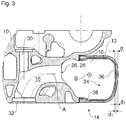
- FIG. 3 shows an embodiment in which the cylinder head 10 and the air supply pipe piece 12 are formed separately.
- the air supply pipe section 12 is as described above with reference to FIGS FIGS. 1 to 2B explained, bolted to the cylinder head 10.
- the air supply channel 18 extends straight along a longitudinal axis B.
- the longitudinal axis B is substantially perpendicular to the central axis A of the inlet channel 16.
- the longitudinal axis B is substantially perpendicular to all central axes A of a plurality of inlet channels 16.
- the intake air flowing in the air supply passage 18 flows through an exhaust port 26 of the air supply passage 18 into an intake port 28 of the intake passage 16.
- the air then flows into a combustion chamber.
- the inlet channel 16 may partially a lift valve (not shown), in particular a poppet valve, extend.
- the lift valve is mounted in a receptacle 30 and serves to open and close a combustion chamber opening 32 of the inlet channel 16.
- a heat insulation 34 is arranged in the air supply channel 18.
- the thermal insulation 34 reduces heat transfer to the intake air flowing through the air supply passage 18.
- the heat comes in particular from the cylinder head 10 heated during operation and the ambient air of the internal combustion engine heated during operation.
- the thermal insulation 34 may be made of a plastic, for example a thermoplastic, a rubber and / or a silicone.
- silicones come in particular silicones for the automotive industry in question.
- the rubber for example, FKM (fluorocarbon rubber) or FPM (fluoropolymer rubber) can be used.
- the heat insulation 34 is in particular made of a different material than the air supply pipe piece 12. While the air supply pipe piece 12 is formed of a workable material such as a metal having a large heat conductivity, the heat insulation 34 has a very low thermal conductivity.
- the thermal conductivity of the thermal insulation 34 is for example less than 5 W / (m ⁇ K), in particular less than 1 W / (m ⁇ K), preferably less than 0.1 W / (m ⁇ K).
- the thermal insulation 34 may have a smooth surface to allow the most uniform flow through the air supply channel 18.
- the thermal insulation 34 has a coating 36.
- the coating 36 at least partially covers an inner wall surface 38 of the air supply duct 18 (air supply pipe section 12).
- the coating 36 may be applied, for example, via a spraying process (eg an injection molding process).
- a spray-on process for example, a carbon fiber-reinforced thermoplastic, for example PA66-CF35, can be applied.
- a spray-on process for example, a carbon fiber-reinforced thermoplastic, for example PA66-CF35, can be applied.
- PA66-CF35 e.
- other coating methods are conceivable.
- the coating 36 is applied to the inner wall surface 38 prior to assembly of the air supply tube 12 to the cylinder head 10.
- the air supply channel 18 has a wall thickness d.
- the wall thickness d results as the sum of the wall thickness (thickness) d 1 of the coating 36 (heat insulation 34) and the wall thickness d 2 of the outer wall of the air supply pipe piece 12.
- the wall thickness d 1 of the coating 36 may, for example, be dimensioned to be approximately in a range between 30% and 40% of the wall thickness d.
- the wall thickness of the thermal insulation 34 is chosen in particular so that in fact a sufficient heat-insulating effect is achieved.
- FIG. 4 shows an embodiment in which the cylinder head 10 and the air supply pipe piece 12 are integrally formed as a casting.
- the air supply pipe piece 12 is cast on the cylinder head 10. Specifically, the air supply pipe piece 12 and the cylinder head 10 were formed in a common casting process.
- the thermal insulation 34 is formed as an insert 40 in the form of a liner.
- the insert 40 is disposed in the air supply channel 18 and extends into the inlet channel 16.
- the insert 40 abuts against the inner wall surface 38.
- the insert 40 may be single-layered or multi-layered.
- the insert 40 may be formed in one piece or in several parts. In the illustrated embodiment, the insert 40 extends partially into the inlet channel 16.
- the insert 40 may have an adhesive layer (adhesive layer) or a plurality of splices, with which the insert 40 is glued to the inner wall surface 38.
- the insert 40 may also be secured to the interior wall by any other suitable fastening means.
- An outer contour of the insert 40 forms a contour of the inner wall surface 38 and therefore rests against the inner wall surface 38.
- the overpressure presses the insert 40 against the inner wall surface 38 and prevents accidental slippage of the insert 40.
- a negative pressure in the air supply channel 18 prevail even with supercharged engines, so here too Precautions should be taken to prevent detachment of the insert from the inner wall surface.
- the insert 40 may be flexible, so that it is particularly foldable.
- the insert 40 may in the folded state through the combustion chamber opening 32 or the inlet opening 24 (see FIG. 1 ) are introduced into the air supply channel 18.
- the insert 40 can be deployed and invest in the inner wall surface 38.
- the insert 40 may also be used in embodiments in which the air supply tube piece 12 is mounted to the cylinder head 10.
- the insert 40 may be inserted into the air supply pipe section 12 prior to assembly of the air supply pipe section 12. It is also possible that the insert 40 after the assembly of the air supply pipe piece 12 through the combustion chamber opening 32 or the inlet opening 34 (see FIG. 1 ) is introduced into the air supply channel 18.
- the insert 40 may be sized to cover an interface (transition) between the cylinder head 10 and the air supply tube 12.
- the insert 40 may additionally serve as a seal between the cylinder head 10 and the air supply pipe section 12.
- the insert 40 may be made, for example, by a 3D printing process. In such a 3D printing process, the insert 40 may be printed, for example, as a thermoplastic polyurethane from a 3D printer.
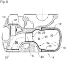
- FIG. 5 shows a further embodiment in which the heat insulation 34 is additionally partially disposed in the inlet channel 16.
- the insulation 34 is formed by a coating 36 and an insert 40.
- the insert 40 extends in an outlet region of the air supply channel 18 and partially in the inlet channel 16.
- the insert 40 may be similar to the insert 40 of FIG. 4 be prepared and positioned embodiment described.
- the insert 40 may be configured to cover a contact area between the cylinder head 10 and the air supply pipe section 12 for sealing (not shown).
- the thermal insulation 34 may additionally include in the inlet channel 16 a coating of an inner wall surface of the inlet channel 16 and / or an insert adjacent an inner wall surface of the inlet channel 16.
- FIG. 6 shows a further embodiment in which the heat insulation 34 is formed by a arranged in the air supply passage 18 insert 40.
- the air supply pipe section 12 is provided merely as a kind of cover bolted to the cylinder head 10.
- the air supply passage 18 is largely formed by the cylinder head 10.
- the insert 40 can be introduced, for example, through the combustion chamber opening 32 or an inlet opening of the air supply channel 18 and deployed in the air supply channel 18 with an already mounted air supply pipe section 12.
- air inlet systems disclosed herein may utilize various methods of manufacture that can be combined depending on the design of the thermal insulation.
- the insert 40 may be inserted through the combustion chamber opening 32 or the inlet opening 24 into the air supply channel 18.
- the insert 40 is folded before insertion.
- the insert 40 is deployed.
- the insert 40 then applies with its adapted outer contour to the inner contour of the air supply channel 18.
- the insert 40 may be disposed on the cylinder head 10 in the air supply passage 18 before or after mounting the air supply pipe piece 12.
- the insert 40 may be inserted into the air supply pipe piece 12 before mounting the air supply pipe piece 12 to the cylinder head 10.
- the insert 40 may preferably be inserted after mounting the air supply pipe piece 12 to the cylinder head 10 through the combustion chamber opening 32 or the inlet opening 24.
- the coating 36 can be applied, in particular, prior to mounting the air supply pipe piece 12.
Landscapes
- Engineering & Computer Science (AREA)
- General Engineering & Computer Science (AREA)
- Mechanical Engineering (AREA)
- Chemical & Material Sciences (AREA)
- Combustion & Propulsion (AREA)
- Physics & Mathematics (AREA)
- Geometry (AREA)
- Manufacturing & Machinery (AREA)
- Acoustics & Sound (AREA)
- Cylinder Crankcases Of Internal Combustion Engines (AREA)
Abstract
Description
- Die Erfindung betrifft ein Lufteinlasssystem für einen Verbrennungsmotor und Verfahren zur Herstellung eines Lufteinlasssystems.
- Den Verbrennungskammern eines Verbrennungsmotors wird Frischluft zur Verbrennung des Kraftstoffs über ein Lufteinlasssystem zugeführt. Das Lufteinlasssystem weist verschiedene Luftströmungskanäle auf. Hierzu zählt der Einlasskanal im Zylinderkopf, der in die Verbrennungskammer mündet. Stromaufwärts des Einlasskanals ist ein Luftzufuhrkanal angeordnet, der beispielsweise die Einlassluft zu einem oder mehreren Zylindern verteilen kann. Das Lufteinlasssystem kann weitere Komponenten, wie beispielsweise einen Verdichter und einen Ladeluftkühler aufweisen.
- Beim Betrieb des Verbrennungsmotors erwärmt sich der Verbrennungsmotor. Insbesondere erwärmt sich der auf die Verbrennungskammern montierte Zylinderkopf. Es ist wünschenswert, dass die Einlassluft beim Einströmen in die Verbrennungskammern eine niedrige Temperatur und somit eine hohe Dichte aufweist. Die Einlassluft kann sich beispielsweise beim Verdichten durch einen Verdichter oder durch eine Wärmeübertragung von dem im Betrieb erwärmten Zylinderkopf erwärmen.
- Die
US 4,300,494 A offenbart einen Ottomotor mit verringertem Kraftstoffverbrauch. Der Verbrennungsmotor weist einen Einlasskanal im Zylinderkopf auf, der mit einem wärmeisolierenden Material beschichtet ist - Die
DE 40 06 583 A1 offenbart einen Dieselmotor. Ein Ansaugkanal im Zylinderkopf des Dieselmotors ist mit einer wärmeisolierenden Auskleidung versehen, die aus einem Keramikmaterial besteht. - Die
JP2016118132 (A - Die bekannten Maßnahmen können unzureichend sein, sodass die Frischluft noch immer mit einer zu hohen Temperatur in die Verbrennungskammern des Verbrennungsmotors einströmt.
- Der Erfindung liegt daher die Aufgabe zu Grunde, ein Lufteinlasssystem vorzusehen, das die Zuführung von kühler Frischluft zu den Verbrennungskammern eines Verbrennungsmotors ermöglicht.
- Die Aufgabe wird gelöst durch ein Lufteinlasssystem gemäß dem unabhängigen Anspruch. Herstellungsverfahren für das Lufteinlasssystem gemäß den unabhängigen Ansprüchen sind ebenfalls offenbart. Vorteilhafte Weiterbildungen sind in den abhängigen Ansprüchen und der Beschreibung angegeben.
- Das Lufteinlasssystem weist einen Zylinderkopf mit einem Einlasskanal zum Einleiten von Einlassluft in eine Verbrennungskammer des Verbrennungsmotors auf. Das Lufteinlasssystem weist ferner ein Luftzufuhrrohrstück, das mit dem Zylinderkopf verbunden ist und mindestens teilweise einen Luftzufuhrkanal, der in den Einlasskanal mündet, ausbildet, auf. Zudem ist eine Wärmeisolierung in dem Luftzufuhrkanal zur Verringerung einer Wärmeübertragung auf die in dem Luftzufuhrkanal strömende Einlassluft angeordnet. Durch Anordnung der Wärmeisolierung kann eine Erwärmung der Einlassluft beim Durchströmen des Luftzufuhrkanals verringert werden. Aufgrund der verringerten Erwärmung der Einlassluft reduziert sich die Dichte der Einlassluft nicht wesentlich. Somit kann mehr Einlassluft in die Verbrennungskammer strömen. Dies kann den Wirkungsgrad des Verbrennungsmotors erhöhen und somit dabei helfen, weniger Kraftstoff zu verbrauchen.
- Das Luftzufuhrrohrstück kann als Luftverteilerrohrstück zur Verteilung der Einlassluft auf mehrere Zylinder des Verbrennungsmotors ausgebildet sein.
- Der Luftzufuhrkanal ist stromaufwärts des Einlasskanals angeordnet.
- Die Wärmeisolierung kann an einer Innenwandfläche des Luftzufuhrkanals anliegen.
- Das Luftzufuhrrohrstück kann ein offenes Profil, zum Beispiel ein U-Profil, aufweisen.
- Die Wärmeisolierung kann aus einem abgasfesten Material hergestellt sein, sodass beispielsweise in Ausführungsformen mit Abgasrückführung keine Beeinträchtigung der Wärmeisolierung durch das Abgas auftritt.
- Das Lufteinlasssystem kann einen Verdichter und/oder einen Ladeluftkühler stromaufwärts des Luftzufuhrrohrstücks aufweisen.
- Der Zylinderkopf kann ein Einzylinder-Zylinderkopf oder ein Mehrzylinder-Zylinderkopf sein.
- In einer Ausführungsvariante sind das Luftzufuhrrohrstück und die Wärmeisolierung aus unterschiedlichen Materialien hergestellt. Das Luftzufuhrrohrstück kann insbesondere aus einer Metalllegierung, vorzugsweise einer Aluminiumlegierung, hergestellt sein. Alternativ oder ergänzend kann die Wärmeisolierung insbesondere aus einem Kunststoff, einem Gummi und/oder einem Silikon hergestellt sein. Damit kann das Luftzufuhrrohrstück beispielsweise aus einer tragfähigen Metalllegierung hergestellt sein, die eine hohe Wärmeleitfähigkeit aufweist. Dagegen kann die Wärmeisolierung aus einem Material hergestellt sein, das eine niedrige Wärmeleitfähigkeit aufweist.
- Insbesondere kann die Wärmeisolierung eine Wärmeleitfähigkeit aufweisen, die kleiner als eine Wärmeleitfähigkeit einer Außenwand des Luftzufuhrrohrstücks ist.
- In einer weiteren Ausführungsvariante weist die Wärmeisolierung eine Wärmeleitfähigkeit kleiner als 1 W/(m·K), insbesondere kleiner als 0,5 W/(m·K), vorzugsweise kleiner als 0,1 W/(m·K), auf. Damit kann eine Wärmeübertragung auf die in dem Luftzufuhrkanal strömende Einlassluft deutlich verringert werden.
- In einem Ausführungsbeispiel ist das Luftzufuhrrohrstück an den Zylinderkopf montiert, insbesondere angeschraubt. Alternativ sind das Luftzufuhrrohrstück und der Zylinderkopf integral miteinander aus einem Stück ausgebildet und bilden insbesondere ein integrales Gussteil. Die vorgeschlagene Wärmeisolierung ist somit sowohl in Ausführungsformen mit anmontiertem Luftzufuhrrohrstück als auch in Ausführungsformen mit angegossenem Luftzufuhrrohrstück verwendbar.
- In einem weiteren Ausführungsbeispiel weist die Wärmeisolierung einen Einsatz, insbesondere einen Liner, auf. Der Einsatz liegt an einer Innenwandfläche des Luftzufuhrkanals an. Ergänzend kann der Einsatz insbesondere eine Klebeschicht zum Ankleben des Einsatzes an die Innenwandfläche des Luftzufuhrkanals aufweisen.
- In einer Weiterbildung ist der Einsatz als ein flexibler, insbesondere faltbarer, Einsatz ausgebildet. Dies kann eine Montage des Einsatzes im Luftzufuhrkanal erleichtern.
- In einer vorteilhaften Weiterbildung ist der Einsatz durch ein 3D-Druckverfahren hergestellt. Damit können auch komplexe Geometrie und filigrane Strukturen des Einsatzes zum Nachbilden einer Innenkontur des Luftzufuhrkanals mit vertretbarem Aufwand hergestellt werden.
- Vorteilhafterweise wirkt der Einsatz zusätzlich als eine Dichtung an einem Übergang zwischen dem Zylinderkopf und dem Luftzufuhrrohrstück. Insbesondere bei Ausführungsformen, bei denen das Luftzufuhrrohrstück an den Zylinderkopf montiert ist, kann eine Abdichtung zwischen dem Luftzufuhrrohrstück und dem Zylinderkopf durch den Einsatz verbessert werden.
- In einer Ausführungsform weist die Wärmeisolierung eine Beschichtung auf. Die Beschichtung ist auf eine Innenwandfläche des Luftzufuhrkanals aufgebracht. Beispielsweise kann die Beschichtung durch ein Aufspritzverfahren aufgebracht sein. Die Beschichtung kann alternativ oder ergänzend zu dem Einsatz (Liner) vorgesehen sein. Die Beschichtung und der Einsatz können nebeneinander oder übereinander vorgesehen sein.
- In einer Weiterbildung ist die Wärmeisolierung zusätzlich dazu ausgebildet ist, ein Ansauggeräusch, das im Betrieb des Verbrennungsmotors im Luftansaugkanal auftritt, zu dämpfen und/oder den Ansaugkanal akustisch zu dämmen. Dazu kann die Wärmeisolierung bspw. dazu ausgebildet sein, eine (bspw. erhöhte oder erhebliche) Reflexion des Luftschalls im Luftansaugkanal zu bewirken (Dämmung) oder eine Schallintensität durch Absorption zu verringern (Dämpfung). Dies kann insbesondere dazu führen, dass ein außerhalb des Luftzufuhrrohrstücks wahrgenommenes Geräusch in einer Lautstärke vermindert und/oder in einem Frequenzbereich verändert wird. Die akustische Wirkung kann insbesondere durch eine Form und/oder ein Material/Materialmix der Wärmeisolierung bewirkt werden.
- In einer weiteren Ausführungsform ist die Wärmeisolierung zusätzlich in dem Einlasskanal des Zylinderkopfes angeordnet. Die Wärmeisolierung im Einlasskanal kann eine Beschichtung einer Innenwandfläche des Einlasskanals und/oder einen an der Innenwandfläche anliegenden, insbesondere flexiblen, vorzugsweise faltbaren, Einsatz, beispielsweise einen Liner, aufweisen. Dies hat den Vorteil, dass eine Erwärmung der Einlassluft nicht nur im Luftzufuhrkanal sondern auch im Einlasskanal verringert werden kann.
- Der Einlasskanal ist insbesondere gekrümmt. Der Einlasskanal öffnet sich zur Verbrennungskammer. Eine Brennraumöffnung des Einlasskanals kann von einem Hubventil (Tellerventil) verschließbar sein.
- Der Luftzufuhrkanal kann im Wesentlichen gradlinig verlaufen. Der Luftzufuhrkanal (das Luftzufuhrrohrstück) kann insbesondere entlang einer Reihe von nebeneinander angeordneten Zylindern des Verbrennungsmotors verlaufen.
- Der Luftzufuhrkanal kann als ein Luftzufuhrverteilungskanal mit einer Mehrzahl von Auslässen für eine Mehrzahl von Einlasskanälen ausgebildet sein. Die Einlasskanäle können zu der gleichen oder insbesondere zu mehreren Verbrennungskammern des Verbrennungsmotors führen.
- Das Luftzufuhrrohrstück ist insbesondere als tragendes Element und/oder als ein Gussteil, vorzugsweise ein Metallgussteil, zum Anmontieren eines oder mehrerer Komponenten des Verbrennungsmotors ausgebildet.
- In einem Ausführungsbeispiel bildet der Zylinderkopf den Luftzufuhrkanal teilweise aus. Der Zylinderkopf bildet insbesondere einen in den Einlasskanal mündenden Auslassbereich des Luftzufuhrkanals aus. Alternativ bildet das Luftzufuhrrohrstück den Luftzufuhrkanal vollständig aus.
- Die Wandstärke der Wärmeisolierung kann so gewählt sein, dass eine ausreichende thermische Isolierung der Einlassluft im Luftzufuhrkanal gewährleistet ist. Die Wandstärke des Luftzufuhrrohrstücks kann so gewählt sein, dass eine tragende Funktion des Luftzufuhrrohrstücks gewährleistet ist.
- In einem weiteren Ausführungsbeispiel definieren die Wärmeisolierung und das Luftzufuhrrohrstück eine gemeinsame Wandstärke des Luftzufuhrkanals. Die Wärmeisolierung weist eine Wandstärke in einem Bereich kleiner als 50 % der gemeinsamen Wandstärke, insbesondere zwischen 30 % und 40 % der gemeinsamen Wandstärke, auf. Damit kann einerseits eine gute Wärmeisolierung erreicht und andererseits eine tragende Funktion des Luftzufuhrrohrstücks ermöglicht werden.
- Die Wärmeisolierung kann bspw. eine Dicke von ungefähr 3 mm, vorzugsweise kleiner als 3 mm aufweisen.
- Die Erfindung betrifft ferner ein Kraftfahrzeug, insbesondere Nutzfahrzeug, mit einem Lufteinlasssystem wie hierin offenbart.
- Die Erfindung betrifft zudem ein Verfahren zur Herstellung eines Lufteinlasssystems eines Verbrennungsmotors. Das Verfahren weist das Gießen eines Zylinderkopfes mit einem Einlasskanal und einem angegossenen Luftzufuhrrohrstück auf. Das Luftzufuhrrohrstück bildet mit dem Zylinderkopf einen Luftzufuhrkanal, der in den Einlasskanal mündet, aus. Der Einlasskanal weist eine Brennraumöffnung auf und der Luftzufuhrkanal weist eine Eintrittsöffnung für Einlassluft auf. Das Verfahren weist ferner das Einführen einer Wärmeisolierung, die einen gefalteten Einsatz, insbesondere einen Liner, aufweist, durch die Brennraumöffnung oder die Eintrittsöffnung in den Luftzufuhrkanal auf. Das Verfahren weist zudem das Entfalten des Einsatzes in dem Luftzufuhrkanal auf, sodass der Einsatz sich an eine Innenwandfläche des Luftzufuhrkanals anlegt.
- Somit kann eine Wärmeisolierung in einem angegossenen Luftzufuhrrohrstück angeordnet werden.
- Zusätzlich betrifft die Erfindung ein weiteres Verfahren zur Herstellung eines Lufteinlasssystems eines Verbrennungsmotors. Das Verfahren weist das Gießen eines Luftzufuhrrohrstücks zum Montieren an einen Zylinderkopf auf. Das Luftzufuhrrohrstück ist so montierbar, dass ein mindestens teilweise durch das Luftzufuhrrohrstück gebildeter Luftzufuhrkanal in einen Einlasskanal des Zylinderkopfes mündet. Das Verfahren weist das Beschichten einer Innenwandfläche des Luftzufuhrkanals mit einer Beschichtung als eine Wärmeisolierung auf. Alternativ oder zusätzlich kann das Verfahren das Einlegen oder Einführen eines Einsatzes, insbesondere eines Liner, als eine Wärmeisolierung in den Luftzufuhrkanal aufweisen. Das Verfahren weist zudem das Montieren des Luftzufuhrrohrstücks an den Zylinderkopf auf.
- Somit kann eine Wärmeisolierung auf verschiedene Weisen in einem anmontierten Luftzufuhrrohrstück angeordnet werden.
- Das Montieren des Luftzufuhrrohrstücks kann insbesondere vor dem Einführen des Einsatzes, nach dem Einlegen des Einsatzes oder nach dem Beschichten einer Innenwandfläche stattfinden. Der Einsatz kann beispielsweise gefaltet in den Luftzufuhrkanal durch eine Eintrittsöffnung des Luftzufuhrkanals oder eine Brennraumöffnung des Einlasskanals eingeführt und in dem Luftzufuhrkanal entfaltet werden.
- Die Verfahren zur Herstellung eines Lufteinlasssystems können das hierin offenbarte Lufteinlasssystem herstellen.
- Die zuvor beschriebenen bevorzugten Ausführungsformen und Merkmale der Erfindung sind beliebig miteinander kombinierbar. Weitere Einzelheiten und Vorteile der Erfindung werden im Folgenden unter Bezug auf die beigefügten Zeichnungen beschrieben. Es zeigen:
- Figur 1
- eine perspektivische Ansicht eines Zylinderkopfes mit anmontiertem Luftzufuhrrohrstück;
- Figur 2A
- eine perspektivische Ansicht des Zylinderkopfes;
- Figur 2B
- eine perspektivische Ansicht des Luftzufuhrrohrstücks;
- Figur 3
- eine Schnittansicht durch den Zylinderkopf und das Luftzufuhrrohrstück in einer ersten beispielhaften Ausführungsform;
- Figur 4
- eine Schnittansicht durch den Zylinderkopf und das Luftzufuhrrohrstück in einer zweiten beispielhaften Ausführungsform;
- Figur 5
- eine Schnittansicht durch den Zylinderkopf und das Luftzufuhrrohrstück in einer dritten beispielhaften Ausführungsform; und
- Figur 6
- eine Schnittansicht durch einen Zylinderkopf und ein Luftzufuhrrohrstück in einer vierten beispielhaften Ausführungsform.
- Die in den Figuren gezeigten Ausführungsformen stimmen zumindest teilweise überein, so dass ähnliche oder identische Teile mit den gleichen Bezugszeichen versehen sind und zu deren Erläuterung auch auf die Beschreibung der anderen Ausführungsformen bzw. Figuren verwiesen wird, um Wiederholungen zu vermeiden.
- Die
Figur 1 zeigt einen Zylinderkopf 10 und ein Luftzufuhrrohrstück 12 eines nicht näher dargestellten Verbrennungsmotors. Der Verbrennungsmotor kann beispielsweise zum Antreiben eines Nutzfahrzeugs verwendet werden. Das Nutzfahrzeug kann insbesondere ein Omnibus oder ein Lastkraftwagen sein. Das Luftzufuhrrohrstück 12 ist mit dem Zylinderkopf 10 verbunden. Der Zylinderkopf 10 und das Luftzufuhrrohrstück 12 bilden ein Lufteinlasssystem 14. Das Lufteinlasssystem 14 kann ein Ladeluftsystem oder ein Ansaugsystem sein. In derFigur 2A ist der Zylinderkopf 10 ohne Luftzufuhrrohrstück 12 dargestellt. In derFigur 2B ist das Luftzufuhrrohrstück 12 ohne den Zylinderkopf 10 dargestellt. - Der Zylinderkopf 10 kann zum Abdichten eines oder mehrerer Zylinder auf einen Motorblock eines Verbrennungsmotors (nicht dargestellt) montiert werden. In der dargestellten Ausführungsform ist der Zylinderkopf 10 ein Mehrzylinder-Zylinderkopf, der auf eine Mehrzahl von nebeneinander angeordneten Zylindern montierbar ist. Alternativ kann der Zylinderkopf auch als ein Einzylinder-Zylinderkopf für einen einzelnen Zylinder ausgebildet sein.
- Wie in
Figur 2A dargestellt ist, weist der Zylinderkopf 10 eine Mehrzahl von Einlasskanälen 16 auf, die im montierten Zustand zu Verbrennungskammern des Verbrennungsmotors führen. - Durch die Einlasskanäle 16 wird Einlassluft (Frischluft) zu den Verbrennungskammern zugeführt. In einigen Ausführungsformen kann durch die Einlasskanäle 16 zusätzlich rückgeführtes Abgas und/oder ein Luft-Kraftstoffgemisch in die Verbrennungskammern geleitet werden.
- Die Einlassluft wird durch einen Luftzufuhrkanal 18 (siehe
Figuren 1 und 2B ) zu den Einlasskanälen 16 geleitet. Der Luftzufuhrkanal 18 mündet in die Einlasskanäle 16. Das Luftzufuhrrohrstück 12 kann über eine Mehrzahl von Schraubverbindungen an den Zylinderkopf 10 montiert werden. Im Einzelnen können Schrauben (nicht dargestellt) durch Schraubenbohrungen 20 in dem Luftzufuhrrohrstück 12 geführt und in entsprechende Aufnahmebohrungen 22 im Zylinderkopf 10 eingeschraubt werden. Aus Übersichtsgründen sind in denFiguren 1, 2A und 2B nur zwei Schraubenbohrungen 20 und zwei Aufnahmebohrungen 22 bezeichnet. - Der Luftzufuhrkanal 18 wird zwischen dem Zylinderkopf 10 und dem Luftzufuhrrohrstück 12 gebildet. Das Luftzufuhrrohrstück 12 weist hierzu ein offenes Profil, das mit einem offenen Profil am Zylinderkopf 10 zusammenpasst, auf. In der gezeigten Ausführungsform ist das offene Profil des Luftzufuhrrohrstücks 12 ein U-Profil. Je nach Anforderung und Bauraum sind jedoch auch andere Profilformen für das Luftzufuhrrohrstück 12 denkbar.
- In anderen Ausführungsformen kann der Luftzufuhrkanal 18 vollständig von dem Luftzufuhrrohrstück 12 gebildet werden. Es ist ebenso möglich, dass das Luftzufuhrrohrstück 12 direkt an den Zylinderkopf 10 angegossen ist. Mit anderen Worten gesagt, kann der Zylinderkopf 10 gemeinsam mit dem Luftzufuhrrohrstück 12 in einem Gießvorgang als ein integrales Gussteil gegossen werden. Hier bildet der Zylinderkopf 10 beispielsweise einen in die Einlasskanäle 16 mündenden Auslassbereich des Luftzufuhrkanals 18 aus.
- Der Luftzufuhrkanal 18 erstreckt sich im Wesentlichen gradlinig in einer Längsrichtung entlang (einer Längsrichtung) des Zylinderkopfes 10. Ein Verlauf des Luftzufuhrkanals 18 kann an die Anordnung von Peripheriebauteilen bspw. zum Umgehen der Peripheriebauteile angepasst sein. Der Luftzufuhrkanal 18 ist als Verteilungskanal ausgebildet. Von einer Eintrittsöffnung 24 wird die Einlassluft von dem Luftzufuhrkanal 18 zu der Mehrzahl von Einlasskanälen 16 geleitet. Die Eintrittsöffnung 24 kann sich an einem Ende des Luftzufuhrrohrstücks 12 und/oder an jeglicher Position zwischen beiden Enden des Luftzufuhrrohrstücks 12 angeordnet sein. Hierzu kann der Luftzufuhrkanal 18 eine Mehrzahl von Auslässen für die Mehrzahl von Einlasskanälen 16 aufweisen. Mit anderen Worten gesagt, kann das Luftzufuhrrohrstück 12 als ein Luftzufuhrverteilungsrohrstück ausgebildet sein.
- Das Luftzufuhrrohrstück 12 ist als ein tragendes Element ausgebildet, an dem eines oder mehrere weitere Komponenten des Verbrennungsmotors montiert werden können. Das Luftzufuhrrohrstück 12 ist insbesondere aus einer Metalllegierung, zum Beispiel eine Aluminiumlegierung, hergestellt. Das Luftzufuhrrohrstück 12 kann ein Gussteil, zum Beispiel ein Druckgussteil, sein.
- Das Lufteinlasssystem 14 kann zusätzlich einen Ladeluftkühler (nicht dargestellt) und/oder einen Verdichter (nicht dargestellt) aufweisen. Der Ladeluftkühler und der Verdichteter können stromaufwärts der Eintrittsöffnung 24 des Luftzufuhrrohrstücks 12 (des Luftzufuhrkanals 18) angeordnet sein. Der Verdichter kann Einlassluft verdichten und beispielsweise Teil eines Turboladers sein. Der Ladeluftkühler kann beispielsweise durch eine Verdichtung erwärmte Einlassluft beim Durchströmen abkühlen.
- In den
Figuren 3 bis 6 sind Schnittansichten durch unterschiedliche Ladeluftsysteme gemäß der vorliegenden Offenbarung dargestellt. Die Schnittebene ist dabei so gewählt, dass jeweils eine Mittelachse A des Einlasskanals 16 in der Schnittebene verläuft. - Die
Figur 3 zeigt ein Ausführungsbeispiel, in dem der Zylinderkopf 10 und das Luftzufuhrrohrstück 12 separat ausgebildet sind. Insbesondere ist das Luftzufuhrrohrstück 12, wie obenstehend unter Bezugnahme auf dieFiguren 1 bis 2B erläutert, an den Zylinderkopf 10 angeschraubt. - Der Luftzufuhrkanal 18 erstreckt sich gradlinig entlang einer Längsachse B. Die Längsachse B ist im Wesentlichen senkrecht zu der Mittelachse A des Einlasskanals 16. Insbesondere ist die Längsachse B im Wesentlichen senkrecht zu allen Mittelachsen A von mehreren Einlasskanälen 16.
- Die in dem Luftzufuhrkanal 18 strömende Einlassluft strömt durch eine Auslassöffnung 26 des Luftzufuhrkanals 18 in eine Einlassöffnung 28 des Einlasskanals 16. Durch den gekrümmten Einlasskanal 16 strömt die Luft dann in einen Brennraum. Durch den Einlasskanal 16 kann sich teilweise ein Hubventil (nicht dargestellt), insbesondere ein Tellerventil, erstrecken. Das Hubventil ist in einer Aufnahme 30 gelagert und dient zum Öffnen und Verschließen einer Brennraumöffnung 32 des Einlasskanals 16.
- In dem Luftzufuhrkanal 18 ist eine Wärmeisolierung 34 angeordnet. Die Wärmeisolierung 34 verringert eine Wärmeübertragung auf die durch den Luftzufuhrkanal 18 strömende Einlassluft.
- Die Wärme stammt insbesondere von dem im Betrieb erwärmten Zylinderkopf 10 und der im Betrieb erwärmten Umgebungsluft des Verbrennungsmotors.
- Die Wärmeisolierung 34 kann aus einem Kunststoff, zum Beispiel einem Thermoplast, einem Gummi und/oder einem Silikon hergestellt sein. Als Silikone kommen insbesondere Silikone für den Automobilbau infrage. Als Gummi kann beispielsweise FKM (Fluorkarbonkautschuk) oder FPM (Fluorpolymerkautschuk) verwendet werden.
- Die Wärmeisolierung 34 ist insbesondere aus einem anderen Material als das Luftzufuhrrohrstück 12 ausgebildet. Während das Luftzufuhrrohrstück 12 aus einem tragfähigen Material wie beispielsweise einem Metall mit einer großen Wärmeleitfähigkeit ausgebildet ist, weist die Wärmeisolierung 34 eine sehr geringe Wärmeleitfähigkeit auf. Die Wärmeleitfähigkeit der Wärmeisolierung 34 ist zum Beispiel kleiner als 5 W/(m·K), insbesondere kleiner als 1 W/(m·K), vorzugsweise kleiner als 0,1 W/(m·K).
- Die Wärmeisolierung 34 kann eine glatte Oberfläche aufweisen, um eine möglichst gleichmäßige Strömung durch den Luftzufuhrkanal 18 zu ermöglichen.
- In der dargestellten Ausführungsform weist die Wärmeisolierung 34 eine Beschichtung 36 auf. Die Beschichtung 36 bedeckt zumindest teilweise eine Innenwandfläche 38 des Luftzufuhrkanals 18 (Luftzufuhrrohrstücks 12). Die Beschichtung 36 kann beispielsweise über ein Aufspritzverfahren (z. B. ein Spritzgussverfahren) aufgebracht werden. In einem Aufspritzverfahren kann beispielsweise ein kohlenstofffaserverstärkter Thermoplast, zum Beispiel PA66-CF35, aufgebracht werden. Selbstverständlich sind auch andere Beschichtungsverfahren denkbar. Typischerweise wird die Beschichtung 36 vor der Montage des Luftzufuhrrohrstücks 12 an den Zylinderkopf 10 auf die Innenwandfläche 38 aufgebracht.
- Im Bereich des Luftzufuhrrohrstücks 12 weist der Luftzufuhrkanal 18 eine Wandstärke d auf. Die Wandstärke d ergibt sich als Summe aus der Wandstärke (Dicke) d1 der Beschichtung 36 (Wärmeisolierung 34) und der Wandstärke d2 der Außenwand des Luftzufuhrrohrstücks 12. Die Wandstärke d1 der Beschichtung 36 kann bspw. so dimensioniert sein, dass sie ungefähr in einem Bereich zwischen 30 % und 40 % der Wandstärke d ist. Die Wandstärke der Wärmeisolierung 34 ist insbesondere so gewählt, dass tatsächlich eine ausreichende wärmeisolierende Wirkung erzielt wird.
- Untersuchungen haben gezeigt, dass derartige Wandstärken für die Wärmeisolierung (in Form eines Einsatzes oder einer Beschichtung) eine vergleichbare Wärmeisolierung wie Luftzufuhrrohrstücke, die bspw. vollständig aus Kunststoff gefertigt sind, ermöglichen. Diese Kunststoffzufuhrrohre können zwar eine gute Wärmeisolierung bieten, sind jedoch keine tragfähigen Bauteile, an die weitere Komponenten des Verbrennungsmotors montierbar sind.
- Die
Figur 4 zeigt ein Ausführungsbeispiel, in dem der Zylinderkopf 10 und das Luftzufuhrrohrstück 12 einstückig als ein Gussteil ausgebildet sind. Das Luftzufuhrrohrstück 12 ist an den Zylinderkopf 10 angegossen. Insbesondere wurden das Luftzufuhrrohrstück 12 und der Zylinderkopf 10 in einem gemeinsamen Gießverfahren ausgebildet. - In der dargestellten Ausführungsform ist die Wärmeisolierung 34 als ein Einsatz 40 in Form eines Liners ausgebildet. Der Einsatz 40 ist in dem Luftzufuhrkanal 18 angeordnet und erstreckt sich in den Einlasskanal 16. Der Einsatz 40 liegt an der Innenwandfläche 38 an. Der Einsatz 40 kann einlagig oder mehrlagig ausgebildet sein. Der Einsatz 40 kann einteilig oder mehrteilig ausgebildet sein. In der dargestellten Ausführungsform erstreckt sich der Einsatz 40 teilweise in den Einlasskanal 16.
- Der Einsatz 40 kann eine Klebeschicht (Klebelage) oder mehrere Klebestellen aufweisen, mit der der Einsatz 40 an der Innenwandfläche 38 angeklebt ist. Der Einsatz 40 kann auch durch ein anderes geeignetes Befestigungsmittel an der Innenwand befestigt werden. Es ist allerdings auch möglich, den Einsatz 40 ohne Klebeschicht oder Befestigungsmittel vorzusehen, zum Beispiel wenn der Einsatz 40 so ausgebildet ist, dass er sich gegen die Innenwandfläche 38 abstützen kann. Eine Außenkontur des Einsatzes 40 bildet eine Kontur der Innenwandfläche 38 nach und legt sich daher an die Innenwandfläche 38 an. Bei aufgeladenen Motoren herrscht im Normalmalbetrieb ein Überdruck im Luftzufuhrkanal 18. Der Überdruck drückt den Einsatz 40 an die Innenwandfläche 38 und verhindert ein ungewolltes Verrutschen des Einsatzes 40. Bei geschlossener Drosselklappe kann jedoch auch bei aufgeladenen Motoren ein Unterdruck im Luftzufuhrkanal 18 herrschen, sodass auch hier Vorkehrungen getroffen werden sollten, um ein Ablösen des Einsatzes von der Innenwandfläche zu verhindern.
- Der Einsatz 40 kann flexibel sein, sodass er insbesondere faltbar ist. Der Einsatz 40 kann im gefalteten Zustand durch die Brennraumöffnung 32 oder die Eintrittsöffnung 24 (siehe
Figur 1 ) in den Luftzufuhrkanal 18 eingeführt werden. Im Luftzufuhrkanal 18 kann der Einsatz 40 entfaltet werden und sich an die Innenwandfläche 38 anlegen. - Der Einsatz 40 kann auch in Ausführungsformen verwendet werden, in denen das Luftzufuhrrohrstück 12 an den Zylinderkopf 10 montiert ist. Hier kann der Einsatz 40 vor der Montage des Luftzufuhrrohrstücks 12 in das Luftzufuhrrohrstück 12 eingelegt werden. Es ist ebenso möglich, dass der Einsatz 40 nach der Montage des Luftzufuhrrohrstücks 12 durch die Brennraumöffnung 32 oder die Eintrittsöffnung 34 (siehe
Figur 1 ) in den Luftzufuhrkanal 18 eingeführt wird. - In Ausführungsformen mit anmontiertem Luftzufuhrrohrstück 12 kann der Einsatz 40 zusätzlich so dimensioniert sein, dass er eine Schnittstelle (einen Übergang) zwischen dem Zylinderkopf 10 und dem Luftzufuhrrohrstück 12 überdeckt. So kann der Einsatz 40 zusätzlich als eine Dichtung zwischen dem Zylinderkopf 10 und dem Luftzufuhrrohrstück 12 dienen.
- Der Einsatz 40 kann beispielsweise durch ein 3D-Druckverfahren hergestellt werden. In einem derartigen 3D-Druckverfahren kann der Einsatz 40 beispielsweise als thermoplastisches Polyurethan von einem 3D-Drucker gedruckt werden.
- Die
Figur 5 zeigt eine weitere Ausführungsform, in der die Wärmeisolierung 34 zusätzlich teilweise im Einlasskanal 16 angeordnet ist. Hier ist die Isolierung 34 durch eine Beschichtung 36 und einen Einsatz 40 gebildet. Der Einsatz 40 erstreckt sich in einem Auslassbereich des Luftzufuhrkanals 18 und teilweise in dem Einlasskanal 16. Der Einsatz 40 kann ähnlich wie der Einsatz 40 aus der unter Bezug auf dieFigur 4 beschriebenen Ausführungsform hergestellt und positioniert werden. Der Einsatz 40 kann insbesondere so ausgebildet sein, dass er einen Kontaktbereich zwischen dem Zylinderkopf 10 und dem Luftzufuhrrohrstück 12 zum Abdichten überdeckt (nicht dargestellt). - In einigen Ausführungsformen kann die Wärmeisolierung 34 zusätzlich im Einlasskanal 16 eine Beschichtung einer Innenwandfläche des Einlasskanals 16 und/oder einen an einer Innenwandfläche des Einlasskanals 16 anliegenden Einsatz aufweisen.
- Die
Figur 6 zeigt ein weiteres Ausführungsbeispiel, bei dem die Wärmeisolierung 34 durch einen im Luftzufuhrkanal 18 angeordneten Einsatz 40 ausgebildet ist. In der gezeigten Ausführungsform ist das Luftzufuhrrohrstück 12 lediglich als eine Art Deckel vorgesehen, der an den Zylinderkopf 10 angeschraubt ist. Der Luftzufuhrkanal 18 wird größtenteils von dem Zylinderkopf 10 ausgebildet. Der Einsatz 40 kann beispielsweise durch die Brennraumöffnung 32 oder eine Eintrittsöffnung des Luftzufuhrkanals 18 eingeführt und im Luftzufuhrkanal 18 bei einem bereits montierten Luftzufuhrrohrstück 12 entfaltet werden. - Fachleute werden erkennen, dass die hierin offenbarten Lufteinlasssysteme verschiedene Verfahren zur Herstellung nutzen können, die je nach Ausbildung der Wärmeisolierung kombinierbar sind.
- In einer Ausführungsform, in der das Luftzufuhrrohrstück an den Zylinderkopf angegossen ist und die Wärmeisolierung 34 den Einsatz 40 aufweist (siehe
Figur 4 ), kann der Einsatz 40 durch die Brennraumöffnung 32 oder die Eintrittsöffnung 24 in den Luftzufuhrkanal 18 eingeführt werden. Dazu wird der Einsatz 40 vor dem Einführen gefaltet. Im Luftzufuhrkanal 18 wird der Einsatz 40 entfaltet. Der Einsatz 40 legt sich dann mit seiner angepassten Außenkontur an die Innenkontur des Luftzufuhrkanals 18 an. - In einem Ausführungsbeispiel, in der das Luftzufuhrrohrstück 12 an den Zylinderkopf 10 montiert ist und die Wärmeisolierung 34 den Einsatz 40 aufweist (siehe beispielsweise
Figur 6 ), kann der Einsatz 40 vor oder nach dem Montieren des Luftzufuhrrohrstücks 12 an den Zylinderkopf 10 im Luftzufuhrkanal 18 angeordnet werden. Insbesondere in Ausführungsformen, in denen der Luftzufuhrkanal 18 vollständig oder hauptsächlich in dem Luftzufuhrrohrstück 12 ausgebildet ist, kann der Einsatz 40 vor der Montage des Luftzufuhrrohrstücks 12 an den Zylinderkopf 10 in das Luftzufuhrrohrstück 12 eingelegt werden. In Ausführungsformen (siehe beispielsweiseFigur 6 ), in dem der Luftzufuhrkanal 18 zwischen dem Luftzufuhrrohrstück 12 und dem Zylinderkopf 10 ausgebildet ist, kann der Einsatz 40 vorzugsweise nach der Montage das Luftzufuhrrohrstück 12 an den Zylinderkopf 10 durch die Brennraumöffnung 32 oder die Eintrittsöffnung 24 eingeführt werden. - In einer Ausführungsvariante, in der das Luftzufuhrrohrstück 12 an den Zylinderkopf 10 montiert ist und die Wärmeisolierung 34 die Beschichtung 36 aufweist (siehe beispielsweise Figur 3), kann die Beschichtung 36 insbesondere vor dem Montieren des Luftzufuhrrohrstücks 12 aufgebracht werden.
- Die Erfindung ist nicht auf die vorstehend beschriebenen bevorzugten Ausführungsbeispiele beschränkt. Vielmehr ist eine Vielzahl von Varianten und Abwandlungen möglich, die ebenfalls von dem Erfindungsgedanken Gebrauch machen und deshalb in den Schutzbereich fallen. Insbesondere beansprucht die Erfindung auch Schutz für den Gegenstand und die Merkmale der Unteransprüche unabhängig von den in Bezug genommenen Ansprüchen.
-
- 10
- Zylinderkopf
- 12
- Luftzufuhrrohrstück (Luftzufuhrverteilerrohr)
- 14
- Lufteinlasssystem
- 16
- Einlasskanal
- 18
- Luftzufuhrkanal
- 20
- Schraubenbohrungen
- 22
- Aufnahmebohrungen
- 24
- Eintrittsöffnung des Luftzufuhrkanals
- 26
- Auslassöffnung des Luftzufuhrkanals
- 28
- Einlassöffnung des Einlasskanals
- 30
- Aufnahme für Hubventil
- 32
- Brennraumöffnung
- 34
- Wärmeisolierung
- 36
- Beschichtung
- 38
- Innenwandfläche des Luftzufuhrkanals/Luftzufuhrrohrstücks
- 40
- Einsatz (Liner)
Claims (15)
- Lufteinlasssystem (14) für einen Verbrennungsmotor, aufweisend:einen Zylinderkopf (10) mit einem Einlasskanal (16) zum Einleiten von Einlassluft in eine Verbrennungskammer des Verbrennungsmotors;ein Luftzufuhrrohrstück (12), das mit dem Zylinderkopf (10) verbunden ist und mindestens teilweise einen Luftzufuhrkanal (18), der in den Einlasskanal (16) mündet, ausbildet; undeine Wärmeisolierung (34), die in dem Luftzufuhrkanal (18) zur Verringerung einer Wärmeübertragung auf die in dem Luftzufuhrkanal (18) strömende Einlassluft angeordnet ist.
- Lufteinlasssystem (14) nach Anspruch 1, wobei das Luftzufuhrrohrstück (12) und die Wärmeisolierung (34) aus unterschiedlichen Materialien hergestellt sind, wobei das Luftzufuhrrohrstück (12) insbesondere aus einer Metalllegierung, vorzugsweise einer Aluminiumlegierung, hergestellt ist und die Wärmeisolierung (34) insbesondere aus einem Kunststoff, einem Gummi und/oder einem Silikon hergestellt ist.
- Lufteinlasssystem (14) nach Anspruch 1 oder Anspruch 2, wobei die Wärmeisolierung (34) eine Wärmeleitfähigkeit kleiner als 1 W/(m·K), insbesondere kleiner als 0,5 W/(m·K), vorzugsweise kleiner als 0,1 W/(m·K), aufweist.
- Lufteinlasssystem (14) nach einem der vorherigen Ansprüche, wobei:das Luftzufuhrrohrstück (12) an den Zylinderkopf (10) montiert, insbesondere angeschraubt, ist; oderdas Luftzufuhrrohrstück (12) und der Zylinderkopf (10) integral miteinander aus einem Stück ausgebildet sind, und insbesondere ein integrales Gussteil bilden.
- Lufteinlasssystem (14) nach einem der vorherigen Ansprüche, wobei die Wärmeisolierung (34) einen Einsatz (40), insbesondere einen Liner, aufweist, der an einer Innenwandfläche des Luftzufuhrkanals (18) anliegt und der Einsatz (40) insbesondere eine Klebeschicht zum Ankleben des Einsatzes (40) an die Innenwandfläche des Luftzufuhrkanals (18) aufweist.
- Lufteinlasssystem (14) nach Anspruch 5, wobei:der Einsatz (40) als ein flexibler, insbesondere faltbarer, Einsatz (40) ausgebildet ist und/oder durch ein 3D-Druckverfahren hergestellt ist; und/oderder Einsatz (40) zusätzlich als eine Dichtung an einem Übergang zwischen dem Luftzufuhrrohrstück (12) und dem Zylinderkopf (10) wirkend vorgesehen ist.
- Lufteinlasssystem (14) nach einem der vorherigen Ansprüche, wobei die Wärmeisolierung (34) eine Beschichtung (36) aufweist, die auf eine Innenwandfläche (38) des Luftzufuhrkanals (18) vorzugsweise durch ein Aufspritzverfahren aufgebracht ist.
- Lufteinlasssystem (14) nach einem der vorherigen Ansprüche, wobei die Wärmeisolierung (34) zusätzlich dazu ausgebildet ist, ein Ansauggeräusch, das im Betrieb des Verbrennungsmotors im Luftansaugkanal (18) auftritt, zu dämpfen und/oder den Ansaugkanal akustisch zu dämmen.
- Lufteinlasssystem (14) nach einem der vorherigen Ansprüche, wobei:die Wärmeisolierung (34) zusätzlich in dem Einlasskanal (16) angeordnet ist; unddie Wärmeisolierung (34) im Einlasskanal (16) eine Beschichtung (36) einer Innenwandfläche (38) des Einlasskanals (16) und/oder einen an der Innenwandfläche (38) anliegenden, insbesondere flexiblen, vorzugsweise faltbaren, Einsatz (40), beispielsweise einen Liner, aufweist.
- Lufteinlasssystem (14) nach einem der vorherigen Ansprüche, wobei:der Einlasskanal (16) gekrümmt ist; und/oderder Luftzufuhrkanal (18) im Wesentlichen gradlinig verläuft; und/oderder Luftzufuhrkanal (18) als ein Luftzufuhrverteilungskanal mit einer Mehrzahl von Auslässen (26) für eine Mehrzahl von Einlasskanälen (16) ausgebildet ist; und/oderdas Luftzufuhrrohrstück (12) als tragendes Element und/oder als ein Gussteil, insbesondere ein Metallgussteil, zum Anmontieren eines oder mehrerer Komponenten des Verbrennungsmotors ausgebildet ist.
- Lufteinlasssystem (14) nach einem der vorherigen Ansprüche, wobei:der Zylinderkopf (10) den Luftzufuhrkanal (18) teilweise ausbildet, wobei der Zylinderkopf (10) insbesondere einen in den Einlasskanal (16) mündenden Auslassbereich des Luftzufuhrkanals (18) ausbildet; oderdas Luftzufuhrrohrstück (12) den Luftzufuhrkanal (18) vollständig ausbildet.
- Lufteinlasssystem (14) nach einem der vorherigen Ansprüche, wobei:die Wärmeisolierung (34) und das Luftzufuhrrohrstück (12) eine gemeinsame Wandstärke (d) des Luftzufuhrkanals (18) definieren; unddie Wärmeisolierung (34) eine Wandstärke (di) in einem Bereich kleiner als 50 % der gemeinsamen Wandstärke (d), insbesondere zwischen 30% und 40 % der gemeinsamen Wandstärke (d), aufweist.
- Kraftfahrzeug, insbesondere Nutzfahrzeug, mit einem Lufteinlasssystem (14) nach einem der vorherigen Ansprüche.
- Verfahren zur Herstellung eines Lufteinlasssystems (14) eines Verbrennungsmotors, aufweisend:Gießen eines Zylinderkopfes (10) mit einem Einlasskanal (16) und einem angegossenen Luftzufuhrrohrstück (12), das mit dem Zylinderkopf (10) einen Luftzufuhrkanal (18), der in den Einlasskanal (16) mündet, ausbildet, wobei der Einlasskanal (16) eine Brennraumöffnung (32) aufweist und der Luftzufuhrkanal (18) eine Eintrittsöffnung (24) aufweist;Einführen einer Wärmeisolierung (34), die einen gefalteten Einsatz (40), insbesondere einen Liner, aufweist, durch die Brennraumöffnung (32) oder die Eintrittsöffnung (24) in den Luftzufuhrkanal (18); undEntfalten des Einsatzes (40) in dem Luftzufuhrkanal (18), sodass der Einsatz (40) sich an eine Innenwandfläche (38) des Luftzufuhrkanals (18) anlegt.
- Verfahren zur Herstellung eines Lufteinlasssystems (14) eines Verbrennungsmotors, aufweisend:Gießen eines Luftzufuhrrohrstücks (12) zum Montieren an einen Zylinderkopf (10), sodass ein mindestens teilweise durch das Luftzufuhrrohrstück (12) gebildeter Luftzufuhrkanal (18) in einen Einlasskanal (16) des Zylinderkopfes (10) mündet;Beschichten einer Innenwandfläche (38) des Luftzufuhrkanals (18) im Luftzufuhrrohrstück (12) mit einer Beschichtung (36) als eine Wärmeisolierung (34) und/oder Einlegen oder Einführen eines Einsatzes (40), insbesondere eines Liner, als eine Wärmeisolierung (34) in den Luftzufuhrkanal (18); undMontieren des Luftzufuhrrohrstücks (12) an den Zylinderkopf (10).
Applications Claiming Priority (1)
| Application Number | Priority Date | Filing Date | Title |
|---|---|---|---|
| DE102017111262.6A DE102017111262A1 (de) | 2017-05-23 | 2017-05-23 | Wärmeisoliertes Lufteinlasssystem für einen Verbrennungsmotor |
Publications (3)
| Publication Number | Publication Date |
|---|---|
| EP3406890A1 true EP3406890A1 (de) | 2018-11-28 |
| EP3406890A3 EP3406890A3 (de) | 2019-06-05 |
| EP3406890B1 EP3406890B1 (de) | 2019-12-18 |
Family
ID=62152361
Family Applications (1)
| Application Number | Title | Priority Date | Filing Date |
|---|---|---|---|
| EP18171436.1A Active EP3406890B1 (de) | 2017-05-23 | 2018-05-09 | Wärmeisoliertes lufteinlasssystem für einen verbrennungsmotor |
Country Status (6)
| Country | Link |
|---|---|
| US (1) | US11143138B2 (de) |
| EP (1) | EP3406890B1 (de) |
| CN (1) | CN108930617B (de) |
| BR (1) | BR102018010297B1 (de) |
| DE (1) | DE102017111262A1 (de) |
| RU (1) | RU2770337C2 (de) |
Citations (3)
| Publication number | Priority date | Publication date | Assignee | Title |
|---|---|---|---|---|
| GB1473168A (de) * | 1973-08-03 | 1977-05-11 | ||
| JPS5486014A (en) * | 1977-12-21 | 1979-07-09 | Hino Motors Ltd | Air suction passage of internal combustion engine |
| DE102007045634A1 (de) * | 2007-09-25 | 2009-04-09 | Robert Bosch Gmbh | Zylinderkopf für einen Verbrennungsmotor |
Family Cites Families (43)
| Publication number | Priority date | Publication date | Assignee | Title |
|---|---|---|---|---|
| US3667432A (en) | 1970-05-04 | 1972-06-06 | Mack Trucks | Engine air manifold |
| FR2145340A5 (de) | 1971-07-08 | 1973-02-16 | Hinderks M V | |
| JPS5230402Y2 (de) * | 1975-04-22 | 1977-07-12 | ||
| US4207660A (en) * | 1977-11-09 | 1980-06-17 | Ford Motor Company | Method of making low cost insertable type port liner |
| US4300494A (en) | 1979-09-26 | 1981-11-17 | Shell Oil Company | Thermal insulated intake ports |
| US4398527A (en) * | 1980-08-22 | 1983-08-16 | Chevron Research Company | Internal combustion engine having manifold and combustion surfaces coated with a foam |
| DE3137731A1 (de) * | 1981-09-23 | 1983-04-14 | Battelle-Institut E.V., 6000 Frankfurt | Hochtemperatur- und thermoschockbestaendige kompaktwerkstoffe und beschichtungen |
| JPS59209831A (ja) * | 1983-05-13 | 1984-11-28 | Unitika Ltd | シリコ−ンコ−トフイルムの製造方法 |
| US4743481A (en) * | 1986-11-26 | 1988-05-10 | Flex Technologies, Inc. | Molding process for articles having an irregular shaped internal passage |
| FR2611809B1 (fr) | 1987-02-27 | 1991-03-01 | Renault Vehicules Ind | Procede de traitement d'elements de moteur pour augmenter son rendement energetique |
| JPH02115924U (de) * | 1989-03-03 | 1990-09-17 | ||
| US5245955A (en) * | 1992-03-13 | 1993-09-21 | Husted Royce Hill | Ice core molded engine manifold |
| JPH0777072A (ja) * | 1993-09-08 | 1995-03-20 | Sanshin Ind Co Ltd | 船外機用エンジンのスロットル弁駆動装置 |
| FR2715972B1 (fr) | 1994-02-04 | 1996-03-29 | Renault | Dispositif d'admission pour un moteur à combustion interne. |
| US5593745A (en) * | 1994-02-24 | 1997-01-14 | Caterpillar Inc. | Insulated port liner assembly |
| US5842342A (en) * | 1997-02-21 | 1998-12-01 | Northrop Grumman Corporation | Fiber reinforced ceramic matrix composite internal combustion engine intake/exhaust port liners |
| US20050269727A1 (en) * | 2001-02-15 | 2005-12-08 | Integral Technologies, Inc. | Low cost vehicle air intake and exhaust handling devices manufactured from conductive loaded resin-based materials |
| US20020168492A1 (en) * | 2001-03-30 | 2002-11-14 | Nichias Corporation | Sound and heat insulating material and method for manufacturing the same and articles made thereof |
| US6510833B1 (en) | 2001-12-20 | 2003-01-28 | American Diesel & Gas, Inc. | Fuel saving combustion engine insulation method and system |
| US6817334B2 (en) | 2002-11-22 | 2004-11-16 | Caterpillar Inc | Intake port sleeve for an internal combustion engine |
| US7051702B2 (en) * | 2003-04-03 | 2006-05-30 | Nissan Motor Co., Ltd. | Intake apparatus for internal combustion engine |
| JP4434996B2 (ja) * | 2005-03-07 | 2010-03-17 | 株式会社プライムポリマー | 吸音体の製造方法及びこの製造方法によって得られる吸音体並びに吸音構造体 |
| US7419556B2 (en) * | 2005-10-11 | 2008-09-02 | United Technologies Corporation | Method of repair for inlet caps of turbine engines |
| JP2007297952A (ja) | 2006-04-28 | 2007-11-15 | Toyota Motor Corp | 内燃機関の吸気装置 |
| DE202006009337U1 (de) | 2006-06-14 | 2006-08-17 | Brugg Rohr Ag, Holding | Wärmegedämmtes Leitungsrohr |
| US7984684B2 (en) * | 2006-10-06 | 2011-07-26 | Mitja Victor Hinderks | Marine hulls and drives |
| FR2907514A3 (fr) * | 2006-10-19 | 2008-04-25 | Renault Sas | Repartiteur d'admission d'air |
| JP4613904B2 (ja) * | 2006-11-10 | 2011-01-19 | アイシン精機株式会社 | 内燃機関の吸気装置 |
| US7360512B1 (en) * | 2006-12-22 | 2008-04-22 | Chrysler Llc | Low-thermal-inertia intake ports for port-injected, spark ignition engines and an associated manufacturing method |
| CN201116776Y (zh) | 2007-08-17 | 2008-09-17 | 上海海事大学 | 一种用于热水器的真空绝热板 |
| JP2010001855A (ja) * | 2008-06-23 | 2010-01-07 | Aisin Seiki Co Ltd | 内燃機関の吸気装置 |
| US7757808B1 (en) * | 2009-02-04 | 2010-07-20 | Gm Global Technology Operations, Inc. | Noise reduction system |
| WO2012051085A2 (en) | 2010-10-11 | 2012-04-19 | Borgwarner Inc. | Exhaust turbocharger |
| US20120273301A1 (en) * | 2011-04-29 | 2012-11-01 | E. I. Du Pont De Nemours And Company | Muffler assembly with mounting adapter(s) and process of manufacture |
| WO2013125704A1 (ja) * | 2012-02-22 | 2013-08-29 | 日本碍子株式会社 | エンジン燃焼室構造、および流路の内壁構造 |
| JP2013189660A (ja) * | 2012-03-12 | 2013-09-26 | Shingijutsu Kenkyusho:Kk | マグネシウムまたはマグネシウム合金成形体とその製造方法 |
| JP2013189960A (ja) * | 2012-03-15 | 2013-09-26 | Isuzu Motors Ltd | 遮熱膜の製造方法、遮熱膜、及び内燃機関 |
| JP6172375B2 (ja) * | 2014-02-28 | 2017-08-02 | マツダ株式会社 | 直噴ガソリンエンジンの制御装置 |
| JP6281368B2 (ja) * | 2014-03-28 | 2018-02-21 | マツダ株式会社 | 直噴エンジンの制御装置 |
| BE1022170B1 (fr) * | 2014-10-15 | 2016-02-24 | Techspace Aero S.A. | Capot moteur isolant pour test de turbomachine sur banc d'essais |
| JP6439435B2 (ja) | 2014-12-19 | 2018-12-19 | 三菱自動車工業株式会社 | 吸気ポート用断熱部材 |
| US10119493B2 (en) * | 2016-02-29 | 2018-11-06 | Achates Power, Inc. | Multi-layered piston crown for opposed-piston engines |
| WO2018074205A1 (ja) * | 2016-10-21 | 2018-04-26 | 本田技研工業株式会社 | 断熱インサート部材及びこれを備えるエンジン |
-
2017
- 2017-05-23 DE DE102017111262.6A patent/DE102017111262A1/de not_active Withdrawn
-
2018
- 2018-05-09 EP EP18171436.1A patent/EP3406890B1/de active Active
- 2018-05-16 US US15/981,345 patent/US11143138B2/en active Active
- 2018-05-21 BR BR102018010297-4A patent/BR102018010297B1/pt active IP Right Grant
- 2018-05-23 CN CN201810499532.2A patent/CN108930617B/zh active Active
- 2018-05-23 RU RU2018119001A patent/RU2770337C2/ru active
Patent Citations (3)
| Publication number | Priority date | Publication date | Assignee | Title |
|---|---|---|---|---|
| GB1473168A (de) * | 1973-08-03 | 1977-05-11 | ||
| JPS5486014A (en) * | 1977-12-21 | 1979-07-09 | Hino Motors Ltd | Air suction passage of internal combustion engine |
| DE102007045634A1 (de) * | 2007-09-25 | 2009-04-09 | Robert Bosch Gmbh | Zylinderkopf für einen Verbrennungsmotor |
Also Published As
| Publication number | Publication date |
|---|---|
| EP3406890A3 (de) | 2019-06-05 |
| RU2770337C2 (ru) | 2022-04-15 |
| BR102018010297B1 (pt) | 2023-04-18 |
| RU2018119001A3 (de) | 2021-10-21 |
| US20180340490A1 (en) | 2018-11-29 |
| RU2018119001A (ru) | 2019-11-25 |
| DE102017111262A1 (de) | 2018-11-29 |
| US11143138B2 (en) | 2021-10-12 |
| CN108930617A (zh) | 2018-12-04 |
| EP3406890B1 (de) | 2019-12-18 |
| CN108930617B (zh) | 2022-03-01 |
| BR102018010297A2 (pt) | 2019-03-12 |
Similar Documents
| Publication | Publication Date | Title |
|---|---|---|
| DE102006008511B4 (de) | Ansaugkrümmer | |
| EP1122421B1 (de) | Saugrohr mit integrierter Abgasrückführung | |
| AT512567B1 (de) | Funktionsmodul mit einem Abgasturbolader und einem Abgaskrümmer | |
| WO2000031396A1 (de) | Drosselklappenstutzen | |
| DE102019100677A1 (de) | Einstückiger Ansaugkrümmer | |
| EP0576729B1 (de) | Ansaugkrümmer für eine Verbrennungskraftmaschine mit einem Zylinderkopf | |
| DE10003502A1 (de) | Modularer integrierter Ansaugkrümmer | |
| EP1895258A2 (de) | Wärmeübertragereinrichtung | |
| DE102015120884A1 (de) | Modularer Einlasskrümmer | |
| DE102014201959A1 (de) | Luftkühler und Verfahren zur Bedienung eines Luftkühlers | |
| DE4420247B4 (de) | Abgasrückführungseinrichtung für Verbrennungsmotoren, insbesondere mit Plastesaugrohren | |
| DE102006054117B4 (de) | Im Teil- und Volllastbetrieb gesteuerte Kurbelgehäuse-Belüftung einer Brennkraftmaschine | |
| DE102007051158A1 (de) | Schwachlast-Luftabgabesystem für eine Brennkraftmaschine | |
| EP3406890B1 (de) | Wärmeisoliertes lufteinlasssystem für einen verbrennungsmotor | |
| DE102017207363A1 (de) | Verbrennungsmotor-zylinderkopf mit integriertem abgaskrümmer mit mehreren kanälen und mehreren anschlüssen | |
| EP2083151A1 (de) | Luftansaugkanalsystem mit einem integrierten Ladeluftkühler | |
| DE102004013309B4 (de) | Sauganlage für eine Brennkraftmaschine | |
| DE19753390A1 (de) | Stapelförmig angeordneter, schneckenförmiger Krümmer | |
| DE102012002463B4 (de) | Brennkraftmaschine sowie Kraftfahrzeugaggregat | |
| DE102010030793A1 (de) | Spiegelbild-Zylinderköpfe | |
| EP2627884B1 (de) | Brennkraftmaschine sowie verfahren zum herstellen einer solchen brennkraftmaschine | |
| DE102019118606A1 (de) | Integrierte zylinderkopf-fluideinspitzvorrichtung | |
| EP1182344B1 (de) | Vorrichtung zur Rückführung von Gas an einem Verbrennungsmotor | |
| EP0930430B1 (de) | Ansaugmodul für eine Brennkraftmaschine | |
| DE102019100775A1 (de) | Einstückiger Ansaugkrümmer |
Legal Events
| Date | Code | Title | Description |
|---|---|---|---|
| PUAI | Public reference made under article 153(3) epc to a published international application that has entered the european phase |
Free format text: ORIGINAL CODE: 0009012 |
|
| STAA | Information on the status of an ep patent application or granted ep patent |
Free format text: STATUS: THE APPLICATION HAS BEEN PUBLISHED |
|
| AK | Designated contracting states |
Kind code of ref document: A1 Designated state(s): AL AT BE BG CH CY CZ DE DK EE ES FI FR GB GR HR HU IE IS IT LI LT LU LV MC MK MT NL NO PL PT RO RS SE SI SK SM TR |
|
| AX | Request for extension of the european patent |
Extension state: BA ME |
|
| PUAB | Information related to the publication of an a document modified or deleted |
Free format text: ORIGINAL CODE: 0009199EPPU |
|
| PUAF | Information related to the publication of a search report (a3 document) modified or deleted |
Free format text: ORIGINAL CODE: 0009199SEPU |
|
| PUAL | Search report despatched |
Free format text: ORIGINAL CODE: 0009013 |
|
| D17D | Deferred search report published (deleted) | ||
| STAA | Information on the status of an ep patent application or granted ep patent |
Free format text: STATUS: REQUEST FOR EXAMINATION WAS MADE |
|
| AK | Designated contracting states |
Kind code of ref document: A3 Designated state(s): AL AT BE BG CH CY CZ DE DK EE ES FI FR GB GR HR HU IE IS IT LI LT LU LV MC MK MT NL NO PL PT RO RS SE SI SK SM TR |
|
| AX | Request for extension of the european patent |
Extension state: BA ME |
|
| RIC1 | Information provided on ipc code assigned before grant |
Ipc: F02M 35/104 20060101ALI20190502BHEP Ipc: F02M 35/10 20060101AFI20190502BHEP Ipc: F02M 35/12 20060101ALI20190502BHEP |
|
| 17P | Request for examination filed |
Effective date: 20190527 |
|
| RBV | Designated contracting states (corrected) |
Designated state(s): AL AT BE BG CH CY CZ DE DK EE ES FI FR GB GR HR HU IE IS IT LI LT LU LV MC MK MT NL NO PL PT RO RS SE SI SK SM TR |
|
| RAP1 | Party data changed (applicant data changed or rights of an application transferred) |
Owner name: MAN TRUCK & BUS SE |
|
| GRAP | Despatch of communication of intention to grant a patent |
Free format text: ORIGINAL CODE: EPIDOSNIGR1 |
|
| STAA | Information on the status of an ep patent application or granted ep patent |
Free format text: STATUS: GRANT OF PATENT IS INTENDED |
|
| INTG | Intention to grant announced |
Effective date: 20190807 |
|
| GRAS | Grant fee paid |
Free format text: ORIGINAL CODE: EPIDOSNIGR3 |
|
| GRAA | (expected) grant |
Free format text: ORIGINAL CODE: 0009210 |
|
| STAA | Information on the status of an ep patent application or granted ep patent |
Free format text: STATUS: THE PATENT HAS BEEN GRANTED |
|
| AK | Designated contracting states |
Kind code of ref document: B1 Designated state(s): AL AT BE BG CH CY CZ DE DK EE ES FI FR GB GR HR HU IE IS IT LI LT LU LV MC MK MT NL NO PL PT RO RS SE SI SK SM TR |
|
| REG | Reference to a national code |
Ref country code: CH Ref legal event code: EP |
|
| REG | Reference to a national code |
Ref country code: IE Ref legal event code: FG4D Free format text: LANGUAGE OF EP DOCUMENT: GERMAN |
|
| REG | Reference to a national code |
Ref country code: DE Ref legal event code: R096 Ref document number: 502018000516 Country of ref document: DE |
|
| REG | Reference to a national code |
Ref country code: AT Ref legal event code: REF Ref document number: 1214869 Country of ref document: AT Kind code of ref document: T Effective date: 20200115 |
|
| REG | Reference to a national code |
Ref country code: SE Ref legal event code: TRGR |
|
| REG | Reference to a national code |
Ref country code: NL Ref legal event code: FP |
|
| PG25 | Lapsed in a contracting state [announced via postgrant information from national office to epo] |
Ref country code: GR Free format text: LAPSE BECAUSE OF FAILURE TO SUBMIT A TRANSLATION OF THE DESCRIPTION OR TO PAY THE FEE WITHIN THE PRESCRIBED TIME-LIMIT Effective date: 20200319 Ref country code: NO Free format text: LAPSE BECAUSE OF FAILURE TO SUBMIT A TRANSLATION OF THE DESCRIPTION OR TO PAY THE FEE WITHIN THE PRESCRIBED TIME-LIMIT Effective date: 20200318 Ref country code: BG Free format text: LAPSE BECAUSE OF FAILURE TO SUBMIT A TRANSLATION OF THE DESCRIPTION OR TO PAY THE FEE WITHIN THE PRESCRIBED TIME-LIMIT Effective date: 20200318 Ref country code: LT Free format text: LAPSE BECAUSE OF FAILURE TO SUBMIT A TRANSLATION OF THE DESCRIPTION OR TO PAY THE FEE WITHIN THE PRESCRIBED TIME-LIMIT Effective date: 20191218 Ref country code: FI Free format text: LAPSE BECAUSE OF FAILURE TO SUBMIT A TRANSLATION OF THE DESCRIPTION OR TO PAY THE FEE WITHIN THE PRESCRIBED TIME-LIMIT Effective date: 20191218 Ref country code: LV Free format text: LAPSE BECAUSE OF FAILURE TO SUBMIT A TRANSLATION OF THE DESCRIPTION OR TO PAY THE FEE WITHIN THE PRESCRIBED TIME-LIMIT Effective date: 20191218 |
|
| REG | Reference to a national code |
Ref country code: LT Ref legal event code: MG4D |
|
| PG25 | Lapsed in a contracting state [announced via postgrant information from national office to epo] |
Ref country code: RS Free format text: LAPSE BECAUSE OF FAILURE TO SUBMIT A TRANSLATION OF THE DESCRIPTION OR TO PAY THE FEE WITHIN THE PRESCRIBED TIME-LIMIT Effective date: 20191218 Ref country code: HR Free format text: LAPSE BECAUSE OF FAILURE TO SUBMIT A TRANSLATION OF THE DESCRIPTION OR TO PAY THE FEE WITHIN THE PRESCRIBED TIME-LIMIT Effective date: 20191218 |
|
| PG25 | Lapsed in a contracting state [announced via postgrant information from national office to epo] |
Ref country code: AL Free format text: LAPSE BECAUSE OF FAILURE TO SUBMIT A TRANSLATION OF THE DESCRIPTION OR TO PAY THE FEE WITHIN THE PRESCRIBED TIME-LIMIT Effective date: 20191218 |
|
| PG25 | Lapsed in a contracting state [announced via postgrant information from national office to epo] |
Ref country code: CZ Free format text: LAPSE BECAUSE OF FAILURE TO SUBMIT A TRANSLATION OF THE DESCRIPTION OR TO PAY THE FEE WITHIN THE PRESCRIBED TIME-LIMIT Effective date: 20191218 Ref country code: RO Free format text: LAPSE BECAUSE OF FAILURE TO SUBMIT A TRANSLATION OF THE DESCRIPTION OR TO PAY THE FEE WITHIN THE PRESCRIBED TIME-LIMIT Effective date: 20191218 Ref country code: PT Free format text: LAPSE BECAUSE OF FAILURE TO SUBMIT A TRANSLATION OF THE DESCRIPTION OR TO PAY THE FEE WITHIN THE PRESCRIBED TIME-LIMIT Effective date: 20200513 Ref country code: EE Free format text: LAPSE BECAUSE OF FAILURE TO SUBMIT A TRANSLATION OF THE DESCRIPTION OR TO PAY THE FEE WITHIN THE PRESCRIBED TIME-LIMIT Effective date: 20191218 |
|
| PG25 | Lapsed in a contracting state [announced via postgrant information from national office to epo] |
Ref country code: SM Free format text: LAPSE BECAUSE OF FAILURE TO SUBMIT A TRANSLATION OF THE DESCRIPTION OR TO PAY THE FEE WITHIN THE PRESCRIBED TIME-LIMIT Effective date: 20191218 Ref country code: IS Free format text: LAPSE BECAUSE OF FAILURE TO SUBMIT A TRANSLATION OF THE DESCRIPTION OR TO PAY THE FEE WITHIN THE PRESCRIBED TIME-LIMIT Effective date: 20200418 Ref country code: SK Free format text: LAPSE BECAUSE OF FAILURE TO SUBMIT A TRANSLATION OF THE DESCRIPTION OR TO PAY THE FEE WITHIN THE PRESCRIBED TIME-LIMIT Effective date: 20191218 |
|
| REG | Reference to a national code |
Ref country code: DE Ref legal event code: R097 Ref document number: 502018000516 Country of ref document: DE |
|
| PLBE | No opposition filed within time limit |
Free format text: ORIGINAL CODE: 0009261 |
|
| STAA | Information on the status of an ep patent application or granted ep patent |
Free format text: STATUS: NO OPPOSITION FILED WITHIN TIME LIMIT |
|
| PG25 | Lapsed in a contracting state [announced via postgrant information from national office to epo] |
Ref country code: DK Free format text: LAPSE BECAUSE OF FAILURE TO SUBMIT A TRANSLATION OF THE DESCRIPTION OR TO PAY THE FEE WITHIN THE PRESCRIBED TIME-LIMIT Effective date: 20191218 Ref country code: ES Free format text: LAPSE BECAUSE OF FAILURE TO SUBMIT A TRANSLATION OF THE DESCRIPTION OR TO PAY THE FEE WITHIN THE PRESCRIBED TIME-LIMIT Effective date: 20191218 |
|
| 26N | No opposition filed |
Effective date: 20200921 |
|
| PG25 | Lapsed in a contracting state [announced via postgrant information from national office to epo] |
Ref country code: SI Free format text: LAPSE BECAUSE OF FAILURE TO SUBMIT A TRANSLATION OF THE DESCRIPTION OR TO PAY THE FEE WITHIN THE PRESCRIBED TIME-LIMIT Effective date: 20191218 |
|
| PG25 | Lapsed in a contracting state [announced via postgrant information from national office to epo] |
Ref country code: MC Free format text: LAPSE BECAUSE OF FAILURE TO SUBMIT A TRANSLATION OF THE DESCRIPTION OR TO PAY THE FEE WITHIN THE PRESCRIBED TIME-LIMIT Effective date: 20191218 |
|
| PG25 | Lapsed in a contracting state [announced via postgrant information from national office to epo] |
Ref country code: PL Free format text: LAPSE BECAUSE OF FAILURE TO SUBMIT A TRANSLATION OF THE DESCRIPTION OR TO PAY THE FEE WITHIN THE PRESCRIBED TIME-LIMIT Effective date: 20191218 |
|
| REG | Reference to a national code |
Ref country code: BE Ref legal event code: MM Effective date: 20200531 |
|
| PG25 | Lapsed in a contracting state [announced via postgrant information from national office to epo] |
Ref country code: LU Free format text: LAPSE BECAUSE OF NON-PAYMENT OF DUE FEES Effective date: 20200509 |
|
| PG25 | Lapsed in a contracting state [announced via postgrant information from national office to epo] |
Ref country code: IE Free format text: LAPSE BECAUSE OF NON-PAYMENT OF DUE FEES Effective date: 20200509 |
|
| PG25 | Lapsed in a contracting state [announced via postgrant information from national office to epo] |
Ref country code: BE Free format text: LAPSE BECAUSE OF NON-PAYMENT OF DUE FEES Effective date: 20200531 |
|
| REG | Reference to a national code |
Ref country code: CH Ref legal event code: PL |
|
| PG25 | Lapsed in a contracting state [announced via postgrant information from national office to epo] |
Ref country code: CH Free format text: LAPSE BECAUSE OF NON-PAYMENT OF DUE FEES Effective date: 20210531 Ref country code: LI Free format text: LAPSE BECAUSE OF NON-PAYMENT OF DUE FEES Effective date: 20210531 |
|
| PG25 | Lapsed in a contracting state [announced via postgrant information from national office to epo] |
Ref country code: MT Free format text: LAPSE BECAUSE OF FAILURE TO SUBMIT A TRANSLATION OF THE DESCRIPTION OR TO PAY THE FEE WITHIN THE PRESCRIBED TIME-LIMIT Effective date: 20191218 Ref country code: CY Free format text: LAPSE BECAUSE OF FAILURE TO SUBMIT A TRANSLATION OF THE DESCRIPTION OR TO PAY THE FEE WITHIN THE PRESCRIBED TIME-LIMIT Effective date: 20191218 |
|
| PG25 | Lapsed in a contracting state [announced via postgrant information from national office to epo] |
Ref country code: MK Free format text: LAPSE BECAUSE OF FAILURE TO SUBMIT A TRANSLATION OF THE DESCRIPTION OR TO PAY THE FEE WITHIN THE PRESCRIBED TIME-LIMIT Effective date: 20191218 |
|
| REG | Reference to a national code |
Ref country code: AT Ref legal event code: MM01 Ref document number: 1214869 Country of ref document: AT Kind code of ref document: T Effective date: 20230509 |
|
| PG25 | Lapsed in a contracting state [announced via postgrant information from national office to epo] |
Ref country code: AT Free format text: LAPSE BECAUSE OF NON-PAYMENT OF DUE FEES Effective date: 20230509 |
|
| PG25 | Lapsed in a contracting state [announced via postgrant information from national office to epo] |
Ref country code: AT Free format text: LAPSE BECAUSE OF NON-PAYMENT OF DUE FEES Effective date: 20230509 |
|
| PGFP | Annual fee paid to national office [announced via postgrant information from national office to epo] |
Ref country code: NL Payment date: 20250526 Year of fee payment: 8 |
|
| PGFP | Annual fee paid to national office [announced via postgrant information from national office to epo] |
Ref country code: DE Payment date: 20250528 Year of fee payment: 8 |
|
| PGFP | Annual fee paid to national office [announced via postgrant information from national office to epo] |
Ref country code: GB Payment date: 20250520 Year of fee payment: 8 |
|
| PGFP | Annual fee paid to national office [announced via postgrant information from national office to epo] |
Ref country code: IT Payment date: 20250522 Year of fee payment: 8 |
|
| PGFP | Annual fee paid to national office [announced via postgrant information from national office to epo] |
Ref country code: FR Payment date: 20250526 Year of fee payment: 8 |
|
| PGFP | Annual fee paid to national office [announced via postgrant information from national office to epo] |
Ref country code: TR Payment date: 20250428 Year of fee payment: 8 |
|
| PGFP | Annual fee paid to national office [announced via postgrant information from national office to epo] |
Ref country code: SE Payment date: 20250526 Year of fee payment: 8 |
|
| PGFP | Annual fee paid to national office [announced via postgrant information from national office to epo] |
Ref country code: AT Payment date: 20260410 Year of fee payment: 5 |