EP3406888B1 - Aktuator - Google Patents
Aktuator Download PDFInfo
- Publication number
- EP3406888B1 EP3406888B1 EP17172286.1A EP17172286A EP3406888B1 EP 3406888 B1 EP3406888 B1 EP 3406888B1 EP 17172286 A EP17172286 A EP 17172286A EP 3406888 B1 EP3406888 B1 EP 3406888B1
- Authority
- EP
- European Patent Office
- Prior art keywords
- ball nut
- locking
- locking element
- actuator
- lock housing
- Prior art date
- Legal status (The legal status is an assumption and is not a legal conclusion. Google has not performed a legal analysis and makes no representation as to the accuracy of the status listed.)
- Active
Links
- 230000033001 locomotion Effects 0.000 claims description 29
- 238000000034 method Methods 0.000 claims description 8
- 230000000717 retained effect Effects 0.000 claims description 6
- 230000000295 complement effect Effects 0.000 description 9
- 238000005452 bending Methods 0.000 description 4
- 230000005540 biological transmission Effects 0.000 description 2
- 230000004323 axial length Effects 0.000 description 1
- 238000010586 diagram Methods 0.000 description 1
Images


Classifications
-
- F—MECHANICAL ENGINEERING; LIGHTING; HEATING; WEAPONS; BLASTING
- F16—ENGINEERING ELEMENTS AND UNITS; GENERAL MEASURES FOR PRODUCING AND MAINTAINING EFFECTIVE FUNCTIONING OF MACHINES OR INSTALLATIONS; THERMAL INSULATION IN GENERAL
- F16H—GEARING
- F16H25/00—Gearings comprising primarily only cams, cam-followers and screw-and-nut mechanisms
- F16H25/18—Gearings comprising primarily only cams, cam-followers and screw-and-nut mechanisms for conveying or interconverting oscillating or reciprocating motions
- F16H25/20—Screw mechanisms
- F16H25/24—Elements essential to such mechanisms, e.g. screws, nuts
- F16H25/2454—Brakes; Rotational locks
-
- F—MECHANICAL ENGINEERING; LIGHTING; HEATING; WEAPONS; BLASTING
- F02—COMBUSTION ENGINES; HOT-GAS OR COMBUSTION-PRODUCT ENGINE PLANTS
- F02K—JET-PROPULSION PLANTS
- F02K1/00—Plants characterised by the form or arrangement of the jet pipe or nozzle; Jet pipes or nozzles peculiar thereto
- F02K1/54—Nozzles having means for reversing jet thrust
- F02K1/76—Control or regulation of thrust reversers
- F02K1/766—Control or regulation of thrust reversers with blocking systems or locking devices; Arrangement of locking devices for thrust reversers
Definitions
- the present disclosure relates to an actuator, for example an actuator for driving the components of a thrust reverser in a gas turbine engine, and particularly in a turbofan engine.
- the actuator may for example be an actuator for a thrust reverser actuator system (TRAS) of an aircraft.
- TAS thrust reverser actuator system
- Gas turbine engines which are often used to propel aircraft, typically comprise an engine core which is surrounded by a nacelle.
- a bypass air duct is formed between the engine core and the nacelle. Air which enters the gas turbine engine is driven by a fan assembly along the bypass duct and provides a forward thrust at the rear of the engine.
- Thrust reverser actuation systems may operate using a clamshell, blocker door or translating cowl arrangement. Such systems include an actuator connected to the thrust reverser arrangement which moves between a stowed and deployed position in order to deploy the thrust reverser.
- the actuator may for example include a ball nut on a ball screw shaft, the ball nut being movable along the ball screw shaft.
- the ball nut may be connected to the thrust reverser arrangement such that movement of the ball nut along the ball screw shaft between a stowed and deployed position moves the thrust reverser arrangement correspondingly between a stowed and a deployed position.
- a known way of locking the actuator is to provide a tine lock which locks the ball nut in its stowed position.
- a tine lock comprises a split collet which has a plurality of clawed fingers which are able to deflect radially outwardly. The clawed fingers are shaped to engage with a locking projection on the ball nut.
- the ball nut and tine lock are moved relative to one another along a common axis to bring the tine lock over the end of the ball nut.
- the clawed fingers of the tine lock flex radially outwardly and ride up over a conical outer surface of the ball nut which defines one edge of a locking projection on the ball nut.
- the clawed fingers of the tine lock reach the end of the locking projection, and hook over the end of it, thereby locking the ball nut in position.
- the fatigue lifetime is related to the ratio of the length of the clawed fingers along which the fingers deflect (i.e. the tine bending beam length) to the distance that the clawed fingers deflect in the radial direction. The latter distance is set by the height of the locking projection which the fingers engage with. For a given radial deflection, the longer the tine bending beam length, the longer the fatigue life of the tine lock. Providing a longer tine bending beam length necessitates that the actuator has a correspondingly longer overall length, to accommodate the longer tine bending beam length.
- An improved mechanism is sought for locking an actuator in a stowed position.
- US patent application No. 2014/0216248 discloses a method for locking a linear output member in a retracted position within a linear actuator, where the linear output member is capable of axial motion within a housing of the linear actuator, and includes rotating a generally tubular rotor disposed within a rotary lock assembly of the actuator.
- US patent application No. 2007/220998 discloses an actuator that has an output ram driven to extend and retract by a rotating lead screw. Rotation of the drive shaft causes both axial and rotational movement of a drive sleeve. The ram is locked in its retracted position by several radially-extending locking keys.
- an actuator comprising: a ball nut; a lock housing arranged radially outwardly of the ball nut and overlapping a proximal end of the ball nut when the ball nut is in a stowed position, wherein the lock housing comprises a sleeve in which is located an aperture, and wherein a locking element is retained within the aperture and can move in a radial direction through the aperture; a locking collar which is arranged radially outwardly of the lock housing and overlaps the lock housing, wherein the locking element extends between an inner periphery of the locking collar and an outer periphery of the ball nut when the ball nut is in the stowed position, wherein when the ball nut is in the stowed position, the locking element engages with a locking projection on the ball nut, to retain the ball nut in the stowed position, and wherein the locking collar is arranged to move towards a distal end of the ball nut to align a recessed
- the locking projection on the ball nut may define at least partially a recessed portion of the ball nut, and the locking element may sit in the recessed portion of the ball nut when the ball nut is in the stowed position.
- the locking projection on the ball nut may be chamfered when viewed in cross-section. That is, the locking projection on the ball nut may comprise a frustro-conical surface.
- the locking projection on the ball nut may comprise two frustro-conical surfaces, one surface on each of the proximal and distal sides of the locking projection.
- the locking element may be chamfered when viewed in cross-section.
- the locking element may have four chamfered surfaces. That is, the locking element may comprise four frustro-conical surfaces, two surfaces on each of the proximal and distal sides of the locking element, one radially outward and one radially inward.
- the distal and proximal radially inward surfaces of the locking element may respectively ride over (engage) the proximal and distal sides of the locking projection on the ball nut, depending on the relative positions of the ball nut and the locking element.
- the engaging surfaces may have complementary chamfers, when viewed in cross-section.
- the distal radially inward surface of the locking element may ride over the proximal side of the locking projection on the ball nut.
- the distal radially inward surface of the locking element may have a frustro-conical surface complementary to the frustro-conical surface of the proximal side of the locking projection on the ball nut.
- the proximal radially inward surface of the locking element may ride over and engage with the distal side of the locking projection on the ball nut.
- the proximal radially inward surface of the locking element may have a frustro-conical surface complementary to the frustro-conical surface of the distal side of the locking projection on the ball nut.
- complementary it is meant that the two complementary surfaces ride over one another smoothly.
- the two complementary surfaces may be parallel.
- the lock housing may be anchored to a housing of the actuator and may not move relative thereto.
- the ball nut may be configured to move relative to the lock housing.
- a locking collar is arranged outwardly of the lock housing.
- the locking collar overlaps (at least partially) the lock housing.
- the locking element extends between an inner periphery of the locking collar and an outer periphery of the ball nut when the ball nut is in the stowed position.
- a compressive force may be applied on the locking element from the locking collar and the ball nut when the ball nut is in the stowed position.
- the locking collar is arranged to move (along the axis) towards a distal end of the ball nut (i.e. an end of the ball nut opposite to the proximal end of the ball nut) to align a recessed portion of the locking collar with the locking element to allow the locking element to ride up over the locking projection of the ball nut into the recessed portion of the locking collar, thereby disengaging the locking element from the locking projection on the ball nut, allowing movement of the ball nut.
- a recessed portion of the locking collar may be aligned with the recessed portion of the ball nut, to allow the locking element sitting in the recessed portion of the ball nut to move radially outwards, out of the recessed portion of the ball nut, and into the recessed portion of the locking collar.
- a distal edge of the recessed portion of the locking collar may be chamfered, when viewed in cross section. That is, the distal edge of the recessed portion of the locking collar may comprise a frustro-conical surface.
- the distal radially outward surface of the locking element and the distal edge of the recessed portion of the locking collar may have a complementary chamfer, when viewed in cross section.
- the distal radially outward surface of the locking element may engage with distal edge of the recessed portion of the locking collar, when the ball nut is moving toward or away from the stowed position.
- the distal radially outward surface of the locking element may engage with the distal edge of the recessed portion of the locking collar.
- the distal radially outward surface of the locking element may have a frustro-conical surface complementary to the frustro-conical surface of the distal edge of the recessed portion of the locking collar.
- the extent of the locking element in the radial direction may be the same as the distance between the outer periphery of the ball nut and the inner periphery of the locking collar in the stowed position.
- the actuator comprises a solenoid or hydraulic system which drives movement of the locking collar.
- the solenoid may be deactivated when the ball nut is in the stowed position.
- the actuator may comprise a resilient element, for example a spring (optionally a plurality of springs), which provides a restoring force to return the locking collar to the locking position.
- a resilient element for example a spring (optionally a plurality of springs), which provides a restoring force to return the locking collar to the locking position.
- the locking element may comprise a slit, within which is provided a split pin arranged to retain the locking element within the lock housing when the ball nut is in an unlocked position.
- the ball screw may be provided on a ball screw shaft.
- the actuator may comprise a plurality of locking elements, and a corresponding plurality of apertures in the lock housing.
- the actuator may comprise two to four locking elements, and a corresponding number of apertures in the lock housing.
- the actuator may comprise three locking elements, and, correspondingly, three apertures in the lock housing.
- This contact area may be defined by the diameter of the sleeve and the total proportion of the sleeve around which the plurality of locking elements extend, and the extent of each locking element in the axial direction.
- An actuator which experiences a higher load may require a larger surface area to secure the ball nut, compared to an actuator which experiences a lower load.
- the plurality of locking elements may together extend around a greater proportion of the circumference sleeve, and/or each locking element may have a longer extent in the axial direction, compared to the actuator which experiences a lower load.
- the plurality of locking elements may together extend around a total proportion of between 20% to 70% of the circumference of the sleeve, optionally 40% to 60%.
- Each locking element may extend around between 10% to 20% of the circumference of the sleeve.
- the extent of the or each locking element in the axial direction may be between 10 and 100mm, optionally between 30 and 80mm, and optionally between 40 and 60mm.
- the present disclosure can be seen to provide a thrust reverser actuation system comprising the actuator described in any of the statements above, wherein the actuator is configured to move a portion of a thrust reverser system.
- the portion is a surface of the thrust reverser system (for example, a blocker door, clamshell or cowl).
- the thrust reverser actuation system may be a thrust reverser actuation system for a gas turbine engine, for example a turbofan engine.
- the thrust reverser actuator system may be a thrust reverser actuation system for an aircraft.
- the present disclosure can also be seen to provide a method of locking and unlocking an actuator in a stowed position, wherein the actuator comprises: a ball nut movable along an axis; a lock housing arranged radially outwardly of the ball nut and overlapping a proximal end of the ball nut when the ball nut is in a stowed position, the lock housing comprising a sleeve in which is located an aperture; a locking element which is retained within the aperture and can move in a radial direction through the aperture; a locking collar which is arranged radially outwardly of the lock housing and overlaps the lock housing, wherein the locking element extends between an inner periphery of the locking collar and an outer periphery of the ball nut when the ball nut is in the stowed position, the method comprising: engaging the locking element with a locking projection on the ball nut when the ball nut is in the stowed position, thereby retaining the ball nut in the stowed
- the method may comprise: moving the ball nut along the axis towards the stowed position; allowing the locking element to move radially through the aperture to ride over a locking projection on the ball nut; and engaging the locking element with the locking projection on the ball nut when the ball nut is in the stowed position, thereby retaining the ball nut in the stowed position.
- a locking collar is arranged outwardly of the lock housing.
- the method may include moving the locking collar (along the axis) towards a distal end of the ball nut to align a recessed portion of the locking collar with the locking element, thereby allowing the locking element to move radially through the aperture to ride over a locking projection on the ball nut and into the recessed portion of the locking collar, thereby disengaging the locking element from the locking projection on the ball nut, allowing movement of the ball nut.
- the method may include aligning a recessed portion of the locking collar with the recessed portion of the ball nut, allowing the locking element sitting in the recessed portion of the ball nut to move radially outwards, out of the recessed portion of the ball nut, and into the recessed portion of the locking collar.
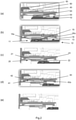
- an actuator 100 comprises a ball nut 10 provided on a ball screw shaft 70.
- the ball screw shaft 70 can be rotated by input torque transmission 90 via face gears 92 and bearings 94.
- the bearings 94 support the radial and axial loads and maintain the torque transmission.
- a ring nut 75 is attached to a distal end of the ball nut 10.
- the ring nut 75 retains a deployment tube 80 which is attached to a TRAS moving element (thrust reverser surface 200, shown in Figure 8 ).
- TRAS moving element thrust reverser surface 200, shown in Figure 8 .
- a locking arrangement for the actuator 100 which acts to lock the ball nut 10 in a stowed (locked) position, comprises a lock housing 20, a plurality of locking elements 30 (in this case, three), a locking collar 40, and a locking projection 15 on the ball nut 10.
- a proximity sensor 5 is configured to detect the actuator lock status.
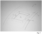
- the lock housing 20 (best shown in Figure 7 ) comprises a sleeve 21 with a plurality of apertures 23 (i.e. through holes). These are best shown in Figures 4 and 5 . Within each aperture is provided a respective locking element 30. The locking elements 30 are able to move radially outwards and inwards through the respective apertures 23.
- apertures 23 and corresponding locking elements 30 Whilst a plurality of apertures 23 and corresponding locking elements 30 are generally provided (in this case, three), for clarity, a single aperture 23 and locking element 30 are described below.
- a slot 22 running through the sleeve 21, along the axial length of the sleeve 21. That is, the slot 22 opens into the aperture, from both the distal and proximal sides of the aperture.
- the slot 22 receives a split pin 32 which also passes through a slit in the locking element 30.
- the locking element 30 is therefore able to move through the aperture 23 (in an outward radial direction, or an inward radial direction) and can be retained within the aperture 23 by the split pin 32, which is held within the slot 22 of the lock housing 21.
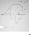
- the locking element 30 (best shown in Figure 6 ) is configured to engage with a locking projection 15 of the ball nut 10 (the locking projection 15 being provided at a proximal end 11 of the ball nut 10) in order to lock the ball nut 10 in a stowed position.
- On the distal side of the locking projection 15 (towards a distal end 12 of the ball nut 10) is a recessed portion 16 of the ball nut 10, which the locking element 30 sits in when the ball nut 10 is in the stowed position.
- the locking collar 40 Radially outward of the lock housing 20 is a locking collar 40.
- the locking collar 40 comprises a recessed portion 42 which the locking element 30 can rise into to allow for disengagement of the locking element 30 from the locking projection 15 on the ball nut 10.
- the locking collar 40 is movable under the influence of a solenoid 50, and first, second and third springs 60, 62 and 64.
- the solenoid 50 and first and third springs 60 and 64 are configured to move the locking collar 40 towards the distal end (to the right, as shown in Figures 2 and 3 ), and the second spring 62 is configured to move the locking collar 40 towards the proximal end (to the left, as shown in Figures 2 and 3 ).
- Figures 2(a) to 2(e) show the movement of the ball nut 10 from a stowed (and locked) position - see Figure 2(a) - to an unlocked position - see Figure 2(e) .
- the ball nut 10 is in a locked position.
- the locking element 30 is engaged with the locking projection 15 of the ball nut 10 such that movement of the ball nut 10 in the distal direction (to the right, as shown in the Figure) is not possible.
- the locking projection 15 on the ball nut 10 defines at least partially a recessed portion 16 of the ball nut 10 and the locking element 30 sits in the recessed portion 16 of the ball nut 10 when the ball nut 10 is in the stowed position.
- the locking element 30 is sandwiched (i.e. a compressive force is applied to the locking element 30) between the inner periphery 41 of the locking collar 40, and the recessed portion 16 of the ball nut 10 (which is on the outer periphery 13 of the ball nut 10).
- the alignment of the two recessed portions 16, 42 allows the locking element 30 to move radially outwards, riding along a chamfer 16a of the recessed portion 16 of the ball nut 10 (i.e. the distal side of the locking projection).
- the locking element 30 has a corresponding (i.e. complementary) chamfered surface 30c, such that the two chamfered surfaces ride over one another to allow smooth movement of the locking element 30 radially outwards (i.e. upwards, as shown in the Figure). Whilst the locking collar 40 and ball nut 10 are able to move relative to the actuator housing 150, the lock housing 20 is fixed.
- movement of the locking collar 40 towards the distal end of the ball nut 10 is driven by a solenoid 50, and a restorative force in the opposite direction (i.e. towards the proximal end of the ball screw) is provided by the first and third springs 60 and 64.
- a hydraulic system may be provided to provide movement of the locking collar 40. In such a case, movement of the locking collar 40 may be caused by a piston.
- the actuator 100 may be mechanically connected to a thrust reverser surface 200 (for example, a clamshell, blocker door or translating cowl) of a thrust reverser actuation system 500, such that movement of the actuator 100 results in movement of the thrust reverser surface 200.
- the thrust reverser actuation system may be provided in a gas turbine engine, and particularly in a turbofan engine, for example in an aircraft.
Landscapes
- Engineering & Computer Science (AREA)
- General Engineering & Computer Science (AREA)
- Mechanical Engineering (AREA)
- Chemical & Material Sciences (AREA)
- Combustion & Propulsion (AREA)
- Transmission Devices (AREA)
Claims (12)
- Aktuator (100), der Folgendes umfasst:eine Kugelgewindemutter (10);ein Verriegelungsgehäuse (20), das radial außerhalb der Kugelgewindemutter angeordnet ist und ein proximales Ende der Kugelgewindemutter überlappt, wenn sich die Kugelgewindemutter in einer verstauten Position befindet, wobei das Verriegelungsgehäuse eine Hülse (21) umfasst, in der sich eine Öffnung (23) befindet, und wobei ein Verriegelungselement (30) innerhalb der Öffnung zurückgehalten ist und sich in einer radialen Richtung durch die Öffnung bewegen kann;einen Verriegelungsbund (40), der radial außerhalb des Verriegelungsgehäuses (20) angeordnet ist und das Verriegelungsgehäuse überlappt, wobei sich das Verriegelungselement (30) zwischen einem Innenumfang des Verriegelungsbunds und einem Außenumfang der Kugelgewindemutter (10) erstreckt, wenn sich die Kugelgewindemutter in der verstauten Position befindet,wobei das Verriegelungselement in einen Verriegelungsvorsprung (15) an der Kugelgewindemutter eingreift, wenn sich die Kugelgewindemutter in der verstauten Position befindet, um die Kugelgewindemutter in der verstauten Position zurückzuhalten, und wobei der Verriegelungsbund (40) angeordnet ist, um sich in Richtung eines distalen Endes der Kugelgewindemutter (10) zu bewegen, um einen vertieften Abschnitt des Verriegelungsbunds mit dem Verriegelungselement (30) auszurichten, um zu ermöglichen, dass das Verriegelungselement über den Verriegelungsvorsprung (15) der Kugelgewindemutter hochrutscht, wodurch das Verriegelungselement von dem Verriegelungsvorsprung an der Kugelgewindemutter gelöst wird, was eine Bewegung der Kugelgewindemutter ermöglicht,und wobei der Aktuator ferner in Solenoid (50), das die Bewegung des Verriegelungsbunds (40) antreibt, oder ein hydraulisches System, das die Bewegung des Verriegelungsbunds antreibt, umfasst.
- Aktuator nach Anspruch 1, wobei der Verriegelungsvorsprung (15) an der Kugelgewindemutter gefast ist und die Oberflächen des Verriegelungselements (30), die in den Verriegelungsvorsprung an der Kugelgewindemutter eingreifen, eine entsprechende Fase aufweisen.
- Aktuator nach Anspruch 1 oder 2, wobei das Verriegelungsgehäuse (20) an einem Gehäuse des Aktuators verankert ist und sich relativ zu diesem nicht bewegt, und/oder wobei die Kugelgewindemutter (10) dazu konfiguriert ist, sich relativ zu dem Verriegelungsgehäuse zu bewegen.
- Aktuator nach einem der vorstehenden Ansprüche, wobei eine Seite des vertieften Abschnitts des Verriegelungsbunds (40) gefast ist und die Oberfläche des Verriegelungselements (30), das in die Seite des vertieften Abschnitts des Verriegelungsbunds eingreift, eine entsprechende Fase aufweist.
- Aktuator nach einem der vorstehenden Ansprüche, wobei die Erstreckung des Verriegelungselements (30) in der radialen Richtung gleich dem Abstand zwischen dem Außenumfang der Kugelgewindemutter (10) und dem Innenumfang des Verriegelungsbunds (40) ist.
- Aktuator nach einem der vorstehenden Ansprüche, wobei das Solenoid deaktiviert ist, wenn sich die Kugelgewindemutter (10) in der verstauten Position befindet.
- Aktuator nach einem der vorstehenden Ansprüche, umfassend eine Feder (62), die eine Rückstellkraft bereitstellt, um den Verriegelungsbund (40) in eine Verriegelungsposition zurückzuführen.
- Aktuator nach einem der vorstehenden Ansprüche, wobei das Verriegelungselement (30) einen Schlitz umfasst, in dem ein Sicherungsstift (32) bereitgestellt ist, der angeordnet ist, um das Verriegelungselement innerhalb des Verriegelungsgehäuses zurückzuhalten, wenn sich die Kugelgewindemutter (10) in einer gelösten Position befindet.
- Aktuator nach einem der vorstehenden Ansprüche, wobei die Kugelspindel an einem Kugelspindelschaft (70) bereitgestellt ist.
- Aktuator nach einem der vorstehenden Ansprüche, umfassend eine Vielzahl von Verriegelungselementen (30), optional 2 bis 4 Verriegelungselemente, optional 3 Verriegelungselemente, und eine entsprechende Vielzahl von Öffnungen (23) in dem Verriegelungsgehäuse.
- Schubumkehrer-Betätigungssystem, das den Aktuator nach einem der vorstehenden Ansprüche umfasst, wobei der Aktuator dazu konfiguriert ist, einen Abschnitt des Schubumkehrersystems zu bewegen.
- Verfahren zum Verriegeln und Entriegeln eines Aktuators (100) in einer verstauten Position, wobei der Aktuator Folgendes umfasst:eine Kugelgewindemutter (10), die entlang einer Achse bewegbar ist;ein Verriegelungsgehäuse (20), das radial außerhalb der Kugelgewindemutter angeordnet ist und ein proximales Ende der Kugelgewindemutter überlappt, wenn sich die Kugelgewindemutter in einer verstauten Position befindet, wobei das Verriegelungsgehäuse eine Hülse (21) umfasst, in der sich eine Öffnung (23) befindet;ein Verriegelungselement (30), das innerhalb der Öffnung zurückgehalten wird und sich in einer radialen Richtung durch die Öffnung bewegen kann;einen Verriegelungsbund (40), der radial außerhalb des Verriegelungsgehäuses (20) angeordnet ist und das Verriegelungsgehäuse überlappt, wobei sich das Verriegelungselement (30) zwischen einem Innenumfang des Verriegelungsbunds und einem Außenumfang der Kugelgewindemutter (10) erstreckt, wenn sich die Kugelgewindemutter in der verstauten Position befindet,wobei das Verfahren Folgendes umfasst:Eingreifen des Verriegelungselements in einen Verriegelungsvorsprung (15) an der Kugelgewindemutter, wenn sich die Kugelgewindemutter in der verstauten Position befindet, wodurch die Kugelgewindemutter in der verstauten Position zurückgehalten wird,und Antreiben des Verriegelungsbunds unter Verwendung eines Solenoids (5) oder eines hydraulischen Systems, das eine Bewegung des Verriegelungsbunds (40) in Richtung eines distalen Endes der Kugelgewindemutter (10) antreibt, um einen vertieften Abschnitt des Verriegelungsbunds mit dem Verriegelungselement (30) auszurichten, um zu ermöglichen, dass das Verriegelungselement über den Verriegelungsvorsprung (15) der Kugelgewindemutter hochrutscht, wodurch das Verriegelungselement von dem Verriegelungsvorsprung an der Kugelgewindemutter gelöst wird, was eine Bewegung der Kugelgewindemutter ermöglicht.
Priority Applications (2)
| Application Number | Priority Date | Filing Date | Title |
|---|---|---|---|
| EP17172286.1A EP3406888B1 (de) | 2017-05-22 | 2017-05-22 | Aktuator |
| US15/984,598 US10823264B2 (en) | 2017-05-22 | 2018-05-21 | Actuator |
Applications Claiming Priority (1)
| Application Number | Priority Date | Filing Date | Title |
|---|---|---|---|
| EP17172286.1A EP3406888B1 (de) | 2017-05-22 | 2017-05-22 | Aktuator |
Publications (2)
| Publication Number | Publication Date |
|---|---|
| EP3406888A1 EP3406888A1 (de) | 2018-11-28 |
| EP3406888B1 true EP3406888B1 (de) | 2022-03-23 |
Family
ID=58765741
Family Applications (1)
| Application Number | Title | Priority Date | Filing Date |
|---|---|---|---|
| EP17172286.1A Active EP3406888B1 (de) | 2017-05-22 | 2017-05-22 | Aktuator |
Country Status (2)
| Country | Link |
|---|---|
| US (1) | US10823264B2 (de) |
| EP (1) | EP3406888B1 (de) |
Families Citing this family (7)
| Publication number | Priority date | Publication date | Assignee | Title |
|---|---|---|---|---|
| CN110192046B (zh) * | 2016-12-30 | 2022-05-27 | 赛峰电子与防务公司 | 带有被动锁定的致动器 |
| US10583917B2 (en) * | 2017-05-18 | 2020-03-10 | Goodrich Corporation | Electromechanical actuator disconnect |
| CN110466796B (zh) * | 2019-07-30 | 2023-02-28 | 中国航发沈阳发动机研究所 | 一种反推力装置手动展开收起装置 |
| US11512665B2 (en) | 2020-03-20 | 2022-11-29 | The Boeing Company | Locking linear actuator |
| US20220228654A1 (en) * | 2021-01-20 | 2022-07-21 | Eaton Intelligent Power Limited | Screw drive with self-locking mechanism |
| EP4039963B1 (de) * | 2021-02-09 | 2023-11-22 | Goodrich Actuation Systems Limited | Vorspannsystem für einen aktuator |
| US11788490B1 (en) | 2022-12-05 | 2023-10-17 | Woodward, Inc. | Traveling finger lock for an actuator |
Family Cites Families (12)
| Publication number | Priority date | Publication date | Assignee | Title |
|---|---|---|---|---|
| DE50209973D1 (de) * | 2001-03-28 | 2007-05-31 | Continental Teves Ag & Co Ohg | Walzkörpergewindetrieb und antriebseinrichtung eines kraftfahrzeug-achslenkmoduls |
| US6935097B2 (en) | 2003-04-17 | 2005-08-30 | Honeywell International, Inc. | Lock assembly that inhibits thrust reverser movement at or near the stowed position |
| US7216581B2 (en) | 2004-01-16 | 2007-05-15 | The Boeing Company | Piston locking actuator |
| GB0604520D0 (en) * | 2006-03-07 | 2006-04-12 | Smiths Group Plc | Actuators |
| GB0817775D0 (en) | 2008-09-29 | 2008-11-05 | Goodrich Actuation Systems Ltd | Actuator |
| US8499653B1 (en) | 2009-06-18 | 2013-08-06 | The Boeing Company | Fault tolerant electro-mechanical actuator |
| US8715132B2 (en) | 2010-12-31 | 2014-05-06 | Woodward Hrt, Inc. | Linear actuator and method of operation thereof |
| US9188081B2 (en) | 2012-04-10 | 2015-11-17 | Honeywell International Inc. | Thrust reverser actuator with primary lock |
| FR3006379B1 (fr) * | 2013-06-04 | 2015-06-19 | Sagem Defense Securite | Dispositif d'actionnement pour deplacer un capot mobile d'un inverseur de poussee |
| FR3008741B1 (fr) | 2013-07-17 | 2017-04-28 | Aircelle Sa | Systeme inverseur de poussee electrique pour nacelle de moteur d'aeronef et nacelle de moteur d'aeronef ainsi equipee |
| US9857827B2 (en) | 2014-03-04 | 2018-01-02 | The Boeing Company | Locking system for an actuator device |
| EP3119969B1 (de) * | 2014-03-19 | 2020-08-12 | Marathonnorco Aerospace, Inc. | Stabverriegelungsmechanismus zum ziehen, anheben und offenhalten |
-
2017
- 2017-05-22 EP EP17172286.1A patent/EP3406888B1/de active Active
-
2018
- 2018-05-21 US US15/984,598 patent/US10823264B2/en active Active
Also Published As
| Publication number | Publication date |
|---|---|
| US10823264B2 (en) | 2020-11-03 |
| EP3406888A1 (de) | 2018-11-28 |
| US20180335115A1 (en) | 2018-11-22 |
Similar Documents
| Publication | Publication Date | Title |
|---|---|---|
| EP3406888B1 (de) | Aktuator | |
| EP2617978B1 (de) | Integrierter Schubumkehraktuator und Aktuator für eine im Querschnitt verstellbare Schubdüse | |
| US9493230B2 (en) | Drive assembly with selective disconnect | |
| EP3489497B1 (de) | Flugzeug mit schubdüsenantriebssystem zur sperrung der schubumkehrvorrichtung sowie verfahren zum betrieb | |
| EP3017170B1 (de) | Motor und bandklammer | |
| US9353804B2 (en) | Harmonic drive assembly with selective disconnect and method | |
| EP3301326B1 (de) | Linearaktuator mit montagestruktur mit mehreren freiheitsgraden | |
| EP3931434B1 (de) | Verfahrbares fingerschloss für einen aktuator | |
| CN110366650B (zh) | 带有集成的锁定的气缸 | |
| US20040112040A1 (en) | Thrust reverser system power drive unit with dual sequential torque decoupler and method | |
| JP6110994B2 (ja) | スラストリバーサロックアウト機構を有するエンジン | |
| EP2865878B1 (de) | Kardanisch aufgehängter Stift für Strahlantriebssystem | |
| US7441642B2 (en) | Low inertia ball brake/clutch | |
| US11788490B1 (en) | Traveling finger lock for an actuator | |
| EP3404245B1 (de) | Tertiäres sperrsystem für eine schubumkehrvorrichtung | |
| US20240183325A1 (en) | Traveling finger lock for an actuator | |
| EP3406859B1 (de) | Tertiäres sperrsystem für schubumkehrer | |
| WO2015065428A1 (en) | Thrust reverser system and engine assembly with lockout mechanism |
Legal Events
| Date | Code | Title | Description |
|---|---|---|---|
| PUAI | Public reference made under article 153(3) epc to a published international application that has entered the european phase |
Free format text: ORIGINAL CODE: 0009012 |
|
| STAA | Information on the status of an ep patent application or granted ep patent |
Free format text: STATUS: THE APPLICATION HAS BEEN PUBLISHED |
|
| AK | Designated contracting states |
Kind code of ref document: A1 Designated state(s): AL AT BE BG CH CY CZ DE DK EE ES FI FR GB GR HR HU IE IS IT LI LT LU LV MC MK MT NL NO PL PT RO RS SE SI SK SM TR |
|
| AX | Request for extension of the european patent |
Extension state: BA ME |
|
| STAA | Information on the status of an ep patent application or granted ep patent |
Free format text: STATUS: REQUEST FOR EXAMINATION WAS MADE |
|
| 17P | Request for examination filed |
Effective date: 20190528 |
|
| RBV | Designated contracting states (corrected) |
Designated state(s): AL AT BE BG CH CY CZ DE DK EE ES FI FR GB GR HR HU IE IS IT LI LT LU LV MC MK MT NL NO PL PT RO RS SE SI SK SM TR |
|
| GRAP | Despatch of communication of intention to grant a patent |
Free format text: ORIGINAL CODE: EPIDOSNIGR1 |
|
| STAA | Information on the status of an ep patent application or granted ep patent |
Free format text: STATUS: GRANT OF PATENT IS INTENDED |
|
| RIC1 | Information provided on ipc code assigned before grant |
Ipc: F16H 25/24 20060101ALI20210921BHEP Ipc: F02K 1/76 20060101AFI20210921BHEP |
|
| INTG | Intention to grant announced |
Effective date: 20211005 |
|
| GRAS | Grant fee paid |
Free format text: ORIGINAL CODE: EPIDOSNIGR3 |
|
| GRAA | (expected) grant |
Free format text: ORIGINAL CODE: 0009210 |
|
| STAA | Information on the status of an ep patent application or granted ep patent |
Free format text: STATUS: THE PATENT HAS BEEN GRANTED |
|
| AK | Designated contracting states |
Kind code of ref document: B1 Designated state(s): AL AT BE BG CH CY CZ DE DK EE ES FI FR GB GR HR HU IE IS IT LI LT LU LV MC MK MT NL NO PL PT RO RS SE SI SK SM TR |
|
| REG | Reference to a national code |
Ref country code: GB Ref legal event code: FG4D |
|
| REG | Reference to a national code |
Ref country code: CH Ref legal event code: EP |
|
| REG | Reference to a national code |
Ref country code: IE Ref legal event code: FG4D |
|
| REG | Reference to a national code |
Ref country code: DE Ref legal event code: R096 Ref document number: 602017054849 Country of ref document: DE |
|
| REG | Reference to a national code |
Ref country code: AT Ref legal event code: REF Ref document number: 1477587 Country of ref document: AT Kind code of ref document: T Effective date: 20220415 |
|
| REG | Reference to a national code |
Ref country code: LT Ref legal event code: MG9D |
|
| REG | Reference to a national code |
Ref country code: NL Ref legal event code: MP Effective date: 20220323 |
|
| PG25 | Lapsed in a contracting state [announced via postgrant information from national office to epo] |
Ref country code: SE Free format text: LAPSE BECAUSE OF FAILURE TO SUBMIT A TRANSLATION OF THE DESCRIPTION OR TO PAY THE FEE WITHIN THE PRESCRIBED TIME-LIMIT Effective date: 20220323 Ref country code: RS Free format text: LAPSE BECAUSE OF FAILURE TO SUBMIT A TRANSLATION OF THE DESCRIPTION OR TO PAY THE FEE WITHIN THE PRESCRIBED TIME-LIMIT Effective date: 20220323 Ref country code: NO Free format text: LAPSE BECAUSE OF FAILURE TO SUBMIT A TRANSLATION OF THE DESCRIPTION OR TO PAY THE FEE WITHIN THE PRESCRIBED TIME-LIMIT Effective date: 20220623 Ref country code: LT Free format text: LAPSE BECAUSE OF FAILURE TO SUBMIT A TRANSLATION OF THE DESCRIPTION OR TO PAY THE FEE WITHIN THE PRESCRIBED TIME-LIMIT Effective date: 20220323 Ref country code: HR Free format text: LAPSE BECAUSE OF FAILURE TO SUBMIT A TRANSLATION OF THE DESCRIPTION OR TO PAY THE FEE WITHIN THE PRESCRIBED TIME-LIMIT Effective date: 20220323 Ref country code: BG Free format text: LAPSE BECAUSE OF FAILURE TO SUBMIT A TRANSLATION OF THE DESCRIPTION OR TO PAY THE FEE WITHIN THE PRESCRIBED TIME-LIMIT Effective date: 20220623 |
|
| REG | Reference to a national code |
Ref country code: AT Ref legal event code: MK05 Ref document number: 1477587 Country of ref document: AT Kind code of ref document: T Effective date: 20220323 |
|
| PG25 | Lapsed in a contracting state [announced via postgrant information from national office to epo] |
Ref country code: LV Free format text: LAPSE BECAUSE OF FAILURE TO SUBMIT A TRANSLATION OF THE DESCRIPTION OR TO PAY THE FEE WITHIN THE PRESCRIBED TIME-LIMIT Effective date: 20220323 Ref country code: GR Free format text: LAPSE BECAUSE OF FAILURE TO SUBMIT A TRANSLATION OF THE DESCRIPTION OR TO PAY THE FEE WITHIN THE PRESCRIBED TIME-LIMIT Effective date: 20220624 Ref country code: FI Free format text: LAPSE BECAUSE OF FAILURE TO SUBMIT A TRANSLATION OF THE DESCRIPTION OR TO PAY THE FEE WITHIN THE PRESCRIBED TIME-LIMIT Effective date: 20220323 |
|
| PG25 | Lapsed in a contracting state [announced via postgrant information from national office to epo] |
Ref country code: NL Free format text: LAPSE BECAUSE OF FAILURE TO SUBMIT A TRANSLATION OF THE DESCRIPTION OR TO PAY THE FEE WITHIN THE PRESCRIBED TIME-LIMIT Effective date: 20220323 |
|
| PG25 | Lapsed in a contracting state [announced via postgrant information from national office to epo] |
Ref country code: SM Free format text: LAPSE BECAUSE OF FAILURE TO SUBMIT A TRANSLATION OF THE DESCRIPTION OR TO PAY THE FEE WITHIN THE PRESCRIBED TIME-LIMIT Effective date: 20220323 Ref country code: SK Free format text: LAPSE BECAUSE OF FAILURE TO SUBMIT A TRANSLATION OF THE DESCRIPTION OR TO PAY THE FEE WITHIN THE PRESCRIBED TIME-LIMIT Effective date: 20220323 Ref country code: RO Free format text: LAPSE BECAUSE OF FAILURE TO SUBMIT A TRANSLATION OF THE DESCRIPTION OR TO PAY THE FEE WITHIN THE PRESCRIBED TIME-LIMIT Effective date: 20220323 Ref country code: PT Free format text: LAPSE BECAUSE OF FAILURE TO SUBMIT A TRANSLATION OF THE DESCRIPTION OR TO PAY THE FEE WITHIN THE PRESCRIBED TIME-LIMIT Effective date: 20220725 Ref country code: ES Free format text: LAPSE BECAUSE OF FAILURE TO SUBMIT A TRANSLATION OF THE DESCRIPTION OR TO PAY THE FEE WITHIN THE PRESCRIBED TIME-LIMIT Effective date: 20220323 Ref country code: EE Free format text: LAPSE BECAUSE OF FAILURE TO SUBMIT A TRANSLATION OF THE DESCRIPTION OR TO PAY THE FEE WITHIN THE PRESCRIBED TIME-LIMIT Effective date: 20220323 Ref country code: CZ Free format text: LAPSE BECAUSE OF FAILURE TO SUBMIT A TRANSLATION OF THE DESCRIPTION OR TO PAY THE FEE WITHIN THE PRESCRIBED TIME-LIMIT Effective date: 20220323 Ref country code: AT Free format text: LAPSE BECAUSE OF FAILURE TO SUBMIT A TRANSLATION OF THE DESCRIPTION OR TO PAY THE FEE WITHIN THE PRESCRIBED TIME-LIMIT Effective date: 20220323 |
|
| PG25 | Lapsed in a contracting state [announced via postgrant information from national office to epo] |
Ref country code: PL Free format text: LAPSE BECAUSE OF FAILURE TO SUBMIT A TRANSLATION OF THE DESCRIPTION OR TO PAY THE FEE WITHIN THE PRESCRIBED TIME-LIMIT Effective date: 20220323 Ref country code: IS Free format text: LAPSE BECAUSE OF FAILURE TO SUBMIT A TRANSLATION OF THE DESCRIPTION OR TO PAY THE FEE WITHIN THE PRESCRIBED TIME-LIMIT Effective date: 20220723 Ref country code: AL Free format text: LAPSE BECAUSE OF FAILURE TO SUBMIT A TRANSLATION OF THE DESCRIPTION OR TO PAY THE FEE WITHIN THE PRESCRIBED TIME-LIMIT Effective date: 20220323 |
|
| REG | Reference to a national code |
Ref country code: CH Ref legal event code: PL |
|
| REG | Reference to a national code |
Ref country code: DE Ref legal event code: R097 Ref document number: 602017054849 Country of ref document: DE |
|
| REG | Reference to a national code |
Ref country code: BE Ref legal event code: MM Effective date: 20220531 |
|
| PLBE | No opposition filed within time limit |
Free format text: ORIGINAL CODE: 0009261 |
|
| STAA | Information on the status of an ep patent application or granted ep patent |
Free format text: STATUS: NO OPPOSITION FILED WITHIN TIME LIMIT |
|
| PG25 | Lapsed in a contracting state [announced via postgrant information from national office to epo] |
Ref country code: MC Free format text: LAPSE BECAUSE OF FAILURE TO SUBMIT A TRANSLATION OF THE DESCRIPTION OR TO PAY THE FEE WITHIN THE PRESCRIBED TIME-LIMIT Effective date: 20220323 Ref country code: LU Free format text: LAPSE BECAUSE OF NON-PAYMENT OF DUE FEES Effective date: 20220522 Ref country code: LI Free format text: LAPSE BECAUSE OF NON-PAYMENT OF DUE FEES Effective date: 20220531 Ref country code: DK Free format text: LAPSE BECAUSE OF FAILURE TO SUBMIT A TRANSLATION OF THE DESCRIPTION OR TO PAY THE FEE WITHIN THE PRESCRIBED TIME-LIMIT Effective date: 20220323 Ref country code: CH Free format text: LAPSE BECAUSE OF NON-PAYMENT OF DUE FEES Effective date: 20220531 |
|
| 26N | No opposition filed |
Effective date: 20230102 |
|
| PG25 | Lapsed in a contracting state [announced via postgrant information from national office to epo] |
Ref country code: IE Free format text: LAPSE BECAUSE OF NON-PAYMENT OF DUE FEES Effective date: 20220522 |
|
| PG25 | Lapsed in a contracting state [announced via postgrant information from national office to epo] |
Ref country code: SI Free format text: LAPSE BECAUSE OF FAILURE TO SUBMIT A TRANSLATION OF THE DESCRIPTION OR TO PAY THE FEE WITHIN THE PRESCRIBED TIME-LIMIT Effective date: 20220323 Ref country code: BE Free format text: LAPSE BECAUSE OF NON-PAYMENT OF DUE FEES Effective date: 20220531 |
|
| PGFP | Annual fee paid to national office [announced via postgrant information from national office to epo] |
Ref country code: IT Payment date: 20230420 Year of fee payment: 7 Ref country code: FR Payment date: 20230420 Year of fee payment: 7 Ref country code: DE Payment date: 20230419 Year of fee payment: 7 |
|
| P01 | Opt-out of the competence of the unified patent court (upc) registered |
Effective date: 20230706 |
|
| PGFP | Annual fee paid to national office [announced via postgrant information from national office to epo] |
Ref country code: GB Payment date: 20230420 Year of fee payment: 7 |
|
| PG25 | Lapsed in a contracting state [announced via postgrant information from national office to epo] |
Ref country code: HU Free format text: LAPSE BECAUSE OF FAILURE TO SUBMIT A TRANSLATION OF THE DESCRIPTION OR TO PAY THE FEE WITHIN THE PRESCRIBED TIME-LIMIT; INVALID AB INITIO Effective date: 20170522 |
|
| PG25 | Lapsed in a contracting state [announced via postgrant information from national office to epo] |
Ref country code: MK Free format text: LAPSE BECAUSE OF FAILURE TO SUBMIT A TRANSLATION OF THE DESCRIPTION OR TO PAY THE FEE WITHIN THE PRESCRIBED TIME-LIMIT Effective date: 20220323 Ref country code: CY Free format text: LAPSE BECAUSE OF FAILURE TO SUBMIT A TRANSLATION OF THE DESCRIPTION OR TO PAY THE FEE WITHIN THE PRESCRIBED TIME-LIMIT Effective date: 20220323 |