EP3406872A1 - Micro coil - Google Patents
Micro coil Download PDFInfo
- Publication number
- EP3406872A1 EP3406872A1 EP18172704.1A EP18172704A EP3406872A1 EP 3406872 A1 EP3406872 A1 EP 3406872A1 EP 18172704 A EP18172704 A EP 18172704A EP 3406872 A1 EP3406872 A1 EP 3406872A1
- Authority
- EP
- European Patent Office
- Prior art keywords
- micro coil
- coating layer
- micro
- coil body
- temperature environment
- Prior art date
- Legal status (The legal status is an assumption and is not a legal conclusion. Google has not performed a legal analysis and makes no representation as to the accuracy of the status listed.)
- Granted
Links
Images

Classifications
-
- B—PERFORMING OPERATIONS; TRANSPORTING
- B01—PHYSICAL OR CHEMICAL PROCESSES OR APPARATUS IN GENERAL
- B01J—CHEMICAL OR PHYSICAL PROCESSES, e.g. CATALYSIS OR COLLOID CHEMISTRY; THEIR RELEVANT APPARATUS
- B01J23/00—Catalysts comprising metals or metal oxides or hydroxides, not provided for in group B01J21/00
- B01J23/38—Catalysts comprising metals or metal oxides or hydroxides, not provided for in group B01J21/00 of noble metals
- B01J23/48—Silver or gold
- B01J23/50—Silver
-
- H—ELECTRICITY
- H05—ELECTRIC TECHNIQUES NOT OTHERWISE PROVIDED FOR
- H05B—ELECTRIC HEATING; ELECTRIC LIGHT SOURCES NOT OTHERWISE PROVIDED FOR; CIRCUIT ARRANGEMENTS FOR ELECTRIC LIGHT SOURCES, IN GENERAL
- H05B6/00—Heating by electric, magnetic or electromagnetic fields
- H05B6/02—Induction heating
- H05B6/36—Coil arrangements
-
- B—PERFORMING OPERATIONS; TRANSPORTING
- B01—PHYSICAL OR CHEMICAL PROCESSES OR APPARATUS IN GENERAL
- B01D—SEPARATION
- B01D53/00—Separation of gases or vapours; Recovering vapours of volatile solvents from gases; Chemical or biological purification of waste gases, e.g. engine exhaust gases, smoke, fumes, flue gases, aerosols
- B01D53/34—Chemical or biological purification of waste gases
- B01D53/92—Chemical or biological purification of waste gases of engine exhaust gases
- B01D53/94—Chemical or biological purification of waste gases of engine exhaust gases by catalytic processes
- B01D53/9404—Removing only nitrogen compounds
- B01D53/9409—Nitrogen oxides
- B01D53/9431—Processes characterised by a specific device
-
- B—PERFORMING OPERATIONS; TRANSPORTING
- B01—PHYSICAL OR CHEMICAL PROCESSES OR APPARATUS IN GENERAL
- B01J—CHEMICAL OR PHYSICAL PROCESSES, e.g. CATALYSIS OR COLLOID CHEMISTRY; THEIR RELEVANT APPARATUS
- B01J21/00—Catalysts comprising the elements, oxides, or hydroxides of magnesium, boron, aluminium, carbon, silicon, titanium, zirconium, or hafnium
- B01J21/06—Silicon, titanium, zirconium or hafnium; Oxides or hydroxides thereof
- B01J21/063—Titanium; Oxides or hydroxides thereof
-
- B—PERFORMING OPERATIONS; TRANSPORTING
- B01—PHYSICAL OR CHEMICAL PROCESSES OR APPARATUS IN GENERAL
- B01J—CHEMICAL OR PHYSICAL PROCESSES, e.g. CATALYSIS OR COLLOID CHEMISTRY; THEIR RELEVANT APPARATUS
- B01J21/00—Catalysts comprising the elements, oxides, or hydroxides of magnesium, boron, aluminium, carbon, silicon, titanium, zirconium, or hafnium
- B01J21/18—Carbon
-
- B—PERFORMING OPERATIONS; TRANSPORTING
- B01—PHYSICAL OR CHEMICAL PROCESSES OR APPARATUS IN GENERAL
- B01J—CHEMICAL OR PHYSICAL PROCESSES, e.g. CATALYSIS OR COLLOID CHEMISTRY; THEIR RELEVANT APPARATUS
- B01J23/00—Catalysts comprising metals or metal oxides or hydroxides, not provided for in group B01J21/00
- B01J23/002—Mixed oxides other than spinels, e.g. perovskite
-
- B—PERFORMING OPERATIONS; TRANSPORTING
- B01—PHYSICAL OR CHEMICAL PROCESSES OR APPARATUS IN GENERAL
- B01J—CHEMICAL OR PHYSICAL PROCESSES, e.g. CATALYSIS OR COLLOID CHEMISTRY; THEIR RELEVANT APPARATUS
- B01J27/00—Catalysts comprising the elements or compounds of halogens, sulfur, selenium, tellurium, phosphorus or nitrogen; Catalysts comprising carbon compounds
- B01J27/20—Carbon compounds
- B01J27/22—Carbides
-
- B—PERFORMING OPERATIONS; TRANSPORTING
- B01—PHYSICAL OR CHEMICAL PROCESSES OR APPARATUS IN GENERAL
- B01J—CHEMICAL OR PHYSICAL PROCESSES, e.g. CATALYSIS OR COLLOID CHEMISTRY; THEIR RELEVANT APPARATUS
- B01J27/00—Catalysts comprising the elements or compounds of halogens, sulfur, selenium, tellurium, phosphorus or nitrogen; Catalysts comprising carbon compounds
- B01J27/24—Nitrogen compounds
-
- B—PERFORMING OPERATIONS; TRANSPORTING
- B01—PHYSICAL OR CHEMICAL PROCESSES OR APPARATUS IN GENERAL
- B01J—CHEMICAL OR PHYSICAL PROCESSES, e.g. CATALYSIS OR COLLOID CHEMISTRY; THEIR RELEVANT APPARATUS
- B01J35/00—Catalysts, in general, characterised by their form or physical properties
- B01J35/30—Catalysts, in general, characterised by their form or physical properties characterised by their physical properties
- B01J35/33—Electric or magnetic properties
-
- B—PERFORMING OPERATIONS; TRANSPORTING
- B01—PHYSICAL OR CHEMICAL PROCESSES OR APPARATUS IN GENERAL
- B01J—CHEMICAL OR PHYSICAL PROCESSES, e.g. CATALYSIS OR COLLOID CHEMISTRY; THEIR RELEVANT APPARATUS
- B01J35/00—Catalysts, in general, characterised by their form or physical properties
- B01J35/70—Catalysts, in general, characterised by their form or physical properties characterised by their crystalline properties, e.g. semi-crystalline
- B01J35/733—Perovskite-type
-
- F—MECHANICAL ENGINEERING; LIGHTING; HEATING; WEAPONS; BLASTING
- F01—MACHINES OR ENGINES IN GENERAL; ENGINE PLANTS IN GENERAL; STEAM ENGINES
- F01N—GAS-FLOW SILENCERS OR EXHAUST APPARATUS FOR MACHINES OR ENGINES IN GENERAL; GAS-FLOW SILENCERS OR EXHAUST APPARATUS FOR INTERNAL-COMBUSTION ENGINES
- F01N3/00—Exhaust or silencing apparatus having means for purifying, rendering innocuous, or otherwise treating exhaust
- F01N3/08—Exhaust or silencing apparatus having means for purifying, rendering innocuous, or otherwise treating exhaust for rendering innocuous
- F01N3/10—Exhaust or silencing apparatus having means for purifying, rendering innocuous, or otherwise treating exhaust for rendering innocuous by thermal or catalytic conversion of noxious components of exhaust
- F01N3/18—Exhaust or silencing apparatus having means for purifying, rendering innocuous, or otherwise treating exhaust for rendering innocuous by thermal or catalytic conversion of noxious components of exhaust characterised by methods of operation; Control
- F01N3/20—Exhaust or silencing apparatus having means for purifying, rendering innocuous, or otherwise treating exhaust for rendering innocuous by thermal or catalytic conversion of noxious components of exhaust characterised by methods of operation; Control specially adapted for catalytic conversion
- F01N3/2006—Periodically heating or cooling catalytic reactors, e.g. at cold starting or overheating
- F01N3/2013—Periodically heating or cooling catalytic reactors, e.g. at cold starting or overheating using electric or magnetic heating means
-
- F—MECHANICAL ENGINEERING; LIGHTING; HEATING; WEAPONS; BLASTING
- F01—MACHINES OR ENGINES IN GENERAL; ENGINE PLANTS IN GENERAL; STEAM ENGINES
- F01N—GAS-FLOW SILENCERS OR EXHAUST APPARATUS FOR MACHINES OR ENGINES IN GENERAL; GAS-FLOW SILENCERS OR EXHAUST APPARATUS FOR INTERNAL-COMBUSTION ENGINES
- F01N3/00—Exhaust or silencing apparatus having means for purifying, rendering innocuous, or otherwise treating exhaust
- F01N3/08—Exhaust or silencing apparatus having means for purifying, rendering innocuous, or otherwise treating exhaust for rendering innocuous
- F01N3/10—Exhaust or silencing apparatus having means for purifying, rendering innocuous, or otherwise treating exhaust for rendering innocuous by thermal or catalytic conversion of noxious components of exhaust
- F01N3/18—Exhaust or silencing apparatus having means for purifying, rendering innocuous, or otherwise treating exhaust for rendering innocuous by thermal or catalytic conversion of noxious components of exhaust characterised by methods of operation; Control
- F01N3/20—Exhaust or silencing apparatus having means for purifying, rendering innocuous, or otherwise treating exhaust for rendering innocuous by thermal or catalytic conversion of noxious components of exhaust characterised by methods of operation; Control specially adapted for catalytic conversion
- F01N3/2006—Periodically heating or cooling catalytic reactors, e.g. at cold starting or overheating
- F01N3/2013—Periodically heating or cooling catalytic reactors, e.g. at cold starting or overheating using electric or magnetic heating means
- F01N3/202—Periodically heating or cooling catalytic reactors, e.g. at cold starting or overheating using electric or magnetic heating means using microwaves
-
- H—ELECTRICITY
- H01—ELECTRIC ELEMENTS
- H01B—CABLES; CONDUCTORS; INSULATORS; SELECTION OF MATERIALS FOR THEIR CONDUCTIVE, INSULATING OR DIELECTRIC PROPERTIES
- H01B1/00—Conductors or conductive bodies characterised by the conductive materials; Selection of materials as conductors
- H01B1/02—Conductors or conductive bodies characterised by the conductive materials; Selection of materials as conductors mainly consisting of metals or alloys
-
- H—ELECTRICITY
- H01—ELECTRIC ELEMENTS
- H01B—CABLES; CONDUCTORS; INSULATORS; SELECTION OF MATERIALS FOR THEIR CONDUCTIVE, INSULATING OR DIELECTRIC PROPERTIES
- H01B1/00—Conductors or conductive bodies characterised by the conductive materials; Selection of materials as conductors
- H01B1/04—Conductors or conductive bodies characterised by the conductive materials; Selection of materials as conductors mainly consisting of carbon-silicon compounds, carbon or silicon
-
- H—ELECTRICITY
- H01—ELECTRIC ELEMENTS
- H01B—CABLES; CONDUCTORS; INSULATORS; SELECTION OF MATERIALS FOR THEIR CONDUCTIVE, INSULATING OR DIELECTRIC PROPERTIES
- H01B1/00—Conductors or conductive bodies characterised by the conductive materials; Selection of materials as conductors
- H01B1/06—Conductors or conductive bodies characterised by the conductive materials; Selection of materials as conductors mainly consisting of other non-metallic substances
- H01B1/08—Conductors or conductive bodies characterised by the conductive materials; Selection of materials as conductors mainly consisting of other non-metallic substances oxides
-
- H—ELECTRICITY
- H01—ELECTRIC ELEMENTS
- H01B—CABLES; CONDUCTORS; INSULATORS; SELECTION OF MATERIALS FOR THEIR CONDUCTIVE, INSULATING OR DIELECTRIC PROPERTIES
- H01B7/00—Insulated conductors or cables characterised by their form
- H01B7/17—Protection against damage caused by external factors, e.g. sheaths or armouring
- H01B7/29—Protection against damage caused by extremes of temperature or by flame
- H01B7/292—Protection against damage caused by extremes of temperature or by flame using material resistant to heat
-
- B—PERFORMING OPERATIONS; TRANSPORTING
- B01—PHYSICAL OR CHEMICAL PROCESSES OR APPARATUS IN GENERAL
- B01D—SEPARATION
- B01D2255/00—Catalysts
- B01D2255/90—Physical characteristics of catalysts
-
- B—PERFORMING OPERATIONS; TRANSPORTING
- B01—PHYSICAL OR CHEMICAL PROCESSES OR APPARATUS IN GENERAL
- B01J—CHEMICAL OR PHYSICAL PROCESSES, e.g. CATALYSIS OR COLLOID CHEMISTRY; THEIR RELEVANT APPARATUS
- B01J35/00—Catalysts, in general, characterised by their form or physical properties
- B01J35/30—Catalysts, in general, characterised by their form or physical properties characterised by their physical properties
-
- F—MECHANICAL ENGINEERING; LIGHTING; HEATING; WEAPONS; BLASTING
- F01—MACHINES OR ENGINES IN GENERAL; ENGINE PLANTS IN GENERAL; STEAM ENGINES
- F01N—GAS-FLOW SILENCERS OR EXHAUST APPARATUS FOR MACHINES OR ENGINES IN GENERAL; GAS-FLOW SILENCERS OR EXHAUST APPARATUS FOR INTERNAL-COMBUSTION ENGINES
- F01N13/00—Exhaust or silencing apparatus characterised by constructional features
- F01N13/16—Selection of particular materials
-
- Y—GENERAL TAGGING OF NEW TECHNOLOGICAL DEVELOPMENTS; GENERAL TAGGING OF CROSS-SECTIONAL TECHNOLOGIES SPANNING OVER SEVERAL SECTIONS OF THE IPC; TECHNICAL SUBJECTS COVERED BY FORMER USPC CROSS-REFERENCE ART COLLECTIONS [XRACs] AND DIGESTS
- Y02—TECHNOLOGIES OR APPLICATIONS FOR MITIGATION OR ADAPTATION AGAINST CLIMATE CHANGE
- Y02T—CLIMATE CHANGE MITIGATION TECHNOLOGIES RELATED TO TRANSPORTATION
- Y02T10/00—Road transport of goods or passengers
- Y02T10/10—Internal combustion engine [ICE] based vehicles
- Y02T10/12—Improving ICE efficiencies
Definitions
- the invention relates to a micro coil that absorbs radio waves and generate heat.
- a radio wave absorber in a heat generating unit for heating an exhaust clean-up catalyst that cleans up exhaust gas of an internal combustion engine, and cause the radio wave absorber to generate heat by irradiating the radio wave absorber with microwaves, so that the generated heat is utilized for heating the exhaust clean-up catalyst.
- the radio wave absorber generates heat by converting energy of radio waves (microwaves) with which the absorber is irradiated, into thermal energy.
- conductive micro coils having electrical conductivity are known.
- a carbon micro coil composed of coil-shaped carbon fiber is known (see, for example, Japanese Patent Application Publication No. 2012-012736 ( JP 2012-012736 A )).
- a TiC micro coil composed of coil-shaped titanium carbide (TiC) is also known as one type of the conductive micro coils.
- the carbon micro coil is oxidized and gasified if it is used under a high-temperature environment (for example, at a temperature equal to or higher than 500°C) and an oxidizing atmosphere.
- a high-temperature environment for example, at a temperature equal to or higher than 500°C
- an oxidizing atmosphere is present in the exhaust clean-up catalyst. Accordingly, the carbon micro coil cannot be located as it is in the exhaust clean-up catalyst, for example, and cannot be used as a radio wave absorber for heating the catalyst.
- the TiC micro coil is used under a high-temperature environment and an oxidizing atmosphere, the coil is oxidized and changed into a TiO 2 micro coil, resulting in a loss of the conductivity and reduction of the radio wave absorbing capability.
- the TiC micro coil cannot also be located in the exhaust clean-up catalyst and used as the radio wave absorber for heating the catalyst. Accordingly, micro coils that function as a radio wave absorber, even under a high-temperature environment and an oxidizing atmosphere, have been desired.
- micro coil (which may also be referred to as "micro coil with a coating layer”) that functions as a radio wave absorber, even under a high-temperature environment and an oxidizing atmosphere
- a micro coil according to one aspect of the invention includes a micro coil body having heat resistance sufficient to keep the micro coil body from thermal decomposition and melting in a high-temperature environment, and a coating layer provided on a surface of the micro coil body.
- the coating layer has heat resistance, and has electrical conductivity under the high-temperature environment and an oxidizing atmosphere.
- the coating layer has a shape that causes induced current to be produced according to a magnetic-field component of radio waves, when the micro coil receives the radio waves.
- the coating layer having conductivity is formed on the surface of the micro coil body, in a shape that causes induced current to be produced according to a magnetic-field component of radio waves when the micro coil is irradiated with the radio waves. Therefore, when the micro coil with the coating layer is irradiated with radio waves (electromagnetic waves), such as microwaves, induced current is produced in the coating layer (in the micro coil body and the coating layer when the micro coil body also has conductivity), according to the magnetic-field component of the radio waves, and the induced current thus produced flows in the coating layer (the micro coil body and the coating layer when the micro coil body also has conductivity), to generate Joule heat. Accordingly, the micro coil with the coating layer can function as a radio wave absorber, even under the high-temperature environment and oxidizing atmosphere.
- the micro coil body has heat resistance
- the coating layer has heat resistance, and also has electrical conductivity even under a high-temperature environment and an oxidizing atmosphere. Therefore, even in the case where the micro coil with the coating layer is placed under the high-temperature environment and the oxidizing atmosphere, the coating layer can keep the above shape and conductivity. Accordingly, the micro coil with the coating layer can function as a radio wave absorber, even under the high-temperature environment and oxidizing atmosphere.
- the micro coil body may be one of a silicon nitride micro coil composed of silicon nitride, a titanium oxide micro coil composed of titanium oxide, and a titanium carbide micro coil composed of titanium carbide, and the coating layer may be configured to cover a part or an entire area of the surface of the micro coil body.
- the micro coil can function as a radio wave absorber, under a high-temperature environment and an oxidizing atmosphere, even if the micro coil body does not have electrical conductivity.
- the micro coil body may include a carbon micro coil composed of carbon, or a titanium carbide micro coil composed of titanium carbide, and the coating layer may be configured to cover an entire area of the surface of the micro coil body.
- the coating layer with which the entire area of the surface of the micro coil body is coated can prevent the carbon micro coil from being oxidized and gasified under a high-temperature environment and an oxidizing atmosphere.
- the coating layer can prevent the titanium carbide micro coil from being oxidized and losing conductivity under a high-temperature environment and an oxidizing atmosphere. Accordingly, when the micro coil with the coating layer is irradiated with radio waves, induced current is produced and flows in both the micro coil body (carbon micro coil or titanium carbide micro coil) and the coating layer, so that the Joule heat is generated. As a result, the micro coil with the coating layer can "convert energy of radio waves into thermal energy" with higher efficiency.
- the coating layer may contain at least one of conductive metals, conductive metal oxides, and conductive metal composite oxides.
- the coating layer is composed of at least one of the conductive metals, conductive metal oxides, and conductive metal composite oxides, which have the conductivity and are favorably used for the coating layer.
- the coating layer can function as a radio wave absorber, even under a high-temperature environment and an oxidizing atmosphere.
- the conductive metals may include one or more types of metal selected from platinum, gold, zinc, and silver
- the conductive metal oxides may include one or more types of metal oxide selected from silver oxide and zinc oxide
- the conductive metal composite oxides may include perovskite oxide.
- the coating layer is composed of a material or materials favorably used for the coating layer, and can function as a radio wave absorber, even under a high-temperature environment and an oxidizing atmosphere.
- the perovskite oxide may be selected from perovskite oxides having NOx removing capability.
- the coating layer is comprised of a perovskite oxide, which is favorably used for the coating layer, and also has NOx removing capability. Therefore, the coating layer can function as a radio wave absorber, even under a high-temperature environment and an oxidizing atmosphere, and can also function as a NOx removal catalyst.
- micro coil with a coating layer will be described referring to the drawings.
- the micro coil with the coating layer may be favorably used as a radio wave absorber included in a heating unit that heats an exhaust clean-up catalyst for cleaning up exhaust gas, in an emission control system of an internal combustion engine, for example.
- the heating unit generates heat when it is irradiated with microwaves.
- the micro coil with the coating layer has a micro coil body 10, and a coating layer 11 formed on a surface of the micro coil body 10.
- the micro coil body 10 has a coil shape (helical shape).
- the coil diameter of the micro coil body 10 is within a range of submicron to several dozens of microns, and its length (axial length) is within a range of several dozens of microns to several hundreds of microns, for example.
- the micro coil body 10 is a micro coil (which may be called "heat-resistant, insulating micro coil” when appropriate) having heat resistance and insulating capacity, and is composed of a coil-shaped material having heat resistance and insulating capacity.
- the "heat resistance” refers to “heat resistance sufficient to keep the micro coil body from thermal decomposition and melting in a high-temperature environment (an environment of temperatures equal to or higher 500°C and equal to or lower than 1000°C, for example)".
- the "insulating capacity” refers to "insulating capacity equivalent to the volume resistivity equal to or lager than 10 6 ⁇ cm”.
- the heat-resistant, insulating micro coil has the insulating capacity at ordinary temperatures.
- Examples of the heat-resistant, insulating material used for the micro coil body 10 include one or more types of insulating inorganic materials (namely, inorganic materials of which the volume resistivity is 10 6 ⁇ cm or larger at ordinary temperatures) selected from metal oxides (e.g., titanium oxide (TiO 2 )) and semimetal nitrides (e.g., silicon nitride (Si 3 N 4 )).
- metal oxides e.g., titanium oxide (TiO 2 )
- semimetal nitrides e.g., silicon nitride (Si 3 N 4 )
- a coil-shaped TiO 2 micro coil composed of titanium oxide (TiO 2 ), a coil-shaped Si 3 N 4 micro coil composed of silicon nitride (Si 3 N 4 ), or the like may be used as the micro coil body 10.
- These micro coils may be produced according to known methods (for example, see Japanese Patent Application Publication No. 2011-148682 ( JP 2011-148682 A ), Chemical Physics Letters 378 (2003), 111-116 , and Journal of the Ceramic Society of Japan 116[9], 921-927, 2008 ).
- the coating layer 11 is formed on the entire area of the surface of the micro coil body 10, and forms a coil shape following the shape of the micro coil body 10. It is, however, to be noted that the coating layer 11 is not necessarily formed on the entire area of the surface of the micro coil body 10, provided that at least a part of the coating layer 11 has a coil shape following the coil shape of the micro coil body 10. Thus, the coating layer 11 may be formed on a part of the surface of the micro coil body 10. In other words, the coating layer 11 is only required to be shaped such that, when the micro coil with the coating layer is irradiated with radio waves, induced current is produced in the coating layer 11 according to a magnetic-field component of the radio waves, and Joule heat is generated due to flow of the induced current in the coating layer 11.
- the thickness of the coating layer 11 is, for example, equal to or larger than 0.1 ⁇ m and equal to or smaller than 10 ⁇ m, more preferably, equal to or larger than 0.2 ⁇ m and equal to or smaller than 2 ⁇ m. It is, however, to be noted that the thickness of the coating layer 11 can be set as appropriate depending on its material.
- the coating layer 11 is not necessarily required to cover the entire area of the surface of the micro coil body 10, provided that the micro coil body 10 is surrounded with the coating layer 11 so that induced current can be generated.
- the coating layer 11 is composed of one type or a mixture of two or more types of materials having heat resistance, and having electrical conductivity even under a high-temperature environment (e.g., an environment of temperatures equal to or higher than 500°C and equal to or lower than 1000°C), and an oxidizing atmosphere.
- a high-temperature environment e.g., an environment of temperatures equal to or higher than 500°C and equal to or lower than 1000°C
- an oxidizing atmosphere e.g., an environment of temperatures equal to or higher than 500°C and equal to or lower than 1000°C
- Examples of the material of the coating layer 11 include one or more types of conductive metals selected from conductive noble metals (such as silver (Ag), platinum (Pt), and gold (Au)), and metals (such as zinc (Zn)) of which the oxides have conductivity.
- the conductive metal may be an alloy including the above-indicated metals, provided that the alloy has heat resistance, and has electrical conductivity even under the high-temperature environment and the oxidizing atmosphere.
- Examples of the material of the coating layer 11 also include conductive metal oxides (for example, one or more types of oxides selected from silver oxide (Ag 2 O), zinc oxide (ZnO), etc.).
- Examples of the material of the coating layer 11 further include conductive metal composite oxides (such as perovskite-type oxides).
- perovskite-type oxides examples include perovskite-type oxides (such as La 0.8 Sr 0.2 CoO 3 , and La 0.4 Sr 0.6 Mn 0.8 Ni 0.3 ) having NOx removing capability. It is known in the art that these perovskite-type oxides have NOx removing capability (for example, see “ Reaction mechanism of direct decomposition of nitric oxide over Co- and Mn-based perovskite-type oxides", J Chem. Soc., Faraday Trans., 1998, Vol. 94 1887-1891 , " Recent progress in catalytic NO decomposition", Comptes Rendus Chimie, 19 (2016), 1254-1265 , etc.).
- perovskite-type oxides such as La 0.8 Sr 0.2 CoO 3 , and La 0.4 Sr 0.6 Mn 0.8 Ni 0.3
- the coating layer 11 has electrical conductivity, and has a coil shape following the coil shape of the micro coil body 10. Therefore, when the micro coil with the coating layer is irradiated with microwaves (radio waves, electromagnetic waves), induced current is produced in the coil-shaped coating layer 11 according to a magnetic-field component of the microwaves, and the induced current thus produced flows in the coil-shaped coating layer 11, to generate Joule heat. Accordingly, even if the micro coil body 10 does not have electrical conductivity (namely, even if it has insulating capacity), the micro coil with the coating layer can function as a radio wave absorber that converts radio wave energy into thermal energy and generates heat.
- microwaves radio waves, electromagnetic waves
- the micro coil body 10 has heat resistance, and the coating layer 11 "has heat resistance, and has electrical conductivity even under a high-temperature environment and an oxidizing atmosphere". Therefore, even when the micro coil with the coating layer is placed under a high-temperature environment and an oxidizing atmosphere, the coating layer 11 can keep the coil shape and conductivity. Accordingly, the micro coil with the coating layer can function as a radio wave absorber, even under the high-temperature environment and oxidizing atmosphere. Accordingly, the micro coil with the coating layer may be placed in "an exhaust clean-up catalyst unit of an internal combustion engine” under a high-temperature environment and an oxidizing atmosphere. Further, in this case, the exhaust clean-up catalyst unit is provided with a device for transmitting microwaves (electromagnetic waves) to the micro coil with the coating layer placed inside the unit.
- the micro coil body 10 is typically produced according to the known method as described above, using the material of the micro coil body 10 as described above. Then, a material of which the coating layer 11 is composed is formed, in the form of a thin film, on the surface of the micro coil body 10, according to a known thin-film forming method as described below.
- the thin film (coating layer 11) may be formed by a gas phase method selected from CVD (Chemical Vapor Deposition) methods, PVD (Physical Vapor Deposition) methods, and so forth. Further, the thin film (coating layer 11) may also be formed according to a liquid phase method selected from a sol-gel method, a coprecipitation method, and so forth.
- CVD Chemical Vapor Deposition
- PVD Physical Vapor Deposition
- the thin film (coating layer 11) may also be formed according to a liquid phase method selected from a sol-gel method, a coprecipitation method, and so forth.
- energy such as heat, light, and plasma
- the thin-film forming material that is supplied as gas, for decomposition and reaction of the material gas molecules, so that an intermediate product is formed, and a thin film is deposited on a surface of an object on which the thin film (coating layer 11) is to be formed, through adsorption, reaction, and separation.
- CVD Metal Organic Chemical Vapor Deposition
- MOCVD Metal Organic Chemical Vapor Deposition
- RF plasma CVD method light CVD method
- laser CVD method Liquid Phase Epitaxy
- a thin-film material that provides a thin film is once evaporated or gasified, with energy, such as heat or plasma, so as to form a thin film on a substrate.
- energy such as heat or plasma
- the PVD method include vacuum vapor deposition methods (e.g., resistance heating method, high-frequency induction heating deposition method, electronic beam deposition method, etc.), sputtering, ion plating, MBE (molecular beam epitaxy), laser ablation method, and other methods.
- a thin film of the material of the coating layer 11 as described above is formed on the surface of the micro coil body 10, to form the coating layer 11.
- the method for producing the coating layer 11 will be more specifically described.
- the micro coil with the coating layer may be produced, using a thermal CVD device.
- the thermal CVD device includes a resistance heating furnace 20, gas system 21, controller 22, cooling trap 23, pressure gauge 24, air valve 25, and a pump unit 26.
- the resistance heating furnace 20 includes a quartz reaction tube 20a having interior space (chamber) isolated from the outside air, and a heater 20b for heating the interior space of the quartz reaction tube 20a.
- the controller 22 is an electronic control unit that controls the gas system 21 and the resistance heating furnace 20.
- the pump unit 26 includes a mechanical booster pump 26a and a rotary pump 26b.
- the pressure in the interior space (chamber) can be reduced by operating the pump unit 26 so as to suck and discharge gas in the resistance heating furnace 20, via the cooling trap 23. Further, the air valve 25 operates to control the flow rate of the gas passing therethough, so that the pressure in the interior space (chamber) can be controlled to a desired pressure.
- the micro coil body 10 as shown in FIG. 2A and FIG. 2B is placed in a heat-proof dish 30 set at a predetermined position in the interior space of the resistance heating furnace 20. Then, atmosphere gas within the internal space (chamber) is replaced with atmosphere gas (such as an oxygen atmosphere or an inert atmosphere) suitable for formation of the coating layer 11, by use of the gas system 21.
- atmosphere gas such as an oxygen atmosphere or an inert atmosphere
- the interior space is heated to a temperature equal to or higher than a decomposition temperature of material gas (which will be described later) for forming the coating layer 11.
- gas including at least the material gas is supplied from the gas system 21 to the interior space.
- the material gas decomposes in the interior space and on the surface of the micro coil body 10, so that a decomposed component of the material gas is deposited on the micro coil body 10, so as to form a coating film that provides the coating layer 11.
- the material gas at least one of inorganic metal compounds and organic metal compounds including a component (metallic species) that constitutes the coating layer 11 is suitably selected and used.
- the coating layer 11 is composed of a conductive metal composite oxide
- two or more species of materials for example, two or more species of organic metal compounds
- the materials thus mixed are gasified, to prepare material gas.
- gas obtained by gasifying one or more species selected from metallic acetates such as silver acetate (CH 3 COOAg), zinc acetate ((CH 3 COO) 2 Zn), lanthanum acetate ((CH 3 COO) 3 La), strontium nitrate (Sr(NO 3 ) 2 ), barium acetate ((CH 3 COO 2 )Ba), and iron acetate ((CH 3 COO) 2 Fe), for example, may be used.
- metallic acetates such as silver acetate (CH 3 COOAg), zinc acetate ((CH 3 COO) 2 Zn), lanthanum acetate ((CH 3 COO) 3 La), strontium nitrate (Sr(NO 3 ) 2 ), barium acetate ((CH 3 COO 2 )Ba), and iron acetate ((CH 3 COO) 2 Fe), for example, may be used.
- metallic acetates such as silver acetate (CH 3 COOAg), zinc acetate ((CH
- a production method using the coprecipitation method will be described.
- This production method is favorably used when the coating layer 11 is composed of a conductive metal composite oxide.
- the micro coil body 10 is mixed with two or more species of metallic acetates, or the like, as materials of the conductive metal composite oxide, and a solution is prepared by dissolving the mixture in water.
- ammonia water NH 3 water
- NH 3 water ammonia water
- respective types of metallic ions in the solution produced by dissolving the two or more species of metallic acetates in water form metallic hydroxides, which are co-precipitated with the micro coil body 10.
- the metallic hydroxides are adsorbed on the surface of the micro coil body 10.
- the micro coil body 10 on which the metallic hydroxides are adsorbed is collected from the mixed solution of which the pH has been controlled, through filtering or centrifugal separation.
- the collected micro coil body 10 is fired at a given temperature (e.g., a temperature equal to or higher than 500°C and equal to or lower than 1200°C).
- a given temperature e.g., a temperature equal to or higher than 500°C and equal to or lower than 1200°C.
- the micro coil body 10 has heat resistance, and the coating layer 11 has electrical conductivity even under a high-temperature environment and an oxidizing atmosphere; therefore, the coil-shaped coating layer 11 can keep conductivity even under the high-temperature environment and oxidizing atmosphere. Accordingly, the micro coil with the coating layer can function as a radio wave absorber, even under the high-temperature environment and oxidizing atmosphere (for example, in an exhaust clean-up catalyst device of an internal combustion engine).
- a micro coil made of a material having electrical conductivity may be employed as the micro coil body 10.
- a carbon micro coil (micro coil made of carbon) has conductivity, but is oxidized and gasified under a high-temperature environment and an oxidizing atmosphere. However, if the whole (the entire area of the surface) of the carbon micro coil is coated with the coating layer 11, the gasification does not take place, and the carbon micro coil can be used as the micro coil body 10.
- a TiC micro coil micro coil made of titanium carbide (TiC)
- TiC micro coil titanium carbide
- the micro coil with the coating layer using a micro coil having conductivity such as the "carbon micro coil and TiC micro coil
- radio waves such as microwaves
- induced current is produced in the micro coil body 10 as well as the coating layer 11, due to a magnetic-field component of the radio waves.
- the induced current thus produced flows in the micro coil body 10 and the coating layer 11, so that Joule heat is generated.
- the micro coil with the coating layer can "convert radio wave energy into thermal energy” with higher efficiency.
- the micro coil with the coating layer which has excellent energy efficiency, is provided.
- the TiC micro coil When the TiC micro coil is used as the micro coil body 10, and the TiC micro coil, except for a part of the surface thereof, is coated with the coating layer 11, the part of the surface which is not coated with the coating layer 11 is oxidized and loses conductivity. However, even in this case, the coating layer 11 keeps conductivity; therefore, the resulting product can be used as a micro coil (radio wave absorber) that can "convert radio wave energy into thermal energy" under a high-temperature environment and an oxidizing atmosphere.
- a micro coil radio wave absorber
- the coating layer 11 may consist of two or more layers.
- the above-indicated material that forms the coating layer 11 may form each layer of the two or more layers.
- the first layer formed on the surface of the micro coil body 10 may be provided by a layer having electrical conductivity, and one or more layers laminated on the first layer may be provided by a protective layer or layers having heat resistance and serving to protect the first layer.
- the first layer is covered with the protective layer(s), and is thus prevented from being directly exposed to an oxidizing atmosphere. Accordingly, the first layer is less likely or unlikely to be altered and have reduced conductivity, under a high-temperature environment and an oxidizing atmosphere.
- the micro coil with the coating layer having the protective layer(s) as described above can function as a radio wave absorber, even under a high-temperature environment and an oxidizing atmosphere.
- Examples of the material that forms the first layer include one or more types of conductive metals selected from iron (Fe), copper (Cu), and so forth.
- Examples of the material that forms the protective layer include the above-described material that forms the coating layer 11, passive state (metal having a surface on which an oxide coating is formed) of one or more types of metals selected from aluminum (Al), chromium (Cr), titanium (Ti), etc., metal having a surface on which an oxide coating can be formed, and a material, such as a metallic oxide, which exhibits stability against a high-temperature, oxidizing atmosphere.
- the coating layer 11 that is shaped such that induced current is produced when it is irradiated with radio waves may be intentionally formed on only a part of the surface of the micro coil body 10, in the following manner.
- a mask material is formed on a portion of the micro coil body 10 other than a portion on which the coating layer 11 is to be formed, and the coating layer 11 is formed on the surface of the micro coil body 10 in this condition, by the method as described above. Then, the mask material is removed.
Landscapes
- Chemical & Material Sciences (AREA)
- Engineering & Computer Science (AREA)
- Chemical Kinetics & Catalysis (AREA)
- Materials Engineering (AREA)
- Organic Chemistry (AREA)
- Health & Medical Sciences (AREA)
- Combustion & Propulsion (AREA)
- Toxicology (AREA)
- Mechanical Engineering (AREA)
- General Engineering & Computer Science (AREA)
- Biomedical Technology (AREA)
- Environmental & Geological Engineering (AREA)
- Analytical Chemistry (AREA)
- General Chemical & Material Sciences (AREA)
- Oil, Petroleum & Natural Gas (AREA)
- Electromagnetism (AREA)
- Physics & Mathematics (AREA)
- Shielding Devices Or Components To Electric Or Magnetic Fields (AREA)
- Non-Insulated Conductors (AREA)
- Exhaust Gas Treatment By Means Of Catalyst (AREA)
- Chemical Or Physical Treatment Of Fibers (AREA)
- Inorganic Fibers (AREA)
- Other Surface Treatments For Metallic Materials (AREA)
- Resistance Heating (AREA)
- Catalysts (AREA)
Abstract
Description
- The invention relates to a micro coil that absorbs radio waves and generate heat.
- It has been considered to use a radio wave absorber in a heat generating unit for heating an exhaust clean-up catalyst that cleans up exhaust gas of an internal combustion engine, and cause the radio wave absorber to generate heat by irradiating the radio wave absorber with microwaves, so that the generated heat is utilized for heating the exhaust clean-up catalyst. The radio wave absorber generates heat by converting energy of radio waves (microwaves) with which the absorber is irradiated, into thermal energy.
- In the meantime, conductive micro coils having electrical conductivity are known. As one type of the conductive micro coils, a carbon micro coil composed of coil-shaped carbon fiber is known (see, for example, Japanese Patent Application Publication No.
2012-012736 JP 2012-012736 A - However, the carbon micro coil is oxidized and gasified if it is used under a high-temperature environment (for example, at a temperature equal to or higher than 500°C) and an oxidizing atmosphere. In this connection, the temperature within the exhaust clean-up catalyst of the internal combustion engine is high because of high-temperature exhaust gas flowing into the catalyst, and an oxidizing atmosphere is present in the exhaust clean-up catalyst. Accordingly, the carbon micro coil cannot be located as it is in the exhaust clean-up catalyst, for example, and cannot be used as a radio wave absorber for heating the catalyst. On the other hand, if the TiC micro coil is used under a high-temperature environment and an oxidizing atmosphere, the coil is oxidized and changed into a TiO2 micro coil, resulting in a loss of the conductivity and reduction of the radio wave absorbing capability. Thus, the TiC micro coil cannot also be located in the exhaust clean-up catalyst and used as the radio wave absorber for heating the catalyst. Accordingly, micro coils that function as a radio wave absorber, even under a high-temperature environment and an oxidizing atmosphere, have been desired.
- This invention provides a micro coil (which may also be referred to as "micro coil with a coating layer") that functions as a radio wave absorber, even under a high-temperature environment and an oxidizing atmosphere
- A micro coil according to one aspect of the invention includes a micro coil body having heat resistance sufficient to keep the micro coil body from thermal decomposition and melting in a high-temperature environment, and a coating layer provided on a surface of the micro coil body. The coating layer has heat resistance, and has electrical conductivity under the high-temperature environment and an oxidizing atmosphere. In the micro coil, the coating layer has a shape that causes induced current to be produced according to a magnetic-field component of radio waves, when the micro coil receives the radio waves.
- In the micro coil according to the above aspect, the coating layer having conductivity is formed on the surface of the micro coil body, in a shape that causes induced current to be produced according to a magnetic-field component of radio waves when the micro coil is irradiated with the radio waves. Therefore, when the micro coil with the coating layer is irradiated with radio waves (electromagnetic waves), such as microwaves, induced current is produced in the coating layer (in the micro coil body and the coating layer when the micro coil body also has conductivity), according to the magnetic-field component of the radio waves, and the induced current thus produced flows in the coating layer (the micro coil body and the coating layer when the micro coil body also has conductivity), to generate Joule heat. Accordingly, the micro coil with the coating layer can function as a radio wave absorber, even under the high-temperature environment and oxidizing atmosphere.
- Further, in the micro coil with the coating layer as described above, the micro coil body has heat resistance, and the coating layer has heat resistance, and also has electrical conductivity even under a high-temperature environment and an oxidizing atmosphere. Therefore, even in the case where the micro coil with the coating layer is placed under the high-temperature environment and the oxidizing atmosphere, the coating layer can keep the above shape and conductivity. Accordingly, the micro coil with the coating layer can function as a radio wave absorber, even under the high-temperature environment and oxidizing atmosphere.
- In the micro coil according to the above aspect, the micro coil body may be one of a silicon nitride micro coil composed of silicon nitride, a titanium oxide micro coil composed of titanium oxide, and a titanium carbide micro coil composed of titanium carbide, and the coating layer may be configured to cover a part or an entire area of the surface of the micro coil body.
- With the coating layer as described above thus provided, the micro coil can function as a radio wave absorber, under a high-temperature environment and an oxidizing atmosphere, even if the micro coil body does not have electrical conductivity.
- In the micro coil according to the above aspect, the micro coil body may include a carbon micro coil composed of carbon, or a titanium carbide micro coil composed of titanium carbide, and the coating layer may be configured to cover an entire area of the surface of the micro coil body.
- With the above arrangement, the coating layer with which the entire area of the surface of the micro coil body is coated can prevent the carbon micro coil from being oxidized and gasified under a high-temperature environment and an oxidizing atmosphere. The coating layer can prevent the titanium carbide micro coil from being oxidized and losing conductivity under a high-temperature environment and an oxidizing atmosphere. Accordingly, when the micro coil with the coating layer is irradiated with radio waves, induced current is produced and flows in both the micro coil body (carbon micro coil or titanium carbide micro coil) and the coating layer, so that the Joule heat is generated. As a result, the micro coil with the coating layer can "convert energy of radio waves into thermal energy" with higher efficiency.
- In the micro coil according to the above aspect, the coating layer may contain at least one of conductive metals, conductive metal oxides, and conductive metal composite oxides.
- In the above case, the coating layer is composed of at least one of the conductive metals, conductive metal oxides, and conductive metal composite oxides, which have the conductivity and are favorably used for the coating layer. Thus, the coating layer can function as a radio wave absorber, even under a high-temperature environment and an oxidizing atmosphere.
- In the micro coil as described above, the conductive metals may include one or more types of metal selected from platinum, gold, zinc, and silver, and the conductive metal oxides may include one or more types of metal oxide selected from silver oxide and zinc oxide, while the conductive metal composite oxides may include perovskite oxide.
- In the above case, the coating layer is composed of a material or materials favorably used for the coating layer, and can function as a radio wave absorber, even under a high-temperature environment and an oxidizing atmosphere.
- In the micro coil as described above, the perovskite oxide may be selected from perovskite oxides having NOx removing capability.
- In the above case, the coating layer is comprised of a perovskite oxide, which is favorably used for the coating layer, and also has NOx removing capability. Therefore, the coating layer can function as a radio wave absorber, even under a high-temperature environment and an oxidizing atmosphere, and can also function as a NOx removal catalyst.
- Features, advantages, and technical and industrial significance of exemplary embodiments of the invention will be described below with reference to the accompanying drawings, in which like numerals denote like elements, and wherein:
-
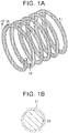
FIG. 1A is a schematic view showing the structure of a micro coil with a coating layer according to one embodiment of the invention; -
FIG. 1B is a cross-sectional view of the micro coil ofFIG. 1A , which is cut in a plane taken alongline 1B-1B inFIG. 1A ; -
FIG. 2A is a schematic view showing the structure of a micro coil body of the micro coil shown inFIG. 1A ; -
FIG. 2B is a cross-sectional view of the micro coil body ofFIG. 2A , which is cut in a plane taken alongline 2B-2B inFIG. 2A ; and -
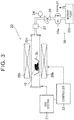
FIG. 3 is a schematic view of a CVD device used for producing micro coils with coating layers. - A micro coil with a coating layer according to one embodiment of the invention will be described referring to the drawings. The micro coil with the coating layer may be favorably used as a radio wave absorber included in a heating unit that heats an exhaust clean-up catalyst for cleaning up exhaust gas, in an emission control system of an internal combustion engine, for example. The heating unit generates heat when it is irradiated with microwaves.
- As shown in
FIG. 1A and FIG. 1B , the micro coil with the coating layer has amicro coil body 10, and acoating layer 11 formed on a surface of themicro coil body 10. - As shown in
FIG. 2A , themicro coil body 10 has a coil shape (helical shape). The coil diameter of themicro coil body 10 is within a range of submicron to several dozens of microns, and its length (axial length) is within a range of several dozens of microns to several hundreds of microns, for example. Themicro coil body 10 is a micro coil (which may be called "heat-resistant, insulating micro coil" when appropriate) having heat resistance and insulating capacity, and is composed of a coil-shaped material having heat resistance and insulating capacity. - The "heat resistance" refers to "heat resistance sufficient to keep the micro coil body from thermal decomposition and melting in a high-temperature environment (an environment of temperatures equal to or higher 500°C and equal to or lower than 1000°C, for example)". The "insulating capacity" refers to "insulating capacity equivalent to the volume resistivity equal to or lager than 106 Ωcm". The heat-resistant, insulating micro coil has the insulating capacity at ordinary temperatures.
- Examples of the heat-resistant, insulating material used for the
micro coil body 10 include one or more types of insulating inorganic materials (namely, inorganic materials of which the volume resistivity is 106 Ωcm or larger at ordinary temperatures) selected from metal oxides (e.g., titanium oxide (TiO2)) and semimetal nitrides (e.g., silicon nitride (Si3N4)). - More specifically, as the
micro coil body 10, a coil-shaped TiO2 micro coil composed of titanium oxide (TiO2), a coil-shaped Si3N4 micro coil composed of silicon nitride (Si3N4), or the like, may be used. These micro coils may be produced according to known methods (for example, see Japanese Patent Application Publication No.2011-148682 JP 2011-148682 A - The
coating layer 11 is formed on the entire area of the surface of themicro coil body 10, and forms a coil shape following the shape of themicro coil body 10. It is, however, to be noted that thecoating layer 11 is not necessarily formed on the entire area of the surface of themicro coil body 10, provided that at least a part of thecoating layer 11 has a coil shape following the coil shape of themicro coil body 10. Thus, thecoating layer 11 may be formed on a part of the surface of themicro coil body 10. In other words, thecoating layer 11 is only required to be shaped such that, when the micro coil with the coating layer is irradiated with radio waves, induced current is produced in thecoating layer 11 according to a magnetic-field component of the radio waves, and Joule heat is generated due to flow of the induced current in thecoating layer 11. - The thickness of the
coating layer 11 is, for example, equal to or larger than 0.1 µm and equal to or smaller than 10 µm, more preferably, equal to or larger than 0.2 µm and equal to or smaller than 2 µm. It is, however, to be noted that the thickness of thecoating layer 11 can be set as appropriate depending on its material. Thecoating layer 11 is not necessarily required to cover the entire area of the surface of themicro coil body 10, provided that themicro coil body 10 is surrounded with thecoating layer 11 so that induced current can be generated. - The
coating layer 11 is composed of one type or a mixture of two or more types of materials having heat resistance, and having electrical conductivity even under a high-temperature environment (e.g., an environment of temperatures equal to or higher than 500°C and equal to or lower than 1000°C), and an oxidizing atmosphere. - Examples of the material of the
coating layer 11 include one or more types of conductive metals selected from conductive noble metals (such as silver (Ag), platinum (Pt), and gold (Au)), and metals (such as zinc (Zn)) of which the oxides have conductivity. The conductive metal may be an alloy including the above-indicated metals, provided that the alloy has heat resistance, and has electrical conductivity even under the high-temperature environment and the oxidizing atmosphere. Examples of the material of thecoating layer 11 also include conductive metal oxides (for example, one or more types of oxides selected from silver oxide (Ag2O), zinc oxide (ZnO), etc.). Examples of the material of thecoating layer 11 further include conductive metal composite oxides (such as perovskite-type oxides). Examples of the perovskite-type oxides include perovskite-type oxides (such as La0.8Sr0.2CoO3, and La0.4Sr0.6Mn0.8Ni0.3) having NOx removing capability. It is known in the art that these perovskite-type oxides have NOx removing capability (for example, see "Reaction mechanism of direct decomposition of nitric oxide over Co- and Mn-based perovskite-type oxides", J Chem. Soc., Faraday Trans., 1998, Vol. 94 1887-1891, "Recent progress in catalytic NO decomposition", Comptes Rendus Chimie, 19 (2016), 1254-1265, etc.). - In the micro coil with the coating layer, the
coating layer 11 has electrical conductivity, and has a coil shape following the coil shape of themicro coil body 10. Therefore, when the micro coil with the coating layer is irradiated with microwaves (radio waves, electromagnetic waves), induced current is produced in the coil-shapedcoating layer 11 according to a magnetic-field component of the microwaves, and the induced current thus produced flows in the coil-shapedcoating layer 11, to generate Joule heat. Accordingly, even if themicro coil body 10 does not have electrical conductivity (namely, even if it has insulating capacity), the micro coil with the coating layer can function as a radio wave absorber that converts radio wave energy into thermal energy and generates heat. - In the micro coil with the coating layer, the
micro coil body 10 has heat resistance, and thecoating layer 11 "has heat resistance, and has electrical conductivity even under a high-temperature environment and an oxidizing atmosphere". Therefore, even when the micro coil with the coating layer is placed under a high-temperature environment and an oxidizing atmosphere, thecoating layer 11 can keep the coil shape and conductivity. Accordingly, the micro coil with the coating layer can function as a radio wave absorber, even under the high-temperature environment and oxidizing atmosphere. Accordingly, the micro coil with the coating layer may be placed in "an exhaust clean-up catalyst unit of an internal combustion engine" under a high-temperature environment and an oxidizing atmosphere. Further, in this case, the exhaust clean-up catalyst unit is provided with a device for transmitting microwaves (electromagnetic waves) to the micro coil with the coating layer placed inside the unit. - To produce the micro coil with the coating layer, the
micro coil body 10 is typically produced according to the known method as described above, using the material of themicro coil body 10 as described above. Then, a material of which thecoating layer 11 is composed is formed, in the form of a thin film, on the surface of themicro coil body 10, according to a known thin-film forming method as described below. - For example, the thin film (coating layer 11) may be formed by a gas phase method selected from CVD (Chemical Vapor Deposition) methods, PVD (Physical Vapor Deposition) methods, and so forth. Further, the thin film (coating layer 11) may also be formed according to a liquid phase method selected from a sol-gel method, a coprecipitation method, and so forth.
- According to the CVD method, energy, such as heat, light, and plasma, is applied to the thin-film forming material that is supplied as gas, for decomposition and reaction of the material gas molecules, so that an intermediate product is formed, and a thin film is deposited on a surface of an object on which the thin film (coating layer 11) is to be formed, through adsorption, reaction, and separation.
- Examples of the CVD method include a thermal CVD method, MOCVD (Metal Organic Chemical Vapor Deposition) method, RF plasma CVD method, light CVD method, laser CVD method, LPE (Liquid Phase Epitaxy) method, and other methods.
- According to the PVD method, a thin-film material that provides a thin film is once evaporated or gasified, with energy, such as heat or plasma, so as to form a thin film on a substrate. Examples of the PVD method include vacuum vapor deposition methods (e.g., resistance heating method, high-frequency induction heating deposition method, electronic beam deposition method, etc.), sputtering, ion plating, MBE (molecular beam epitaxy), laser ablation method, and other methods.
- By suitably selecting one of the above-indicated thin-film forming methods, a thin film of the material of the
coating layer 11 as described above is formed on the surface of themicro coil body 10, to form thecoating layer 11. In the following, the method for producing thecoating layer 11 will be more specifically described. - The micro coil with the coating layer may be produced, using a thermal CVD device. As shown in
FIG. 3 , the thermal CVD device includes aresistance heating furnace 20,gas system 21,controller 22, coolingtrap 23,pressure gauge 24,air valve 25, and apump unit 26. - The
resistance heating furnace 20 includes aquartz reaction tube 20a having interior space (chamber) isolated from the outside air, and aheater 20b for heating the interior space of thequartz reaction tube 20a. Thecontroller 22 is an electronic control unit that controls thegas system 21 and theresistance heating furnace 20. Thepump unit 26 includes amechanical booster pump 26a and arotary pump 26b. - The pressure in the interior space (chamber) can be reduced by operating the
pump unit 26 so as to suck and discharge gas in theresistance heating furnace 20, via thecooling trap 23. Further, theair valve 25 operates to control the flow rate of the gas passing therethough, so that the pressure in the interior space (chamber) can be controlled to a desired pressure. - The
micro coil body 10 as shown inFIG. 2A and FIG. 2B is placed in a heat-proof dish 30 set at a predetermined position in the interior space of theresistance heating furnace 20. Then, atmosphere gas within the internal space (chamber) is replaced with atmosphere gas (such as an oxygen atmosphere or an inert atmosphere) suitable for formation of thecoating layer 11, by use of thegas system 21. - Then, the interior space is heated to a temperature equal to or higher than a decomposition temperature of material gas (which will be described later) for forming the
coating layer 11. After completion of heating, gas including at least the material gas is supplied from thegas system 21 to the interior space. As a result, the material gas decomposes in the interior space and on the surface of themicro coil body 10, so that a decomposed component of the material gas is deposited on themicro coil body 10, so as to form a coating film that provides thecoating layer 11. - As the material gas, at least one of inorganic metal compounds and organic metal compounds including a component (metallic species) that constitutes the
coating layer 11 is suitably selected and used. When thecoating layer 11 is composed of a conductive metal composite oxide, two or more species of materials (for example, two or more species of organic metal compounds) are mixed together, according to two or more metallic species of the conductive metal composite compound, and the materials thus mixed are gasified, to prepare material gas. - As the material gas, gas obtained by gasifying one or more species selected from metallic acetates, such as silver acetate (CH3COOAg), zinc acetate ((CH3COO)2Zn), lanthanum acetate ((CH3COO)3La), strontium nitrate (Sr(NO3)2), barium acetate ((CH3COO2)Ba), and iron acetate ((CH3COO)2Fe), for example, may be used.
- As another example of a method for producing the micro coil with the coating layer, a production method using the coprecipitation method will be described. This production method is favorably used when the
coating layer 11 is composed of a conductive metal composite oxide. Initially, themicro coil body 10 is mixed with two or more species of metallic acetates, or the like, as materials of the conductive metal composite oxide, and a solution is prepared by dissolving the mixture in water. Then, ammonia water (NH3 water), or the like, is added to the solution, so that the pH of the solution is controlled to be equal to or larger than pH 12, and equal to or smaller than pH 14. As a result, respective types of metallic ions in the solution produced by dissolving the two or more species of metallic acetates in water form metallic hydroxides, which are co-precipitated with themicro coil body 10. The metallic hydroxides are adsorbed on the surface of themicro coil body 10. Then, themicro coil body 10 on which the metallic hydroxides are adsorbed is collected from the mixed solution of which the pH has been controlled, through filtering or centrifugal separation. Then, the collectedmicro coil body 10 is fired at a given temperature (e.g., a temperature equal to or higher than 500°C and equal to or lower than 1200°C). In this manner, thecoating layer 11 composed of the conductive metal composite oxide is formed on the surface of themicro coil body 10. - In the micro coil with the coating layer according to the above embodiment of the invention, the
micro coil body 10 has heat resistance, and thecoating layer 11 has electrical conductivity even under a high-temperature environment and an oxidizing atmosphere; therefore, the coil-shapedcoating layer 11 can keep conductivity even under the high-temperature environment and oxidizing atmosphere. Accordingly, the micro coil with the coating layer can function as a radio wave absorber, even under the high-temperature environment and oxidizing atmosphere (for example, in an exhaust clean-up catalyst device of an internal combustion engine). - While one embodiment of the invention has been specifically described above, the invention is not limited to the above embodiment, but the embodiment may be subjected to various modifications based on the technical concept of the invention.
- For example, as the
micro coil body 10, a micro coil made of a material having electrical conductivity may be employed. For example, a carbon micro coil (micro coil made of carbon) has conductivity, but is oxidized and gasified under a high-temperature environment and an oxidizing atmosphere. However, if the whole (the entire area of the surface) of the carbon micro coil is coated with thecoating layer 11, the gasification does not take place, and the carbon micro coil can be used as themicro coil body 10. Further, a TiC micro coil (micro coil made of titanium carbide (TiC)) has electrical conductivity, but it loses conductivity when oxidized under a high-temperature environment and an oxidizing atmosphere. However, if the whole of the TiC micro coil is coated with thecoating layer 11, the oxidization does not take place, and the TiC micro coil can be used as themicro coil body 10 that keeps conductivity. - When the micro coil with the coating layer using a micro coil having conductivity, such as the "carbon micro coil and TiC micro coil", as the
micro coil body 10 is irradiated with radio waves, such as microwaves, induced current is produced in themicro coil body 10 as well as thecoating layer 11, due to a magnetic-field component of the radio waves. Then, the induced current thus produced flows in themicro coil body 10 and thecoating layer 11, so that Joule heat is generated. Accordingly, the micro coil with the coating layer can "convert radio wave energy into thermal energy" with higher efficiency. Thus, the micro coil with the coating layer, which has excellent energy efficiency, is provided. - When the TiC micro coil is used as the
micro coil body 10, and the TiC micro coil, except for a part of the surface thereof, is coated with thecoating layer 11, the part of the surface which is not coated with thecoating layer 11 is oxidized and loses conductivity. However, even in this case, thecoating layer 11 keeps conductivity; therefore, the resulting product can be used as a micro coil (radio wave absorber) that can "convert radio wave energy into thermal energy" under a high-temperature environment and an oxidizing atmosphere. - As another modified example, in the micro coil with the coating layer, the
coating layer 11 may consist of two or more layers. In this case, the above-indicated material that forms thecoating layer 11 may form each layer of the two or more layers. - Further, in this case, the first layer formed on the surface of the
micro coil body 10 may be provided by a layer having electrical conductivity, and one or more layers laminated on the first layer may be provided by a protective layer or layers having heat resistance and serving to protect the first layer. In this case, the first layer is covered with the protective layer(s), and is thus prevented from being directly exposed to an oxidizing atmosphere. Accordingly, the first layer is less likely or unlikely to be altered and have reduced conductivity, under a high-temperature environment and an oxidizing atmosphere. As a result, the micro coil with the coating layer having the protective layer(s) as described above can function as a radio wave absorber, even under a high-temperature environment and an oxidizing atmosphere. - Examples of the material that forms the first layer include one or more types of conductive metals selected from iron (Fe), copper (Cu), and so forth. Examples of the material that forms the protective layer include the above-described material that forms the
coating layer 11, passive state (metal having a surface on which an oxide coating is formed) of one or more types of metals selected from aluminum (Al), chromium (Cr), titanium (Ti), etc., metal having a surface on which an oxide coating can be formed, and a material, such as a metallic oxide, which exhibits stability against a high-temperature, oxidizing atmosphere. - When the micro coil with the coating layer is produced, the
coating layer 11 that is shaped such that induced current is produced when it is irradiated with radio waves may be intentionally formed on only a part of the surface of themicro coil body 10, in the following manner. For example, a mask material is formed on a portion of themicro coil body 10 other than a portion on which thecoating layer 11 is to be formed, and thecoating layer 11 is formed on the surface of themicro coil body 10 in this condition, by the method as described above. Then, the mask material is removed.
Claims (8)
- A micro coil comprising:a micro coil body (10) having heat resistance sufficient to keep the micro coil body (10) from thermal decomposition and melting in a high-temperature environment; anda coating layer (11) provided on a surface of the micro coil body (10), the coating layer (11) having the heat resistance, and having electrical conductivity under the high-temperature environment and an oxidizing atmosphere, whereinthe coating layer (11) has a shape that causes induced current to be produced according to a magnetic-field component of radio waves, when the micro coil receives the radio waves.
- The micro coil according to claim 1, wherein:the micro coil body (10) comprises one of a silicon nitride micro coil composed of silicon nitride, a titanium oxide micro coil composed of titanium oxide, and a titanium carbide micro coil composed of titanium carbide; andthe coating layer (11) is configured to cover a part or an entire area of the surface of the micro coil body (10).
- The micro coil according to claim 1, wherein:the micro coil body (10) comprises a carbon micro coil composed of carbon, or a titanium carbide micro coil composed of titanium carbide; andthe coating layer (11) is configured to cover an entire area of the surface of the micro coil body (10).
- The micro coil according to any one of claims 1 to 3, wherein the coating layer (11) comprises at least one of conductive metals, conductive metal oxides, and conductive metal composite oxides.
- The micro coil according to claim 4, wherein the conductive metals include one or more types of metal selected from platinum, gold, zinc, and silver, and the conductive metal oxides include one or more types of metal oxide selected from silver oxide and zinc oxide, while the conductive metal composite oxides include perovskite oxide.
- The micro coil according to claim 5, wherein the perovskite oxide is selected from perovskite oxides having NOx removing capability.
- The micro coil according to any one of claims 1 to 6, wherein the coating layer (11) has a coil shape following a coil shape of the micro coil body (10).
- The micro coil according to any one of claims 1 to 7, wherein the high-temperature environment is an environment of temperatures equal to or higher 500°C and equal to or lower than 1000°C.
Applications Claiming Priority (1)
| Application Number | Priority Date | Filing Date | Title |
|---|---|---|---|
| JP2017096938A JP6724859B2 (en) | 2017-05-16 | 2017-05-16 | Micro coil with coating layer |
Publications (2)
| Publication Number | Publication Date |
|---|---|
| EP3406872A1 true EP3406872A1 (en) | 2018-11-28 |
| EP3406872B1 EP3406872B1 (en) | 2020-02-19 |
Family
ID=62196375
Family Applications (1)
| Application Number | Title | Priority Date | Filing Date |
|---|---|---|---|
| EP18172704.1A Active EP3406872B1 (en) | 2017-05-16 | 2018-05-16 | Micro coil |
Country Status (12)
| Country | Link |
|---|---|
| US (1) | US10493435B2 (en) |
| EP (1) | EP3406872B1 (en) |
| JP (1) | JP6724859B2 (en) |
| KR (1) | KR20180125892A (en) |
| CN (1) | CN108882423B (en) |
| AU (1) | AU2018203407A1 (en) |
| BR (1) | BR102018009923A2 (en) |
| CA (1) | CA3004981A1 (en) |
| ES (1) | ES2779041T3 (en) |
| MX (1) | MX2018006078A (en) |
| PH (1) | PH12018050196A1 (en) |
| TW (1) | TW201900954A (en) |
Citations (4)
| Publication number | Priority date | Publication date | Assignee | Title |
|---|---|---|---|---|
| DE102008047132A1 (en) * | 2007-09-18 | 2009-04-16 | GM Global Technology Operations, Inc., Detroit | Electrically heated particle material filter arrangement for use in diesel internal combustion engine of motor vehicle, has frequency-selective segment passing through microwave energy in one frequency range and does not in another range |
| JP2011148682A (en) | 2009-12-25 | 2011-08-04 | Tokyo Univ Of Science | Ceramic spring and method for manufacturing the same |
| JP2012012736A (en) | 2010-07-02 | 2012-01-19 | Japan Fine Ceramics Center | Method of manufacturing coil-shaped carbon fiber with supported magnetic material as ultra wide band electromagnetic wave absorber |
| EP2767691A1 (en) * | 2011-09-15 | 2014-08-20 | Imagineering, Inc. | Heating device |
Family Cites Families (13)
| Publication number | Priority date | Publication date | Assignee | Title |
|---|---|---|---|---|
| JP2001146644A (en) | 1999-11-19 | 2001-05-29 | Seiji Motojima | Coiled carbon fiber having ferromagnetism, method for producing the same, coiled carbon fiber composite having ferromagnetism and electric wave absorber |
| JP2003003336A (en) * | 2001-06-18 | 2003-01-08 | Seiji Motojima | Coil-shaped carbon fiber and use of the same |
| JP2003164765A (en) * | 2001-11-30 | 2003-06-10 | Toyota Motor Corp | Ferromagnetic catalyst for exhaust gas purification and exhaust gas purification device |
| JP2009147133A (en) * | 2007-12-14 | 2009-07-02 | Idemitsu Kosan Co Ltd | Micro ceramic coil and manufacturing method thereof |
| US9860968B2 (en) | 2011-09-22 | 2018-01-02 | Imagineering, Inc. | Plasma generating device, and internal combustion engine |
| CN103366916A (en) * | 2012-03-31 | 2013-10-23 | 深圳光启创新技术有限公司 | Wireless energy receiving coil and wireless energy transmission system |
| CN103573247B (en) * | 2012-07-20 | 2019-05-17 | 中国石油集团长城钻探工程有限公司 | Induction logging parallel plane coil and induction logging equipment |
| CN202832477U (en) * | 2012-07-20 | 2013-03-27 | 中国石油集团长城钻探工程有限公司 | Parallel plane coils used for induction logging and induction logging equipment |
| US9685269B2 (en) * | 2012-10-18 | 2017-06-20 | Ford Global Technologies, Llc | Method of forming an insulated electric conductor |
| JP6328450B2 (en) | 2014-03-12 | 2018-05-23 | 株式会社西澤 | Electromagnetic wave absorbing coating agent, sheet coated with coating agent, and method for producing coating agent |
| CN204906753U (en) * | 2015-06-30 | 2015-12-23 | 佛山市顺德区美的电热电器制造有限公司 | Coil panel and contain electromagnetic heating equipment of this coil panel |
| CN106344396A (en) * | 2015-12-03 | 2017-01-25 | 福建星宏新材料科技有限公司 | Micro-carbon spring compound ceramic ball |
| CN106345060A (en) * | 2016-10-25 | 2017-01-25 | 福建星宏新材料科技有限公司 | Physical therapy combination body capable of adjusting biological electromagnetic field of human body and application product of physical therapy combination body |
-
2017
- 2017-05-16 JP JP2017096938A patent/JP6724859B2/en not_active Expired - Fee Related
-
2018
- 2018-05-09 CN CN201810437360.6A patent/CN108882423B/en not_active Expired - Fee Related
- 2018-05-11 KR KR1020180054127A patent/KR20180125892A/en not_active Ceased
- 2018-05-14 US US15/978,469 patent/US10493435B2/en not_active Expired - Fee Related
- 2018-05-15 TW TW107116372A patent/TW201900954A/en unknown
- 2018-05-15 CA CA3004981A patent/CA3004981A1/en not_active Abandoned
- 2018-05-15 AU AU2018203407A patent/AU2018203407A1/en not_active Abandoned
- 2018-05-16 PH PH12018050196A patent/PH12018050196A1/en unknown
- 2018-05-16 MX MX2018006078A patent/MX2018006078A/en unknown
- 2018-05-16 EP EP18172704.1A patent/EP3406872B1/en active Active
- 2018-05-16 ES ES18172704T patent/ES2779041T3/en active Active
- 2018-05-16 BR BR102018009923-0A patent/BR102018009923A2/en not_active IP Right Cessation
Patent Citations (4)
| Publication number | Priority date | Publication date | Assignee | Title |
|---|---|---|---|---|
| DE102008047132A1 (en) * | 2007-09-18 | 2009-04-16 | GM Global Technology Operations, Inc., Detroit | Electrically heated particle material filter arrangement for use in diesel internal combustion engine of motor vehicle, has frequency-selective segment passing through microwave energy in one frequency range and does not in another range |
| JP2011148682A (en) | 2009-12-25 | 2011-08-04 | Tokyo Univ Of Science | Ceramic spring and method for manufacturing the same |
| JP2012012736A (en) | 2010-07-02 | 2012-01-19 | Japan Fine Ceramics Center | Method of manufacturing coil-shaped carbon fiber with supported magnetic material as ultra wide band electromagnetic wave absorber |
| EP2767691A1 (en) * | 2011-09-15 | 2014-08-20 | Imagineering, Inc. | Heating device |
Non-Patent Citations (4)
| Title |
|---|
| "Reaction mechanism of direct decomposition of nitric oxide over Co- and Mn-based perovskite-type oxides", J CHEM. SOC., FARADAY TRANS., vol. 94, 1998, pages 1887 - 1891 |
| "Recent progress in catalytic NO decomposition", COMPTES RENDUS CHIMIE, vol. 19, 2016, pages 1254 - 1265 |
| CHEMICAL PHYSICS LETTERS, vol. 378, 2003, pages 111 - 116 |
| JOURNAL OF THE CERAMIC SOCIETY OF JAPAN, vol. 116, no. 9, 2008, pages 921 - 927 |
Also Published As
| Publication number | Publication date |
|---|---|
| KR20180125892A (en) | 2018-11-26 |
| AU2018203407A1 (en) | 2018-12-06 |
| CN108882423B (en) | 2021-04-23 |
| US20180333700A1 (en) | 2018-11-22 |
| MX2018006078A (en) | 2019-02-08 |
| CA3004981A1 (en) | 2018-11-16 |
| PH12018050196A1 (en) | 2019-01-28 |
| EP3406872B1 (en) | 2020-02-19 |
| CN108882423A (en) | 2018-11-23 |
| US10493435B2 (en) | 2019-12-03 |
| JP2018193630A (en) | 2018-12-06 |
| BR102018009923A2 (en) | 2018-12-04 |
| ES2779041T3 (en) | 2020-08-13 |
| JP6724859B2 (en) | 2020-07-15 |
| TW201900954A (en) | 2019-01-01 |
Similar Documents
| Publication | Publication Date | Title |
|---|---|---|
| US6014073A (en) | Temperature sensor element, temperature sensor having the same and method for producing the same temperature sensor element | |
| EP0964433B1 (en) | Multiple-layered ceramic heater | |
| EP0574012B1 (en) | Exhaust gas catalytic purifier construction | |
| US20150027543A1 (en) | Oxide Compounds as a Coating Composition | |
| US8815167B2 (en) | Electrode, electrically heating type catalyst device using same, and manufacturing method of electrically heating type catalyst device | |
| CN104871305B (en) | Thermal Radiation Barriers for Substrate Processing Chamber Components | |
| WO2004068541A2 (en) | Wafer handling apparatus | |
| WO2004038768A1 (en) | Encapsulated graphite heater and process | |
| JP2021526032A (en) | Aerosol generator with heat coating | |
| EP3406872B1 (en) | Micro coil | |
| EP3435744B1 (en) | Method and device for additively manufacturing components | |
| EP3031957A1 (en) | Methods of forming an article using electrophoretic deposition, and related articles | |
| CA2137603C (en) | A boron-doped diamond resistance heater | |
| JP2013093302A (en) | Heater | |
| US7601324B1 (en) | Method for synthesizing metal oxide | |
| JP5118057B2 (en) | Metal tube | |
| JP6115823B2 (en) | Metal nitride material for thermistor, manufacturing method thereof, and film type thermistor sensor | |
| EP3607109A1 (en) | Method of producing a ntcr sensor | |
| JP2006143491A (en) | Carbon nanotube production method and apparatus | |
| JPH0978237A (en) | Production of thin film and device therefor | |
| JP3769065B2 (en) | Zirconia-coated member, manufacturing method thereof, manufacturing apparatus thereof, and turbine member | |
| JPH0363538A (en) | Pressure sensor | |
| JP4789055B2 (en) | Method for producing functional filamentous material | |
| JP4903473B2 (en) | Heating element CVD equipment | |
| JP2951727B2 (en) | Temperature sensor element, temperature sensor having the same, and method of manufacturing temperature sensor element |
Legal Events
| Date | Code | Title | Description |
|---|---|---|---|
| PUAI | Public reference made under article 153(3) epc to a published international application that has entered the european phase |
Free format text: ORIGINAL CODE: 0009012 |
|
| STAA | Information on the status of an ep patent application or granted ep patent |
Free format text: STATUS: REQUEST FOR EXAMINATION WAS MADE |
|
| 17P | Request for examination filed |
Effective date: 20180615 |
|
| AK | Designated contracting states |
Kind code of ref document: A1 Designated state(s): AL AT BE BG CH CY CZ DE DK EE ES FI FR GB GR HR HU IE IS IT LI LT LU LV MC MK MT NL NO PL PT RO RS SE SI SK SM TR |
|
| AX | Request for extension of the european patent |
Extension state: BA ME |
|
| RIC1 | Information provided on ipc code assigned before grant |
Ipc: F01N 3/20 20060101AFI20190730BHEP |
|
| GRAP | Despatch of communication of intention to grant a patent |
Free format text: ORIGINAL CODE: EPIDOSNIGR1 |
|
| STAA | Information on the status of an ep patent application or granted ep patent |
Free format text: STATUS: GRANT OF PATENT IS INTENDED |
|
| INTG | Intention to grant announced |
Effective date: 20190911 |
|
| GRAS | Grant fee paid |
Free format text: ORIGINAL CODE: EPIDOSNIGR3 |
|
| GRAA | (expected) grant |
Free format text: ORIGINAL CODE: 0009210 |
|
| STAA | Information on the status of an ep patent application or granted ep patent |
Free format text: STATUS: THE PATENT HAS BEEN GRANTED |
|
| AK | Designated contracting states |
Kind code of ref document: B1 Designated state(s): AL AT BE BG CH CY CZ DE DK EE ES FI FR GB GR HR HU IE IS IT LI LT LU LV MC MK MT NL NO PL PT RO RS SE SI SK SM TR |
|
| REG | Reference to a national code |
Ref country code: CH Ref legal event code: EP |
|
| REG | Reference to a national code |
Ref country code: DE Ref legal event code: R096 Ref document number: 602018002486 Country of ref document: DE |
|
| REG | Reference to a national code |
Ref country code: AT Ref legal event code: REF Ref document number: 1235212 Country of ref document: AT Kind code of ref document: T Effective date: 20200315 |
|
| REG | Reference to a national code |
Ref country code: IE Ref legal event code: FG4D |
|
| REG | Reference to a national code |
Ref country code: NL Ref legal event code: MP Effective date: 20200219 |
|
| PG25 | Lapsed in a contracting state [announced via postgrant information from national office to epo] |
Ref country code: NO Free format text: LAPSE BECAUSE OF FAILURE TO SUBMIT A TRANSLATION OF THE DESCRIPTION OR TO PAY THE FEE WITHIN THE PRESCRIBED TIME-LIMIT Effective date: 20200519 Ref country code: RS Free format text: LAPSE BECAUSE OF FAILURE TO SUBMIT A TRANSLATION OF THE DESCRIPTION OR TO PAY THE FEE WITHIN THE PRESCRIBED TIME-LIMIT Effective date: 20200219 Ref country code: FI Free format text: LAPSE BECAUSE OF FAILURE TO SUBMIT A TRANSLATION OF THE DESCRIPTION OR TO PAY THE FEE WITHIN THE PRESCRIBED TIME-LIMIT Effective date: 20200219 |
|
| REG | Reference to a national code |
Ref country code: ES Ref legal event code: FG2A Ref document number: 2779041 Country of ref document: ES Kind code of ref document: T3 Effective date: 20200813 |
|
| REG | Reference to a national code |
Ref country code: LT Ref legal event code: MG4D |
|
| PG25 | Lapsed in a contracting state [announced via postgrant information from national office to epo] |
Ref country code: BG Free format text: LAPSE BECAUSE OF FAILURE TO SUBMIT A TRANSLATION OF THE DESCRIPTION OR TO PAY THE FEE WITHIN THE PRESCRIBED TIME-LIMIT Effective date: 20200519 Ref country code: IS Free format text: LAPSE BECAUSE OF FAILURE TO SUBMIT A TRANSLATION OF THE DESCRIPTION OR TO PAY THE FEE WITHIN THE PRESCRIBED TIME-LIMIT Effective date: 20200619 Ref country code: GR Free format text: LAPSE BECAUSE OF FAILURE TO SUBMIT A TRANSLATION OF THE DESCRIPTION OR TO PAY THE FEE WITHIN THE PRESCRIBED TIME-LIMIT Effective date: 20200520 Ref country code: LV Free format text: LAPSE BECAUSE OF FAILURE TO SUBMIT A TRANSLATION OF THE DESCRIPTION OR TO PAY THE FEE WITHIN THE PRESCRIBED TIME-LIMIT Effective date: 20200219 Ref country code: SE Free format text: LAPSE BECAUSE OF FAILURE TO SUBMIT A TRANSLATION OF THE DESCRIPTION OR TO PAY THE FEE WITHIN THE PRESCRIBED TIME-LIMIT Effective date: 20200219 Ref country code: HR Free format text: LAPSE BECAUSE OF FAILURE TO SUBMIT A TRANSLATION OF THE DESCRIPTION OR TO PAY THE FEE WITHIN THE PRESCRIBED TIME-LIMIT Effective date: 20200219 |
|
| PG25 | Lapsed in a contracting state [announced via postgrant information from national office to epo] |
Ref country code: NL Free format text: LAPSE BECAUSE OF FAILURE TO SUBMIT A TRANSLATION OF THE DESCRIPTION OR TO PAY THE FEE WITHIN THE PRESCRIBED TIME-LIMIT Effective date: 20200219 |
|
| PG25 | Lapsed in a contracting state [announced via postgrant information from national office to epo] |
Ref country code: DK Free format text: LAPSE BECAUSE OF FAILURE TO SUBMIT A TRANSLATION OF THE DESCRIPTION OR TO PAY THE FEE WITHIN THE PRESCRIBED TIME-LIMIT Effective date: 20200219 Ref country code: SK Free format text: LAPSE BECAUSE OF FAILURE TO SUBMIT A TRANSLATION OF THE DESCRIPTION OR TO PAY THE FEE WITHIN THE PRESCRIBED TIME-LIMIT Effective date: 20200219 Ref country code: PT Free format text: LAPSE BECAUSE OF FAILURE TO SUBMIT A TRANSLATION OF THE DESCRIPTION OR TO PAY THE FEE WITHIN THE PRESCRIBED TIME-LIMIT Effective date: 20200712 Ref country code: SM Free format text: LAPSE BECAUSE OF FAILURE TO SUBMIT A TRANSLATION OF THE DESCRIPTION OR TO PAY THE FEE WITHIN THE PRESCRIBED TIME-LIMIT Effective date: 20200219 Ref country code: LT Free format text: LAPSE BECAUSE OF FAILURE TO SUBMIT A TRANSLATION OF THE DESCRIPTION OR TO PAY THE FEE WITHIN THE PRESCRIBED TIME-LIMIT Effective date: 20200219 Ref country code: EE Free format text: LAPSE BECAUSE OF FAILURE TO SUBMIT A TRANSLATION OF THE DESCRIPTION OR TO PAY THE FEE WITHIN THE PRESCRIBED TIME-LIMIT Effective date: 20200219 Ref country code: CZ Free format text: LAPSE BECAUSE OF FAILURE TO SUBMIT A TRANSLATION OF THE DESCRIPTION OR TO PAY THE FEE WITHIN THE PRESCRIBED TIME-LIMIT Effective date: 20200219 Ref country code: RO Free format text: LAPSE BECAUSE OF FAILURE TO SUBMIT A TRANSLATION OF THE DESCRIPTION OR TO PAY THE FEE WITHIN THE PRESCRIBED TIME-LIMIT Effective date: 20200219 |
|
| REG | Reference to a national code |
Ref country code: AT Ref legal event code: MK05 Ref document number: 1235212 Country of ref document: AT Kind code of ref document: T Effective date: 20200219 |
|
| REG | Reference to a national code |
Ref country code: DE Ref legal event code: R097 Ref document number: 602018002486 Country of ref document: DE |
|
| PLBE | No opposition filed within time limit |
Free format text: ORIGINAL CODE: 0009261 |
|
| STAA | Information on the status of an ep patent application or granted ep patent |
Free format text: STATUS: NO OPPOSITION FILED WITHIN TIME LIMIT |
|
| 26N | No opposition filed |
Effective date: 20201120 |
|
| PG25 | Lapsed in a contracting state [announced via postgrant information from national office to epo] |
Ref country code: MC Free format text: LAPSE BECAUSE OF FAILURE TO SUBMIT A TRANSLATION OF THE DESCRIPTION OR TO PAY THE FEE WITHIN THE PRESCRIBED TIME-LIMIT Effective date: 20200219 Ref country code: AT Free format text: LAPSE BECAUSE OF FAILURE TO SUBMIT A TRANSLATION OF THE DESCRIPTION OR TO PAY THE FEE WITHIN THE PRESCRIBED TIME-LIMIT Effective date: 20200219 |
|
| PG25 | Lapsed in a contracting state [announced via postgrant information from national office to epo] |
Ref country code: PL Free format text: LAPSE BECAUSE OF FAILURE TO SUBMIT A TRANSLATION OF THE DESCRIPTION OR TO PAY THE FEE WITHIN THE PRESCRIBED TIME-LIMIT Effective date: 20200219 Ref country code: SI Free format text: LAPSE BECAUSE OF FAILURE TO SUBMIT A TRANSLATION OF THE DESCRIPTION OR TO PAY THE FEE WITHIN THE PRESCRIBED TIME-LIMIT Effective date: 20200219 |
|
| REG | Reference to a national code |
Ref country code: BE Ref legal event code: MM Effective date: 20200531 |
|
| PG25 | Lapsed in a contracting state [announced via postgrant information from national office to epo] |
Ref country code: LU Free format text: LAPSE BECAUSE OF NON-PAYMENT OF DUE FEES Effective date: 20200516 |
|
| PG25 | Lapsed in a contracting state [announced via postgrant information from national office to epo] |
Ref country code: IE Free format text: LAPSE BECAUSE OF NON-PAYMENT OF DUE FEES Effective date: 20200516 |
|
| PG25 | Lapsed in a contracting state [announced via postgrant information from national office to epo] |
Ref country code: BE Free format text: LAPSE BECAUSE OF NON-PAYMENT OF DUE FEES Effective date: 20200531 |
|
| REG | Reference to a national code |
Ref country code: CH Ref legal event code: PL |
|
| PG25 | Lapsed in a contracting state [announced via postgrant information from national office to epo] |
Ref country code: LI Free format text: LAPSE BECAUSE OF NON-PAYMENT OF DUE FEES Effective date: 20210531 Ref country code: CH Free format text: LAPSE BECAUSE OF NON-PAYMENT OF DUE FEES Effective date: 20210531 |
|
| PGFP | Annual fee paid to national office [announced via postgrant information from national office to epo] |
Ref country code: GB Payment date: 20220324 Year of fee payment: 5 |
|
| PG25 | Lapsed in a contracting state [announced via postgrant information from national office to epo] |
Ref country code: TR Free format text: LAPSE BECAUSE OF FAILURE TO SUBMIT A TRANSLATION OF THE DESCRIPTION OR TO PAY THE FEE WITHIN THE PRESCRIBED TIME-LIMIT Effective date: 20200219 Ref country code: MT Free format text: LAPSE BECAUSE OF FAILURE TO SUBMIT A TRANSLATION OF THE DESCRIPTION OR TO PAY THE FEE WITHIN THE PRESCRIBED TIME-LIMIT Effective date: 20200219 Ref country code: CY Free format text: LAPSE BECAUSE OF FAILURE TO SUBMIT A TRANSLATION OF THE DESCRIPTION OR TO PAY THE FEE WITHIN THE PRESCRIBED TIME-LIMIT Effective date: 20200219 |
|
| PGFP | Annual fee paid to national office [announced via postgrant information from national office to epo] |
Ref country code: FR Payment date: 20220321 Year of fee payment: 5 |
|
| PG25 | Lapsed in a contracting state [announced via postgrant information from national office to epo] |
Ref country code: MK Free format text: LAPSE BECAUSE OF FAILURE TO SUBMIT A TRANSLATION OF THE DESCRIPTION OR TO PAY THE FEE WITHIN THE PRESCRIBED TIME-LIMIT Effective date: 20200219 Ref country code: AL Free format text: LAPSE BECAUSE OF FAILURE TO SUBMIT A TRANSLATION OF THE DESCRIPTION OR TO PAY THE FEE WITHIN THE PRESCRIBED TIME-LIMIT Effective date: 20200219 |
|
| PGFP | Annual fee paid to national office [announced via postgrant information from national office to epo] |
Ref country code: IT Payment date: 20220412 Year of fee payment: 5 Ref country code: ES Payment date: 20220602 Year of fee payment: 5 Ref country code: DE Payment date: 20220322 Year of fee payment: 5 |
|
| REG | Reference to a national code |
Ref country code: DE Ref legal event code: R084 Ref document number: 602018002486 Country of ref document: DE |
|
| REG | Reference to a national code |
Ref country code: GB Ref legal event code: 746 Effective date: 20230103 |
|
| P01 | Opt-out of the competence of the unified patent court (upc) registered |
Effective date: 20230427 |
|
| REG | Reference to a national code |
Ref country code: DE Ref legal event code: R119 Ref document number: 602018002486 Country of ref document: DE |
|
| GBPC | Gb: european patent ceased through non-payment of renewal fee |
Effective date: 20230516 |
|
| PG25 | Lapsed in a contracting state [announced via postgrant information from national office to epo] |
Ref country code: IT Free format text: LAPSE BECAUSE OF NON-PAYMENT OF DUE FEES Effective date: 20230516 Ref country code: DE Free format text: LAPSE BECAUSE OF NON-PAYMENT OF DUE FEES Effective date: 20231201 Ref country code: GB Free format text: LAPSE BECAUSE OF NON-PAYMENT OF DUE FEES Effective date: 20230516 |
|
| PG25 | Lapsed in a contracting state [announced via postgrant information from national office to epo] |
Ref country code: FR Free format text: LAPSE BECAUSE OF NON-PAYMENT OF DUE FEES Effective date: 20230531 |
|
| REG | Reference to a national code |
Ref country code: ES Ref legal event code: FD2A Effective date: 20240627 |
|
| PG25 | Lapsed in a contracting state [announced via postgrant information from national office to epo] |
Ref country code: ES Free format text: LAPSE BECAUSE OF NON-PAYMENT OF DUE FEES Effective date: 20230517 |
|
| PG25 | Lapsed in a contracting state [announced via postgrant information from national office to epo] |
Ref country code: ES Free format text: LAPSE BECAUSE OF NON-PAYMENT OF DUE FEES Effective date: 20230517 |