EP3406504A1 - Warning system for a track worksite and method for operating a track worksite - Google Patents
Warning system for a track worksite and method for operating a track worksite Download PDFInfo
- Publication number
- EP3406504A1 EP3406504A1 EP18171204.3A EP18171204A EP3406504A1 EP 3406504 A1 EP3406504 A1 EP 3406504A1 EP 18171204 A EP18171204 A EP 18171204A EP 3406504 A1 EP3406504 A1 EP 3406504A1
- Authority
- EP
- European Patent Office
- Prior art keywords
- warning
- track
- sensor
- area
- transmitter
- Prior art date
- Legal status (The legal status is an assumption and is not a legal conclusion. Google has not performed a legal analysis and makes no representation as to the accuracy of the status listed.)
- Granted
Links
Images
Classifications
-
- B—PERFORMING OPERATIONS; TRANSPORTING
- B61—RAILWAYS
- B61L—GUIDING RAILWAY TRAFFIC; ENSURING THE SAFETY OF RAILWAY TRAFFIC
- B61L23/00—Control, warning, or like safety means along the route or between vehicles or vehicle trains
- B61L23/06—Control, warning, or like safety means along the route or between vehicles or vehicle trains for warning men working on the route
Definitions
- the field-side warning of the track workers takes place in the entire area of the track construction site via warning devices set up in the warning areas - the field-side warning devices are thus independent of the position of the track construction machine. An alert is therefore always in the entire area of the track construction site instead.
Abstract
Warnsystem für eine Gleisbaustelle, mit einem in eine Mehrzahl von Warnbereichen (W1, W2, W3) unterteilten Gleisabschnitt (20), jeweils einer an der Grenze zwischen aneinandergrenzenden Warnbereichen (W1, W2, W3) angeordneten Grenzmarkierung (G1, G2, G3, G4, G5, G6), wenigstens einem in jedem Warnbereich (W1, W2, W3) angeordneten Warngeber (40), und einer auf dem Gleisabschnitt (20) fahrenden Gleisbaumaschine (10) mit einem beim Übertritt von einem Warnbereich (W1, W2, W3) in einen anderen Warnbereich (W1, W2, W3) die Grenzmarkierung (G1, G2, G3, G4, G5, G6) erfassenden Sensor (12, 14), wobei das Warnsystem anhand der zuletzt vom Sensor (12, 14) erfassten Grenzmarkierung (G1, G2, G3, G4, G5, G6) zum Bestimmen eines aktuellen Warnbereichs (W1, W2, W3), in dem sich die Gleisbaumaschine (10) befindet, und zum Ausgeben eines Warnsignals durch ausschließlich den wenigstens einen Warngeber (40) im aktuellen Warnbereich (W1, W2, W3) eingerichtet ist.A warning system for a track construction site, comprising a track section (20) subdivided into a plurality of warning areas (W1, W2, W3), each of a boundary marking (G1, G2, G3, G4) arranged at the border between adjoining warning areas (W1, W2, W3) , G5, G6), at least one warning transmitter (40) arranged in each warning area (W1, W2, W3), and a track-laying machine (10) traveling on the track section (20) with a warning zone (W1, W2, W3 ) in another warning area (W1, W2, W3) the boundary marking (G1, G2, G3, G4, G5, G6) detecting sensor (12, 14), wherein the warning system based on the last detected by the sensor (12, 14) boundary marker (G1, G2, G3, G4, G5, G6) for determining a current warning range (W1, W2, W3) in which the track-laying machine (10) is located and for outputting a warning signal by only the at least one warning transmitter (40) in the current warning area (W1, W2, W3).
Description
Die Erfindung betrifft ein Warnsystem für eine Gleisbaustelle und ein Verfahren zum Betreiben einer Gleisbaustelle mit einem von einer Gleisbaumaschine befahrenen, zu sichernden Gleisabschnitt und einem dem zu sichernden Gleisabschnitt benachbart angeordneten Nebengleis.The invention relates to a warning system for a track construction site and to a method for operating a track construction site with a track section to be secured, which is to be secured by a track-laying machine, and a siding arranged adjacent to the track section to be secured.
Bei Großgleisbaustellen, die Arbeiten mit Gleisbaumaschinen erfordern, wird in der Regel auch ein Einsatz von Seitenläufern neben den Gleisbaumaschinen sowie Arbeitsgruppen hinter und vor der Gleisbaumaschine benötigt. Durch Zugfahrten im befahrenen Nachbargleis und durch die Gleisbaumaschine können Seitenläufer und Arbeitsgruppen mit erhöhtem Risiko verletzt oder gar getötet werden.In large-scale construction sites, which require work with track-laying machines, it is generally also necessary to use side-runners in addition to the track-laying machines and work groups behind and in front of the track-laying machine. By train rides in the busy neighboring track and by the track construction machine side runners and working groups can be injured or even killed with increased risk.
Dabei können Gleisbaustellen mit gleisgebundenen Baumaschinen Gesamtstrecken von mehreren Kilometern aufweisen, wobei sich der Gefahrenbereich in der Regel zwischen dem befahrenen Nachbargleis und der Gleisbaumaschine befindet.In this case, track construction sites with track-bound construction machines can have a total distance of several kilometers, with the danger area usually being located between the neighboring track being used and the track-laying machine.
Die Gesamtstrecke dieser Gleisbaustellen ist zur Vermeidung von zu langen Warnphasen in aneinandergrenzende Warnbereiche aufgeteilt. Sobald die Gleisbaumaschine einen Warnbereich wechselt, muss derzeit feldseitig und manuell über ein entsprechendes auf der Gleisbaumaschine angeordnetes oder mit diesem in Verbindung stehendes Gerät der Warnbereich gewechselt werden. Ein automatischer Wechsel zwischen den Warnbereichen findet in der Regel nicht stattThe total distance of these track construction sites is divided into adjoining warning areas to avoid too long warning phases. As soon as the track-laying machine changes a warning area, the warning area must be changed on the field-side and manually via a corresponding device arranged on or connected to the track-laying machine. An automatic change between the warning areas usually does not take place
Nichtsdestotrotz findet die feldseitige Warnung der Gleisarbeiter über jeweils in den Warnbereichen aufgestellte Warngeber im gesamten Bereich der Gleisbaustelle statt - die feldseitigen Warngeber sind also unabhängig von der Position der Gleisbaumaschine. Eine Alarmierung findet daher stets im gesamten Bereich der Gleisbaustelle statt.Nevertheless, the field-side warning of the track workers takes place in the entire area of the track construction site via warning devices set up in the warning areas - the field-side warning devices are thus independent of the position of the track construction machine. An alert is therefore always in the entire area of the track construction site instead.
In Bezug auf die Gleisarbeiter kommt es somit in einigen Bereichen der Gleisbaustelle zu unnötigen Warnungen, die negative Auswirkungen auf die Akzeptanz des Systems haben, insbesondere da sich häufig in der Mehrzahl der Warnbereiche keine Gleisbaumaschine befindet. Speziell in Ballungsgebieten werden diese als unnötig wahrgenommenen akustischen Warnungen daher von Anwohnern als Lärmbelästigung empfunden. Dieser Effekt verstärkt sich mit der Länge der Gleisbaustelle und der Dauer deren Einrichtung.In terms of track workers, there are unnecessary warnings in some areas of the track construction site which have a negative impact on the acceptance of the system, in particular, since often no track laying machine is located in the majority of the warning areas. Especially in densely populated areas, these are perceived as unnecessarily perceived acoustic warnings by residents as noise pollution. This effect intensifies with the length of the track construction site and the duration of its construction.
Aufgabe der Erfindung ist es daher, ein Warnsystem für eine Gleisbaustelle bzw. ein Verfahren zum Betreiben einer Gleisbaustelle zu schaffen, das die Lärmbelästigung insbesondere von Anwohnern auf ein Minimum reduziert.The object of the invention is therefore to provide a warning system for a track construction site or a method for operating a track construction site, which reduces the noise pollution, especially of local residents to a minimum.
Diese Aufgabe wird erfindungsgemäß durch das Warnsystem mit den Merkmalen von Anspruch 1 gelöst. Die Aufgabe wird auch durch das Verfahren zum Betreiben einer Gleisbaustelle mit den Merkmalen von Anspruch 7 gelöst. Die abhängigen Ansprüche geben jeweils vorteilhafte Ausgestaltungen der Erfindung wieder.This object is achieved by the warning system with the features of claim 1. The object is also achieved by the method for operating a track construction site having the features of claim 7. The dependent claims give each advantageous embodiments of the invention.
Grundgedanke der Erfindung ist es, das Warnsignal über die feldseitigen Warngeber nicht im gesamten Baustellenbereich auszugeben, sondern nur in demjenigen Warnbereich der Gleisbaustelle, in dem sich die Gleisbaumaschine befindet.The basic idea of the invention is not to output the warning signal via the field-side warning transmitter in the entire construction site area, but only in that warning area of the track construction site in which the track-laying machine is located.
Dieses erfolgt erfindungsgemäß durch automatische Erkennung desjenigen Warnbereichs, in dem sich die Gleisbaumaschine befindet, und Aktivierung ausschließlich der in diesem Warnbereich angeordneten feldseitigen Warngeber. Das Warnsignal wird also nicht über die in anderen Warnbereichen angeordneten Signalgeber ausgegeben, sodass der von der Baustelle verursachte Lärm in nicht gefährdeten Warnbereichen deutlich reduziert ist.This is done according to the invention by automatic detection of that warning area in which the track-laying machine is located, and activation of only the field-side warning transmitter arranged in this warning area. The warning signal is therefore not output via the signal transmitters arranged in other warning areas, so that the noise caused by the construction site is significantly reduced in non-hazardous warning areas.
Erfindungsgemäß ist also Warnsystem für eine Gleisbaustelle vorgesehen, mit einem in eine Mehrzahl von Warnbereichen unterteilten Gleisabschnitt, jeweils einer an der Grenze zwischen aneinandergrenzenden Warnbereichen angeordneten Grenzmarkierung, wenigstens einem in jedem Warnbereich angeordneten Warngeber, und einer auf dem Gleisabschnitt fahrenden Gleisbaumaschine mit einem beim Übertritt von einem Warnbereich in einen anderen Warnbereich die Grenzmarkierung erfassenden Sensor, wobei das Warnsystem anhand der zuletzt vom Sensor erfassten Grenzmarkierung zum Bestimmen eines aktuellen Warnbereichs, in dem sich die Gleisbaumaschine befindet, und zum Ausgeben eines Warnsignals durch ausschließlich den wenigstens einen Warngeber im aktuellen Warnbereich eingerichtet ist.Thus, according to the invention warning system for a track construction site is provided with a subdivided into a plurality of warning areas track section, each one arranged at the border between adjacent warning areas boundary marker, at least one arranged in each warning area warning device, and a moving on the track section track construction machine with a the passage of a warning area in another warning area, the limit-detecting sensor, the warning system based on the last detected by the sensor boundary marker for determining a current warning area in which the track-laying machine is located, and for issuing a Warning signal is set up by only the at least one warning transmitter in the current warning area.
Die Warngeber können dabei im jeweiligen Warnbereich sowohl stationär eingerichtet sein, als auch mobil, z. B. beim Einsatz von Seitenläufern, verwendet werden. Dabei werden die mobilen Warngeber in der Regel direkt am Körper des Personals getragen, um eine individuelle Warnung ausgeben zu können. In jedem Fall sind die Warngeber innerhalb der markierten Grenzen einem der Warnbereiche zugeordnet.The warning device can be both stationary in the respective warning area, as well as mobile, z. B. when using side runners. The mobile warning devices are usually worn directly on the body of the staff in order to issue an individual warning. In any case, the warning devices within the marked limits are assigned to one of the warning areas.
Bevorzugt ist die Grenzmarkierung als Transponder ausgestaltet, wobei die Grenzmarkierung besonders bevorzugt eine Kombination bestehend aus einer Mehrzahl von Transpondern mit unterschiedlicher Kennung ist.The border marking is preferably designed as a transponder, the border marking particularly preferably being a combination consisting of a plurality of transponders with a different identifier.
Beispielsweise ist der Transponder ein RFID-Chip und der Sensor ein RFID-Leser.For example, the transponder is an RFID chip and the sensor is an RFID reader.
Das durch einen Transponder und einen Sensor/Empfänger ausgebildete drahtlose Funknetz kann auch ein NFC- und/oder Bluetooth- und/oder ein ZigBee-Netz sein.The wireless radio network formed by a transponder and a sensor / receiver can also be an NFC and / or Bluetooth and / or a ZigBee network.
Ein bevorzugter Lösungsansatz ist jedoch die feldseitige stationäre Montage von RFID-Tags auf der Grenze zu einem Warnbereich bzw. zwischen den Warnbereichen und einem RFID-Lesegerät auf der Gleisbaumaschine. Die feldseitigen RFID-Tags werden dabei bevorzugt auf der Warnbereichsgrenze an der Schiene befestigt, wobei die Gleisbaumaschine über einen RFID-Reader verfügt, der die Informationen der RFID-Tags lesen kann.However, a preferred approach is the field-side stationary mounting of RFID tags on the border to a warning area or between the warning areas and an RFID reader on the track construction machine. In this case, the field-side RFID tags are preferably fastened to the rail on the warning area boundary, the track construction machine having an RFID reader which can read the information of the RFID tags.
Sobald die Gleisbaumaschine bzw. der an dieser befestigte RFID-Reader auf Höhe der RFID-Tags angekommen ist, wird durch das Lesen der Tags die Information an das System weitergegeben und die Warnbereichsumschaltung vorgenommen. Da der Abstand zwischen RFID-Reader und RFID-Tag aufgrund des Gleisabstandes kleiner als sechs Meter ist, können passive RFID-Tags verwendet werden. Passive RFID-Tags benötigen keine eigene Energiequelle und können über eine Entfernung von bis zu 6 Metern mit dem passenden RFID-Lesegerät kommunizieren (UHF-Frequenzbereich).As soon as the track construction machine or the RFID reader attached to it has reached the level of the RFID tags, reading the tags will pass on the information to the system and make the warning range switchover. Since the distance between RFID reader and RFID tag is less than six meters due to the track distance, passive RFID tags can be used. Passive RFID tags do not require their own energy source and can communicate with the appropriate RFID reader (UHF frequency range) over a distance of up to 6 meters.
Falls der Abstand nicht eingehalten werden kann, muss auf aktive RFID-Tags ausgewichen werden, um die Reichweite zu erhöhen.If the distance can not be maintained, active RFID tags must be used to increase the range.
Problematisch ist, dass die RFID-Tags nicht überwacht werden können. Es muss daher sichergestellt werden, dass ein Ausfall von allen RFID-Tags (z.B. durch ein ausreichend starkes elektromagnetisches Feld) nahezu ausgeschlossen werden kann.The problem is that the RFID tags can not be monitored. It must therefore be ensured that a failure of all RFID tags (for example due to a sufficiently strong electromagnetic field) can be virtually ruled out.
Um die Sicherheit des Systems zu erhöhen, kann zur Warnbereichsumschaltung eine Mehrzahl von RFID-Tags vorgesehen sein. Da für den Warnbereichswechsel üblicherweise eine Strecke von 30 m zur Verfügung steht, können die RFID-Tags entlang dieser Grenze verteilt werden. Die Wahrscheinlichkeit, dass alle RFID-Tags ausfallen wird durch diese Maßnahme erheblich verringert. Die einzelnen RFID-Transponder können dabei unterschiedliche Kennungen aufweisen, sodass durch Analysieren der Reihenfolge des Einlesens auch die Fahrtrichtung der Gleisbaumaschine ermittelt werden kann.To increase the security of the system, a plurality of RFID tags may be provided for warning area switching. Since a distance of 30 m is usually available for the warning area change, the RFID tags can be distributed along this boundary. The likelihood that all RFID tags will fail is significantly reduced by this measure. The individual RFID transponders may have different identifiers, so that the direction of travel of the track-laying machine can be determined by analyzing the order of read-in.
Schließlich besteht noch die Möglichkeit einer Sensordatenfusion, bei der die Daten von mehreren Sensoren kombiniert werden. Insbesondere können zwei technologisch verschiedene Sensoren verwendet werden, beispielsweise ein RFID-Transponder und ein optisch zu erfassendes Zeichen.Finally, there is the possibility of a sensor data fusion in which the data from several sensors are combined. In particular, two technologically different sensors can be used, for example an RFID transponder and a character to be optically detected.
Hierzu ist die Grenzmarkierung zusätzlich als optisches Zeichen und der Sensor als das optische Zeichen erfassende Kamera ausgebildet, sodass neben dem RFID-Transponder ein weiteres Erkennungsmerkmal beim Übertritt in einen Warnbereich genutzt werden kann.For this purpose, the boundary marking is additionally designed as an optical character and the sensor as a camera detecting the optical character, so that in addition to the RFID transponder, another identification feature can be used when entering a warning area.
Nach einer alternativen Ausgestaltung ist die Grenzmarkierung allein als optisches Zeichen und der Sensor als das optische Zeichen erfassende Kamera ausgebildet.According to an alternative embodiment, the boundary marking is formed solely as an optical character and the sensor as a camera detecting the optical character.
Der feldseitige Warngeber ist bevorzugt als akustischer Warngeber ausgebildet, kann aber auch ein optischer Warngeber oder ein sowohl akustischer als auch optischer Warngeber sein.The field-side warning transmitter is preferably designed as an acoustic warning transmitter, but can also be an optical warning transmitter or a both acoustic and optical warning transmitter.
Schließlich wird erfindungsgemäß auch Verfahren zum Betreiben einer Gleisbaustelle mit einem von einer Gleisbaumaschine befahrenen, zu sichernden Gleisabschnitt und einem dem zu sichernden Gleisabschnitt benachbart angeordneten Nebengleis beansprucht, mit den Schritten:
- Unterteilen des Gleisabschnitts in eine Mehrzahl von entlang des Gleisabschnitts angeordneten Warnbereichen durch Installieren von die Warnbereiche begrenzenden Grenzmarkierungen,
- Anordnen wenigstens eines in jedem Warnbereich angeordneten Warngebers bzw. Zuordnen eines Warngebers zu einem Warnbereich,
- Vorsehen eines auf der Gleisbaumaschine angeordneten Sensors zum Erfassen der Grenzmarkierungen,
- Bestimmen eines aktuellen Warnbereichs, in dem die Gleisbaumaschine angeordnet ist, aufgrund der vom Sensor zuletzt erfassten Grenzmarkierung,
- Ausgeben eines Warnsignals ausschließlich mittels des wenigstens einen im aktuellen Warnbereich angeordneten bzw. zugeordneten Warngebers bei Annäherung eines auf dem Nebengleis fahrenden Zuges an die Gleisbaustelle.
- Dividing the track section into a plurality of warning areas along the track section by installing boundary markers delimiting the warning areas,
- Arranging at least one warning transmitter arranged in each warning area or associating a warning transmitter with a warning area,
- Providing a sensor arranged on the track-laying machine for detecting the boundary markings,
- Determining a current warning area in which the track construction machine is arranged, based on the last detected by the sensor boundary marker,
- Issuing a warning signal exclusively by means of the at least one arranged in the current warning range or associated warning transmitter when approaching a moving on the siding train to the track construction site.
Zur Durchführung des Verfahrens sind die für die Gleisbaustelle notwendigen Einrichtungen, wie zuvor für das Warnsystem beschrieben, bevorzugte Ausgestaltungen des Verfahrens. So ist die für das Verfahren verwendete Grenzmarkierung beispielsweise ein RFID-Chip oder eine Kombination von RFID-Chips.For carrying out the method, the facilities required for the track construction site, as described above for the warning system, are preferred embodiments of the method. For example, the boundary marking used for the method is an RFID chip or a combination of RFID chips.
Die Erfindung wird im Folgenden anhand eines in der beigefügten Zeichnung dargestellten, besonders bevorzugt ausgestalteten Ausführungsbeispiels näher erläutert.The invention will be explained in more detail below with reference to an embodiment shown in the accompanying drawing, particularly preferred embodiment.
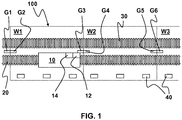
Dem von der Gleisbaumaschine 10 befahrenen Gleisabschnitt 20 ist ein Nebengleis 30 benachbart angeordnet, auf dem der reguläre Zugverkehr erfolgt, der eine Gefährdung für die Baustellenarbeiter darstellt.The
Jeweils einer an der Grenze zwischen aneinandergrenzenden Warnbereichen W1, W2, W3 ist eine Grenzmarkierung G1, G2, G3, G4, G5, G6 angeordnet, die insbesondere als RFID-Transponder G1, G3, G5 und als optisches Zeichen G2, G4, G6 eingerichtet ist. Dabei ist in jedem Warnbereich W1, W2, W3 eine Mehrzahl von dem jeweiligen Warnbereich W1, W2, W3 zugeordneten Warngebern 40 vorgesehen.In each case one on the border between adjoining warning areas W1, W2, W3 a boundary marking G1, G2, G3, G4, G5, G6 is arranged, which in particular as RFID transponder G1, G3, G5 and as an optical character G2, G4, G6 set up is. In this case, in each warning area W1, W2, W3, a plurality of
Die Grenzmarkierung G1, G2, G3, G4, G5, G6 wird von der auf dem Gleisabschnitt 20 fahrenden Gleisbaumaschine 10 beim Eintritt in einen Warnbereich W1 bzw. Übertritt von einem Warnbereich W1, W2 in einen anderen Warnbereich W2, W3 die Grenzmarkierung mittels eines entsprechend geeigneten Sensors 12, 14 erfasst. Insbesondere ist der Sensor 12 als RFID-Lesegerät und der Sensor 14 als optische Kamera ausgebildet.The boundary marking G1, G2, G3, G4, G5, G6 is from the running on the
Durch die vom Sensor 12, 14 erhaltene Information durch Auslesen der Kennung der Warnsystem Grenzmarkierung G1, G2, G3, G4, G5, G6 wird anhand der zuletzt vom Sensor 12, 14 erfassten Grenzmarkierung G1, G2, G3, G4, G5, G6 der aktuelle Warnbereich W1 bestimmt, in dem sich die Gleisbaumaschine 10 befindet. Dabei ist das System so eingerichtet, dass das Warnsignal ausschließlich durch die Warngeber 40, die im aktuellen Warnbereich W1, also dem Warnbereich W1, in dem sich die Gleisbaumaschine 10 aktuell befindet, abgegeben wird. Die anderen Warngeber 40 in den anderen Warnbereichen W2, W3, in denen sich keine Gleisbaumaschine 10 befindet, sind bei Ausgabe eines Warnsignals entsprechend stumm.By the information obtained by the
Claims (8)
Priority Applications (1)
| Application Number | Priority Date | Filing Date | Title |
|---|---|---|---|
| PL18171204T PL3406504T3 (en) | 2017-05-12 | 2018-05-08 | Warning system for a track worksite and method for operating a track worksite |
Applications Claiming Priority (1)
| Application Number | Priority Date | Filing Date | Title |
|---|---|---|---|
| DE102017110417.8A DE102017110417A1 (en) | 2017-05-12 | 2017-05-12 | Warning system for a track construction site and method for operating a track construction site |
Publications (2)
| Publication Number | Publication Date |
|---|---|
| EP3406504A1 true EP3406504A1 (en) | 2018-11-28 |
| EP3406504B1 EP3406504B1 (en) | 2019-07-31 |
Family
ID=62167123
Family Applications (1)
| Application Number | Title | Priority Date | Filing Date |
|---|---|---|---|
| EP18171204.3A Active EP3406504B1 (en) | 2017-05-12 | 2018-05-08 | Warning system for a track worksite and method for operating a track worksite |
Country Status (3)
| Country | Link |
|---|---|
| EP (1) | EP3406504B1 (en) |
| DE (1) | DE102017110417A1 (en) |
| PL (1) | PL3406504T3 (en) |
Cited By (2)
| Publication number | Priority date | Publication date | Assignee | Title |
|---|---|---|---|---|
| AT17200U1 (en) * | 2019-12-16 | 2021-09-15 | Plasser & Theurer Export Von Bahnbaumaschinen Gmbh | Signal box-bound gang warning system |
| EP4249347A1 (en) * | 2022-03-24 | 2023-09-27 | Dual Inventive Holding B.V. | Train warning system for warning trackworkers of the danger of an approaching train on an adjacent track |
Citations (4)
| Publication number | Priority date | Publication date | Assignee | Title |
|---|---|---|---|---|
| DE112005002483T5 (en) * | 2004-10-08 | 2007-09-13 | Recherche Et Developement, Ingenierie S.A.R.L. | System for automatic announcement of trains |
| EP1862367A2 (en) * | 2006-06-01 | 2007-12-05 | ÖBB-Infrastruktur Bau Aktiengesellschaft | Alarm device carrier |
| DE202008008462U1 (en) * | 2008-06-24 | 2008-08-28 | Zöllner GmbH | Arrangement for automatic warning range switching |
| EP2085287A1 (en) * | 2008-01-31 | 2009-08-05 | Schweizer Electronic M2S AG | System for automatically determining and setting warning parameters for track vehicles and corresponding system |
Family Cites Families (2)
| Publication number | Priority date | Publication date | Assignee | Title |
|---|---|---|---|---|
| DE102011017134B4 (en) * | 2011-04-10 | 2014-07-31 | Wilfried Scherf | Arrangement for measuring track sections for the purpose of maintenance of railway tracks |
| DE102014205862A1 (en) * | 2014-03-28 | 2015-10-15 | Siemens Aktiengesellschaft | Method and device for signaling operational processes and technical safety devices on people in the track concerned work related |
-
2017
- 2017-05-12 DE DE102017110417.8A patent/DE102017110417A1/en not_active Withdrawn
-
2018
- 2018-05-08 EP EP18171204.3A patent/EP3406504B1/en active Active
- 2018-05-08 PL PL18171204T patent/PL3406504T3/en unknown
Patent Citations (4)
| Publication number | Priority date | Publication date | Assignee | Title |
|---|---|---|---|---|
| DE112005002483T5 (en) * | 2004-10-08 | 2007-09-13 | Recherche Et Developement, Ingenierie S.A.R.L. | System for automatic announcement of trains |
| EP1862367A2 (en) * | 2006-06-01 | 2007-12-05 | ÖBB-Infrastruktur Bau Aktiengesellschaft | Alarm device carrier |
| EP2085287A1 (en) * | 2008-01-31 | 2009-08-05 | Schweizer Electronic M2S AG | System for automatically determining and setting warning parameters for track vehicles and corresponding system |
| DE202008008462U1 (en) * | 2008-06-24 | 2008-08-28 | Zöllner GmbH | Arrangement for automatic warning range switching |
Cited By (3)
| Publication number | Priority date | Publication date | Assignee | Title |
|---|---|---|---|---|
| AT17200U1 (en) * | 2019-12-16 | 2021-09-15 | Plasser & Theurer Export Von Bahnbaumaschinen Gmbh | Signal box-bound gang warning system |
| EP4249347A1 (en) * | 2022-03-24 | 2023-09-27 | Dual Inventive Holding B.V. | Train warning system for warning trackworkers of the danger of an approaching train on an adjacent track |
| NL2031397B1 (en) * | 2022-03-24 | 2023-10-06 | Dual Inventive Holding B V | Train warning system. |
Also Published As
| Publication number | Publication date |
|---|---|
| PL3406504T3 (en) | 2019-12-31 |
| EP3406504B1 (en) | 2019-07-31 |
| DE102017110417A1 (en) | 2018-11-15 |
Similar Documents
| Publication | Publication Date | Title |
|---|---|---|
| EP2085286B1 (en) | System for automatically determining and setting warning parameters for track vehicles and corresponding system | |
| EP2531391B1 (en) | Method and device for monitoring train integrity | |
| EP4077098A1 (en) | Method and monitoring system for determining a position of a rail vehicle | |
| DE102012107918A1 (en) | Rail vehicle location system for rail vehicle, has digital data base with route data of rail vehicle of traveling track section, where evaluation device is adapted to current location of rail vehicle using current data of ambient sensor | |
| DE102013104088A1 (en) | Method for automatically detecting characteristic elements, in particular a level crossing, and device therefor | |
| EP3406504B1 (en) | Warning system for a track worksite and method for operating a track worksite | |
| DE102014208522A1 (en) | HAZARDOUS AREA MONITORING ON A TRAINER TRANSFER | |
| DE102011106345A1 (en) | Device for validating stretch-side infrastructure elements of railway infrastructure of track, used in rail vehicle, has evaluation unit to determine correlation of data from signal aspect and adapted by infrastructure elements position | |
| EP3401185A2 (en) | Method for allocating a rail vehicle to a warning area and warning system for a track construction site with boundary markings which divide the track construction site into warning areas | |
| DE102017209928A1 (en) | Method for operating a track-bound traffic system | |
| DE102006021040B4 (en) | Method for determining distances between points along a track | |
| DE102021101958B3 (en) | Method and system for determining the distance or the current relative speed of at least two route-bound, in particular rail-bound, mobile objects | |
| EP2230148A1 (en) | Method and system for identifying rail securing devices | |
| DE102006029845B4 (en) | Device and method for securing track sections of a segmented track for a rail-bound vehicle body | |
| EP2439123B1 (en) | Method, apparatus and arrangement for determining information coded in the railway track | |
| EP1972894B1 (en) | Method, computer based device and system for determining a travelled distance | |
| EP3294609B1 (en) | Trackside railway apparatus and method for detecting use of at least one trackside component of a railway installation | |
| DE102008019375A1 (en) | Detector system for use with traffic control system, has detection unit comprising evaluation unit for detecting presence of vehicle based on detection data of loops and antennas, and interface transmitting occupancy data to control system | |
| EP2332804A1 (en) | Testing of waypoints for vehicular ETCS systems | |
| DE102006027676A1 (en) | Identification method for toll required sections of road in electronic tollbooth system, involves assigning line shaped reference object, defined within geo data, to any number of toll required or toll free distance sections | |
| DE102020202394A1 (en) | Hazardous area monitoring method and system therefor | |
| EP2674345B1 (en) | Device for detecting conditions on track sections | |
| DE2711572C3 (en) | Device for securing the location for route-bound vehicles | |
| EP2809563B1 (en) | Shunting conveyor system and conveyor wagon for such a system | |
| EP2124358B1 (en) | Device and method for wireless punctiform data transfer |
Legal Events
| Date | Code | Title | Description |
|---|---|---|---|
| PUAI | Public reference made under article 153(3) epc to a published international application that has entered the european phase |
Free format text: ORIGINAL CODE: 0009012 |
|
| STAA | Information on the status of an ep patent application or granted ep patent |
Free format text: STATUS: THE APPLICATION HAS BEEN PUBLISHED |
|
| AK | Designated contracting states |
Kind code of ref document: A1 Designated state(s): AL AT BE BG CH CY CZ DE DK EE ES FI FR GB GR HR HU IE IS IT LI LT LU LV MC MK MT NL NO PL PT RO RS SE SI SK SM TR |
|
| AX | Request for extension of the european patent |
Extension state: BA ME |
|
| STAA | Information on the status of an ep patent application or granted ep patent |
Free format text: STATUS: REQUEST FOR EXAMINATION WAS MADE |
|
| 17P | Request for examination filed |
Effective date: 20190204 |
|
| RBV | Designated contracting states (corrected) |
Designated state(s): AL AT BE BG CH CY CZ DE DK EE ES FI FR GB GR HR HU IE IS IT LI LT LU LV MC MK MT NL NO PL PT RO RS SE SI SK SM TR |
|
| GRAP | Despatch of communication of intention to grant a patent |
Free format text: ORIGINAL CODE: EPIDOSNIGR1 |
|
| STAA | Information on the status of an ep patent application or granted ep patent |
Free format text: STATUS: GRANT OF PATENT IS INTENDED |
|
| GRAS | Grant fee paid |
Free format text: ORIGINAL CODE: EPIDOSNIGR3 |
|
| GRAA | (expected) grant |
Free format text: ORIGINAL CODE: 0009210 |
|
| STAA | Information on the status of an ep patent application or granted ep patent |
Free format text: STATUS: THE PATENT HAS BEEN GRANTED |
|
| INTG | Intention to grant announced |
Effective date: 20190604 |
|
| AK | Designated contracting states |
Kind code of ref document: B1 Designated state(s): AL AT BE BG CH CY CZ DE DK EE ES FI FR GB GR HR HU IE IS IT LI LT LU LV MC MK MT NL NO PL PT RO RS SE SI SK SM TR |
|
| REG | Reference to a national code |
Ref country code: CH Ref legal event code: EP Ref country code: GB Ref legal event code: FG4D Free format text: NOT ENGLISH |
|
| REG | Reference to a national code |
Ref country code: AT Ref legal event code: REF Ref document number: 1160580 Country of ref document: AT Kind code of ref document: T Effective date: 20190815 |
|
| REG | Reference to a national code |
Ref country code: DE Ref legal event code: R082 Ref document number: 502018000112 Country of ref document: DE Representative=s name: LBMR. PATENT- UND MARKENRECHT, DE |
|
| REG | Reference to a national code |
Ref country code: IE Ref legal event code: FG4D Free format text: LANGUAGE OF EP DOCUMENT: GERMAN |
|
| REG | Reference to a national code |
Ref country code: DE Ref legal event code: R096 Ref document number: 502018000112 Country of ref document: DE |
|
| REG | Reference to a national code |
Ref country code: CH Ref legal event code: NV Representative=s name: ISLER AND PEDRAZZINI AG, CH |
|
| REG | Reference to a national code |
Ref country code: NL Ref legal event code: MP Effective date: 20190731 |
|
| REG | Reference to a national code |
Ref country code: LT Ref legal event code: MG4D |
|
| PG25 | Lapsed in a contracting state [announced via postgrant information from national office to epo] |
Ref country code: PT Free format text: LAPSE BECAUSE OF FAILURE TO SUBMIT A TRANSLATION OF THE DESCRIPTION OR TO PAY THE FEE WITHIN THE PRESCRIBED TIME-LIMIT Effective date: 20191202 Ref country code: HR Free format text: LAPSE BECAUSE OF FAILURE TO SUBMIT A TRANSLATION OF THE DESCRIPTION OR TO PAY THE FEE WITHIN THE PRESCRIBED TIME-LIMIT Effective date: 20190731 Ref country code: LT Free format text: LAPSE BECAUSE OF FAILURE TO SUBMIT A TRANSLATION OF THE DESCRIPTION OR TO PAY THE FEE WITHIN THE PRESCRIBED TIME-LIMIT Effective date: 20190731 Ref country code: SE Free format text: LAPSE BECAUSE OF FAILURE TO SUBMIT A TRANSLATION OF THE DESCRIPTION OR TO PAY THE FEE WITHIN THE PRESCRIBED TIME-LIMIT Effective date: 20190731 Ref country code: NL Free format text: LAPSE BECAUSE OF FAILURE TO SUBMIT A TRANSLATION OF THE DESCRIPTION OR TO PAY THE FEE WITHIN THE PRESCRIBED TIME-LIMIT Effective date: 20190731 Ref country code: BG Free format text: LAPSE BECAUSE OF FAILURE TO SUBMIT A TRANSLATION OF THE DESCRIPTION OR TO PAY THE FEE WITHIN THE PRESCRIBED TIME-LIMIT Effective date: 20191031 Ref country code: FI Free format text: LAPSE BECAUSE OF FAILURE TO SUBMIT A TRANSLATION OF THE DESCRIPTION OR TO PAY THE FEE WITHIN THE PRESCRIBED TIME-LIMIT Effective date: 20190731 Ref country code: NO Free format text: LAPSE BECAUSE OF FAILURE TO SUBMIT A TRANSLATION OF THE DESCRIPTION OR TO PAY THE FEE WITHIN THE PRESCRIBED TIME-LIMIT Effective date: 20191031 |
|
| PG25 | Lapsed in a contracting state [announced via postgrant information from national office to epo] |
Ref country code: RS Free format text: LAPSE BECAUSE OF FAILURE TO SUBMIT A TRANSLATION OF THE DESCRIPTION OR TO PAY THE FEE WITHIN THE PRESCRIBED TIME-LIMIT Effective date: 20190731 Ref country code: LV Free format text: LAPSE BECAUSE OF FAILURE TO SUBMIT A TRANSLATION OF THE DESCRIPTION OR TO PAY THE FEE WITHIN THE PRESCRIBED TIME-LIMIT Effective date: 20190731 Ref country code: GR Free format text: LAPSE BECAUSE OF FAILURE TO SUBMIT A TRANSLATION OF THE DESCRIPTION OR TO PAY THE FEE WITHIN THE PRESCRIBED TIME-LIMIT Effective date: 20191101 Ref country code: ES Free format text: LAPSE BECAUSE OF FAILURE TO SUBMIT A TRANSLATION OF THE DESCRIPTION OR TO PAY THE FEE WITHIN THE PRESCRIBED TIME-LIMIT Effective date: 20190731 Ref country code: AL Free format text: LAPSE BECAUSE OF FAILURE TO SUBMIT A TRANSLATION OF THE DESCRIPTION OR TO PAY THE FEE WITHIN THE PRESCRIBED TIME-LIMIT Effective date: 20190731 Ref country code: IS Free format text: LAPSE BECAUSE OF FAILURE TO SUBMIT A TRANSLATION OF THE DESCRIPTION OR TO PAY THE FEE WITHIN THE PRESCRIBED TIME-LIMIT Effective date: 20191130 |
|
| PG25 | Lapsed in a contracting state [announced via postgrant information from national office to epo] |
Ref country code: TR Free format text: LAPSE BECAUSE OF FAILURE TO SUBMIT A TRANSLATION OF THE DESCRIPTION OR TO PAY THE FEE WITHIN THE PRESCRIBED TIME-LIMIT Effective date: 20190731 |
|
| PG25 | Lapsed in a contracting state [announced via postgrant information from national office to epo] |
Ref country code: RO Free format text: LAPSE BECAUSE OF FAILURE TO SUBMIT A TRANSLATION OF THE DESCRIPTION OR TO PAY THE FEE WITHIN THE PRESCRIBED TIME-LIMIT Effective date: 20190731 Ref country code: EE Free format text: LAPSE BECAUSE OF FAILURE TO SUBMIT A TRANSLATION OF THE DESCRIPTION OR TO PAY THE FEE WITHIN THE PRESCRIBED TIME-LIMIT Effective date: 20190731 Ref country code: DK Free format text: LAPSE BECAUSE OF FAILURE TO SUBMIT A TRANSLATION OF THE DESCRIPTION OR TO PAY THE FEE WITHIN THE PRESCRIBED TIME-LIMIT Effective date: 20190731 |
|
| PG25 | Lapsed in a contracting state [announced via postgrant information from national office to epo] |
Ref country code: SM Free format text: LAPSE BECAUSE OF FAILURE TO SUBMIT A TRANSLATION OF THE DESCRIPTION OR TO PAY THE FEE WITHIN THE PRESCRIBED TIME-LIMIT Effective date: 20190731 Ref country code: IS Free format text: LAPSE BECAUSE OF FAILURE TO SUBMIT A TRANSLATION OF THE DESCRIPTION OR TO PAY THE FEE WITHIN THE PRESCRIBED TIME-LIMIT Effective date: 20200224 Ref country code: SK Free format text: LAPSE BECAUSE OF FAILURE TO SUBMIT A TRANSLATION OF THE DESCRIPTION OR TO PAY THE FEE WITHIN THE PRESCRIBED TIME-LIMIT Effective date: 20190731 Ref country code: CZ Free format text: LAPSE BECAUSE OF FAILURE TO SUBMIT A TRANSLATION OF THE DESCRIPTION OR TO PAY THE FEE WITHIN THE PRESCRIBED TIME-LIMIT Effective date: 20190731 |
|
| REG | Reference to a national code |
Ref country code: DE Ref legal event code: R097 Ref document number: 502018000112 Country of ref document: DE |
|
| PLBE | No opposition filed within time limit |
Free format text: ORIGINAL CODE: 0009261 |
|
| STAA | Information on the status of an ep patent application or granted ep patent |
Free format text: STATUS: NO OPPOSITION FILED WITHIN TIME LIMIT |
|
| PG2D | Information on lapse in contracting state deleted |
Ref country code: IS |
|
| PG25 | Lapsed in a contracting state [announced via postgrant information from national office to epo] |
Ref country code: IS Free format text: LAPSE BECAUSE OF FAILURE TO SUBMIT A TRANSLATION OF THE DESCRIPTION OR TO PAY THE FEE WITHIN THE PRESCRIBED TIME-LIMIT Effective date: 20191030 |
|
| 26N | No opposition filed |
Effective date: 20200603 |
|
| PG25 | Lapsed in a contracting state [announced via postgrant information from national office to epo] |
Ref country code: MC Free format text: LAPSE BECAUSE OF FAILURE TO SUBMIT A TRANSLATION OF THE DESCRIPTION OR TO PAY THE FEE WITHIN THE PRESCRIBED TIME-LIMIT Effective date: 20190731 |
|
| REG | Reference to a national code |
Ref country code: BE Ref legal event code: MM Effective date: 20200531 |
|
| PG25 | Lapsed in a contracting state [announced via postgrant information from national office to epo] |
Ref country code: LU Free format text: LAPSE BECAUSE OF NON-PAYMENT OF DUE FEES Effective date: 20200508 |
|
| PG25 | Lapsed in a contracting state [announced via postgrant information from national office to epo] |
Ref country code: IE Free format text: LAPSE BECAUSE OF NON-PAYMENT OF DUE FEES Effective date: 20200508 |
|
| PG25 | Lapsed in a contracting state [announced via postgrant information from national office to epo] |
Ref country code: BE Free format text: LAPSE BECAUSE OF NON-PAYMENT OF DUE FEES Effective date: 20200531 |
|
| PG25 | Lapsed in a contracting state [announced via postgrant information from national office to epo] |
Ref country code: MT Free format text: LAPSE BECAUSE OF FAILURE TO SUBMIT A TRANSLATION OF THE DESCRIPTION OR TO PAY THE FEE WITHIN THE PRESCRIBED TIME-LIMIT Effective date: 20190731 Ref country code: CY Free format text: LAPSE BECAUSE OF FAILURE TO SUBMIT A TRANSLATION OF THE DESCRIPTION OR TO PAY THE FEE WITHIN THE PRESCRIBED TIME-LIMIT Effective date: 20190731 |
|
| PG25 | Lapsed in a contracting state [announced via postgrant information from national office to epo] |
Ref country code: MK Free format text: LAPSE BECAUSE OF FAILURE TO SUBMIT A TRANSLATION OF THE DESCRIPTION OR TO PAY THE FEE WITHIN THE PRESCRIBED TIME-LIMIT Effective date: 20190731 |
|
| PGFP | Annual fee paid to national office [announced via postgrant information from national office to epo] |
Ref country code: IT Payment date: 20230526 Year of fee payment: 6 Ref country code: FR Payment date: 20230526 Year of fee payment: 6 Ref country code: DE Payment date: 20230210 Year of fee payment: 6 Ref country code: CH Payment date: 20230605 Year of fee payment: 6 |
|
| PGFP | Annual fee paid to national office [announced via postgrant information from national office to epo] |
Ref country code: PL Payment date: 20230419 Year of fee payment: 6 Ref country code: AT Payment date: 20230522 Year of fee payment: 6 |
|
| PG25 | Lapsed in a contracting state [announced via postgrant information from national office to epo] |
Ref country code: SI Free format text: LAPSE BECAUSE OF FAILURE TO SUBMIT A TRANSLATION OF THE DESCRIPTION OR TO PAY THE FEE WITHIN THE PRESCRIBED TIME-LIMIT Effective date: 20190731 |
|
| PGFP | Annual fee paid to national office [announced via postgrant information from national office to epo] |
Ref country code: GB Payment date: 20230524 Year of fee payment: 6 |