EP3406399A1 - Coolant supply device - Google Patents
Coolant supply device Download PDFInfo
- Publication number
- EP3406399A1 EP3406399A1 EP18173620.8A EP18173620A EP3406399A1 EP 3406399 A1 EP3406399 A1 EP 3406399A1 EP 18173620 A EP18173620 A EP 18173620A EP 3406399 A1 EP3406399 A1 EP 3406399A1
- Authority
- EP
- European Patent Office
- Prior art keywords
- coolant
- reservoir
- flow
- communicating part
- coolant reservoir
- Prior art date
- Legal status (The legal status is an assumption and is not a legal conclusion. Google has not performed a legal analysis and makes no representation as to the accuracy of the status listed.)
- Granted
Links
Images

Classifications
-
- B—PERFORMING OPERATIONS; TRANSPORTING
- B23—MACHINE TOOLS; METAL-WORKING NOT OTHERWISE PROVIDED FOR
- B23Q—DETAILS, COMPONENTS, OR ACCESSORIES FOR MACHINE TOOLS, e.g. ARRANGEMENTS FOR COPYING OR CONTROLLING; MACHINE TOOLS IN GENERAL CHARACTERISED BY THE CONSTRUCTION OF PARTICULAR DETAILS OR COMPONENTS; COMBINATIONS OR ASSOCIATIONS OF METAL-WORKING MACHINES, NOT DIRECTED TO A PARTICULAR RESULT
- B23Q11/00—Accessories fitted to machine tools for keeping tools or parts of the machine in good working condition or for cooling work; Safety devices specially combined with or arranged in, or specially adapted for use in connection with, machine tools
- B23Q11/10—Arrangements for cooling or lubricating tools or work
- B23Q11/1069—Filtration systems specially adapted for cutting liquids
-
- F—MECHANICAL ENGINEERING; LIGHTING; HEATING; WEAPONS; BLASTING
- F28—HEAT EXCHANGE IN GENERAL
- F28D—HEAT-EXCHANGE APPARATUS, NOT PROVIDED FOR IN ANOTHER SUBCLASS, IN WHICH THE HEAT-EXCHANGE MEDIA DO NOT COME INTO DIRECT CONTACT
- F28D21/00—Heat-exchange apparatus not covered by any of the groups F28D1/00 - F28D20/00
- F28D21/0017—Flooded core heat exchangers
-
- B—PERFORMING OPERATIONS; TRANSPORTING
- B23—MACHINE TOOLS; METAL-WORKING NOT OTHERWISE PROVIDED FOR
- B23Q—DETAILS, COMPONENTS, OR ACCESSORIES FOR MACHINE TOOLS, e.g. ARRANGEMENTS FOR COPYING OR CONTROLLING; MACHINE TOOLS IN GENERAL CHARACTERISED BY THE CONSTRUCTION OF PARTICULAR DETAILS OR COMPONENTS; COMBINATIONS OR ASSOCIATIONS OF METAL-WORKING MACHINES, NOT DIRECTED TO A PARTICULAR RESULT
- B23Q11/00—Accessories fitted to machine tools for keeping tools or parts of the machine in good working condition or for cooling work; Safety devices specially combined with or arranged in, or specially adapted for use in connection with, machine tools
- B23Q11/10—Arrangements for cooling or lubricating tools or work
-
- B—PERFORMING OPERATIONS; TRANSPORTING
- B24—GRINDING; POLISHING
- B24B—MACHINES, DEVICES, OR PROCESSES FOR GRINDING OR POLISHING; DRESSING OR CONDITIONING OF ABRADING SURFACES; FEEDING OF GRINDING, POLISHING, OR LAPPING AGENTS
- B24B55/00—Safety devices for grinding or polishing machines; Accessories fitted to grinding or polishing machines for keeping tools or parts of the machine in good working condition
- B24B55/02—Equipment for cooling the grinding surfaces, e.g. devices for feeding coolant
- B24B55/03—Equipment for cooling the grinding surfaces, e.g. devices for feeding coolant designed as a complete equipment for feeding or clarifying coolant
-
- F—MECHANICAL ENGINEERING; LIGHTING; HEATING; WEAPONS; BLASTING
- F28—HEAT EXCHANGE IN GENERAL
- F28F—DETAILS OF HEAT-EXCHANGE AND HEAT-TRANSFER APPARATUS, OF GENERAL APPLICATION
- F28F13/00—Arrangements for modifying heat-transfer, e.g. increasing, decreasing
- F28F13/06—Arrangements for modifying heat-transfer, e.g. increasing, decreasing by affecting the pattern of flow of the heat-exchange media
-
- F—MECHANICAL ENGINEERING; LIGHTING; HEATING; WEAPONS; BLASTING
- F28—HEAT EXCHANGE IN GENERAL
- F28D—HEAT-EXCHANGE APPARATUS, NOT PROVIDED FOR IN ANOTHER SUBCLASS, IN WHICH THE HEAT-EXCHANGE MEDIA DO NOT COME INTO DIRECT CONTACT
- F28D21/00—Heat-exchange apparatus not covered by any of the groups F28D1/00 - F28D20/00
- F28D2021/0019—Other heat exchangers for particular applications; Heat exchange systems not otherwise provided for
- F28D2021/004—Other heat exchangers for particular applications; Heat exchange systems not otherwise provided for for engine or machine cooling systems
-
- F—MECHANICAL ENGINEERING; LIGHTING; HEATING; WEAPONS; BLASTING
- F28—HEAT EXCHANGE IN GENERAL
- F28F—DETAILS OF HEAT-EXCHANGE AND HEAT-TRANSFER APPARATUS, OF GENERAL APPLICATION
- F28F2250/00—Arrangements for modifying the flow of the heat exchange media, e.g. flow guiding means; Particular flow patterns
- F28F2250/08—Fluid driving means, e.g. pumps, fans
-
- F—MECHANICAL ENGINEERING; LIGHTING; HEATING; WEAPONS; BLASTING
- F28—HEAT EXCHANGE IN GENERAL
- F28F—DETAILS OF HEAT-EXCHANGE AND HEAT-TRANSFER APPARATUS, OF GENERAL APPLICATION
- F28F2250/00—Arrangements for modifying the flow of the heat exchange media, e.g. flow guiding means; Particular flow patterns
- F28F2250/10—Particular pattern of flow of the heat exchange media
- F28F2250/102—Particular pattern of flow of the heat exchange media with change of flow direction
Definitions
- the present invention relates to a coolant supply device supplying coolant to a predetermined destination, such as a machining area of a machine tool or the like.
- a coolant processing device which is configured to supply coolant into a machining area of a machine tool and separate chips and the like from coolant returned from the machine tool (Patent Literature 1 listed below).
- This coolant processing device is configured to include a dirty reservoir receiving chips and coolant exhausted from the machine tool, a filtering drum immersed in coolant in the dirty reservoir and filtering the coolant in the process of taking in the coolant, a first coolant reservoir disposed to be connected to a first side surface of the dirty reservoir and having a path communicating with an internal space of the filtering drum through an opening formed in the first side surface of the dirty reservoir, a second coolant reservoir disposed on a second side surface side of the dirty reservoir and surrounded by a sidewall, a connecting path communicating with the first coolant reservoir and the second coolant reservoir, and a pump disposed away from the sidewall of the second coolant reservoir and near the center of the second coolant reservoir in plan view and pumping up coolant from the second coolant reservoir and supplying the coolant to the machine tool.
- a rear sidewall surface of the connecting path extends from a rear sidewall surface of the second coolant reservoir, and a portion of the sidewall of the second coolant reservoir which extends from the rear side to the dirty reservoir side through the front side thereof is formed by a continuous surface including a concave surface.
- the first coolant reservoir, the second coolant reservoir, and the connecting path together constitute a coolant tank.
- Patent Literature 1 Japanese Unexamined Patent Application Publication No. 2009-226491
- the above-described conventional coolant processing device produces a flow of a coolant flowing from the first coolant reservoir toward the second coolant reservoir by virtue of the action of pumping up coolant with the pump and the action of returning coolant from the machine tool to the device. Therefore, except for a case where the pump has a very high pump-up ability, in a case where the pump has a pump-up ability typically required in a machine tool, a liquid flow with a flow velocity sufficient to suppress deposition and accumulation of chips, sludge, and the like cannot be produced in the first coolant reservoir, the second coolant reservoir, and the connecting path,.
- the present invention has been achieved in view of the above-described circumstances, and an object thereof is to provide a coolant supply device which can produce a liquid flow with a sufficient flow velocity in a coolant tank to suppress deposition and accumulation of foreign substances in the coolant tank.
- the present invention for solving the above-described problems, relates to a coolant supply device, including:
- coolant in the second coolant reservoir is pumped up and supplied to a predetermined destination, for example, a machining area of a machine tool, by the supply pump.
- the supplied coolant with which foreign substances, such as chips, sludge, and the like mixed in, is returned to the first coolant reservoir through a predetermined flow path.
- the coolant retuned to the first coolant reservoir flows into the second coolant reservoir through the communicating part.
- the first coolant reservoir has the first agitating nozzle body provided therein, and coolant in the coolant tank is supplied to the first agitating nozzle body by the agitation pump and the supplied coolant is discharged from the first agitating nozzle body.
- the coolant discharged from the first agitating nozzle body assists a flow of coolant flowing toward the communicating part, thereby agitating coolant in the first coolant reservoir and increasing the velocity of a flow of coolant flowing through the communicating part.
- the action of agitating coolant in the first coolant reservoir and the action of accelerating coolant in the communicating part suppress deposition and accumulation of foreign substances in the first coolant reservoir and in the communicating part.
- the second coolant reservoir has the second agitating nozzle body provided therein, and coolant is supplied also to the second agitating nozzle body by the agitation pump and the supplied coolant is discharged from the second agitating nozzle body.
- the coolant discharged from the second agitating nozzle body assists a flow of coolant flowing into the second coolant reservoir from the communicating part, thereby agitating coolant in the second coolant reservoir. This action of agitating coolant suppresses deposition and accumulation of foreign substances in the second coolant reservoir.
- coolant discharged from the first agitating nozzle body and coolant discharged from the second agitating nozzle body agitate coolant in the first coolant reservoir and in the second coolant reservoir, and accelerate the flow of coolant flowing through the communicating part, which can suppress deposition and accumulation of foreign substances in the first and second coolant reservoirs and in the communicating part.
- At least one of the first and second agitating nozzle bodies has a plurality of discharge ports and a discharge direction of at least one of the plurality of discharge ports is directed more centrally of a corresponding coolant reservoir than a discharge direction of a remaining discharge port.
- first and second coolant reservoirs In a case where either one of the first and second coolant reservoirs is susceptible to deposition and accumulation of foreign substances, a configuration can be employed in which a corresponding one of the first and second agitating nozzle bodies has a plurality of discharge ports. Conversely, in a case where both of the first and second coolant reservoirs are susceptible to deposition and accumulation of foreign substances, a configuration can be employed in which both of the first and second agitating nozzle bodies have a plurality of discharge ports.
- the second coolant reservoir may have a baffle plate disposed therein at a position ahead in the coolant discharge direction of the second agitating nozzle body. It is preferred that the baffle plate extends inward from an inner wall of the second coolant reservoir to obstruct the flow of coolant, with a clearance between the baffle plate and a bottom of the second coolant reservoir such that the coolant can flow through the clearance.
- the coolant discharged from the discharge port of the second agitating nozzle body assists a liquid flow and forms a swirl flow (vortex flow) swirling along the wall of the reservoir. Accordingly, the velocity of the flow of coolant is smallest at a position remote from the second agitating nozzle body, that is, at a position ahead of the second agitating nozzle body, and therefore the position is susceptible to deposition and accumulation of foreign substances.
- the baffle plate is provided at the position ahead of the second agitating nozzle body at which the velocity of the flow of coolant is smallest, the flow of coolant flowing ahead from the second agitating nozzle body is obstructed by the baffle plate, and this causes the flow of coolant to flow through the clearance between the baffle plate and the bottom of the second coolant reservoir.
- the flow path of the coolant being thus narrowed by the baffle plate increases the velocity of the flow of coolant flowing through the clearance, thereby preventing deposition and accumulation of foreign substances at the clearance.
- the second coolant reservoir has a flow adjusting plate disposed therein which extends from the communicating part along an inner wall surface of the second coolant reservoir and faces the inner wall surface to adjust the flow of coolant flowing into the second coolant reservoir from the communicating part.
- the coolant discharged from the discharge port of the second agitating nozzle body assists a coolant flow and forms a swirl flow swirling along the wall of the reservoir. Therefore, at the connecting portion between the communicating part and the second coolant reservoir, the flow of coolant flowing into the second coolant reservoir from the communicating part collides with the swirling flow of coolant in the second coolant reservoir and thereby is blocked, which makes the communicating part susceptible to deposition and accumulation of foreign substances.
- the provision of the flow adjusting plate allows the flow of coolant flowing into the second coolant reservoir from the communicating part and the swirl flow of coolant in the second coolant reservoir to join together smoothly at the connecting portion between the communicating part and the second coolant reservoir, so that the flow of coolant flowing from the communicating part successfully flows into the second coolant reservoir. Thereby, deposition and accumulation of foreign substances in the communicating part are prevented.
- coolant discharged from the first agitating nozzle body and coolant discharged from the second agitating nozzle body agitate coolant in the first coolant reservoir and in the second coolant reservoir and accelerate a flow of coolant flowing through the communicating part. Therefore, the coolant supply device according to the present invention can suppress deposition and accumulation of foreign substances in the first and second coolant reservoirs and in the communicating part.
- a coolant supply device 1 is attached to a machine tool, which is not shown in the drawings, to supply coolant C to a machining area and the like of the machine tool.
- the coolant supply device 1 includes a coolant tank 2 which is formed to have a substantially U-shaped overall shape in plan view and stores coolant C therein.
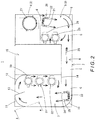
- the coolant tank 2 includes a first coolant reservoir 3 and a second coolant reservoir 7 each having a rectangular shape in plan view and arranged in parallel with a predetermined space therebetween, as well as a communicating part 8 arranged between ends (ends illustrated on the lower side in Fig. 2 ) of the first coolant reservoir 3 and second coolant reservoir 7 and having one end connected to a sidewall of the first coolant reservoir 3 and another end connected to a sidewall of the second coolant reservoir 7 to allow the first coolant reservoir 3 and the second coolant reservoir 7 to communicate with each other.
- the first coolant reservoir 3 is liquid-tightly divided into two reservoirs by a divider 6; the upper reservoir in Fig. 2 being a highly clean reservoir 4 and the lower reservoir in Fig. 2 being a return reservoir 5.
- the return reservoir 5 has a flow adjusting plate 9 disposed at the lower right corner thereof in Fig. 2
- the second coolant reservoir 7 has flow adjusting plates 10, 11, 12 disposed at corners thereof.
- Each of the flow adjusting plates 9, 10, 11, 12 is folded to be multifaceted, thereby being formed in a substantially arc shape.
- the highly clean reservoir 4 has a first pump 27 disposed therein, and the return reservoir 5 has a second pump 28 and a third pump 29 disposed therein near a sidewall thereof located on the second coolant reservoir 7 side. Further, the return reservoir 5 has a first agitating nozzle body 20 disposed therein at a position diagonal to the connecting portion between the communicating part 8 and the return reservoir 5. Furthermore, the second coolant reservoir 7 has a second agitating nozzle body 23 disposed therein at a position facing the connecting portion between the communicating part 8 and the second coolant reservoir 7, and has a fourth pump 30, a fifth pump 31, and a sixth pump 32 disposed therein near a sidewall thereof located on the first coolant reservoir 3 side. Further, the communicating part 8 has a third agitating nozzle body 26 disposed therein. Note that the first agitating nozzle body 20, the second agitating nozzle body 23, and the third agitating nozzle body 26 are being immersed in coolant C.
- the first pump 27 pumps up coolant C from the highly clean reservoir 4 and supplies the pumped-up coolant C to a circulating path formed in a spindle of the machine tool.
- the second pump 28 pumps up coolant C from the return reservoir 5 and supplies the pumped-up coolant C to the first agitating nozzle body 20, the second agitating nozzle body 23, and the third agitating nozzle body 26.
- the third pump 29 pumps up coolant C from the return reservoir 5 and supplies the pumped-up coolant C to a destination above the machining area of the machine tool to discharge the coolant C into the machining area.
- the fourth pump 30, the fifth pump 31, and the sixth pump 32 each pump up coolant C from the second coolant reservoir 7, the fourth pump 30 supplies the pumped-up coolant C to a filter device, which is not shown in the drawings, the fifth pump 31 supplies the pumped-up coolant C to a destination near the spindle of the machine tool to discharge the coolant C into the machining area, and the sixth pump 32 supplies the pumped-up coolant C to a base of the machine tool.
- the first pump 27 is mounted on a mounting plate (not shown) that constitutes a top plate of the highly clean reservoir 4
- the second pump 28, the third pump 29, the fourth pump 30, the fifth pump 31, and the sixth pump 32 are mounted on a top plate (not shown) closing the coolant tank 2.
- a chip conveyor (not shown) as disclosed in Patent Literature 1 mentioned above is disposed in the space between the first coolant reservoir 3 and the second coolant reservoir 7 of the coolant tank 2. This chip conveyor collects the coolant C supplied to the machining area of the machine tool, with chips and sludge contained in the coolant C.
- the chip conveyor has incorporated therein a drum-shaped filter (drum filter) (not shown) as disposed in Patent Literature 1 mentioned above.
- drum filter drum filter
- the internal space of the drum filter liquid-tightly communicates with the coolant tank 2 through an opening (not shown) formed in the sidewall of the return reservoir 5 located on the second coolant reservoir 7 side. Accordingly, the coolant C supplied to the machining area of the machine tool is collected in the chip conveyor, and filtered by the drum filter, after which the coolant C is returned to the return reservoir 5.
- the coolant C supplied to the circulating path of the spindle by the first pump 27 and the coolant C supplied to the base of the machine tool by the sixth pump 32 are returned to the return reservoir 5 through separate flow paths. Further, the coolant C pumped up by the sixth pump 32 is used also for so-called backwash for unclogging the drum filter. Further, the coolant C pumped up by the fourth pump 30 is, as described above, supplied to the not-shown filter device, and highly purged by the filter device, after which the coolant C is supplied to the highly clean reservoir 4. If an excessive amount of coolant C is supplied to the highly clean reservoir 4, the coolant C overflows into the return reservoir 5 through an opening 6a formed in the divider 6.
- the first agitating nozzle body 20 includes two nozzles 21, 22 arranged in parallel and discharging the coolant C supplied by the second pump 28 toward the communicating part 8.
- the coolant C discharged from the nozzle 22 produces a liquid flow which flows substantially along sidewalls of the return reservoir 5, while the coolant C discharged from the nozzle 21 produces a liquid flow which is directed approximately to the center of the return reservoir 5.
- the third agitating nozzle body 26 is disposed so as to discharge the coolant C supplied by the second pump 28 toward the second coolant reservoir 7.
- the second agitating nozzle body 23 includes two nozzles 24, 25 arranged in parallel and discharging the coolant C supplied by the second pump 28 in a direction substantially perpendicular to a flow of coolant C flowing into the second coolant reservoir 7 from the communicating part 8, that is, in the upward direction in Fig. 2 .
- the coolant C discharged from the nozzle 25 produces a liquid flow which flows substantially along sidewalls of the second coolant reservoir 7, while the coolant C discharged from the nozzle 24 produces a liquid flow which is directed approximately to the center of the second coolant reservoir 7.
- the second coolant reservoir 7 has a baffle plate 13 disposed therein at a position ahead in the direction of the discharge of coolant C from the second agitating nozzle body 23.
- the baffle plate 13, as shown in Fig. 2 extends inward from an inner wall of the second coolant reservoir 7 to obstruct the flow of coolant C.
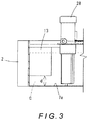
- a clearance is formed with a distance d between the baffle plate 13 and a bottom 7a of the second coolant reservoir 7, through which clearance coolant C can flow.
- the second coolant reservoir 7 has a flow adjusting plate 14 disposed therein at the connecting portion between the communicating part 8 and the second coolant reservoir 7, the flow adjusting plate 14 extending from the communicating part 8 along an inner wall surface (inner wall surface illustrated on the lower side in Fig. 2 ) of the second coolant reservoir 7 that continues from the communicating part 8, and facing the inner wall surface.
- coolant C in the second coolant reservoir 7 is pumped up by the fourth pump 30, the fifth pump 31, and the sixth pump 32, the pumped-up coolant C is supplied to the above-mentioned destinations, and the supplied coolant C is returned to the return reservoir 5.
- this circulation of coolant C forms a basic flow of coolant C that flows from the reservoir 5 into the second coolant reservoir 7 through the communicating part 8.
- coolant C from the machining area of the machine tool is returned to the return reservoir 5 via the chip conveyor. Further, coolant C supplied to the circulating path of the spindle by the first pump 27 is returned to the return reservoir 5 through an appropriate flow path, and coolant C supplied to the base of the machine tool by the sixth pump 32 is also returned to the return reservoir 5 through an appropriate flow path. Furthermore, coolant C supplied to the highly clean reservoir 4 by the fifth pump 31 overflows into the return reservoir 5. In the return reservoir 5, such coolant C produces a liquid flow which flows toward the communicating part 8, and therefore the coolant C flows from the return reservoir 5 into the second coolant reservoir 7 through the communicating part 8.
- coolant C is pumped up by the fourth pump 30, the fifth pump 31, and the sixth pump 32, and their pumping-up actions and the flow of coolant C flowing into the second coolant reservoir 7 from the communicating part 8 produce a swirl flow.
- the nozzles 21, 22 of the first agitating nozzle body 20 discharge coolant C supplied thereto by the second pump 28, the coolant C discharged from the nozzle 22 produces a liquid flow which flows substantially along the sidewalls of the return reservoir 5, and the coolant C discharged from the nozzle 21 produces a liquid flow which is directed approximately to the center of the return reservoir 5.
- the flow of coolant C flowing toward the communicating part 8 is assisted by the coolant C discharged from the nozzles 21, 22 and the coolant C in the return reservoir 5 is agitated.
- the arc-shaped flow adjusting plate 9 disposed at the corner of the return reservoir 5 enables a stagnation-free, smooth flow of coolant C at the corner.
- coolant C is discharged from the third agitating nozzle body 26 toward the second coolant reservoir 7. Therefore, the coolant C flowing into the second coolant reservoir 7 from the return reservoir 5 is assisted and accelerated by the coolant C discharged from the third agitating nozzle body 26 and this coolant C flows into the second coolant reservoir 7. Thereby, deposition and accumulation of foreign substances in the communicating part 8 can be suppressed.
- the nozzles 24, 25 of the second agitating nozzle body 23 discharge coolant C supplied thereto by the second pump 28, the coolant C discharged from the nozzle 25 produces a liquid flow which flows substantially along the sidewalls of the second coolant reservoir 7, and the coolant discharged from the nozzle 24 produces a liquid flow which is directed approximately to the center of the second coolant reservoir 7.
- the flow (swirl flow) of coolant C in the second coolant reservoir 7 is assisted and agitated by the coolant C discharged from the nozzles 24, 25.
- the arc-shaped flow adjusting plates 10, 11, 12 disposed at the corners of the second coolant reservoir 7 enable a stagnation-free, smooth flow of coolant C at the corners.
- the velocity of the swirl flow formed in the second coolant reservoir 7 is smallest at a position remote from the second agitating nozzle body 23, that is, at a position ahead in the discharge direction of the second agitating nozzle body 23. In the flow path following the position, the flow velocity is increased by the pump-up actions of the fourth pump 30, fifth pump 31, and sixth pump 32.
- the baffle plate 13 is provided at a position at which the velocity of the flow of coolant C is small; the action of the baffle plate 13 can increase the velocity of the flow of coolant C. That is, the flow of coolant C flowing ahead from the second agitating nozzle body 23 is obstructed by the baffle plate 13, and this causes the flow of coolant C to flow through the clearance formed between the baffle plate 13 and the bottom 7a of the second coolant reservoir 7 shown in Fig. 3 . The flow path of the coolant C being thus narrowed by the baffle plate 13 increases the velocity of the flow of coolant C flowing through the clearance.
- the flow of coolant therein is assisted by the coolant discharged from the second agitating nozzle body 23 and thereby the coolant therein is agitated, and a stagnation-free, smooth flow of coolant is formed by the flow adjusting plates 10, 11, 12.
- the baffle plate 13 is provided at a position at which the velocity of the flow of coolant C is small; therefore, the velocity of the flow of coolant C can be increased when the coolant C flows through the clearance between the baffle plate 13 and the bottom 7a of the second coolant reservoir 7. Thereby, deposition and accumulation of foreign substances at the position are prevented.
- the flow adjusting plate 14 is provided at the connecting portion between the communicating part 8 and the second coolant reservoir 7, the flow adjusting plate 14 extending from the communicating part 8 along the inner wall surface (inner wall surface illustrated on the lower side in Fig. 2 ) of the second coolant reservoir 7 that continues from the communicating part 8, and facing the inner wall surface.
- the coolant flow is assisted by the coolant C discharged from the second agitating nozzle body 23 and a swirl flow swirling along the wall of the second coolant reservoir 7 is formed. Therefore, at the connecting portion between the communicating part 8 and the second coolant reservoir 7, the flow of coolant C flowing into the second coolant reservoir 7 from the communicating part 8 collides with the swirl flow of coolant C in the second coolant reservoir 7 and thereby is blocked, which makes the communicating part 8 susceptible to deposition and accumulation of foreign substances.
- the provision of the flow adjusting plate 14 allows the flow of coolant flowing into the second coolant reservoir 7 from the communicating part 8 and the swirl flow of coolant in the second coolant reservoir 7 to join together smoothly at the connecting portion between the communicating part 8 and the second coolant reservoir 7, so that the coolant C flowing from the communicating part 8 successfully flows into the second coolant reservoir 7. Thereby, deposition and accumulation of foreign substances at the connecting portion between the communicating part 8 and the second coolant reservoir 7 is prevented.
- the present invention is not limited to such a configuration.
- the first agitating nozzle body 20 and the second agitating nozzle body 23 each may be composed of one nozzle or may be composed of three or more nozzles.
- the number of nozzles can be determined to an appropriate one which can eliminate deposition and accumulation of foreign substances in the return reservoir 5 and the second coolant reservoir 7, in accordance with the state of the deposition and accumulation.
- the discharge direction of each nozzle also can be determined to an appropriate one which can eliminate deposition and accumulation of foreign substances in each reservoir.
- the provision of the third agitating nozzle body 26 is optional. If deposition and accumulation of foreign substances do not occur in the communicating part 8, there is no particular need to provide the third agitating nozzle body 26.
- the present invention does not necessarily require all the first pump 27 through the sixth pump 32; the pumps can be provided as appropriate in accordance with the purpose of supplying coolant.
Landscapes
- Engineering & Computer Science (AREA)
- Mechanical Engineering (AREA)
- Physics & Mathematics (AREA)
- Thermal Sciences (AREA)
- General Engineering & Computer Science (AREA)
- Auxiliary Devices For Machine Tools (AREA)
Abstract
Description
- The present invention relates to a coolant supply device supplying coolant to a predetermined destination, such as a machining area of a machine tool or the like.
- A coolant processing device has been proposed which is configured to supply coolant into a machining area of a machine tool and separate chips and the like from coolant returned from the machine tool (
Patent Literature 1 listed below). - This coolant processing device is configured to include a dirty reservoir receiving chips and coolant exhausted from the machine tool, a filtering drum immersed in coolant in the dirty reservoir and filtering the coolant in the process of taking in the coolant, a first coolant reservoir disposed to be connected to a first side surface of the dirty reservoir and having a path communicating with an internal space of the filtering drum through an opening formed in the first side surface of the dirty reservoir, a second coolant reservoir disposed on a second side surface side of the dirty reservoir and surrounded by a sidewall, a connecting path communicating with the first coolant reservoir and the second coolant reservoir, and a pump disposed away from the sidewall of the second coolant reservoir and near the center of the second coolant reservoir in plan view and pumping up coolant from the second coolant reservoir and supplying the coolant to the machine tool.
- A rear sidewall surface of the connecting path extends from a rear sidewall surface of the second coolant reservoir, and a portion of the sidewall of the second coolant reservoir which extends from the rear side to the dirty reservoir side through the front side thereof is formed by a continuous surface including a concave surface. Note that the first coolant reservoir, the second coolant reservoir, and the connecting path together constitute a coolant tank.
- In this coolant processing device, because the pump disposed near the center of the second coolant reservoir pumps up coolant from the second coolant reservoir, a vortex flow of coolant around a pump-up port of the pump is formed in the second coolant reservoir and foreign substances in the second coolant reservoir is pumped up by the pump. Therefore, accumulation and stagnation of foreign substances in the second coolant reservoir can be suppressed.
- [Patent Literature 1] Japanese Unexamined Patent Application Publication No.
2009-226491 - However, even in this conventional coolant processing device designed as described above, the problem of deposition and accumulation of chips, sludge, and the like at locations in the coolant tank has not been sufficiently solved.
- That is, the above-described conventional coolant processing device produces a flow of a coolant flowing from the first coolant reservoir toward the second coolant reservoir by virtue of the action of pumping up coolant with the pump and the action of returning coolant from the machine tool to the device. Therefore, except for a case where the pump has a very high pump-up ability, in a case where the pump has a pump-up ability typically required in a machine tool, a liquid flow with a flow velocity sufficient to suppress deposition and accumulation of chips, sludge, and the like cannot be produced in the first coolant reservoir, the second coolant reservoir, and the connecting path,.
- This disadvantage results in a problem that chips, sludge, and the like deposit and accumulate at locations in the first coolant reservoir, the second coolant reservoir, and the connecting path.
- The present invention has been achieved in view of the above-described circumstances, and an object thereof is to provide a coolant supply device which can produce a liquid flow with a sufficient flow velocity in a coolant tank to suppress deposition and accumulation of foreign substances in the coolant tank.
- The present invention, for solving the above-described problems, relates to a coolant supply device, including:
- a coolant tank including a first coolant reservoir, a second coolant reservoir, and a communicating part and formed to have a substantially U-shaped overall shape in plan view, the first and second coolant reservoirs each having a substantially rectangular shape in plan view and being arranged in parallel with a predetermined space therebetween, the communicating part being arranged at an end between the first and second coolant reservoirs and having one end connected to a sidewall of the first coolant reservoir and another end connected to a sidewall of the second coolant reservoir to allow the first coolant reservoir and the second coolant reservoir to communicate with each other; and
- a supply pump pumping up coolant from the second coolant reservoir and supplying the coolant to a predetermined destination,
- the coolant supply device being configured such that the coolant supplied to the predetermined destination by the supply pump is returned to the first coolant reservoir and coolant in the first coolant reservoir flows into the second coolant reservoir through the communicating part,
- the coolant supply device being configured to include:
- at least one agitation pump pumping up coolant from the coolant tank;
- a first agitating nozzle body disposed in the first coolant reservoir and discharging the coolant supplied by the agitation pump to assist a flow of coolant flowing toward the communicating part; and
- a second agitating nozzle body disposed in the second coolant reservoir and discharging the coolant supplied by the agitation pump to assist a flow of coolant flowing into the second coolant reservoir from the communicating part.
- In this coolant supply device, coolant in the second coolant reservoir is pumped up and supplied to a predetermined destination, for example, a machining area of a machine tool, by the supply pump. The supplied coolant, with which foreign substances, such as chips, sludge, and the like mixed in, is returned to the first coolant reservoir through a predetermined flow path. The coolant retuned to the first coolant reservoir flows into the second coolant reservoir through the communicating part.
- Further, the first coolant reservoir has the first agitating nozzle body provided therein, and coolant in the coolant tank is supplied to the first agitating nozzle body by the agitation pump and the supplied coolant is discharged from the first agitating nozzle body. The coolant discharged from the first agitating nozzle body assists a flow of coolant flowing toward the communicating part, thereby agitating coolant in the first coolant reservoir and increasing the velocity of a flow of coolant flowing through the communicating part.
- Accordingly, the action of agitating coolant in the first coolant reservoir and the action of accelerating coolant in the communicating part suppress deposition and accumulation of foreign substances in the first coolant reservoir and in the communicating part.
- Further, the second coolant reservoir has the second agitating nozzle body provided therein, and coolant is supplied also to the second agitating nozzle body by the agitation pump and the supplied coolant is discharged from the second agitating nozzle body. The coolant discharged from the second agitating nozzle body assists a flow of coolant flowing into the second coolant reservoir from the communicating part, thereby agitating coolant in the second coolant reservoir. This action of agitating coolant suppresses deposition and accumulation of foreign substances in the second coolant reservoir.
- Thus, in the coolant supply device according to the present invention, coolant discharged from the first agitating nozzle body and coolant discharged from the second agitating nozzle body agitate coolant in the first coolant reservoir and in the second coolant reservoir, and accelerate the flow of coolant flowing through the communicating part, which can suppress deposition and accumulation of foreign substances in the first and second coolant reservoirs and in the communicating part.
- Note that, in the above coolant supply device, it is preferred that at least one of the first and second agitating nozzle bodies has a plurality of discharge ports and a discharge direction of at least one of the plurality of discharge ports is directed more centrally of a corresponding coolant reservoir than a discharge direction of a remaining discharge port.
- The provision of a plurality of discharge ports with the discharge direction of at least one of the discharge ports being directed more centrally of the corresponding coolant reservoir than the discharge direction of the remaining discharge port enables agitating coolant in the reservoir evenly, which can effectively suppress deposition and accumulation of chips, sludge, and the like. That is, even though each coolant reservoir is relatively susceptible to stagnation around the center thereof, directing the coolant discharge direction more centrally of the reservoir can prevent the occurrence of stagnation around the center of the reservoir, and thereby prevent deposition and accumulation of foreign substances around the center of the reservoir.
- In a case where either one of the first and second coolant reservoirs is susceptible to deposition and accumulation of foreign substances, a configuration can be employed in which a corresponding one of the first and second agitating nozzle bodies has a plurality of discharge ports. Conversely, in a case where both of the first and second coolant reservoirs are susceptible to deposition and accumulation of foreign substances, a configuration can be employed in which both of the first and second agitating nozzle bodies have a plurality of discharge ports.
- Further, in the above coolant supply device, the second coolant reservoir may have a baffle plate disposed therein at a position ahead in the coolant discharge direction of the second agitating nozzle body. It is preferred that the baffle plate extends inward from an inner wall of the second coolant reservoir to obstruct the flow of coolant, with a clearance between the baffle plate and a bottom of the second coolant reservoir such that the coolant can flow through the clearance.
- In the second coolant reservoir, the coolant discharged from the discharge port of the second agitating nozzle body assists a liquid flow and forms a swirl flow (vortex flow) swirling along the wall of the reservoir. Accordingly, the velocity of the flow of coolant is smallest at a position remote from the second agitating nozzle body, that is, at a position ahead of the second agitating nozzle body, and therefore the position is susceptible to deposition and accumulation of foreign substances.
- In the coolant supply device having the baffle plate, since the baffle plate is provided at the position ahead of the second agitating nozzle body at which the velocity of the flow of coolant is smallest, the flow of coolant flowing ahead from the second agitating nozzle body is obstructed by the baffle plate, and this causes the flow of coolant to flow through the clearance between the baffle plate and the bottom of the second coolant reservoir. The flow path of the coolant being thus narrowed by the baffle plate increases the velocity of the flow of coolant flowing through the clearance, thereby preventing deposition and accumulation of foreign substances at the clearance.
- Further, in the above coolant supply device, it is preferred that the second coolant reservoir has a flow adjusting plate disposed therein which extends from the communicating part along an inner wall surface of the second coolant reservoir and faces the inner wall surface to adjust the flow of coolant flowing into the second coolant reservoir from the communicating part.
- As described above, in the second coolant reservoir, the coolant discharged from the discharge port of the second agitating nozzle body assists a coolant flow and forms a swirl flow swirling along the wall of the reservoir. Therefore, at the connecting portion between the communicating part and the second coolant reservoir, the flow of coolant flowing into the second coolant reservoir from the communicating part collides with the swirling flow of coolant in the second coolant reservoir and thereby is blocked, which makes the communicating part susceptible to deposition and accumulation of foreign substances.
- The provision of the flow adjusting plate allows the flow of coolant flowing into the second coolant reservoir from the communicating part and the swirl flow of coolant in the second coolant reservoir to join together smoothly at the connecting portion between the communicating part and the second coolant reservoir, so that the flow of coolant flowing from the communicating part successfully flows into the second coolant reservoir. Thereby, deposition and accumulation of foreign substances in the communicating part are prevented.
- As described above, in the coolant supply device according to the present invention, coolant discharged from the first agitating nozzle body and coolant discharged from the second agitating nozzle body agitate coolant in the first coolant reservoir and in the second coolant reservoir and accelerate a flow of coolant flowing through the communicating part. Therefore, the coolant supply device according to the present invention can suppress deposition and accumulation of foreign substances in the first and second coolant reservoirs and in the communicating part. Brief Description of Drawings
-
Fig. 1 is a perspective view of a coolant supply device according to an embodiment of the present invention; -
Fig. 2 is a plan view of the coolant supply device according to the embodiment; and -
Fig. 3 is a sectional view taken along line A-A inFig. 2 . - Hereinafter, a specific embodiment of the present invention will be described with reference to the drawings. A
coolant supply device 1 according to this embodiment is attached to a machine tool, which is not shown in the drawings, to supply coolant C to a machining area and the like of the machine tool. As shown inFigs. 1 and2 , thecoolant supply device 1 includes acoolant tank 2 which is formed to have a substantially U-shaped overall shape in plan view and stores coolant C therein. - Specifically, the
coolant tank 2 includes afirst coolant reservoir 3 and asecond coolant reservoir 7 each having a rectangular shape in plan view and arranged in parallel with a predetermined space therebetween, as well as a communicatingpart 8 arranged between ends (ends illustrated on the lower side inFig. 2 ) of thefirst coolant reservoir 3 andsecond coolant reservoir 7 and having one end connected to a sidewall of thefirst coolant reservoir 3 and another end connected to a sidewall of thesecond coolant reservoir 7 to allow thefirst coolant reservoir 3 and thesecond coolant reservoir 7 to communicate with each other. Further, thefirst coolant reservoir 3 is liquid-tightly divided into two reservoirs by adivider 6; the upper reservoir inFig. 2 being a highlyclean reservoir 4 and the lower reservoir inFig. 2 being areturn reservoir 5. - As shown in
Fig. 2 , thereturn reservoir 5 has aflow adjusting plate 9 disposed at the lower right corner thereof inFig. 2 , and similarly thesecond coolant reservoir 7 hasflow adjusting plates flow adjusting plates - The highly
clean reservoir 4 has afirst pump 27 disposed therein, and thereturn reservoir 5 has asecond pump 28 and athird pump 29 disposed therein near a sidewall thereof located on thesecond coolant reservoir 7 side. Further, thereturn reservoir 5 has a first agitatingnozzle body 20 disposed therein at a position diagonal to the connecting portion between the communicatingpart 8 and thereturn reservoir 5. Furthermore, thesecond coolant reservoir 7 has a second agitatingnozzle body 23 disposed therein at a position facing the connecting portion between the communicatingpart 8 and thesecond coolant reservoir 7, and has afourth pump 30, afifth pump 31, and asixth pump 32 disposed therein near a sidewall thereof located on thefirst coolant reservoir 3 side. Further, the communicatingpart 8 has a third agitatingnozzle body 26 disposed therein. Note that the first agitatingnozzle body 20, the second agitatingnozzle body 23, and the third agitatingnozzle body 26 are being immersed in coolant C. - The
first pump 27 pumps up coolant C from the highlyclean reservoir 4 and supplies the pumped-up coolant C to a circulating path formed in a spindle of the machine tool. Thesecond pump 28 pumps up coolant C from thereturn reservoir 5 and supplies the pumped-up coolant C to the first agitatingnozzle body 20, the second agitatingnozzle body 23, and the third agitatingnozzle body 26. Thethird pump 29 pumps up coolant C from thereturn reservoir 5 and supplies the pumped-up coolant C to a destination above the machining area of the machine tool to discharge the coolant C into the machining area. - The
fourth pump 30, thefifth pump 31, and thesixth pump 32 each pump up coolant C from thesecond coolant reservoir 7, thefourth pump 30 supplies the pumped-up coolant C to a filter device, which is not shown in the drawings, thefifth pump 31 supplies the pumped-up coolant C to a destination near the spindle of the machine tool to discharge the coolant C into the machining area, and thesixth pump 32 supplies the pumped-up coolant C to a base of the machine tool. Note that thefirst pump 27 is mounted on a mounting plate (not shown) that constitutes a top plate of the highlyclean reservoir 4, and thesecond pump 28, thethird pump 29, thefourth pump 30, thefifth pump 31, and thesixth pump 32 are mounted on a top plate (not shown) closing thecoolant tank 2. - Further, a chip conveyor (not shown) as disclosed in
Patent Literature 1 mentioned above is disposed in the space between thefirst coolant reservoir 3 and thesecond coolant reservoir 7 of thecoolant tank 2. This chip conveyor collects the coolant C supplied to the machining area of the machine tool, with chips and sludge contained in the coolant C. - The chip conveyor has incorporated therein a drum-shaped filter (drum filter) (not shown) as disposed in
Patent Literature 1 mentioned above. When coolant C flows into the drum filter, the coolant C is filtered and thereby chips and sludge of a certain size are separated and removed from the coolant C. The internal space of the drum filter liquid-tightly communicates with thecoolant tank 2 through an opening (not shown) formed in the sidewall of thereturn reservoir 5 located on thesecond coolant reservoir 7 side. Accordingly, the coolant C supplied to the machining area of the machine tool is collected in the chip conveyor, and filtered by the drum filter, after which the coolant C is returned to thereturn reservoir 5. - Note that the coolant C supplied to the circulating path of the spindle by the
first pump 27 and the coolant C supplied to the base of the machine tool by thesixth pump 32 are returned to thereturn reservoir 5 through separate flow paths. Further, the coolant C pumped up by thesixth pump 32 is used also for so-called backwash for unclogging the drum filter. Further, the coolant C pumped up by thefourth pump 30 is, as described above, supplied to the not-shown filter device, and highly purged by the filter device, after which the coolant C is supplied to the highlyclean reservoir 4. If an excessive amount of coolant C is supplied to the highlyclean reservoir 4, the coolant C overflows into thereturn reservoir 5 through anopening 6a formed in thedivider 6. - The first agitating
nozzle body 20 includes twonozzles second pump 28 toward the communicatingpart 8. The coolant C discharged from thenozzle 22 produces a liquid flow which flows substantially along sidewalls of thereturn reservoir 5, while the coolant C discharged from thenozzle 21 produces a liquid flow which is directed approximately to the center of thereturn reservoir 5. - The third agitating
nozzle body 26 is disposed so as to discharge the coolant C supplied by thesecond pump 28 toward thesecond coolant reservoir 7. - The second agitating
nozzle body 23 includes twonozzles second pump 28 in a direction substantially perpendicular to a flow of coolant C flowing into thesecond coolant reservoir 7 from the communicatingpart 8, that is, in the upward direction inFig. 2 . The coolant C discharged from thenozzle 25 produces a liquid flow which flows substantially along sidewalls of thesecond coolant reservoir 7, while the coolant C discharged from thenozzle 24 produces a liquid flow which is directed approximately to the center of thesecond coolant reservoir 7. - Further, the
second coolant reservoir 7 has abaffle plate 13 disposed therein at a position ahead in the direction of the discharge of coolant C from the second agitatingnozzle body 23. Thebaffle plate 13, as shown inFig. 2 , extends inward from an inner wall of thesecond coolant reservoir 7 to obstruct the flow of coolant C. Further, as shown inFig. 3 , a clearance is formed with a distance d between thebaffle plate 13 and a bottom 7a of thesecond coolant reservoir 7, through which clearance coolant C can flow. - Further, the
second coolant reservoir 7 has aflow adjusting plate 14 disposed therein at the connecting portion between the communicatingpart 8 and thesecond coolant reservoir 7, theflow adjusting plate 14 extending from the communicatingpart 8 along an inner wall surface (inner wall surface illustrated on the lower side inFig. 2 ) of thesecond coolant reservoir 7 that continues from the communicatingpart 8, and facing the inner wall surface. - In the
coolant supply device 1 according to this embodiment having the above-described configuration, as described above, coolant C in thesecond coolant reservoir 7 is pumped up by thefourth pump 30, thefifth pump 31, and thesixth pump 32, the pumped-up coolant C is supplied to the above-mentioned destinations, and the supplied coolant C is returned to thereturn reservoir 5. Thus, this circulation of coolant C forms a basic flow of coolant C that flows from thereservoir 5 into thesecond coolant reservoir 7 through the communicatingpart 8. - Specifically, coolant C from the machining area of the machine tool is returned to the
return reservoir 5 via the chip conveyor. Further, coolant C supplied to the circulating path of the spindle by thefirst pump 27 is returned to thereturn reservoir 5 through an appropriate flow path, and coolant C supplied to the base of the machine tool by thesixth pump 32 is also returned to thereturn reservoir 5 through an appropriate flow path. Furthermore, coolant C supplied to the highlyclean reservoir 4 by thefifth pump 31 overflows into thereturn reservoir 5. In thereturn reservoir 5, such coolant C produces a liquid flow which flows toward the communicatingpart 8, and therefore the coolant C flows from thereturn reservoir 5 into thesecond coolant reservoir 7 through the communicatingpart 8. - Further, in the
second coolant reservoir 7, coolant C is pumped up by thefourth pump 30, thefifth pump 31, and thesixth pump 32, and their pumping-up actions and the flow of coolant C flowing into thesecond coolant reservoir 7 from the communicatingpart 8 produce a swirl flow. - In this
coolant supply device 1, in thereturn reservoir 5, thenozzles nozzle body 20 discharge coolant C supplied thereto by thesecond pump 28, the coolant C discharged from thenozzle 22 produces a liquid flow which flows substantially along the sidewalls of thereturn reservoir 5, and the coolant C discharged from thenozzle 21 produces a liquid flow which is directed approximately to the center of thereturn reservoir 5. Thereby, the flow of coolant C flowing toward the communicatingpart 8 is assisted by the coolant C discharged from thenozzles return reservoir 5 is agitated. Further, the arc-shapedflow adjusting plate 9 disposed at the corner of thereturn reservoir 5 enables a stagnation-free, smooth flow of coolant C at the corner. - 0046 As described above, in the
return reservoir 5, the flow of coolant C therein is assisted, the coolant C therein is agitated, and a stagnation-free, smooth flow of coolant C is formed. Therefore, even if foreign substances such as chips and sludge are mixed in with the coolant C, deposition and accumulation of such foreign substances can be suppressed. - Further, in the communicating
part 8, coolant C is discharged from the third agitatingnozzle body 26 toward thesecond coolant reservoir 7. Therefore, the coolant C flowing into thesecond coolant reservoir 7 from thereturn reservoir 5 is assisted and accelerated by the coolant C discharged from the third agitatingnozzle body 26 and this coolant C flows into thesecond coolant reservoir 7. Thereby, deposition and accumulation of foreign substances in the communicatingpart 8 can be suppressed. - On the other hand, in the
second coolant reservoir 7, thenozzles nozzle body 23 discharge coolant C supplied thereto by thesecond pump 28, the coolant C discharged from thenozzle 25 produces a liquid flow which flows substantially along the sidewalls of thesecond coolant reservoir 7, and the coolant discharged from thenozzle 24 produces a liquid flow which is directed approximately to the center of thesecond coolant reservoir 7. Thereby, the flow (swirl flow) of coolant C in thesecond coolant reservoir 7 is assisted and agitated by the coolant C discharged from thenozzles flow adjusting plates second coolant reservoir 7 enable a stagnation-free, smooth flow of coolant C at the corners. - Note that the velocity of the swirl flow formed in the
second coolant reservoir 7 is smallest at a position remote from the second agitatingnozzle body 23, that is, at a position ahead in the discharge direction of the second agitatingnozzle body 23. In the flow path following the position, the flow velocity is increased by the pump-up actions of thefourth pump 30,fifth pump 31, andsixth pump 32. - In the
coolant supply device 1 according to this embodiment, thebaffle plate 13 is provided at a position at which the velocity of the flow of coolant C is small; the action of thebaffle plate 13 can increase the velocity of the flow of coolant C. That is, the flow of coolant C flowing ahead from the second agitatingnozzle body 23 is obstructed by thebaffle plate 13, and this causes the flow of coolant C to flow through the clearance formed between thebaffle plate 13 and the bottom 7a of thesecond coolant reservoir 7 shown inFig. 3 . The flow path of the coolant C being thus narrowed by thebaffle plate 13 increases the velocity of the flow of coolant C flowing through the clearance. - Thus, in the
second coolant reservoir 7, the flow of coolant therein is assisted by the coolant discharged from the second agitatingnozzle body 23 and thereby the coolant therein is agitated, and a stagnation-free, smooth flow of coolant is formed by theflow adjusting plates second coolant reservoir 7. - Further, the
baffle plate 13 is provided at a position at which the velocity of the flow of coolant C is small; therefore, the velocity of the flow of coolant C can be increased when the coolant C flows through the clearance between thebaffle plate 13 and the bottom 7a of thesecond coolant reservoir 7. Thereby, deposition and accumulation of foreign substances at the position are prevented. - Furthermore, in the
second coolant reservoir 7 in this embodiment, theflow adjusting plate 14 is provided at the connecting portion between the communicatingpart 8 and thesecond coolant reservoir 7, theflow adjusting plate 14 extending from the communicatingpart 8 along the inner wall surface (inner wall surface illustrated on the lower side inFig. 2 ) of thesecond coolant reservoir 7 that continues from the communicatingpart 8, and facing the inner wall surface. - As described above, in the
second coolant reservoir 7, the coolant flow is assisted by the coolant C discharged from the second agitatingnozzle body 23 and a swirl flow swirling along the wall of thesecond coolant reservoir 7 is formed. Therefore, at the connecting portion between the communicatingpart 8 and thesecond coolant reservoir 7, the flow of coolant C flowing into thesecond coolant reservoir 7 from the communicatingpart 8 collides with the swirl flow of coolant C in thesecond coolant reservoir 7 and thereby is blocked, which makes the communicatingpart 8 susceptible to deposition and accumulation of foreign substances. - Accordingly, the provision of the
flow adjusting plate 14 allows the flow of coolant flowing into thesecond coolant reservoir 7 from the communicatingpart 8 and the swirl flow of coolant in thesecond coolant reservoir 7 to join together smoothly at the connecting portion between the communicatingpart 8 and thesecond coolant reservoir 7, so that the coolant C flowing from the communicatingpart 8 successfully flows into thesecond coolant reservoir 7. Thereby, deposition and accumulation of foreign substances at the connecting portion between the communicatingpart 8 and thesecond coolant reservoir 7 is prevented. - The foregoing has described a coolant supply device according to an embodiment of the present invention. However, the present invention is not limited thereto and can be implemented in other modes.
- For example, although the above embodiment has the configurion in which the first agitating
nozzle body 20 is composed of thenozzles nozzle body 23 is composed of thenozzles nozzle body 20 and the second agitatingnozzle body 23 each may be composed of one nozzle or may be composed of three or more nozzles. The number of nozzles can be determined to an appropriate one which can eliminate deposition and accumulation of foreign substances in thereturn reservoir 5 and thesecond coolant reservoir 7, in accordance with the state of the deposition and accumulation. Further, the discharge direction of each nozzle also can be determined to an appropriate one which can eliminate deposition and accumulation of foreign substances in each reservoir. - Further, the provision of the third agitating
nozzle body 26 is optional. If deposition and accumulation of foreign substances do not occur in the communicatingpart 8, there is no particular need to provide the third agitatingnozzle body 26. - Further, the present invention does not necessarily require all the
first pump 27 through thesixth pump 32; the pumps can be provided as appropriate in accordance with the purpose of supplying coolant. -
- 1
- Coolant supply device
- 2
- Coolant tank
- 3
- First coolant reservoir
- 4
- Highly clean reservoir
- 5
- Return reservoir
- 6
- Divider
- 7
- Second coolant reservoir
- 8
- Communicating part
- 9, 10, 11, 12
- Flow adjusting plate
- 13
- Baffle plate
- 14
- Flow adjusting plate
- 20
- First agitating nozzle body
- 21, 22
- Nozzle
- 23
- Second agitating nozzle body
- 24,25
- Nozzle
- 26
- Third agitating nozzle body
- 27
- First pump
- 28
- Second pump
- 29
- Third pump
- 30
- Fourth pump
- 31
- Fifth pump
- 32
- Sixth pump
Claims (4)
- A coolant supply device (1), comprising:a coolant tank (2) including a first coolant reservoir (5), a second coolant reservoir (7), and a communicating part (8) and formed to have a substantially U-shaped overall shape in plan view, the first and second coolant reservoirs (5, 7) each having a substantially rectangular shape in plan view and being arranged in parallel with a predetermined space therebetween, the communicating part (8) being arranged at an end between the first and second coolant reservoirs (5, 7) and having one end connected to a sidewall of the first coolant reservoir (5) and another end connected to a sidewall of the second coolant reservoir (7) to allow the first coolant reservoir (5) and the second coolant reservoir (7) to communicate with each other; anda supply pump (30, 31, 32) pumping up coolant from the second coolant reservoir (7) and supplying the coolant to a predetermined destination,the coolant supply device (1) being configured such that the coolant supplied to the predetermined destination by the supply pump (30, 31, 32) is returned to the first coolant reservoir (5) and coolant in the first coolant reservoir (5) flows into the second coolant reservoir (7) through the communicating part (8), characterized in that:
the coolant supply device (1) is configured to include:at least one agitation pump (28) pumping up coolant from the coolant tank (2);a first agitating nozzle body (20) disposed in the first coolant reservoir (5) and discharging the coolant supplied by the agitation pump (28) to assist a flow of coolant flowing toward the communicating part (8); anda second agitating nozzle body (23) disposed in the second coolant reservoir (7) and discharging the coolant supplied by the agitation pump (28) to assist a flow of coolant flowing into the second coolant reservoir (7) from the communicating part (8). - The coolant supply device (1) according to claim 1, characterized in that:at least one of the first and second agitating nozzle bodies (20, 23) has a plurality of discharge ports; anda discharge direction of at least one of the plurality of discharge ports is directed more centrally of a corresponding coolant reservoir than a discharge direction of a remaining discharge port.
- The coolant supply device (1) according to claim 1 or 2, characterized in that:the second coolant reservoir (7) has a baffle plate (13) disposed therein at a position ahead in a coolant discharge direction of the second agitating nozzle body (23); andthe baffle plate (13) extends inward from an inner wall of the second coolant reservoir (7) to obstruct the flow of coolant, with a clearance between the baffle plate (13) and a bottom (7a) of the second coolant reservoir (7) such that the coolant can flow through the clearance.
- The coolant supply device (1) according to any one of claims 1 to 3, characterized in that the second coolant reservoir (7) has a flow adjusting plate (14) disposed therein for adjusting the flow of coolant flowing into the second coolant reservoir (7) from the communicating part (8), the flow adjusting plate (14) extending from the communicating part (8) along an inner wall surface of the second coolant reservoir (7) and facing the inner wall surface.
Applications Claiming Priority (1)
| Application Number | Priority Date | Filing Date | Title |
|---|---|---|---|
| JP2017104361A JP6196409B1 (en) | 2017-05-26 | 2017-05-26 | Coolant supply device |
Publications (2)
| Publication Number | Publication Date |
|---|---|
| EP3406399A1 true EP3406399A1 (en) | 2018-11-28 |
| EP3406399B1 EP3406399B1 (en) | 2020-04-01 |
Family
ID=59854875
Family Applications (1)
| Application Number | Title | Priority Date | Filing Date |
|---|---|---|---|
| EP18173620.8A Active EP3406399B1 (en) | 2017-05-26 | 2018-05-22 | Coolant supply device |
Country Status (4)
| Country | Link |
|---|---|
| US (1) | US10809015B2 (en) |
| EP (1) | EP3406399B1 (en) |
| JP (1) | JP6196409B1 (en) |
| CN (1) | CN108927702B (en) |
Families Citing this family (13)
| Publication number | Priority date | Publication date | Assignee | Title |
|---|---|---|---|---|
| KR102055527B1 (en) * | 2019-07-10 | 2019-12-12 | 백진경 | The fire prevention detection system based on artificial intelligence technology |
| CN110860944A (en) * | 2019-12-19 | 2020-03-06 | 邢慧珍 | Cutting liquid cooling device for numerical control machine tool |
| CN112792623A (en) * | 2021-02-02 | 2021-05-14 | 句容新易捷环保设备有限公司 | Cutter polishing machine with circulating cooling effect |
| JP7496332B2 (en) * | 2021-03-31 | 2024-06-06 | オークマ株式会社 | Cutting fluid tank for machine tools |
| WO2023275992A1 (en) * | 2021-06-29 | 2023-01-05 | Dmg森精機株式会社 | Coolant treatment device and machine tool |
| JP7783773B2 (en) * | 2022-03-31 | 2025-12-10 | 高松機械工業株式会社 | machine tool |
| KR102483554B1 (en) | 2022-06-08 | 2023-01-02 | 주식회사 하이드텍 | cutting oil coolant tank system with sludge removal cleaner |
| JP7233145B1 (en) * | 2022-09-15 | 2023-03-06 | 株式会社松浦機械製作所 | Coolant processor |
| JP2024066887A (en) * | 2022-11-02 | 2024-05-16 | オークマ株式会社 | Cutting fluid circulation device |
| JP2024147396A (en) | 2023-04-03 | 2024-10-16 | オークマ株式会社 | Cutting fluid circulation device |
| JP7637726B2 (en) * | 2023-07-20 | 2025-02-28 | 株式会社牧野フライス製作所 | Chip disposal equipment for machine tools |
| WO2026053907A1 (en) * | 2024-09-06 | 2026-03-12 | Dmg Mori Co., Ltd. | Coolant tank and machine tool |
| JP7716551B1 (en) | 2024-09-06 | 2025-07-31 | Dmg森精機株式会社 | Coolant tanks and machine tools |
Citations (3)
| Publication number | Priority date | Publication date | Assignee | Title |
|---|---|---|---|---|
| WO2003070425A1 (en) * | 2002-02-25 | 2003-08-28 | Makoto Co., Ltd. | Coolant filter |
| EP1348518A2 (en) * | 2002-03-28 | 2003-10-01 | Nidek Co., Ltd. | Grinding water tank apparatus, and eyeglass lens machining apparatus having the same |
| JP2009226491A (en) | 2008-03-19 | 2009-10-08 | Teral Inc | Coolant treatment apparatus |
Family Cites Families (9)
| Publication number | Priority date | Publication date | Assignee | Title |
|---|---|---|---|---|
| JP3071283U (en) * | 2000-02-24 | 2000-08-29 | 株式会社シイエヌケイ | Coolant cleaning equipment |
| JP2003117769A (en) * | 2001-10-16 | 2003-04-23 | Cnk:Kk | Coolant cleaning device |
| JP2008012603A (en) * | 2006-07-03 | 2008-01-24 | Toyota Motor Corp | Coolant purification device |
| US20090065181A1 (en) * | 2007-09-07 | 2009-03-12 | Spx Cooling Technologies, Inc. | System and method for heat exchanger fluid handling with atmospheric tower |
| JP5047851B2 (en) * | 2008-03-19 | 2012-10-10 | テラル株式会社 | Floating contaminant collection device |
| JP5383864B2 (en) * | 2012-05-31 | 2014-01-08 | ファナック株式会社 | Cutting fluid filtration device with filter cleaning function |
| CN104704935B (en) * | 2013-03-19 | 2016-08-17 | 富士电机株式会社 | Electronic device cooling apparatus and possess the power inverter of this device |
| CN105328505B (en) * | 2015-12-04 | 2018-04-17 | 苏州富强科技有限公司 | A kind of numerical control machine tool easy to chip removal |
| CN205928085U (en) * | 2016-07-07 | 2017-02-08 | 东莞市合杰精密模具有限公司 | Novel CNC processing machine |
-
2017
- 2017-05-26 JP JP2017104361A patent/JP6196409B1/en active Active
-
2018
- 2018-05-15 US US15/980,460 patent/US10809015B2/en active Active
- 2018-05-17 CN CN201810475437.9A patent/CN108927702B/en active Active
- 2018-05-22 EP EP18173620.8A patent/EP3406399B1/en active Active
Patent Citations (3)
| Publication number | Priority date | Publication date | Assignee | Title |
|---|---|---|---|---|
| WO2003070425A1 (en) * | 2002-02-25 | 2003-08-28 | Makoto Co., Ltd. | Coolant filter |
| EP1348518A2 (en) * | 2002-03-28 | 2003-10-01 | Nidek Co., Ltd. | Grinding water tank apparatus, and eyeglass lens machining apparatus having the same |
| JP2009226491A (en) | 2008-03-19 | 2009-10-08 | Teral Inc | Coolant treatment apparatus |
Also Published As
| Publication number | Publication date |
|---|---|
| JP6196409B1 (en) | 2017-09-13 |
| EP3406399B1 (en) | 2020-04-01 |
| US20180340742A1 (en) | 2018-11-29 |
| US10809015B2 (en) | 2020-10-20 |
| JP2018199178A (en) | 2018-12-20 |
| CN108927702B (en) | 2021-08-03 |
| CN108927702A (en) | 2018-12-04 |
Similar Documents
| Publication | Publication Date | Title |
|---|---|---|
| US10809015B2 (en) | Coolant supply device | |
| CN1923459B (en) | Scrap-cutting conveyor with cooling liquid filtering apparatus | |
| US9457445B2 (en) | Machine tool with cover adapted for discharge of chips | |
| US20220314385A1 (en) | Cutting fluid tank for machine tool | |
| CN111069970A (en) | Cutting fluid tank for machine tool | |
| JP5409554B2 (en) | Liquid processing equipment | |
| JP2024066887A (en) | Cutting fluid circulation device | |
| EP3431224B1 (en) | Coolant supply device | |
| JP2024147396A (en) | Cutting fluid circulation device | |
| JP7406426B2 (en) | Machine Tools | |
| JP2024155546A (en) | Cutting fluid circulation device | |
| JP2003251542A (en) | Cutting fluid filtering device | |
| CN117140170B (en) | coolant handling unit | |
| JP3607081B2 (en) | Air trap for liquid circulation circuit | |
| JP6061719B2 (en) | Coolant system | |
| JP2026077223A (en) | Coolant treatment device | |
| CN223120013U (en) | Storage tank | |
| JP3285851B2 (en) | Chip conveyor and solid-liquid separator | |
| WO2016093191A1 (en) | Dust trap structure and reservoir cup | |
| JPH02106248A (en) | Cutting oil tank | |
| CS232042B1 (en) | Sedimentation tank | |
| KR19980085198A (en) | Oil Buffle Structure of Vehicle |
Legal Events
| Date | Code | Title | Description |
|---|---|---|---|
| PUAI | Public reference made under article 153(3) epc to a published international application that has entered the european phase |
Free format text: ORIGINAL CODE: 0009012 |
|
| STAA | Information on the status of an ep patent application or granted ep patent |
Free format text: STATUS: THE APPLICATION HAS BEEN PUBLISHED |
|
| AK | Designated contracting states |
Kind code of ref document: A1 Designated state(s): AL AT BE BG CH CY CZ DE DK EE ES FI FR GB GR HR HU IE IS IT LI LT LU LV MC MK MT NL NO PL PT RO RS SE SI SK SM TR |
|
| AX | Request for extension of the european patent |
Extension state: BA ME |
|
| STAA | Information on the status of an ep patent application or granted ep patent |
Free format text: STATUS: REQUEST FOR EXAMINATION WAS MADE |
|
| 17P | Request for examination filed |
Effective date: 20190528 |
|
| RBV | Designated contracting states (corrected) |
Designated state(s): AL AT BE BG CH CY CZ DE DK EE ES FI FR GB GR HR HU IE IS IT LI LT LU LV MC MK MT NL NO PL PT RO RS SE SI SK SM TR |
|
| RIC1 | Information provided on ipc code assigned before grant |
Ipc: B23Q 11/14 20060101AFI20190913BHEP Ipc: B24B 55/03 20060101ALI20190913BHEP |
|
| GRAP | Despatch of communication of intention to grant a patent |
Free format text: ORIGINAL CODE: EPIDOSNIGR1 |
|
| STAA | Information on the status of an ep patent application or granted ep patent |
Free format text: STATUS: GRANT OF PATENT IS INTENDED |
|
| INTG | Intention to grant announced |
Effective date: 20191106 |
|
| GRAS | Grant fee paid |
Free format text: ORIGINAL CODE: EPIDOSNIGR3 |
|
| GRAA | (expected) grant |
Free format text: ORIGINAL CODE: 0009210 |
|
| STAA | Information on the status of an ep patent application or granted ep patent |
Free format text: STATUS: THE PATENT HAS BEEN GRANTED |
|
| AK | Designated contracting states |
Kind code of ref document: B1 Designated state(s): AL AT BE BG CH CY CZ DE DK EE ES FI FR GB GR HR HU IE IS IT LI LT LU LV MC MK MT NL NO PL PT RO RS SE SI SK SM TR |
|
| REG | Reference to a national code |
Ref country code: GB Ref legal event code: FG4D |
|
| REG | Reference to a national code |
Ref country code: CH Ref legal event code: EP Ref country code: AT Ref legal event code: REF Ref document number: 1250759 Country of ref document: AT Kind code of ref document: T Effective date: 20200415 |
|
| REG | Reference to a national code |
Ref country code: DE Ref legal event code: R096 Ref document number: 602018003377 Country of ref document: DE |
|
| REG | Reference to a national code |
Ref country code: IE Ref legal event code: FG4D |
|
| PG25 | Lapsed in a contracting state [announced via postgrant information from national office to epo] |
Ref country code: BG Free format text: LAPSE BECAUSE OF FAILURE TO SUBMIT A TRANSLATION OF THE DESCRIPTION OR TO PAY THE FEE WITHIN THE PRESCRIBED TIME-LIMIT Effective date: 20200701 |
|
| REG | Reference to a national code |
Ref country code: NL Ref legal event code: MP Effective date: 20200401 |
|
| REG | Reference to a national code |
Ref country code: LT Ref legal event code: MG4D |
|
| PG25 | Lapsed in a contracting state [announced via postgrant information from national office to epo] |
Ref country code: PT Free format text: LAPSE BECAUSE OF FAILURE TO SUBMIT A TRANSLATION OF THE DESCRIPTION OR TO PAY THE FEE WITHIN THE PRESCRIBED TIME-LIMIT Effective date: 20200817 Ref country code: FI Free format text: LAPSE BECAUSE OF FAILURE TO SUBMIT A TRANSLATION OF THE DESCRIPTION OR TO PAY THE FEE WITHIN THE PRESCRIBED TIME-LIMIT Effective date: 20200401 Ref country code: LT Free format text: LAPSE BECAUSE OF FAILURE TO SUBMIT A TRANSLATION OF THE DESCRIPTION OR TO PAY THE FEE WITHIN THE PRESCRIBED TIME-LIMIT Effective date: 20200401 Ref country code: GR Free format text: LAPSE BECAUSE OF FAILURE TO SUBMIT A TRANSLATION OF THE DESCRIPTION OR TO PAY THE FEE WITHIN THE PRESCRIBED TIME-LIMIT Effective date: 20200702 Ref country code: NO Free format text: LAPSE BECAUSE OF FAILURE TO SUBMIT A TRANSLATION OF THE DESCRIPTION OR TO PAY THE FEE WITHIN THE PRESCRIBED TIME-LIMIT Effective date: 20200701 Ref country code: SE Free format text: LAPSE BECAUSE OF FAILURE TO SUBMIT A TRANSLATION OF THE DESCRIPTION OR TO PAY THE FEE WITHIN THE PRESCRIBED TIME-LIMIT Effective date: 20200401 Ref country code: IS Free format text: LAPSE BECAUSE OF FAILURE TO SUBMIT A TRANSLATION OF THE DESCRIPTION OR TO PAY THE FEE WITHIN THE PRESCRIBED TIME-LIMIT Effective date: 20200801 Ref country code: NL Free format text: LAPSE BECAUSE OF FAILURE TO SUBMIT A TRANSLATION OF THE DESCRIPTION OR TO PAY THE FEE WITHIN THE PRESCRIBED TIME-LIMIT Effective date: 20200401 Ref country code: CZ Free format text: LAPSE BECAUSE OF FAILURE TO SUBMIT A TRANSLATION OF THE DESCRIPTION OR TO PAY THE FEE WITHIN THE PRESCRIBED TIME-LIMIT Effective date: 20200401 |
|
| REG | Reference to a national code |
Ref country code: AT Ref legal event code: MK05 Ref document number: 1250759 Country of ref document: AT Kind code of ref document: T Effective date: 20200401 |
|
| PG25 | Lapsed in a contracting state [announced via postgrant information from national office to epo] |
Ref country code: HR Free format text: LAPSE BECAUSE OF FAILURE TO SUBMIT A TRANSLATION OF THE DESCRIPTION OR TO PAY THE FEE WITHIN THE PRESCRIBED TIME-LIMIT Effective date: 20200401 Ref country code: RS Free format text: LAPSE BECAUSE OF FAILURE TO SUBMIT A TRANSLATION OF THE DESCRIPTION OR TO PAY THE FEE WITHIN THE PRESCRIBED TIME-LIMIT Effective date: 20200401 Ref country code: LV Free format text: LAPSE BECAUSE OF FAILURE TO SUBMIT A TRANSLATION OF THE DESCRIPTION OR TO PAY THE FEE WITHIN THE PRESCRIBED TIME-LIMIT Effective date: 20200401 |
|
| PG25 | Lapsed in a contracting state [announced via postgrant information from national office to epo] |
Ref country code: AL Free format text: LAPSE BECAUSE OF FAILURE TO SUBMIT A TRANSLATION OF THE DESCRIPTION OR TO PAY THE FEE WITHIN THE PRESCRIBED TIME-LIMIT Effective date: 20200401 |
|
| REG | Reference to a national code |
Ref country code: DE Ref legal event code: R097 Ref document number: 602018003377 Country of ref document: DE |
|
| PG25 | Lapsed in a contracting state [announced via postgrant information from national office to epo] |
Ref country code: MC Free format text: LAPSE BECAUSE OF FAILURE TO SUBMIT A TRANSLATION OF THE DESCRIPTION OR TO PAY THE FEE WITHIN THE PRESCRIBED TIME-LIMIT Effective date: 20200401 Ref country code: ES Free format text: LAPSE BECAUSE OF FAILURE TO SUBMIT A TRANSLATION OF THE DESCRIPTION OR TO PAY THE FEE WITHIN THE PRESCRIBED TIME-LIMIT Effective date: 20200401 Ref country code: AT Free format text: LAPSE BECAUSE OF FAILURE TO SUBMIT A TRANSLATION OF THE DESCRIPTION OR TO PAY THE FEE WITHIN THE PRESCRIBED TIME-LIMIT Effective date: 20200401 Ref country code: IT Free format text: LAPSE BECAUSE OF FAILURE TO SUBMIT A TRANSLATION OF THE DESCRIPTION OR TO PAY THE FEE WITHIN THE PRESCRIBED TIME-LIMIT Effective date: 20200401 Ref country code: RO Free format text: LAPSE BECAUSE OF FAILURE TO SUBMIT A TRANSLATION OF THE DESCRIPTION OR TO PAY THE FEE WITHIN THE PRESCRIBED TIME-LIMIT Effective date: 20200401 Ref country code: DK Free format text: LAPSE BECAUSE OF FAILURE TO SUBMIT A TRANSLATION OF THE DESCRIPTION OR TO PAY THE FEE WITHIN THE PRESCRIBED TIME-LIMIT Effective date: 20200401 Ref country code: SM Free format text: LAPSE BECAUSE OF FAILURE TO SUBMIT A TRANSLATION OF THE DESCRIPTION OR TO PAY THE FEE WITHIN THE PRESCRIBED TIME-LIMIT Effective date: 20200401 Ref country code: EE Free format text: LAPSE BECAUSE OF FAILURE TO SUBMIT A TRANSLATION OF THE DESCRIPTION OR TO PAY THE FEE WITHIN THE PRESCRIBED TIME-LIMIT Effective date: 20200401 |
|
| PLBE | No opposition filed within time limit |
Free format text: ORIGINAL CODE: 0009261 |
|
| STAA | Information on the status of an ep patent application or granted ep patent |
Free format text: STATUS: NO OPPOSITION FILED WITHIN TIME LIMIT |
|
| PG25 | Lapsed in a contracting state [announced via postgrant information from national office to epo] |
Ref country code: SK Free format text: LAPSE BECAUSE OF FAILURE TO SUBMIT A TRANSLATION OF THE DESCRIPTION OR TO PAY THE FEE WITHIN THE PRESCRIBED TIME-LIMIT Effective date: 20200401 Ref country code: PL Free format text: LAPSE BECAUSE OF FAILURE TO SUBMIT A TRANSLATION OF THE DESCRIPTION OR TO PAY THE FEE WITHIN THE PRESCRIBED TIME-LIMIT Effective date: 20200401 |
|
| 26N | No opposition filed |
Effective date: 20210112 |
|
| REG | Reference to a national code |
Ref country code: BE Ref legal event code: MM Effective date: 20200531 |
|
| PG25 | Lapsed in a contracting state [announced via postgrant information from national office to epo] |
Ref country code: LU Free format text: LAPSE BECAUSE OF NON-PAYMENT OF DUE FEES Effective date: 20200522 |
|
| PG25 | Lapsed in a contracting state [announced via postgrant information from national office to epo] |
Ref country code: IE Free format text: LAPSE BECAUSE OF NON-PAYMENT OF DUE FEES Effective date: 20200522 |
|
| PG25 | Lapsed in a contracting state [announced via postgrant information from national office to epo] |
Ref country code: BE Free format text: LAPSE BECAUSE OF NON-PAYMENT OF DUE FEES Effective date: 20200531 Ref country code: SI Free format text: LAPSE BECAUSE OF FAILURE TO SUBMIT A TRANSLATION OF THE DESCRIPTION OR TO PAY THE FEE WITHIN THE PRESCRIBED TIME-LIMIT Effective date: 20200401 |
|
| REG | Reference to a national code |
Ref country code: CH Ref legal event code: PL |
|
| PG25 | Lapsed in a contracting state [announced via postgrant information from national office to epo] |
Ref country code: LI Free format text: LAPSE BECAUSE OF NON-PAYMENT OF DUE FEES Effective date: 20210531 Ref country code: CH Free format text: LAPSE BECAUSE OF NON-PAYMENT OF DUE FEES Effective date: 20210531 |
|
| PG25 | Lapsed in a contracting state [announced via postgrant information from national office to epo] |
Ref country code: TR Free format text: LAPSE BECAUSE OF FAILURE TO SUBMIT A TRANSLATION OF THE DESCRIPTION OR TO PAY THE FEE WITHIN THE PRESCRIBED TIME-LIMIT Effective date: 20200401 Ref country code: MT Free format text: LAPSE BECAUSE OF FAILURE TO SUBMIT A TRANSLATION OF THE DESCRIPTION OR TO PAY THE FEE WITHIN THE PRESCRIBED TIME-LIMIT Effective date: 20200401 Ref country code: CY Free format text: LAPSE BECAUSE OF FAILURE TO SUBMIT A TRANSLATION OF THE DESCRIPTION OR TO PAY THE FEE WITHIN THE PRESCRIBED TIME-LIMIT Effective date: 20200401 |
|
| PG25 | Lapsed in a contracting state [announced via postgrant information from national office to epo] |
Ref country code: MK Free format text: LAPSE BECAUSE OF FAILURE TO SUBMIT A TRANSLATION OF THE DESCRIPTION OR TO PAY THE FEE WITHIN THE PRESCRIBED TIME-LIMIT Effective date: 20200401 |
|
| PGFP | Annual fee paid to national office [announced via postgrant information from national office to epo] |
Ref country code: DE Payment date: 20250521 Year of fee payment: 8 |
|
| PGFP | Annual fee paid to national office [announced via postgrant information from national office to epo] |
Ref country code: GB Payment date: 20250527 Year of fee payment: 8 |
|
| PGFP | Annual fee paid to national office [announced via postgrant information from national office to epo] |
Ref country code: FR Payment date: 20250528 Year of fee payment: 8 |