EP3405960B1 - Positionsanzeigesystem für kernregelstab - Google Patents
Positionsanzeigesystem für kernregelstab Download PDFInfo
- Publication number
- EP3405960B1 EP3405960B1 EP17738779.2A EP17738779A EP3405960B1 EP 3405960 B1 EP3405960 B1 EP 3405960B1 EP 17738779 A EP17738779 A EP 17738779A EP 3405960 B1 EP3405960 B1 EP 3405960B1
- Authority
- EP
- European Patent Office
- Prior art keywords
- control rod
- sonar
- nuclear reactor
- reactor system
- signal
- Prior art date
- Legal status (The legal status is an assumption and is not a legal conclusion. Google has not performed a legal analysis and makes no representation as to the accuracy of the status listed.)
- Active
Links
- 238000012545 processing Methods 0.000 claims description 14
- 238000012544 monitoring process Methods 0.000 claims description 13
- 238000004377 microelectronic Methods 0.000 claims description 11
- 238000006243 chemical reaction Methods 0.000 claims description 7
- 239000002826 coolant Substances 0.000 claims description 7
- XLYOFNOQVPJJNP-UHFFFAOYSA-N water Substances O XLYOFNOQVPJJNP-UHFFFAOYSA-N 0.000 description 9
- 238000005259 measurement Methods 0.000 description 6
- 230000008859 change Effects 0.000 description 4
- 230000005291 magnetic effect Effects 0.000 description 4
- 241000196324 Embryophyta Species 0.000 description 3
- 230000000712 assembly Effects 0.000 description 3
- 238000000429 assembly Methods 0.000 description 3
- 238000013461 design Methods 0.000 description 3
- 230000005540 biological transmission Effects 0.000 description 2
- 239000000919 ceramic Substances 0.000 description 2
- 238000010586 diagram Methods 0.000 description 2
- 230000004907 flux Effects 0.000 description 2
- 239000000446 fuel Substances 0.000 description 2
- 238000009434 installation Methods 0.000 description 2
- 230000003993 interaction Effects 0.000 description 2
- 230000007246 mechanism Effects 0.000 description 2
- 238000000034 method Methods 0.000 description 2
- 241000239290 Araneae Species 0.000 description 1
- 235000012545 Vaccinium macrocarpon Nutrition 0.000 description 1
- 235000002118 Vaccinium oxycoccus Nutrition 0.000 description 1
- 244000291414 Vaccinium oxycoccus Species 0.000 description 1
- 230000002411 adverse Effects 0.000 description 1
- 238000012937 correction Methods 0.000 description 1
- 235000004634 cranberry Nutrition 0.000 description 1
- 238000006073 displacement reaction Methods 0.000 description 1
- 238000002592 echocardiography Methods 0.000 description 1
- 230000005611 electricity Effects 0.000 description 1
- 230000005672 electromagnetic field Effects 0.000 description 1
- 230000008030 elimination Effects 0.000 description 1
- 238000003379 elimination reaction Methods 0.000 description 1
- 238000005516 engineering process Methods 0.000 description 1
- 230000005294 ferromagnetic effect Effects 0.000 description 1
- 230000003116 impacting effect Effects 0.000 description 1
- 239000002184 metal Substances 0.000 description 1
- 238000012986 modification Methods 0.000 description 1
- 230000004048 modification Effects 0.000 description 1
- 230000000149 penetrating effect Effects 0.000 description 1
- 230000008569 process Effects 0.000 description 1
- 230000005855 radiation Effects 0.000 description 1
- 238000001228 spectrum Methods 0.000 description 1
- 238000012546 transfer Methods 0.000 description 1
- 238000012795 verification Methods 0.000 description 1
Images


Classifications
-
- G—PHYSICS
- G21—NUCLEAR PHYSICS; NUCLEAR ENGINEERING
- G21C—NUCLEAR REACTORS
- G21C17/00—Monitoring; Testing ; Maintaining
- G21C17/10—Structural combination of fuel element, control rod, reactor core, or moderator structure with sensitive instruments, e.g. for measuring radioactivity, strain
- G21C17/12—Sensitive element forming part of control element
-
- G—PHYSICS
- G01—MEASURING; TESTING
- G01S—RADIO DIRECTION-FINDING; RADIO NAVIGATION; DETERMINING DISTANCE OR VELOCITY BY USE OF RADIO WAVES; LOCATING OR PRESENCE-DETECTING BY USE OF THE REFLECTION OR RERADIATION OF RADIO WAVES; ANALOGOUS ARRANGEMENTS USING OTHER WAVES
- G01S15/00—Systems using the reflection or reradiation of acoustic waves, e.g. sonar systems
- G01S15/02—Systems using the reflection or reradiation of acoustic waves, e.g. sonar systems using reflection of acoustic waves
- G01S15/06—Systems determining the position data of a target
-
- G—PHYSICS
- G01—MEASURING; TESTING
- G01S—RADIO DIRECTION-FINDING; RADIO NAVIGATION; DETERMINING DISTANCE OR VELOCITY BY USE OF RADIO WAVES; LOCATING OR PRESENCE-DETECTING BY USE OF THE REFLECTION OR RERADIATION OF RADIO WAVES; ANALOGOUS ARRANGEMENTS USING OTHER WAVES
- G01S15/00—Systems using the reflection or reradiation of acoustic waves, e.g. sonar systems
- G01S15/02—Systems using the reflection or reradiation of acoustic waves, e.g. sonar systems using reflection of acoustic waves
- G01S15/06—Systems determining the position data of a target
- G01S15/08—Systems for measuring distance only
- G01S15/10—Systems for measuring distance only using transmission of interrupted, pulse-modulated waves
-
- G—PHYSICS
- G01—MEASURING; TESTING
- G01S—RADIO DIRECTION-FINDING; RADIO NAVIGATION; DETERMINING DISTANCE OR VELOCITY BY USE OF RADIO WAVES; LOCATING OR PRESENCE-DETECTING BY USE OF THE REFLECTION OR RERADIATION OF RADIO WAVES; ANALOGOUS ARRANGEMENTS USING OTHER WAVES
- G01S15/00—Systems using the reflection or reradiation of acoustic waves, e.g. sonar systems
- G01S15/88—Sonar systems specially adapted for specific applications
-
- G—PHYSICS
- G01—MEASURING; TESTING
- G01S—RADIO DIRECTION-FINDING; RADIO NAVIGATION; DETERMINING DISTANCE OR VELOCITY BY USE OF RADIO WAVES; LOCATING OR PRESENCE-DETECTING BY USE OF THE REFLECTION OR RERADIATION OF RADIO WAVES; ANALOGOUS ARRANGEMENTS USING OTHER WAVES
- G01S7/00—Details of systems according to groups G01S13/00, G01S15/00, G01S17/00
- G01S7/52—Details of systems according to groups G01S13/00, G01S15/00, G01S17/00 of systems according to group G01S15/00
- G01S7/52004—Means for monitoring or calibrating
- G01S7/52006—Means for monitoring or calibrating with provision for compensating the effects of temperature
-
- G—PHYSICS
- G01—MEASURING; TESTING
- G01S—RADIO DIRECTION-FINDING; RADIO NAVIGATION; DETERMINING DISTANCE OR VELOCITY BY USE OF RADIO WAVES; LOCATING OR PRESENCE-DETECTING BY USE OF THE REFLECTION OR RERADIATION OF RADIO WAVES; ANALOGOUS ARRANGEMENTS USING OTHER WAVES
- G01S7/00—Details of systems according to groups G01S13/00, G01S15/00, G01S17/00
- G01S7/52—Details of systems according to groups G01S13/00, G01S15/00, G01S17/00 of systems according to group G01S15/00
- G01S7/56—Display arrangements
-
- G—PHYSICS
- G21—NUCLEAR PHYSICS; NUCLEAR ENGINEERING
- G21C—NUCLEAR REACTORS
- G21C7/00—Control of nuclear reaction
- G21C7/36—Control circuits
-
- Y—GENERAL TAGGING OF NEW TECHNOLOGICAL DEVELOPMENTS; GENERAL TAGGING OF CROSS-SECTIONAL TECHNOLOGIES SPANNING OVER SEVERAL SECTIONS OF THE IPC; TECHNICAL SUBJECTS COVERED BY FORMER USPC CROSS-REFERENCE ART COLLECTIONS [XRACs] AND DIGESTS
- Y02—TECHNOLOGIES OR APPLICATIONS FOR MITIGATION OR ADAPTATION AGAINST CLIMATE CHANGE
- Y02E—REDUCTION OF GREENHOUSE GAS [GHG] EMISSIONS, RELATED TO ENERGY GENERATION, TRANSMISSION OR DISTRIBUTION
- Y02E30/00—Energy generation of nuclear origin
- Y02E30/30—Nuclear fission reactors
Definitions
- This invention pertains generally to nuclear reactor control rod position indication systems and more particularly to such a system that uses pulse sonar to determine the position of a control rod.
- Control rod position indication systems derive the axial positions of the control rods by direct measurement of the drive rod positions.
- analog control rod position indication systems and digital control rod position indication systems are used in pressurized water reactors.
- the conventional digital control rod position indication systems have been in service for over thirty years in nuclear power stations worldwide and are currently being used as the basis for the control rod position indication systems in the new Westinghouse AP1000® designs offered by Westinghouse Electric Company LLC, Cranberry Township, Pennsylvania.
- a conventional pressurized water reactor control rod position indication system is illustrated in Figure 1 and includes a reactor vessel 10 that houses a nuclear core 28 into which control rods 30 are inserted and withdrawn to control the nuclear reaction.
- the control rods 30 are typically connected together by a spider and driven into and out of the core by a drive rod that moves within a pressure housing 26 in steps activated by a control rod drive mechanism (CRDM).
- CRDM control rod drive mechanism
- the position of the control rods 30 relative to the core 28 are determined by rod position indicators 12.
- a conventional digital rod position indication system such as the one schematically illustrated in Figure 1 , includes two coil stacks 12 for each control rod drive rod and the associated digital rod position indication electronics 14, 20 for processing the signals from the coil stacks.
- Each coil stack 12 is an independent channel of coils placed over the pressure housing 26. Each channel includes twenty-one coils. The coils are interleaved and positioned at 9.53 cm (3.75 inch) intervals (six steps).
- the digital rod position indication electronics for each coil stack of each control rod drive rod are located in a pair of redundant data cabinets 14A and 14B. Although intended to provide independent verification of the control rod position, conventional digital rod position indication systems are not accurate to fewer than six steps.
- the overall accuracy of a digital rod position indication system is considered to be accurate within plus or minus 9.53 cm (3.75 inches) (six steps) with both channels functioning and plus or minus 19.1 cm (7.5 inches) using a single channel (twelve steps).
- a conventional analog rod position indication system determines the position based on the amplitude of the DC output voltage of an electrical coil stack linear variable differential transformer.
- the overall accuracy of a properly calibrated analog rod position indication system is considered to be accurate within plus or minus 18.3 cm (7.2 inches) (twelve steps).
- Neither conventional analog rod position indication systems nor conventional digital rod position indication systems are capable of determining the actual positions of the control rods.
- control rod is used generally to refer to a unit for which separate axial position information is maintained, such as a group of control rods physically connected in a duster assembly.
- the number of control rods varies according to the plant design. For example, a typical four-loop pressurized water reactor has fifty-three control rods. Each control rod requires its own set of coils having one or more channels and the digital rod position indication electronics associated with each channel in the case of digital systems. Thus, in a typical four-loop pressurized water reactor, the entire digital rod position indication system would include fifty-three coil stacks, each having two independent channels, and 106 digital rod position indication electronics units.
- detectors 69 total detector assemblies for an AP1000® plant mounted outside and concentric with the rod travel housing 26 located above the reactor vessel head. These detectors consist of coiled wire slipped over a tube and spaced along its length at 9.53 cm (3.75 inch) intervals. The tube fits over the drive rod travel housing. As the rod moves through the coil, the magnetic flux from the coils change. This magnetic flux change is processed by signal processing hardware to produce a measurement and reporting of rod position.
- Each detector assembly requires a tube which is positioned over the rod travel housing.
- each of the 48 detector coils per detector assembly requires several cable assemblies in order to supply the AC current needed to generate the electromagnetic field. They also need two cabinets for signal processing.
- the resolution of the detectors is only plus or minus 7.938 cm (3.125 inches) limited by the magnetic field interaction between the coils. This limitation precludes the system from achieving single-step (1.59 cm (5/8 inch)) accuracy. Instead, the system is limited to providing positional information in groups of five steps, therefore adding un-necessary conservatism to plant safety margins.
- Document FR 2 135 340 A1 discloses a control rod drive system with an ultrasonic measuring system including an ultrasonic transmitter/receiver located outside the pressure vessel.
- a new control rod position indication system is desired that can provide greater accuracy and efficiency during refueling outages.
- the nuclear reactor system has a reactor vessel that houses a nuclear core in which fissile reactions take place within a pressure boundary of the reactor vessel and a control rod system for controlling the fissile reactions.
- the control rod system comprises a control rod configured to move within a sonically conductive coolant, into and out of the nuclear core, to control the fissile reactions.
- a drive system is configured to drive the control rod into and out of the core.
- a control rod position monitoring system is also provided comprising a sonar pulse generator configured to generate a series of sonar pulses.
- An antenna is fixedly positioned within the pressure boundary, above an upper limit of travel of the control rod and is configured to receive the sonar pulses generated by the sonar pulse generator and transmit these sonar pulses to the upper portion of the control rod and receive a reflected sonar signal from the control rod and communicate the reflected sonar signal to a selected location a spaced distance from the antenna outside of the pressure boundary.
- a receiver is positioned at the spaced distance from the antenna and is configured to receive the reflected sonar signal and communicate the reflected sonar signal to a processing unit that is configured to analyze the reflected sonar signal to determine a control rod position.
- the sonar pulse generator is supported outside of the coolant and transmits the series of sonar pulses wirelessly to the antenna and the antenna transmits the reflected sonar signal wirelessly to the receiver.
- the sonar signal is an ultrasonic signal and the sonar pulse generator is a vacuum micro-electronic device.
- the sonar pulse generator and the receiver are a vacuum micro-electronic device transceiver.
- the control rod comprises a plurality of separately movable control rods with each of the separately movable control rods having a corresponding control rod position monitoring system, wherein in accordance with one embodiment of this invention the sonar pulses for each of the separately movable control rod position monitoring systems has its own unique frequency.
- the respective frequencies of the sonar pulses are different than any other frequency of electromagnetic noise within the nuclear reactor system.
- control rod position monitoring system comprises redundant control rod position monitoring systems including two distinct sonar pulse generators that are independent of each other and two distinct receivers that are independent of each other.
- Such a system may also include two distinct, separate antennas.
- the sonar pulses emitted from the two distinct sonar pulse generators are substantially emitted at the same frequency.
- the sonar pulses emitted from the two distinct sonar pulse generators are emitted at separate distinct frequencies.
- the antenna is a ceramic antenna.
- control rod includes a control rod drive rod and a control rod drive rod housing surrounds an upper portion of a travel path of the control rod drive rod with the antenna supported within an interior of the control rod drive rod housing.
- the power required to energize the sonar pulse generator and the receiver is supplied by a thermoelectric generator with a hot junction attached to the control rod drive rod housing and a cold junction located opposite the hot junction, away from the control rod drive rod housing.
- the system may also include a data transmitter that receives an original sonar pulse from the series of sonar pulses and a corresponding one of a reflected sonar signal, including amplitude and phase, and sends the original sonar pulse and reflected sonar signal to a signal processing base station for computation.
- the data transmitter is a wireless data transmitter.
- the system may also include a temperature sensor for monitoring a temperature within the control rod drive rod housing and operable to communicate the temperature to the data transmitter which is operable to transmit the temperature to the signal processing base station.
- the temperature sensor includes a plurality of temperature sensors spaced along the control rod drive rod housing.
- the signal processing base station is configured to determine the time of flight of the original sonar pulse and the reflected sonar signal and compensate the determination with the temperature.
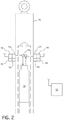
- the preferred embodiment of this invention is illustrated in Figure 2 .
- the invention employs vacuum micro-electronic device pulse sonar transceivers 34 and 44 (transmitter/receiver), which are radiation hardened and temperature tolerant in order to perform rod position indication with significantly better accuracy than the current system.
- Vacuum micro-electronic devices such as commercially available SSVDs supplied by Innosys Inc., Emeryville, CA, are suitable for this purpose.
- a description of a vacuum micro-electronic device can be found in U.S. Patent No. 7,005,783 .
- the existing magnetic coils 12 are replaced by a primary and redundant ceramic-based miniature antenna 36 with a very narrow beam width of approximately two degrees Beam Spread, which are located and supported in the interior of each control rod drive rod housing 26.
- Each control rod drive rod housing 26 is equipped with a primary and redundant set of hardware, which wirelessly transmit the control rod position data with a unique frequency in order to avoid interference.
- the primary hardware is shown to the right of Figure 2 and includes the primary pulse vacuum micro-electronic device transceiver 34.
- the primary vacuum micro-electronic device data transmitter 38 and a thermoelectric generator 40 whose hot junction is coupled to the control rod drive rod housing 26 by a heat pipe 42.
- the redundant hardware shown to the left of Figure 2 includes the redundant pulse vacuum micro-electronic device transceiver 44, the redundant vacuum micro-electronic device data transmitter 46 and the thermoelectric generator 48 whose hot junction is coupled to the drive rod housing 26 through a heat pipe 50.
- an electromagnetic interference site survey is performed in order to identify potential sources of noise or interference.
- the transmission frequency for the wireless data transfer is chosen such that the transmission frequency occupies an unused frequency band at the rod housing location.
- the received measured signal is also filtered as needed in order to minimize electrical interference and other related issues impacting the accuracy of the transmitted signal.
- the DC power required by the pulse sonar transceivers 34 and 44 and the wireless data transmitters 38 and 46 is generated by way of one or more of the thermoelectric generators 40 and 48 that have the hot junction connected to the drive rod travel housing 26 through heat pipes 42 and 50 and a cold junction of the thermoelectric device located on the opposite side of the thermoelectric generators. It should be noted that the transceivers 34 and 44 and the wireless data transmitters 38 and 46 can be powered by conventional existing cables if necessary. The data can also be transmitted through conventional field cables if necessary.
- FIG. 3 depicts a schematic of the system of this invention.
- This system employs a time of flight, phase difference and amplitude change methodology in order to determine the precise control rod position.
- Time of flight compilations are accomplished by measuring the time it takes for the signal to travel from the pulse transmitters 34 and 44 back to its source.
- the system as illustrated in Figure 3 , comprises a pulse repetition frequency oscillator 54 which together with the pulse transmitter 56 makes up the pulse generator that transmits the pulses at predetermined and known times, which allow the echoes 60 reflected from the top of the control rod 32 to return to the antenna 36 and be transmitted to the base station 52 for signal processing.
- the pulse transmitter 56 sends the signal 58 into the drive rod travel housing 26, the same signal is coupled and converted to a DC signal through a rectifying diode 68 and compared in the comparator 64 to a referenced voltage 62.
- the comparator output goes high when the transmitted signal is present, which energizes the relay coil K1, which opens the normally closed contact K1A and closes the normally open contact K1B.
- K1A is open; therefore, its only path is through K1B into the amplifier 66 and the wireless data transmitter 38.
- the phase and amplitude of the original signal are also known to the system by continuously splitting the pulse transmitter output and providing the frequency spectrum information to the wireless data transmitter.
- the wireless data transmitter sends the original raw signal (containing amplitude and phase) as well as the return signal once it bounces off the control rod, to a signal processing base station 52 for further computation.
- a series of thermocouples 70 are spaced along the control rod drive rod travel housing 26 as part of the system in order to adjust the speed of sound based upon the temperature.
- the system will include multiple thermocouples submerged in the coolant within the control rod drive rod travel housing at different elevations along the axial dimension of the housing 26. As the rod moves, abrupt coolant temperature changes will be known by the system through these thermocouples and transmitted to the base station 52 to correct the signal for the temperature changes.
- Typical pressurized water reactors operate at 15.3 megapascal (2,220 psig) and 330° Celsius (626 degrees Fahrenheit).
- this system provides improved accuracy, which would be mainly limited by the control rod drive mechanism step accuracy; with the conservatism built into the current safety margin essentially eliminated by the better accuracy.
- the accuracy of the current prior art system is +/- 7,94 cm (+/- 3.125 ").
- the accuracy of the system of this invention is only limited by the smallest rod movement which is 1,59 cm (0.625 ").
- the improved safety margins provided by this invention ultimately means that the reactors employing this concept can generate more electricity than their counterparts employing conventional technology. Redundant sensors provide the same accuracy instead of a half accuracy as with the current design. Only initial installation calibration is needed and sensor interaction issues within the rod travel housing and with adjacent rod housings are eliminated.
- control rod position monitoring system of this invention provides substantially improved accuracy over current systems. Additionally, the drive rods no longer have to be ferromagnetic.
Landscapes
- Engineering & Computer Science (AREA)
- Physics & Mathematics (AREA)
- Radar, Positioning & Navigation (AREA)
- Remote Sensing (AREA)
- General Physics & Mathematics (AREA)
- Computer Networks & Wireless Communication (AREA)
- Acoustics & Sound (AREA)
- Plasma & Fusion (AREA)
- General Engineering & Computer Science (AREA)
- High Energy & Nuclear Physics (AREA)
- Chemical & Material Sciences (AREA)
- Chemical Kinetics & Catalysis (AREA)
- Monitoring And Testing Of Nuclear Reactors (AREA)
- Measurement Of Velocity Or Position Using Acoustic Or Ultrasonic Waves (AREA)
Claims (14)
- Kernreaktorsystem mit einem Reaktorbehälter (10), der einen nuklearen Kern (28), in welchem Spaltungsreaktionen innerhalb einer Druckhülle des Reaktorbehälters stattfinden, und ein Steuerstabsystem zur Steuerung der Spaltungsreaktionen einhaust, wobei das Steuerstabsystem umfasst:einen Steuerstab (30), der dazu ausgestaltet ist, sich innerhalb eines schallleitenden Kühlmittels in den und aus dem nuklearen Kern (28) heraus zu bewegen, um die Spaltungsreaktionen zu steuern;ein Antriebssystem (32) zum Antreiben des Steuerstabs (30) in den und aus dem Kern (28) heraus; undein System zur Überwachung der Steuerstabposition, umfassend:einen Sonarimpulsgenerator (34), der dazu ausgestaltet ist, eine Reihe von Sonarimpulsen zu erzeugen; eine Antenne (36), die fix innerhalb der Druckhülle über einer oberen Bewegungsgrenze des Steuerstabs (30) positioniert und dazu ausgestaltet ist, die Sonarimpulse, die durch den Sonarimpulsgenerator (34) erzeugt werden, zu empfangen, und die Sonarimpulse an den oberen Abschnitt des Steuerstabs zu übertragen, und ein von dem Steuerstab reflektiertes Sonarsignal zu empfangen und das reflektierte Sonarsignal an eine ausgewählte Stelle in einem Abstand von der Antenne außerhalb der Druckhülle zu kommunizieren;undeinen Empfänger (52), der in dem Abstand von der Antenne (36) positioniert und dazu ausgestaltet ist, das reflektierte Sonarsignal zu empfangen und das reflektierte Sonarsignal an eine Verarbeitungseinheit (20) zu kommunizieren, die dazu ausgestaltet ist, das reflektierte Sonarsignal zu analysieren, um eine Steuerstabposition zu bestimmen,wobei der Sonarimpulsgenerator (34) außerhalb des Kühlmittels getragen wird und die Reihe von Sonarimpulsen drahtlos an die Antenne (36) überträgt.
- Kernreaktorsystem nach Anspruch 1, wobei der Sonarimpulsgenerator (34) eine vakuum-mikroelektronische Vorrichtung ist.
- Kernreaktorsystem nach Anspruch 1, wobei der Sonarimpulsgenerator (34) und der Empfänger (34) einen vakuum-mikroelektronischen Sender/Empfänger bilden.
- Kernreaktorsystem nach Anspruch 1, wobei der Steuerstab (30) eine Vielzahl von separat beweglichen Steuerstäben umfasst, wobei jeder der separat beweglichen Steuerstäbe ein entsprechendes System zur Überwachung der Steuerstabposition aufweist, wobei die Sonarimpulse für jedes der Systeme zur Überwachung der Position der separat beweglichen Steuerstäbe seine eigene eindeutige Frequenz aufweist.
- Kernreaktorsystem nach Anspruch 4, wobei die jeweiligen Frequenzen der Sonarimpulse sich von allen anderen Frequenzen von elektromagnetischen Störgeräuschen innerhalb des Kernreaktorsystems unterscheiden.
- Kernreaktorsystem nach Anspruch 1, wobei das System zur Überwachung der Steuerstabposition redundante Systeme zur Überwachung der Steuerstabposition umfasst, die zwei unterschiedliche Sonarpulsgeneratoren (34) beinhalten, die voneinander unabhängig sind, sowie zwei unterschiedliche Empfänger (34), die voneinander unabhängig sind.
- Kernreaktorsystem nach Anspruch 6, umfassend zwei unterschiedliche und separate Antennen (36).
- Kernreaktorsystem nach Anspruch 6, wobei die Sonarimpulse, die von den zwei unterschiedlichen Sonarimpulsgeneratoren (34) emittiert werden, auf separaten, unterschiedlichen Frequenzen emittiert werden.
- Kernreaktorsystem nach Anspruch 1, wobei der Steuerstab (30) eine Steuerstab-Antriebsstange (32) umfasst, und ein Steuerstab-Antriebsstangengehäuse (26) einen oberen Abschnitt des Bewegungswegs der Steuerstab-Antriebsstange umgibt, wobei die Antenne (36) innerhalb eines Innenraums des Steuerstab-Antriebsstangengehäuses getragen wird.
- Kernreaktorsystem nach Anspruch 9, wobei Leistung, die erforderlich ist, um den Sonarimpulsgenerator und den Empfänger (34) mit Energie zu versorgen, von einem thermoelektrischen Generator (40, 48) geliefert wird, mit einem heißen Anschluss, der an dem Steuerstab-Antriebsstangengehäuse (26) angebracht ist, und einem kalten Anschluss, der sich dem heißen Anschluss gegenüber von dem Steuerstab-Antriebsstangengehäuse entfernt befindet.
- Kernreaktorsystem nach Anspruch 9, umfassend einen Datenübertrager (38), der einen ursprünglichen Sonarimpuls aus der Reihe von Sonarimpulsen und ein entsprechendes der reflektierten Sonarsignale empfängt, die jeweils die Amplitude und Phase beinhalten, und den ursprünglichen Sonarimpuls und das reflektierte Sonarsignal zur Berechnung an eine Signalverarbeitungs-Basisstation (52) sendet.
- Kernreaktorsystem nach Anspruch 11, der einen Temperatursensor (70) zur Überwachung einer Temperatur innerhalb des Steuerstab-Antriebsstangen-Bewegungsgehäuses (26) beinhaltet und dazu betätigbar ist, um diese Temperatur an den Datenübertrager (38) zu kommunizieren, der betätigbar ist, um die Temperatur an die Signalverarbeitungs-Basisstation (52) zu übertragen.
- Kernreaktorsystem nach Anspruch 12, wobei der Temperatursensor (70) eine Vielzahl von Temperatursensoren beinhaltet, die entlang des Steuerstab-Antriebsstangengehäuses (26) beabstandet sind.
- Kernreaktorsystem nach Anspruch 12, wobei die Signalverarbeitungs-Basisstation (52) dazu ausgestaltet ist, die Laufzeit des ursprünglichen Sonarimpulses (58) und des reflektierten Sonarsignals (60) zu bestimmen und die Bestimmung mit der Temperatur (70) zu kompensieren.
Applications Claiming Priority (2)
| Application Number | Priority Date | Filing Date | Title |
|---|---|---|---|
| US14/996,439 US10020081B2 (en) | 2016-01-15 | 2016-01-15 | Nuclear control rod position indication system |
| PCT/US2017/012782 WO2017123510A1 (en) | 2016-01-15 | 2017-01-10 | Nuclear control rod position indication system |
Publications (3)
| Publication Number | Publication Date |
|---|---|
| EP3405960A1 EP3405960A1 (de) | 2018-11-28 |
| EP3405960A4 EP3405960A4 (de) | 2019-08-07 |
| EP3405960B1 true EP3405960B1 (de) | 2020-08-19 |
Family
ID=59311641
Family Applications (1)
| Application Number | Title | Priority Date | Filing Date |
|---|---|---|---|
| EP17738779.2A Active EP3405960B1 (de) | 2016-01-15 | 2017-01-10 | Positionsanzeigesystem für kernregelstab |
Country Status (7)
| Country | Link |
|---|---|
| US (1) | US10020081B2 (de) |
| EP (1) | EP3405960B1 (de) |
| JP (1) | JP7018883B2 (de) |
| KR (1) | KR102639015B1 (de) |
| CN (1) | CN108475547B (de) |
| ES (1) | ES2823126T3 (de) |
| WO (1) | WO2017123510A1 (de) |
Families Citing this family (10)
| Publication number | Priority date | Publication date | Assignee | Title |
|---|---|---|---|---|
| US11355252B2 (en) * | 2016-12-30 | 2022-06-07 | Nuscale Power, Llc | Control rod drive mechanism with heat pipe cooling |
| US10910115B2 (en) * | 2017-03-08 | 2021-02-02 | Ge-Hitachi Nuclear Energy Americas Llc | Digital systems and methods for high precision control in nuclear reactors |
| CN107833643B (zh) * | 2017-10-16 | 2019-05-24 | 中核核电运行管理有限公司 | 全数字化棒位测量装置及其方法 |
| KR102633738B1 (ko) | 2017-12-08 | 2024-02-06 | 웨스팅하우스 일렉트릭 컴퍼니 엘엘씨 | 핵 반응로에서 사용 가능한 검출 장치, 및 연관된 방법 |
| EP3966836A2 (de) | 2019-05-10 | 2022-03-16 | Westinghouse Electric Company Llc | System und verfahren zur digitalen stangenpositionsanzeige |
| US11127507B2 (en) * | 2019-09-09 | 2021-09-21 | Westinghouse Electric Company Llc | Fuel rod sensor system with inductive coupling |
| CN110828003B (zh) * | 2019-11-15 | 2022-03-11 | 中国原子能科学研究院 | 信号处理系统 |
| FR3109010B1 (fr) * | 2020-04-02 | 2022-04-08 | Soc Technique Pour Lenergie Atomique | Ensemble de contrôle de la désolidarisation entre une grappe de contrôle et une tige de commande d'un dispositif de contrôle de la réactivité d'une réacteur nucléaire |
| US11862350B2 (en) | 2021-01-22 | 2024-01-02 | Westinghouse Electric Company Llc | Nuclear movable element position indication apparatus, system, and method |
| KR102682866B1 (ko) | 2024-04-24 | 2024-07-09 | 주식회사 루스프로덕트 | 향상된 충격 흡수력을 제공하는 경량 가방 |
Family Cites Families (23)
| Publication number | Priority date | Publication date | Assignee | Title |
|---|---|---|---|---|
| DE2122190A1 (de) * | 1971-05-05 | 1972-11-23 | Licentia Patent-Verwaltungs-Gmbh, 6000 Frankfurt | Anordnung zur Anzeige der Stellung von Kernreaktorsteuerstäben |
| US4008455A (en) * | 1975-02-24 | 1977-02-15 | Westinghouse Electric Corporation | Method of making self-calibrated displacement measurements |
| JPS54140095A (en) * | 1978-04-24 | 1979-10-30 | Toshiba Corp | Control rod position detector |
| JPS5670494A (en) * | 1979-11-14 | 1981-06-12 | Tokyo Shibaura Electric Co | Control rod drive mechanism |
| FR2499294A1 (fr) * | 1981-02-04 | 1982-08-06 | Framatome Sa | Procede et dispositif de surveillance des barres de controles d'un reacteur nucleaire |
| FR2542910B1 (fr) * | 1983-03-18 | 1985-07-19 | Framatome Sa | Dispositif de reperage de position des barres de controle d'un reacteur nucleaire |
| DE3810503A1 (de) * | 1988-03-28 | 1989-10-19 | Siemens Ag | Kernreaktor mit einem in den reaktorkern einfahrbaren steuerstab |
| CN1012770B (zh) * | 1990-02-15 | 1991-06-05 | 清华大学 | 反应堆控制棒超声波棒位测量系统 |
| US5229066A (en) | 1991-08-05 | 1993-07-20 | Westinghouse Electric Corp. | Control rod position indication system |
| US5276719A (en) | 1991-08-14 | 1994-01-04 | Siemens Aktiengesellschaft | Hydraulic control rod drive for a nuclear reactor |
| JP2728834B2 (ja) | 1992-09-29 | 1998-03-18 | 株式会社東芝 | 制御棒位置検出装置 |
| US5568528A (en) * | 1994-11-21 | 1996-10-22 | Westinghouse Electric Corporation | Method and system for compensating a rod position indication system for non-linearity |
| JPH08170997A (ja) * | 1994-12-19 | 1996-07-02 | Ishikawajima Harima Heavy Ind Co Ltd | 原子炉圧力容器の自動探傷検査装置 |
| JPH08240692A (ja) * | 1995-03-06 | 1996-09-17 | Kansai Electric Power Co Inc:The | 原子炉の制御棒位置検出装置 |
| US5841824A (en) * | 1997-05-13 | 1998-11-24 | Westinghouse Electric Corporation | System and method for testing the free fall time of nuclear reactor control rods |
| JP2000028781A (ja) | 1998-07-09 | 2000-01-28 | Mitsubishi Electric Corp | 制御棒挿入状態監視装置 |
| US7005783B2 (en) | 2002-02-04 | 2006-02-28 | Innosys, Inc. | Solid state vacuum devices and method for making the same |
| US20040091076A1 (en) | 2002-11-08 | 2004-05-13 | Pacific Gas & Electric Company | Method and system for nondestructive inspection of components |
| US7679996B2 (en) * | 2005-06-13 | 2010-03-16 | Robert Ray Gross | Methods and device for ultrasonic range sensing |
| US8903033B2 (en) | 2008-01-09 | 2014-12-02 | Analysis and Measurement Service Corporation | High resolution digital rod position indication system for nuclear power plants |
| US10032529B2 (en) * | 2010-12-09 | 2018-07-24 | Westinghouse Electric Company Llc | Nuclear reactor internal electric control rod drive mechanism assembly |
| US9620255B2 (en) * | 2010-12-20 | 2017-04-11 | Westinghouse Electric Company Llc | Nuclear control rod position indication system |
| US8767903B2 (en) * | 2011-01-07 | 2014-07-01 | Westinghouse Electric Company Llc | Wireless in-core neutron monitor |
-
2016
- 2016-01-15 US US14/996,439 patent/US10020081B2/en active Active
-
2017
- 2017-01-10 ES ES17738779T patent/ES2823126T3/es active Active
- 2017-01-10 WO PCT/US2017/012782 patent/WO2017123510A1/en not_active Ceased
- 2017-01-10 EP EP17738779.2A patent/EP3405960B1/de active Active
- 2017-01-10 KR KR1020187023358A patent/KR102639015B1/ko active Active
- 2017-01-10 CN CN201780006611.9A patent/CN108475547B/zh active Active
- 2017-01-10 JP JP2018532368A patent/JP7018883B2/ja active Active
Non-Patent Citations (1)
| Title |
|---|
| None * |
Also Published As
| Publication number | Publication date |
|---|---|
| JP7018883B2 (ja) | 2022-02-14 |
| KR20180095114A (ko) | 2018-08-24 |
| US10020081B2 (en) | 2018-07-10 |
| EP3405960A1 (de) | 2018-11-28 |
| WO2017123510A1 (en) | 2017-07-20 |
| CN108475547A (zh) | 2018-08-31 |
| US20170206990A1 (en) | 2017-07-20 |
| JP2019505778A (ja) | 2019-02-28 |
| KR102639015B1 (ko) | 2024-02-20 |
| CN108475547B (zh) | 2022-09-16 |
| ES2823126T3 (es) | 2021-05-06 |
| EP3405960A4 (de) | 2019-08-07 |
Similar Documents
| Publication | Publication Date | Title |
|---|---|---|
| EP3405960B1 (de) | Positionsanzeigesystem für kernregelstab | |
| EP2661644B1 (de) | Selbstangetriebener drahtloser in-core-detektor | |
| KR101694580B1 (ko) | 무선 노내 중성자 모니터 | |
| CN108713229B (zh) | 利用超声光谱系统的实时反应堆冷却系统硼浓度监测器 | |
| US5841824A (en) | System and method for testing the free fall time of nuclear reactor control rods | |
| US11728057B2 (en) | Nuclear fuel failure protection system | |
| JP7022692B2 (ja) | 原子炉冷却系配管温度分布測定システム | |
| EP0483294B1 (de) | Verfahren zum ununterbrochenen leistungsbetrieb eines kernreaktors mit regelstaeben deren position von einer sollstellung abweicht | |
| US9250277B1 (en) | Magnetically coupled, high resolution linear position sensor for use in high temperature, high pressure environment | |
| US20130077727A1 (en) | Rod position detection apparatus and method | |
| Hans et al. | Flow measurement in main sodium pipes | |
| EP2957932B1 (de) | Verfahren zur optimierung der ausgabesignals eines sensors | |
| KR101959093B1 (ko) | 자기 출력식 무선 노내 검출기 | |
| Druzhinin et al. | Intelligent measuring diagnostic transducers of displacement for the control and safety systems of nuclear reactors | |
| Procter et al. | Neutron Flux Measurements for the PBMR DPP | |
| Imbert | The Saint-Chamond-Granat Precision Tide-Guage | |
| JPH039298A (ja) | 中性子束測定装置 | |
| JPH07151894A (ja) | 原子炉出力計測装置およびその計測方法 | |
| Billeter | Displacement Measurement Sensor for Use in Loss-of-Fluid-Test Reactor | |
| McGough | Monthly Report No. 7, March 1976, of US Representative to Interatom, Bensberg, Germany |
Legal Events
| Date | Code | Title | Description |
|---|---|---|---|
| STAA | Information on the status of an ep patent application or granted ep patent |
Free format text: STATUS: THE INTERNATIONAL PUBLICATION HAS BEEN MADE |
|
| PUAI | Public reference made under article 153(3) epc to a published international application that has entered the european phase |
Free format text: ORIGINAL CODE: 0009012 |
|
| STAA | Information on the status of an ep patent application or granted ep patent |
Free format text: STATUS: REQUEST FOR EXAMINATION WAS MADE |
|
| 17P | Request for examination filed |
Effective date: 20180620 |
|
| AK | Designated contracting states |
Kind code of ref document: A1 Designated state(s): AL AT BE BG CH CY CZ DE DK EE ES FI FR GB GR HR HU IE IS IT LI LT LU LV MC MK MT NL NO PL PT RO RS SE SI SK SM TR |
|
| AX | Request for extension of the european patent |
Extension state: BA ME |
|
| DAV | Request for validation of the european patent (deleted) | ||
| DAX | Request for extension of the european patent (deleted) | ||
| REG | Reference to a national code |
Ref country code: DE Ref legal event code: R079 Ref document number: 602017021993 Country of ref document: DE Free format text: PREVIOUS MAIN CLASS: G21C0017120000 Ipc: G21C0007360000 |
|
| A4 | Supplementary search report drawn up and despatched |
Effective date: 20190710 |
|
| RIC1 | Information provided on ipc code assigned before grant |
Ipc: G21C 17/12 20060101ALI20190704BHEP Ipc: G21C 7/36 20060101AFI20190704BHEP Ipc: G01S 15/10 20060101ALI20190704BHEP Ipc: G01S 7/52 20060101ALI20190704BHEP Ipc: G01S 15/88 20060101ALI20190704BHEP |
|
| STAA | Information on the status of an ep patent application or granted ep patent |
Free format text: STATUS: EXAMINATION IS IN PROGRESS |
|
| 17Q | First examination report despatched |
Effective date: 20200317 |
|
| GRAP | Despatch of communication of intention to grant a patent |
Free format text: ORIGINAL CODE: EPIDOSNIGR1 |
|
| STAA | Information on the status of an ep patent application or granted ep patent |
Free format text: STATUS: GRANT OF PATENT IS INTENDED |
|
| INTG | Intention to grant announced |
Effective date: 20200610 |
|
| GRAS | Grant fee paid |
Free format text: ORIGINAL CODE: EPIDOSNIGR3 |
|
| GRAA | (expected) grant |
Free format text: ORIGINAL CODE: 0009210 |
|
| STAA | Information on the status of an ep patent application or granted ep patent |
Free format text: STATUS: THE PATENT HAS BEEN GRANTED |
|
| AK | Designated contracting states |
Kind code of ref document: B1 Designated state(s): AL AT BE BG CH CY CZ DE DK EE ES FI FR GB GR HR HU IE IS IT LI LT LU LV MC MK MT NL NO PL PT RO RS SE SI SK SM TR |
|
| REG | Reference to a national code |
Ref country code: CH Ref legal event code: EP |
|
| REG | Reference to a national code |
Ref country code: DE Ref legal event code: R096 Ref document number: 602017021993 Country of ref document: DE |
|
| REG | Reference to a national code |
Ref country code: AT Ref legal event code: REF Ref document number: 1304867 Country of ref document: AT Kind code of ref document: T Effective date: 20200915 |
|
| REG | Reference to a national code |
Ref country code: IE Ref legal event code: FG4D |
|
| REG | Reference to a national code |
Ref country code: SE Ref legal event code: TRGR |
|
| REG | Reference to a national code |
Ref country code: LT Ref legal event code: MG4D |
|
| REG | Reference to a national code |
Ref country code: NL Ref legal event code: MP Effective date: 20200819 |
|
| PG25 | Lapsed in a contracting state [announced via postgrant information from national office to epo] |
Ref country code: LT Free format text: LAPSE BECAUSE OF FAILURE TO SUBMIT A TRANSLATION OF THE DESCRIPTION OR TO PAY THE FEE WITHIN THE PRESCRIBED TIME-LIMIT Effective date: 20200819 Ref country code: BG Free format text: LAPSE BECAUSE OF FAILURE TO SUBMIT A TRANSLATION OF THE DESCRIPTION OR TO PAY THE FEE WITHIN THE PRESCRIBED TIME-LIMIT Effective date: 20201119 Ref country code: PT Free format text: LAPSE BECAUSE OF FAILURE TO SUBMIT A TRANSLATION OF THE DESCRIPTION OR TO PAY THE FEE WITHIN THE PRESCRIBED TIME-LIMIT Effective date: 20201221 Ref country code: NO Free format text: LAPSE BECAUSE OF FAILURE TO SUBMIT A TRANSLATION OF THE DESCRIPTION OR TO PAY THE FEE WITHIN THE PRESCRIBED TIME-LIMIT Effective date: 20201119 Ref country code: FI Free format text: LAPSE BECAUSE OF FAILURE TO SUBMIT A TRANSLATION OF THE DESCRIPTION OR TO PAY THE FEE WITHIN THE PRESCRIBED TIME-LIMIT Effective date: 20200819 Ref country code: HR Free format text: LAPSE BECAUSE OF FAILURE TO SUBMIT A TRANSLATION OF THE DESCRIPTION OR TO PAY THE FEE WITHIN THE PRESCRIBED TIME-LIMIT Effective date: 20200819 Ref country code: GR Free format text: LAPSE BECAUSE OF FAILURE TO SUBMIT A TRANSLATION OF THE DESCRIPTION OR TO PAY THE FEE WITHIN THE PRESCRIBED TIME-LIMIT Effective date: 20201120 |
|
| REG | Reference to a national code |
Ref country code: AT Ref legal event code: MK05 Ref document number: 1304867 Country of ref document: AT Kind code of ref document: T Effective date: 20200819 |
|
| PG25 | Lapsed in a contracting state [announced via postgrant information from national office to epo] |
Ref country code: IS Free format text: LAPSE BECAUSE OF FAILURE TO SUBMIT A TRANSLATION OF THE DESCRIPTION OR TO PAY THE FEE WITHIN THE PRESCRIBED TIME-LIMIT Effective date: 20201219 Ref country code: LV Free format text: LAPSE BECAUSE OF FAILURE TO SUBMIT A TRANSLATION OF THE DESCRIPTION OR TO PAY THE FEE WITHIN THE PRESCRIBED TIME-LIMIT Effective date: 20200819 Ref country code: NL Free format text: LAPSE BECAUSE OF FAILURE TO SUBMIT A TRANSLATION OF THE DESCRIPTION OR TO PAY THE FEE WITHIN THE PRESCRIBED TIME-LIMIT Effective date: 20200819 Ref country code: RS Free format text: LAPSE BECAUSE OF FAILURE TO SUBMIT A TRANSLATION OF THE DESCRIPTION OR TO PAY THE FEE WITHIN THE PRESCRIBED TIME-LIMIT Effective date: 20200819 Ref country code: PL Free format text: LAPSE BECAUSE OF FAILURE TO SUBMIT A TRANSLATION OF THE DESCRIPTION OR TO PAY THE FEE WITHIN THE PRESCRIBED TIME-LIMIT Effective date: 20200819 |
|
| PG25 | Lapsed in a contracting state [announced via postgrant information from national office to epo] |
Ref country code: CZ Free format text: LAPSE BECAUSE OF FAILURE TO SUBMIT A TRANSLATION OF THE DESCRIPTION OR TO PAY THE FEE WITHIN THE PRESCRIBED TIME-LIMIT Effective date: 20200819 Ref country code: DK Free format text: LAPSE BECAUSE OF FAILURE TO SUBMIT A TRANSLATION OF THE DESCRIPTION OR TO PAY THE FEE WITHIN THE PRESCRIBED TIME-LIMIT Effective date: 20200819 Ref country code: RO Free format text: LAPSE BECAUSE OF FAILURE TO SUBMIT A TRANSLATION OF THE DESCRIPTION OR TO PAY THE FEE WITHIN THE PRESCRIBED TIME-LIMIT Effective date: 20200819 Ref country code: SM Free format text: LAPSE BECAUSE OF FAILURE TO SUBMIT A TRANSLATION OF THE DESCRIPTION OR TO PAY THE FEE WITHIN THE PRESCRIBED TIME-LIMIT Effective date: 20200819 Ref country code: EE Free format text: LAPSE BECAUSE OF FAILURE TO SUBMIT A TRANSLATION OF THE DESCRIPTION OR TO PAY THE FEE WITHIN THE PRESCRIBED TIME-LIMIT Effective date: 20200819 |
|
| REG | Reference to a national code |
Ref country code: ES Ref legal event code: FG2A Ref document number: 2823126 Country of ref document: ES Kind code of ref document: T3 Effective date: 20210506 |
|
| REG | Reference to a national code |
Ref country code: DE Ref legal event code: R097 Ref document number: 602017021993 Country of ref document: DE |
|
| PG25 | Lapsed in a contracting state [announced via postgrant information from national office to epo] |
Ref country code: AL Free format text: LAPSE BECAUSE OF FAILURE TO SUBMIT A TRANSLATION OF THE DESCRIPTION OR TO PAY THE FEE WITHIN THE PRESCRIBED TIME-LIMIT Effective date: 20200819 Ref country code: AT Free format text: LAPSE BECAUSE OF FAILURE TO SUBMIT A TRANSLATION OF THE DESCRIPTION OR TO PAY THE FEE WITHIN THE PRESCRIBED TIME-LIMIT Effective date: 20200819 |
|
| PLBE | No opposition filed within time limit |
Free format text: ORIGINAL CODE: 0009261 |
|
| STAA | Information on the status of an ep patent application or granted ep patent |
Free format text: STATUS: NO OPPOSITION FILED WITHIN TIME LIMIT |
|
| PG25 | Lapsed in a contracting state [announced via postgrant information from national office to epo] |
Ref country code: SK Free format text: LAPSE BECAUSE OF FAILURE TO SUBMIT A TRANSLATION OF THE DESCRIPTION OR TO PAY THE FEE WITHIN THE PRESCRIBED TIME-LIMIT Effective date: 20200819 |
|
| 26N | No opposition filed |
Effective date: 20210520 |
|
| PG25 | Lapsed in a contracting state [announced via postgrant information from national office to epo] |
Ref country code: IT Free format text: LAPSE BECAUSE OF FAILURE TO SUBMIT A TRANSLATION OF THE DESCRIPTION OR TO PAY THE FEE WITHIN THE PRESCRIBED TIME-LIMIT Effective date: 20200819 |
|
| PG25 | Lapsed in a contracting state [announced via postgrant information from national office to epo] |
Ref country code: SI Free format text: LAPSE BECAUSE OF FAILURE TO SUBMIT A TRANSLATION OF THE DESCRIPTION OR TO PAY THE FEE WITHIN THE PRESCRIBED TIME-LIMIT Effective date: 20200819 Ref country code: MC Free format text: LAPSE BECAUSE OF FAILURE TO SUBMIT A TRANSLATION OF THE DESCRIPTION OR TO PAY THE FEE WITHIN THE PRESCRIBED TIME-LIMIT Effective date: 20200819 |
|
| REG | Reference to a national code |
Ref country code: CH Ref legal event code: PL |
|
| PG25 | Lapsed in a contracting state [announced via postgrant information from national office to epo] |
Ref country code: LU Free format text: LAPSE BECAUSE OF NON-PAYMENT OF DUE FEES Effective date: 20210110 |
|
| REG | Reference to a national code |
Ref country code: BE Ref legal event code: MM Effective date: 20210131 |
|
| PG25 | Lapsed in a contracting state [announced via postgrant information from national office to epo] |
Ref country code: LI Free format text: LAPSE BECAUSE OF NON-PAYMENT OF DUE FEES Effective date: 20210131 Ref country code: CH Free format text: LAPSE BECAUSE OF NON-PAYMENT OF DUE FEES Effective date: 20210131 |
|
| PG25 | Lapsed in a contracting state [announced via postgrant information from national office to epo] |
Ref country code: IE Free format text: LAPSE BECAUSE OF NON-PAYMENT OF DUE FEES Effective date: 20210110 |
|
| PG25 | Lapsed in a contracting state [announced via postgrant information from national office to epo] |
Ref country code: BE Free format text: LAPSE BECAUSE OF NON-PAYMENT OF DUE FEES Effective date: 20210131 |
|
| REG | Reference to a national code |
Ref country code: DE Ref legal event code: R082 Ref document number: 602017021993 Country of ref document: DE Representative=s name: FLEUCHAUS & GALLO PARTNERSCHAFT MBB - PATENT- , DE Ref country code: DE Ref legal event code: R082 Ref document number: 602017021993 Country of ref document: DE Representative=s name: FLEUCHAUS & GALLO PARTNERSCHAFT MBB PATENTANWA, DE |
|
| PG25 | Lapsed in a contracting state [announced via postgrant information from national office to epo] |
Ref country code: CY Free format text: LAPSE BECAUSE OF FAILURE TO SUBMIT A TRANSLATION OF THE DESCRIPTION OR TO PAY THE FEE WITHIN THE PRESCRIBED TIME-LIMIT Effective date: 20200819 |
|
| PG25 | Lapsed in a contracting state [announced via postgrant information from national office to epo] |
Ref country code: HU Free format text: LAPSE BECAUSE OF FAILURE TO SUBMIT A TRANSLATION OF THE DESCRIPTION OR TO PAY THE FEE WITHIN THE PRESCRIBED TIME-LIMIT; INVALID AB INITIO Effective date: 20170110 |
|
| PG25 | Lapsed in a contracting state [announced via postgrant information from national office to epo] |
Ref country code: MK Free format text: LAPSE BECAUSE OF FAILURE TO SUBMIT A TRANSLATION OF THE DESCRIPTION OR TO PAY THE FEE WITHIN THE PRESCRIBED TIME-LIMIT Effective date: 20200819 |
|
| PG25 | Lapsed in a contracting state [announced via postgrant information from national office to epo] |
Ref country code: TR Free format text: LAPSE BECAUSE OF FAILURE TO SUBMIT A TRANSLATION OF THE DESCRIPTION OR TO PAY THE FEE WITHIN THE PRESCRIBED TIME-LIMIT Effective date: 20200819 |
|
| PG25 | Lapsed in a contracting state [announced via postgrant information from national office to epo] |
Ref country code: MT Free format text: LAPSE BECAUSE OF FAILURE TO SUBMIT A TRANSLATION OF THE DESCRIPTION OR TO PAY THE FEE WITHIN THE PRESCRIBED TIME-LIMIT Effective date: 20200819 |
|
| PGFP | Annual fee paid to national office [announced via postgrant information from national office to epo] |
Ref country code: DE Payment date: 20250127 Year of fee payment: 9 |
|
| PGFP | Annual fee paid to national office [announced via postgrant information from national office to epo] |
Ref country code: ES Payment date: 20250217 Year of fee payment: 9 |
|
| PGFP | Annual fee paid to national office [announced via postgrant information from national office to epo] |
Ref country code: SE Payment date: 20250128 Year of fee payment: 9 |
|
| PGFP | Annual fee paid to national office [announced via postgrant information from national office to epo] |
Ref country code: FR Payment date: 20250131 Year of fee payment: 9 |
|
| PGFP | Annual fee paid to national office [announced via postgrant information from national office to epo] |
Ref country code: GB Payment date: 20250130 Year of fee payment: 9 |