EP3405936B1 - Gasdetektor zur detektion von mehreren gasen - Google Patents
Gasdetektor zur detektion von mehreren gasen Download PDFInfo
- Publication number
- EP3405936B1 EP3405936B1 EP17708960.4A EP17708960A EP3405936B1 EP 3405936 B1 EP3405936 B1 EP 3405936B1 EP 17708960 A EP17708960 A EP 17708960A EP 3405936 B1 EP3405936 B1 EP 3405936B1
- Authority
- EP
- European Patent Office
- Prior art keywords
- alarm
- gas detector
- display
- screens
- information
- Prior art date
- Legal status (The legal status is an assumption and is not a legal conclusion. Google has not performed a legal analysis and makes no representation as to the accuracy of the status listed.)
- Active
Links
- 239000007789 gas Substances 0.000 title claims description 109
- 238000000034 method Methods 0.000 claims description 26
- VNWKTOKETHGBQD-UHFFFAOYSA-N methane Chemical compound C VNWKTOKETHGBQD-UHFFFAOYSA-N 0.000 claims description 6
- RWSOTUBLDIXVET-UHFFFAOYSA-N Dihydrogen sulfide Chemical compound S RWSOTUBLDIXVET-UHFFFAOYSA-N 0.000 claims description 3
- QVGXLLKOCUKJST-UHFFFAOYSA-N atomic oxygen Chemical compound [O] QVGXLLKOCUKJST-UHFFFAOYSA-N 0.000 claims description 2
- 229910052760 oxygen Inorganic materials 0.000 claims description 2
- 239000001301 oxygen Substances 0.000 claims description 2
- 230000004044 response Effects 0.000 claims description 2
- RAHZWNYVWXNFOC-UHFFFAOYSA-N Sulphur dioxide Chemical compound O=S=O RAHZWNYVWXNFOC-UHFFFAOYSA-N 0.000 claims 4
- UGFAIRIUMAVXCW-UHFFFAOYSA-N Carbon monoxide Chemical compound [O+]#[C-] UGFAIRIUMAVXCW-UHFFFAOYSA-N 0.000 claims 2
- 229910002091 carbon monoxide Inorganic materials 0.000 claims 2
- 231100001261 hazardous Toxicity 0.000 description 4
- 230000008901 benefit Effects 0.000 description 3
- 238000001514 detection method Methods 0.000 description 3
- 230000008569 process Effects 0.000 description 3
- 230000008859 change Effects 0.000 description 2
- 238000004891 communication Methods 0.000 description 2
- 238000005516 engineering process Methods 0.000 description 2
- 229910000037 hydrogen sulfide Inorganic materials 0.000 description 2
- 238000012986 modification Methods 0.000 description 2
- 230000004048 modification Effects 0.000 description 2
- 239000000126 substance Substances 0.000 description 2
- 238000012360 testing method Methods 0.000 description 2
- 208000027418 Wounds and injury Diseases 0.000 description 1
- 230000004075 alteration Effects 0.000 description 1
- 230000009286 beneficial effect Effects 0.000 description 1
- 230000005540 biological transmission Effects 0.000 description 1
- 238000012512 characterization method Methods 0.000 description 1
- 230000006378 damage Effects 0.000 description 1
- 230000006870 function Effects 0.000 description 1
- 208000014674 injury Diseases 0.000 description 1
- 238000012806 monitoring device Methods 0.000 description 1
- 238000012544 monitoring process Methods 0.000 description 1
- 230000000737 periodic effect Effects 0.000 description 1
- 238000006467 substitution reaction Methods 0.000 description 1
- 239000002341 toxic gas Substances 0.000 description 1
- 230000000007 visual effect Effects 0.000 description 1
Images


Classifications
-
- G—PHYSICS
- G08—SIGNALLING
- G08B—SIGNALLING OR CALLING SYSTEMS; ORDER TELEGRAPHS; ALARM SYSTEMS
- G08B21/00—Alarms responsive to a single specified undesired or abnormal condition and not otherwise provided for
- G08B21/02—Alarms for ensuring the safety of persons
- G08B21/12—Alarms for ensuring the safety of persons responsive to undesired emission of substances, e.g. pollution alarms
-
- G—PHYSICS
- G01—MEASURING; TESTING
- G01N—INVESTIGATING OR ANALYSING MATERIALS BY DETERMINING THEIR CHEMICAL OR PHYSICAL PROPERTIES
- G01N33/00—Investigating or analysing materials by specific methods not covered by groups G01N1/00 - G01N31/00
- G01N33/0004—Gaseous mixtures, e.g. polluted air
- G01N33/0009—General constructional details of gas analysers, e.g. portable test equipment
- G01N33/0062—General constructional details of gas analysers, e.g. portable test equipment concerning the measuring method or the display, e.g. intermittent measurement or digital display
- G01N33/0063—General constructional details of gas analysers, e.g. portable test equipment concerning the measuring method or the display, e.g. intermittent measurement or digital display using a threshold to release an alarm or displaying means
- G01N33/0065—General constructional details of gas analysers, e.g. portable test equipment concerning the measuring method or the display, e.g. intermittent measurement or digital display using a threshold to release an alarm or displaying means using more than one threshold
-
- G—PHYSICS
- G08—SIGNALLING
- G08B—SIGNALLING OR CALLING SYSTEMS; ORDER TELEGRAPHS; ALARM SYSTEMS
- G08B17/00—Fire alarms; Alarms responsive to explosion
- G08B17/10—Actuation by presence of smoke or gases, e.g. automatic alarm devices for analysing flowing fluid materials by the use of optical means
- G08B17/117—Actuation by presence of smoke or gases, e.g. automatic alarm devices for analysing flowing fluid materials by the use of optical means by using a detection device for specific gases, e.g. combustion products, produced by the fire
-
- G—PHYSICS
- G08—SIGNALLING
- G08B—SIGNALLING OR CALLING SYSTEMS; ORDER TELEGRAPHS; ALARM SYSTEMS
- G08B25/00—Alarm systems in which the location of the alarm condition is signalled to a central station, e.g. fire or police telegraphic systems
- G08B25/008—Alarm setting and unsetting, i.e. arming or disarming of the security system
-
- G—PHYSICS
- G08—SIGNALLING
- G08B—SIGNALLING OR CALLING SYSTEMS; ORDER TELEGRAPHS; ALARM SYSTEMS
- G08B25/00—Alarm systems in which the location of the alarm condition is signalled to a central station, e.g. fire or police telegraphic systems
- G08B25/14—Central alarm receiver or annunciator arrangements
Definitions
- gas detectors In hazardous work environments, user may carry gas detectors with them as they work, to allow for detection of gas exposure.
- the gas detector may alert the user if an exposure limits are reached while the user is wearing the gas detector.
- Gas detectors may comprise interfaces for communicating with the user, such as displays, lights, buzzers, and input buttons. Gas detectors may be configured with settings for alarms, exposure limits, display settings, light and buzzer settings, etc.
- a wireless location-based gas detection system and method includes a gas detector for wirelessly detecting location information associated with a hazardous gas event.
- the gas detector includes one or more remote gas sensors that monitor for the occurrence of a gas event and wirelessly communicates information with respect to the location of the event in association with time information to a server or location manager.
- a wireless communication device in association with one or more location anchor points periodically and under event conditions, transmits the location information and the gas concentration level.
- a location engine calculates an estimated location of the gas detector based on information received from the wireless communication device and provides the location data to the location manager.
- GB2329542 discloses a security control system, comprising a system controller (2) arranged to receive video signals from a plurality of video sources, and to selectively output a subset of the received video signals for display on a display means, and a display controller (10, 12) arranged to receive the subset of video signals output by the system controller, and to process those signals to generate images for display on the display means.
- the display controller (10, 12) is then arranged to cause any images generated from video signals associated with alarm signals to be displayed in a predetermined area (M11) of the display means.
- US2015/212034 discloses a room monitoring device designed and intended to detect a bowel movement (BM) of a person occupying the room, such as a baby or infant or an adult with special needs or in a care facility.
- the device tests the air for particular substances such as, but not limited to, methane and hydrogen sulfide. The test is performed multiple times per minute to reduce the chances of a false-positive detection.
- the device detects a positive BM, it alerts a user via Wi-Fi message, SMS text message, visual alerts (e.g., flashing lights), and/or audio alerts.
- US2015/379848 discloses an alert module, an event module, a notification trigger module, and a notification alert module.
- the alert module may be configured to receive a plurality of different sensor modality alerts.
- the event module may be configured to determine events based on the plurality of different sensor modality alerts.
- the notification trigger module may be configured to determine whether to cause transmission of notification alerts based on the determined events.
- the invention provides a gas detector according to claim 1 and a method for controlling a display of a gas detector according to claim 9.
- a gas detector may comprise a plurality of sensors configured to detect a plurality of characteristics of the ambient environment; a user interface comprising a display; and a controller configured to receive sensed data from the plurality of sensors; display the received sensed data via the display of the user interface, wherein the display includes information for more than one of the plurality of sensors; and change the display to an alarm screen that includes only alarm information, when the gas detector is in an alarm mode.
- Embodiments of the disclosure include systems and methods for controlling the display of a gas detector device.
- the gas detector device may be configured to display alarms or alerts to a user based on the data received by sensors within the gas detector.
- the alarms or alerts may comprise information about the received data, including current reading, exceeded limits, type of alarm, etc.
- a supervisor may have the opportunity to limit the amount of information available to an employee during an alarm, such that the employee has the right information in the right moment. Limiting the information available on the display of a gas detector during an alarm may prevent delay or confusion before the user evacuates.
- the system may be called "Only Alert” as it allows only the alarm or alert information to be displayed. The use of this system may benefit both novice and expert users when the protocol for response to an alarm is to evacuate first.
- Typical gas detectors may show all gas sensor information at all times, including during a gas alarm situation. While limiting the information may not be beneficial for all users, such as supervisors who need to assess the alarm situation, most workers do not need access to all of the information in order to appropriately respond to an alarm situation.
- Only Alert may be a user controlled feature, via software on the gas detector.
- an Only Alert system may be implemented into existing gas detector devices by updating the software of the device. When the Only Alert system is enabled and a gas alarm situation occurs, the gas detector display will only show the alarm gas channel information, omitting the rest.
- a gas detector device (such as the gas detector 100 shown in FIG. 1 ) using Only Alert may comprise a plurality of sensors 150 (or channels) configured to provide information about a plurality of gases and/or conditions, for example, oxygen levels, combustibles, and/or toxic gases.
- the gas detector device 100 may comprise a user interface 101 comprising a display 102 configured to display information for at least two sensors or channels.
- the gas detector 100 may comprise other user interface elements, such as buttons 152, indicators 154, sound generators, etc.
- the gas detector 100 may be designed for continuous and/or periodic monitoring, and may be mobile to be carried by a user.
- exemplary gas detectors may be used in underground utilities vaults, boiler rooms, industrial plants, chemical plants, refineries, and other similar work environments.
- the gas detector may comprise a controller, which may be processor, microprocessor, or other similar device, where the controller may be included in any of the embodiments disclosed herein.
- the controller may be capable of sending and receiving signals, displays, and other data.
- the controller may be configured to process data, format data, among other functions.
- the controller may comprise a memory, where the memory may store an application that can execute all the steps described in the disclosed embodiments.
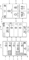
- FIGS. 2A-2C exemplary gas detector displays are shown, wherein the display may be part of a user interface 101 for the gas detector 100 (shown in FIG. 1 ).
- the gas detector may be in normal operating mode, and may not have any alarms or alerts.
- FIG. 2A shows a first example of a gas detector display 102, wherein the display 102 includes sections of information for a plurality of gases.
- the display includes a first section 111, second section 112, third section 113, fourth section 114, and fifth section 115, wherein each of the sections contains information about different sensor readings or data.
- the sections may contain gas identification as well as the current reading for that gas.
- the display 102 may comprise a general information section 140 comprising information such as battery life remaining, current time, access to other sections or displays, among other things.
- the general information section 140 may be located at the bottom of the display 102. In other embodiments, the general information section 140 may be located in another location within the display 102.
- FIG. 2B shows a second example of a gas detector display 104, wherein the display 104 includes sections of information for a plurality of gases.
- the display includes a first section 121, second section 122, third section 123, and fourth section 124, wherein each of the sections contains information about different sensor readings or data.
- the sections may contain gas identification as well as the current reading for that gas.
- the display 104 may comprise a general information section 140 comprising information such as battery life remaining, current time, access to other sections or displays, among other things.
- the general information section 140 may be located at the bottom of the display 104. In other embodiments, the general information section 140 may be located in another location within the display 104.
- FIG. 2C shows a third example of a gas detector display 106, wherein the display 106 includes sections of information for a plurality of gases.
- the display includes a first section 131, second section 132, third section 133, fourth section 134, and fifth section 135, wherein each of the sections contains information about different sensor readings or data.
- the sections may contain gas identification as well as the current reading for that gas.
- the display 106 may comprise a general information section 140 comprising information such as battery life remaining, current time, access to other sections or displays, among other things.
- the general information section 140 may be located at the bottom of the display 106. In other embodiments, the general information section 140 may be located in another position within the display 106.
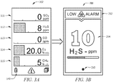
- the display 102 showing all of the plurality of gas readings may switch to an alarm screen 200 comprising only the alarm information.
- the alarm screen 200 may comprise an alarm identifier 212, a current reading 214, as well as other information about the alarm.
- the alarm screen 200 may comprise an indicator 210 for the number of alarm screens (explained in more detail below).
- the alarm screen 200 may be designed to provide only the critical information to a user, avoiding confusion or delay when the user is in a hazardous environment.
- the alarm screen 200 may comprise only the critical information associated with the alarm, and the user may be able to adequately respond to the alert or alarm without distraction.
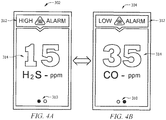
- FIGS. 4A-4B an embodiment is shown where there is more than one alarm detected by the gas detector.
- the normal operating display may switch to a full screen alarm display (or a first alarm screen 302).
- a second alarm screen 304 may be generated, where the first alarm screen 302 and second alarm screen 304 may be shown alternatively by the display of the gas detector.
- the alarm screens may comprise an alarm identifier 312, a current reading 314, as well as other information about the alarm.
- the alarm screens 302, 304 may comprise an indicator 310 for the number of alarm screens (two in this case). The indicator 310 may also highlight which screen is currently being shown on the display.
- the alarm screens 302, 304 may switch at predetermined time intervals.
- a user may press a button to switch between the two alarm screens 302 and 304.
- the normal operating display may switch to a full screen alarm display (or a first alarm screen 402). Then, if more than one alarm is issued, a second alarm screen 404 may be generated, and a third alarm screen 406 may be generated, where the first alarm screen 402, second alarm screen 404, and third alarm screen 406 may be shown alternatively by the display of the gas detector.
- the alarm screens may comprise an alarm identifier 412, a current reading 414, as well as other information about the alarm.
- the alarm screens may comprise an indicator 410 for the number of alarm screens (three in this case). The indicator 410 may also highlight which screen is currently being shown on the display.
- the alarm screens 402, 404, and 406 may switch at predetermined time intervals.
- a user may press a button to switch between the three alarm screens 402, 404, and 406.
- Some embodiments of the disclosure may comprise a gas detector configured to detect multiple gases, the gas detector comprising a plurality of sensors configured to detect a plurality of gases and conditions; a user interface comprising a display configured to display information received from the plurality of sensors; wherein when the gas detector is in normal operating mode, the display includes information for more than one of the plurality of sensors, and wherein when the gas detector is in an alarm or alert mode, the display changes to an alarm screen that includes only the alarm information.
- the alarm information comprises a single alarm or alert. In some embodiments, the alarm information comprises a plurality of alarms or alerts, and wherein the display is configured to switch between the alarm screens for each of the plurality of alarms. In some embodiments, the display automatically switches between the plurality of alarm screens at predefined time intervals. In some embodiments, the display switches between the plurality of alarm screens when a user presses a button. In some embodiments, the display is configured to indicate the number of alarm screens currently existing on the gas detector. In some embodiments, the alarm screen comprises a full screen display. In some embodiments, the alarm screen includes the type of alarm and current reading for that sensor. In some embodiments, the gas detector is configured to detect SO 2 , H 2 S, CO, O 2 , and CH 4 . In some embodiments, the display is further configured to switch back to the normal operating mode when the alarm mode is deactivated.
- Some embodiments of the disclosure include a method for controlling the display of a gas detector comprising receiving sensed data from a plurality of sensors of the gas detector; displaying the received sensed data on a user interface of the gas detector, wherein the user interface comprises a display, and wherein the display includes information for more than one of the plurality of sensors; and changing the display to an alarm screen that includes only the alarm information, when the gas detector is in an alarm or alert mode.
- the method may further comprise, when the alarm information comprises a plurality of alarms or alerts, switching between a plurality of alarm screens for each of the plurality of alarms. In some embodiments, switching between the plurality of alarm screens comprises automatically switching between the plurality of alarm screens at predefined time intervals. In some embodiments, switching between the plurality of alarm screens comprises switching between the plurality of alarm screens when a user presses a button. In some embodiments, the method may further comprise indicating, by the display, the number of alarm screens currently existing on the gas detector. In some embodiments, the alarm screen comprises a full screen display. In some embodiments, the alarm screen includes the type of alarm and current reading for that sensor. In some embodiments, the method may further comprise changing the display from the alarm screen to a normal operating screen, when the gas detector is no longer in alarm or alert mode, wherein the normal operating screen includes information for more than one of the plurality of sensors.
- a gas detector may comprise a plurality of sensors configured to detect a plurality of characteristics of the ambient environment; a user interface comprising a display; and a controller configured to receive sensed data from the plurality of sensors; display the received sensed data via the display of the user interface, wherein the display includes information for more than one of the plurality of sensors; and change the display to an alarm screen that includes only alarm information, when the gas detector is in an alarm mode.
- the alarm information comprises a plurality of alarms or alerts
- the display is configured to switch between a plurality of alarm screens for each of the plurality of alarms.
- the controller is further configured to automatically switch between the plurality of alarm screens at predefined time intervals.
- the controller is further configured to indicate the number of alarm screens currently existing on the gas detector.
- the controller is configured to switch back to a normal operating mode when the alarm mode is deactivated.
Landscapes
- Physics & Mathematics (AREA)
- General Physics & Mathematics (AREA)
- Engineering & Computer Science (AREA)
- Chemical & Material Sciences (AREA)
- Business, Economics & Management (AREA)
- Emergency Management (AREA)
- Health & Medical Sciences (AREA)
- General Health & Medical Sciences (AREA)
- Life Sciences & Earth Sciences (AREA)
- Analytical Chemistry (AREA)
- Combustion & Propulsion (AREA)
- Toxicology (AREA)
- Food Science & Technology (AREA)
- Medicinal Chemistry (AREA)
- Environmental & Geological Engineering (AREA)
- Biochemistry (AREA)
- Immunology (AREA)
- Pathology (AREA)
- Computer Security & Cryptography (AREA)
- Emergency Alarm Devices (AREA)
- Alarm Systems (AREA)
Claims (14)
- Gasdetektor (100), der konfiguriert ist, um mehrere Gase zu detektieren, wobei der Gasdetektor (100) umfasst:eine Vielzahl von Sensoren (150), die konfiguriert sind, um einer Vielzahl von Gasen und Bedingungen zu detektieren; undeine Benutzerschnittstelle (101), die eine Anzeige (102) umfasst, die konfiguriert ist, um Informationen anzuzeigen, die von der Vielzahl von Sensoren (150) empfangen werden,wobei:wenn sich der Gasdetektor (100) im Normalbetriebsmodus befindet, die Anzeige (102) Informationen über mehr als einen der Vielzahl von Sensoren (150) einschließt; undwenn sich der Gasdetektor (100) in einem Alarm- oder Warnmodus befindet, die Anzeige (102) zu einem Alarmbildschirm wechselt, der nur die Alarminformationen einschließt, wobei der Alarmbildschirm die Art des Alarms und den aktuellen Messwert dieses Sensors einschließt.
- Gasdetektor (100) nach Anspruch 1, wobei die Alarminformationen einen einzelnen Alarm oder eine einzelne Warnung umfassen.
- Gasdetektor (100) nach Anspruch 1, wobei die Alarminformationen eine Vielzahl von Alarmen oder Warnungen umfassen und wobei die Anzeige (102) konfiguriert ist, um zwischen den Alarmbildschirmen für jeden der Vielzahl von Alarmen umzuschalten.
- Gasdetektor (100) nach Anspruch 3, wobei die Anzeige (102) konfiguriert ist, um automatisch in vordefinierten Zeitintervallen zwischen der Vielzahl von Alarmbildschirmen umzuschalten.
- Gasdetektor (100) nach Anspruch 3, wobei die Anzeige (102) konfiguriert ist, um als Reaktion auf einen Benutzer, der eine Taste drückt, zwischen der Vielzahl von Alarmbildschirmen umzuschalten.
- Gasdetektor (100) nach Anspruch 3, wobei die Anzeige (102) konfiguriert ist, um die Anzahl von Alarmbildschirmen anzuzeigen, die gegenwärtig auf dem Gasdetektor (100) vorhanden sind.
- Gasdetektor (100) nach Anspruch 1, wobei der Gasdetektor (100) konfiguriert ist, um eines oder mehrere der Folgenden zu detektieren: Schwefeldioxid (SO2), Schwefelwasserstoff (H2S), Kohlenmonoxid (CO), Sauerstoff (O2) und Methan (CH4).
- Gasdetektor (100) nach Anspruch 1, wobei die Anzeige (102) konfiguriert ist, um in den Normalbetriebsmodus zurückzuschalten, wenn der Alarmmodus deaktiviert wird.
- Verfahren zum Steuern einer Anzeige (102) eines Gasdetektors (100), der konfiguriert ist, um mehrere Gase zu detektieren, umfassend:Empfangen von erfassten Daten von einer Vielzahl von Sensoren (150) des Gasdetektors (100);Anzeigen der empfangenen erfassten Daten über eine Benutzerschnittstelle (101) des Gasdetektors (100), wobei die Benutzerschnittstelle (101) eine Anzeige (102) umfasst und wobei die Anzeige (102) Informationen über mehr als einen der Vielzahl von Sensoren (150) einschließt; undÄndern der Anzeige (102) in einen Alarmbildschirm, der nur die Alarminformationen einschließt, wenn sich der Gasdetektor (100) in einem Alarm- oder Warnmodus befindet, wobei der Alarmbildschirm die Art des Alarms und den aktuellen Messwert dieses Sensors einschließt.
- Verfahren nach Anspruch 9, ferner umfassend, wenn die Alarminformationen eine Vielzahl von Alarmen oder Warnungen umfassen, Umschalten zwischen einer Vielzahl von Alarmbildschirmen für jeden der Vielzahl von Alarmen.
- Verfahren nach Anspruch 10, wobei das Umschalten zwischen der Vielzahl von Alarmbildschirmen das automatische Umschalten zwischen der Vielzahl von Alarmbildschirmen in vordefinierten Zeitintervallen umfasst.
- Verfahren nach Anspruch 10, wobei das Umschalten zwischen der Vielzahl von Alarmbildschirmen das Umschalten zwischen der Vielzahl von Alarmbildschirmen umfasst, wenn ein Benutzer eine Taste drückt.
- Verfahren nach Anspruch 10, ferner umfassend das Anzeigen der Anzahl von gegenwärtig auf dem Gasdetektor (100) vorhandenen Alarmbildschirmen über die Anzeige (102).
- Verfahren nach Anspruch 9, ferner umfassend das Ändern der Anzeige (102) von dem Alarmbildschirm zu einem Normalbetriebsbildschirm, wenn sich der Gasdetektor (100) nicht mehr im Alarm- oder Warnmodus befindet, wobei der Normalbetriebsbildschirm Informationen über mehr als einen der Vielzahl von Sensoren (150) einschließt.
Applications Claiming Priority (2)
| Application Number | Priority Date | Filing Date | Title |
|---|---|---|---|
| US201662300459P | 2016-02-26 | 2016-02-26 | |
| PCT/US2017/019256 WO2017147360A1 (en) | 2016-02-26 | 2017-02-24 | Gas detector for detecting multiple gases |
Publications (2)
| Publication Number | Publication Date |
|---|---|
| EP3405936A1 EP3405936A1 (de) | 2018-11-28 |
| EP3405936B1 true EP3405936B1 (de) | 2021-06-16 |
Family
ID=58228597
Family Applications (1)
| Application Number | Title | Priority Date | Filing Date |
|---|---|---|---|
| EP17708960.4A Active EP3405936B1 (de) | 2016-02-26 | 2017-02-24 | Gasdetektor zur detektion von mehreren gasen |
Country Status (4)
| Country | Link |
|---|---|
| US (1) | US10847011B2 (de) |
| EP (1) | EP3405936B1 (de) |
| CN (1) | CN109313838B (de) |
| WO (1) | WO2017147360A1 (de) |
Families Citing this family (6)
| Publication number | Priority date | Publication date | Assignee | Title |
|---|---|---|---|---|
| CN109313838B (zh) | 2016-02-26 | 2021-08-20 | 霍尼韦尔国际公司 | 仅有警告 |
| EP3549118B1 (de) | 2016-11-30 | 2021-01-06 | Honeywell International Inc. | Intelligenter inerter messmodus |
| CN111562345A (zh) * | 2020-04-21 | 2020-08-21 | 国网河北省电力有限公司衡水供电分公司 | 气体信息现场检测分析装置及方法 |
| CN113611086B (zh) * | 2021-08-25 | 2023-03-28 | 北京欣岳永信热力投资管理有限公司 | 一种燃气锅炉房安全检测系统 |
| CN113611087B (zh) * | 2021-08-25 | 2023-03-28 | 北京弘益热能科技股份有限公司 | 一种可移动式燃气锅炉房报警系统 |
| US11815275B2 (en) * | 2022-01-18 | 2023-11-14 | Radiant Innovation Inc. | Portable electronic device for providing graphical information obtained by combining temperature humidity index with comfortability index |
Family Cites Families (10)
| Publication number | Priority date | Publication date | Assignee | Title |
|---|---|---|---|---|
| GB2329542B (en) * | 1997-09-17 | 2002-03-27 | Sony Uk Ltd | Security control system and method of operation |
| US9978251B2 (en) * | 2009-12-28 | 2018-05-22 | Honeywell International Inc. | Wireless location-based system and method for detecting hazardous and non-hazardous conditions |
| US20150379848A1 (en) | 2014-06-25 | 2015-12-31 | Allied Telesis, Inc. | Alert system for sensor based detection system |
| WO2015038964A1 (en) * | 2013-09-12 | 2015-03-19 | Wilcox Loren | Gas monitoring device, system and methods |
| US9671383B2 (en) | 2014-01-27 | 2017-06-06 | Sensor Technologies, Llc | Gas-monitoring apparatus for detecting bowel movements and method of use |
| CN105336121A (zh) * | 2014-08-12 | 2016-02-17 | 陕西银河景天电子有限责任公司 | 一种有害气体监控装置 |
| CN204856838U (zh) * | 2015-07-20 | 2015-12-09 | 廊坊富邦德石油机械制造有限公司 | 一种危险气体监测联排装置 |
| CN205038764U (zh) * | 2015-09-29 | 2016-02-17 | 哈尔滨东方报警设备开发有限公司 | 一种带有泵吸式气体探测报警器 |
| US9612195B1 (en) * | 2015-11-11 | 2017-04-04 | Bert Friedman | Gas detector and method for monitoring gas in a confined space |
| CN109313838B (zh) | 2016-02-26 | 2021-08-20 | 霍尼韦尔国际公司 | 仅有警告 |
-
2017
- 2017-02-24 CN CN201780025302.6A patent/CN109313838B/zh active Active
- 2017-02-24 US US16/079,839 patent/US10847011B2/en active Active
- 2017-02-24 WO PCT/US2017/019256 patent/WO2017147360A1/en active Application Filing
- 2017-02-24 EP EP17708960.4A patent/EP3405936B1/de active Active
Non-Patent Citations (1)
| Title |
|---|
| None * |
Also Published As
| Publication number | Publication date |
|---|---|
| CN109313838B (zh) | 2021-08-20 |
| EP3405936A1 (de) | 2018-11-28 |
| US20190073890A1 (en) | 2019-03-07 |
| US10847011B2 (en) | 2020-11-24 |
| WO2017147360A1 (en) | 2017-08-31 |
| CN109313838A (zh) | 2019-02-05 |
Similar Documents
| Publication | Publication Date | Title |
|---|---|---|
| EP3405936B1 (de) | Gasdetektor zur detektion von mehreren gasen | |
| EP2325822B1 (de) | Alarmsystem mit Verzonung unter Verwendung eines drahtlosen tragbaren Detektors und einer Zentralstation | |
| CN107438766B (zh) | 基于图像的监视系统 | |
| EP2905760B1 (de) | System und Verfahren für standortmarkierte Mitarbeiterzahlberechnung | |
| US10921417B2 (en) | Using bluetooth beacons to automatically update the location within a portable gas detector's logs | |
| US11436908B2 (en) | Intelligent inert measurement mode | |
| JP2005293204A (ja) | 防災機器 | |
| JP2017117141A (ja) | 警備業務支援システムおよび警備装置 | |
| KR20150004006A (ko) | 선교항해감시경보시스템의 근무자 감시 장치 | |
| JP2008186410A (ja) | 警備装置及び警備方法 | |
| JP2008269103A (ja) | 警報連動装置及び警報システム |
Legal Events
| Date | Code | Title | Description |
|---|---|---|---|
| STAA | Information on the status of an ep patent application or granted ep patent |
Free format text: STATUS: UNKNOWN |
|
| STAA | Information on the status of an ep patent application or granted ep patent |
Free format text: STATUS: THE INTERNATIONAL PUBLICATION HAS BEEN MADE |
|
| PUAI | Public reference made under article 153(3) epc to a published international application that has entered the european phase |
Free format text: ORIGINAL CODE: 0009012 |
|
| STAA | Information on the status of an ep patent application or granted ep patent |
Free format text: STATUS: REQUEST FOR EXAMINATION WAS MADE |
|
| 17P | Request for examination filed |
Effective date: 20180824 |
|
| AK | Designated contracting states |
Kind code of ref document: A1 Designated state(s): AL AT BE BG CH CY CZ DE DK EE ES FI FR GB GR HR HU IE IS IT LI LT LU LV MC MK MT NL NO PL PT RO RS SE SI SK SM TR |
|
| AX | Request for extension of the european patent |
Extension state: BA ME |
|
| DAV | Request for validation of the european patent (deleted) | ||
| DAX | Request for extension of the european patent (deleted) | ||
| RIN1 | Information on inventor provided before grant (corrected) |
Inventor name: DELGADO, ALEJANDRA GONZALEZ |
|
| GRAP | Despatch of communication of intention to grant a patent |
Free format text: ORIGINAL CODE: EPIDOSNIGR1 |
|
| STAA | Information on the status of an ep patent application or granted ep patent |
Free format text: STATUS: GRANT OF PATENT IS INTENDED |
|
| INTG | Intention to grant announced |
Effective date: 20201218 |
|
| RAP1 | Party data changed (applicant data changed or rights of an application transferred) |
Owner name: HONEYWELL INTERNATIONAL INC. |
|
| GRAS | Grant fee paid |
Free format text: ORIGINAL CODE: EPIDOSNIGR3 |
|
| GRAA | (expected) grant |
Free format text: ORIGINAL CODE: 0009210 |
|
| STAA | Information on the status of an ep patent application or granted ep patent |
Free format text: STATUS: THE PATENT HAS BEEN GRANTED |
|
| RAP3 | Party data changed (applicant data changed or rights of an application transferred) |
Owner name: HONEYWELL INTERNATIONAL INC. |
|
| AK | Designated contracting states |
Kind code of ref document: B1 Designated state(s): AL AT BE BG CH CY CZ DE DK EE ES FI FR GB GR HR HU IE IS IT LI LT LU LV MC MK MT NL NO PL PT RO RS SE SI SK SM TR |
|
| REG | Reference to a national code |
Ref country code: GB Ref legal event code: FG4D |
|
| RIN1 | Information on inventor provided before grant (corrected) |
Inventor name: DELGADO, ALEJANDRA GONZALEZ |
|
| REG | Reference to a national code |
Ref country code: CH Ref legal event code: EP |
|
| REG | Reference to a national code |
Ref country code: DE Ref legal event code: R096 Ref document number: 602017040326 Country of ref document: DE |
|
| REG | Reference to a national code |
Ref country code: AT Ref legal event code: REF Ref document number: 1402966 Country of ref document: AT Kind code of ref document: T Effective date: 20210715 |
|
| REG | Reference to a national code |
Ref country code: IE Ref legal event code: FG4D |
|
| REG | Reference to a national code |
Ref country code: LT Ref legal event code: MG9D |
|
| PG25 | Lapsed in a contracting state [announced via postgrant information from national office to epo] |
Ref country code: HR Free format text: LAPSE BECAUSE OF FAILURE TO SUBMIT A TRANSLATION OF THE DESCRIPTION OR TO PAY THE FEE WITHIN THE PRESCRIBED TIME-LIMIT Effective date: 20210616 Ref country code: BG Free format text: LAPSE BECAUSE OF FAILURE TO SUBMIT A TRANSLATION OF THE DESCRIPTION OR TO PAY THE FEE WITHIN THE PRESCRIBED TIME-LIMIT Effective date: 20210916 Ref country code: FI Free format text: LAPSE BECAUSE OF FAILURE TO SUBMIT A TRANSLATION OF THE DESCRIPTION OR TO PAY THE FEE WITHIN THE PRESCRIBED TIME-LIMIT Effective date: 20210616 Ref country code: LT Free format text: LAPSE BECAUSE OF FAILURE TO SUBMIT A TRANSLATION OF THE DESCRIPTION OR TO PAY THE FEE WITHIN THE PRESCRIBED TIME-LIMIT Effective date: 20210616 |
|
| REG | Reference to a national code |
Ref country code: AT Ref legal event code: MK05 Ref document number: 1402966 Country of ref document: AT Kind code of ref document: T Effective date: 20210616 |
|
| REG | Reference to a national code |
Ref country code: NL Ref legal event code: MP Effective date: 20210616 |
|
| PG25 | Lapsed in a contracting state [announced via postgrant information from national office to epo] |
Ref country code: LV Free format text: LAPSE BECAUSE OF FAILURE TO SUBMIT A TRANSLATION OF THE DESCRIPTION OR TO PAY THE FEE WITHIN THE PRESCRIBED TIME-LIMIT Effective date: 20210616 Ref country code: GR Free format text: LAPSE BECAUSE OF FAILURE TO SUBMIT A TRANSLATION OF THE DESCRIPTION OR TO PAY THE FEE WITHIN THE PRESCRIBED TIME-LIMIT Effective date: 20210917 Ref country code: NO Free format text: LAPSE BECAUSE OF FAILURE TO SUBMIT A TRANSLATION OF THE DESCRIPTION OR TO PAY THE FEE WITHIN THE PRESCRIBED TIME-LIMIT Effective date: 20210916 Ref country code: SE Free format text: LAPSE BECAUSE OF FAILURE TO SUBMIT A TRANSLATION OF THE DESCRIPTION OR TO PAY THE FEE WITHIN THE PRESCRIBED TIME-LIMIT Effective date: 20210616 Ref country code: RS Free format text: LAPSE BECAUSE OF FAILURE TO SUBMIT A TRANSLATION OF THE DESCRIPTION OR TO PAY THE FEE WITHIN THE PRESCRIBED TIME-LIMIT Effective date: 20210616 |
|
| PG25 | Lapsed in a contracting state [announced via postgrant information from national office to epo] |
Ref country code: RO Free format text: LAPSE BECAUSE OF FAILURE TO SUBMIT A TRANSLATION OF THE DESCRIPTION OR TO PAY THE FEE WITHIN THE PRESCRIBED TIME-LIMIT Effective date: 20210616 Ref country code: PT Free format text: LAPSE BECAUSE OF FAILURE TO SUBMIT A TRANSLATION OF THE DESCRIPTION OR TO PAY THE FEE WITHIN THE PRESCRIBED TIME-LIMIT Effective date: 20211018 Ref country code: NL Free format text: LAPSE BECAUSE OF FAILURE TO SUBMIT A TRANSLATION OF THE DESCRIPTION OR TO PAY THE FEE WITHIN THE PRESCRIBED TIME-LIMIT Effective date: 20210616 Ref country code: ES Free format text: LAPSE BECAUSE OF FAILURE TO SUBMIT A TRANSLATION OF THE DESCRIPTION OR TO PAY THE FEE WITHIN THE PRESCRIBED TIME-LIMIT Effective date: 20210616 Ref country code: AT Free format text: LAPSE BECAUSE OF FAILURE TO SUBMIT A TRANSLATION OF THE DESCRIPTION OR TO PAY THE FEE WITHIN THE PRESCRIBED TIME-LIMIT Effective date: 20210616 Ref country code: EE Free format text: LAPSE BECAUSE OF FAILURE TO SUBMIT A TRANSLATION OF THE DESCRIPTION OR TO PAY THE FEE WITHIN THE PRESCRIBED TIME-LIMIT Effective date: 20210616 Ref country code: CZ Free format text: LAPSE BECAUSE OF FAILURE TO SUBMIT A TRANSLATION OF THE DESCRIPTION OR TO PAY THE FEE WITHIN THE PRESCRIBED TIME-LIMIT Effective date: 20210616 Ref country code: SM Free format text: LAPSE BECAUSE OF FAILURE TO SUBMIT A TRANSLATION OF THE DESCRIPTION OR TO PAY THE FEE WITHIN THE PRESCRIBED TIME-LIMIT Effective date: 20210616 Ref country code: SK Free format text: LAPSE BECAUSE OF FAILURE TO SUBMIT A TRANSLATION OF THE DESCRIPTION OR TO PAY THE FEE WITHIN THE PRESCRIBED TIME-LIMIT Effective date: 20210616 |
|
| PG25 | Lapsed in a contracting state [announced via postgrant information from national office to epo] |
Ref country code: PL Free format text: LAPSE BECAUSE OF FAILURE TO SUBMIT A TRANSLATION OF THE DESCRIPTION OR TO PAY THE FEE WITHIN THE PRESCRIBED TIME-LIMIT Effective date: 20210616 |
|
| REG | Reference to a national code |
Ref country code: DE Ref legal event code: R097 Ref document number: 602017040326 Country of ref document: DE |
|
| PLBE | No opposition filed within time limit |
Free format text: ORIGINAL CODE: 0009261 |
|
| STAA | Information on the status of an ep patent application or granted ep patent |
Free format text: STATUS: NO OPPOSITION FILED WITHIN TIME LIMIT |
|
| PG25 | Lapsed in a contracting state [announced via postgrant information from national office to epo] |
Ref country code: DK Free format text: LAPSE BECAUSE OF FAILURE TO SUBMIT A TRANSLATION OF THE DESCRIPTION OR TO PAY THE FEE WITHIN THE PRESCRIBED TIME-LIMIT Effective date: 20210616 |
|
| 26N | No opposition filed |
Effective date: 20220317 |
|
| PG25 | Lapsed in a contracting state [announced via postgrant information from national office to epo] |
Ref country code: AL Free format text: LAPSE BECAUSE OF FAILURE TO SUBMIT A TRANSLATION OF THE DESCRIPTION OR TO PAY THE FEE WITHIN THE PRESCRIBED TIME-LIMIT Effective date: 20210616 |
|
| PG25 | Lapsed in a contracting state [announced via postgrant information from national office to epo] |
Ref country code: IT Free format text: LAPSE BECAUSE OF FAILURE TO SUBMIT A TRANSLATION OF THE DESCRIPTION OR TO PAY THE FEE WITHIN THE PRESCRIBED TIME-LIMIT Effective date: 20210616 |
|
| PG25 | Lapsed in a contracting state [announced via postgrant information from national office to epo] |
Ref country code: MC Free format text: LAPSE BECAUSE OF FAILURE TO SUBMIT A TRANSLATION OF THE DESCRIPTION OR TO PAY THE FEE WITHIN THE PRESCRIBED TIME-LIMIT Effective date: 20210616 |
|
| REG | Reference to a national code |
Ref country code: CH Ref legal event code: PL |
|
| REG | Reference to a national code |
Ref country code: BE Ref legal event code: MM Effective date: 20220228 |
|
| PG25 | Lapsed in a contracting state [announced via postgrant information from national office to epo] |
Ref country code: LU Free format text: LAPSE BECAUSE OF NON-PAYMENT OF DUE FEES Effective date: 20220224 |
|
| PG25 | Lapsed in a contracting state [announced via postgrant information from national office to epo] |
Ref country code: IE Free format text: LAPSE BECAUSE OF NON-PAYMENT OF DUE FEES Effective date: 20220224 Ref country code: CH Free format text: LAPSE BECAUSE OF NON-PAYMENT OF DUE FEES Effective date: 20220228 Ref country code: LI Free format text: LAPSE BECAUSE OF NON-PAYMENT OF DUE FEES Effective date: 20220228 |
|
| PG25 | Lapsed in a contracting state [announced via postgrant information from national office to epo] |
Ref country code: BE Free format text: LAPSE BECAUSE OF NON-PAYMENT OF DUE FEES Effective date: 20220228 |
|
| PGFP | Annual fee paid to national office [announced via postgrant information from national office to epo] |
Ref country code: FR Payment date: 20230223 Year of fee payment: 7 |
|
| PG25 | Lapsed in a contracting state [announced via postgrant information from national office to epo] |
Ref country code: HU Free format text: LAPSE BECAUSE OF FAILURE TO SUBMIT A TRANSLATION OF THE DESCRIPTION OR TO PAY THE FEE WITHIN THE PRESCRIBED TIME-LIMIT; INVALID AB INITIO Effective date: 20170224 |
|
| PG25 | Lapsed in a contracting state [announced via postgrant information from national office to epo] |
Ref country code: MK Free format text: LAPSE BECAUSE OF FAILURE TO SUBMIT A TRANSLATION OF THE DESCRIPTION OR TO PAY THE FEE WITHIN THE PRESCRIBED TIME-LIMIT Effective date: 20210616 Ref country code: CY Free format text: LAPSE BECAUSE OF FAILURE TO SUBMIT A TRANSLATION OF THE DESCRIPTION OR TO PAY THE FEE WITHIN THE PRESCRIBED TIME-LIMIT Effective date: 20210616 |
|
| PGFP | Annual fee paid to national office [announced via postgrant information from national office to epo] |
Ref country code: DE Payment date: 20240228 Year of fee payment: 8 Ref country code: GB Payment date: 20240220 Year of fee payment: 8 |