EP3404520B1 - Method of displaying information by using touch input in mobile terminal - Google Patents
Method of displaying information by using touch input in mobile terminal Download PDFInfo
- Publication number
- EP3404520B1 EP3404520B1 EP18175402.9A EP18175402A EP3404520B1 EP 3404520 B1 EP3404520 B1 EP 3404520B1 EP 18175402 A EP18175402 A EP 18175402A EP 3404520 B1 EP3404520 B1 EP 3404520B1
- Authority
- EP
- European Patent Office
- Prior art keywords
- current mode
- touch
- touch area
- mobile terminal
- touch screen
- Prior art date
- Legal status (The legal status is an assumption and is not a legal conclusion. Google has not performed a legal analysis and makes no representation as to the accuracy of the status listed.)
- Active
Links
- 238000000034 method Methods 0.000 title claims description 34
- 238000006073 displacement reaction Methods 0.000 claims description 42
- 238000010187 selection method Methods 0.000 description 7
- 238000004091 panning Methods 0.000 description 6
- 230000008859 change Effects 0.000 description 4
- 239000000284 extract Substances 0.000 description 4
- 230000009467 reduction Effects 0.000 description 4
- 238000005516 engineering process Methods 0.000 description 3
- 230000002452 interceptive effect Effects 0.000 description 3
- 238000004891 communication Methods 0.000 description 2
- 238000010586 diagram Methods 0.000 description 2
- 230000002829 reductive effect Effects 0.000 description 2
- 230000003044 adaptive effect Effects 0.000 description 1
- 230000005540 biological transmission Effects 0.000 description 1
- 238000010276 construction Methods 0.000 description 1
- 230000003247 decreasing effect Effects 0.000 description 1
- 238000013461 design Methods 0.000 description 1
- 238000011161 development Methods 0.000 description 1
- 230000018109 developmental process Effects 0.000 description 1
- 238000000605 extraction Methods 0.000 description 1
- 230000005057 finger movement Effects 0.000 description 1
- 230000003993 interaction Effects 0.000 description 1
- 238000012986 modification Methods 0.000 description 1
- 230000004048 modification Effects 0.000 description 1
- 230000036961 partial effect Effects 0.000 description 1
- 238000012827 research and development Methods 0.000 description 1
- 239000004065 semiconductor Substances 0.000 description 1
- 230000003068 static effect Effects 0.000 description 1
Images


Classifications
-
- G—PHYSICS
- G06—COMPUTING; CALCULATING OR COUNTING
- G06F—ELECTRIC DIGITAL DATA PROCESSING
- G06F3/00—Input arrangements for transferring data to be processed into a form capable of being handled by the computer; Output arrangements for transferring data from processing unit to output unit, e.g. interface arrangements
- G06F3/01—Input arrangements or combined input and output arrangements for interaction between user and computer
- G06F3/048—Interaction techniques based on graphical user interfaces [GUI]
- G06F3/0487—Interaction techniques based on graphical user interfaces [GUI] using specific features provided by the input device, e.g. functions controlled by the rotation of a mouse with dual sensing arrangements, or of the nature of the input device, e.g. tap gestures based on pressure sensed by a digitiser
- G06F3/0488—Interaction techniques based on graphical user interfaces [GUI] using specific features provided by the input device, e.g. functions controlled by the rotation of a mouse with dual sensing arrangements, or of the nature of the input device, e.g. tap gestures based on pressure sensed by a digitiser using a touch-screen or digitiser, e.g. input of commands through traced gestures
-
- G—PHYSICS
- G06—COMPUTING; CALCULATING OR COUNTING
- G06F—ELECTRIC DIGITAL DATA PROCESSING
- G06F3/00—Input arrangements for transferring data to be processed into a form capable of being handled by the computer; Output arrangements for transferring data from processing unit to output unit, e.g. interface arrangements
- G06F3/01—Input arrangements or combined input and output arrangements for interaction between user and computer
- G06F3/017—Gesture based interaction, e.g. based on a set of recognized hand gestures
-
- G—PHYSICS
- G06—COMPUTING; CALCULATING OR COUNTING
- G06F—ELECTRIC DIGITAL DATA PROCESSING
- G06F3/00—Input arrangements for transferring data to be processed into a form capable of being handled by the computer; Output arrangements for transferring data from processing unit to output unit, e.g. interface arrangements
- G06F3/01—Input arrangements or combined input and output arrangements for interaction between user and computer
- G06F3/03—Arrangements for converting the position or the displacement of a member into a coded form
- G06F3/041—Digitisers, e.g. for touch screens or touch pads, characterised by the transducing means
-
- G—PHYSICS
- G06—COMPUTING; CALCULATING OR COUNTING
- G06F—ELECTRIC DIGITAL DATA PROCESSING
- G06F3/00—Input arrangements for transferring data to be processed into a form capable of being handled by the computer; Output arrangements for transferring data from processing unit to output unit, e.g. interface arrangements
- G06F3/01—Input arrangements or combined input and output arrangements for interaction between user and computer
- G06F3/048—Interaction techniques based on graphical user interfaces [GUI]
- G06F3/0481—Interaction techniques based on graphical user interfaces [GUI] based on specific properties of the displayed interaction object or a metaphor-based environment, e.g. interaction with desktop elements like windows or icons, or assisted by a cursor's changing behaviour or appearance
- G06F3/04817—Interaction techniques based on graphical user interfaces [GUI] based on specific properties of the displayed interaction object or a metaphor-based environment, e.g. interaction with desktop elements like windows or icons, or assisted by a cursor's changing behaviour or appearance using icons
-
- G—PHYSICS
- G06—COMPUTING; CALCULATING OR COUNTING
- G06F—ELECTRIC DIGITAL DATA PROCESSING
- G06F3/00—Input arrangements for transferring data to be processed into a form capable of being handled by the computer; Output arrangements for transferring data from processing unit to output unit, e.g. interface arrangements
- G06F3/01—Input arrangements or combined input and output arrangements for interaction between user and computer
- G06F3/048—Interaction techniques based on graphical user interfaces [GUI]
- G06F3/0487—Interaction techniques based on graphical user interfaces [GUI] using specific features provided by the input device, e.g. functions controlled by the rotation of a mouse with dual sensing arrangements, or of the nature of the input device, e.g. tap gestures based on pressure sensed by a digitiser
- G06F3/0488—Interaction techniques based on graphical user interfaces [GUI] using specific features provided by the input device, e.g. functions controlled by the rotation of a mouse with dual sensing arrangements, or of the nature of the input device, e.g. tap gestures based on pressure sensed by a digitiser using a touch-screen or digitiser, e.g. input of commands through traced gestures
- G06F3/04883—Interaction techniques based on graphical user interfaces [GUI] using specific features provided by the input device, e.g. functions controlled by the rotation of a mouse with dual sensing arrangements, or of the nature of the input device, e.g. tap gestures based on pressure sensed by a digitiser using a touch-screen or digitiser, e.g. input of commands through traced gestures for inputting data by handwriting, e.g. gesture or text
-
- G—PHYSICS
- G06—COMPUTING; CALCULATING OR COUNTING
- G06F—ELECTRIC DIGITAL DATA PROCESSING
- G06F3/00—Input arrangements for transferring data to be processed into a form capable of being handled by the computer; Output arrangements for transferring data from processing unit to output unit, e.g. interface arrangements
- G06F3/14—Digital output to display device ; Cooperation and interconnection of the display device with other functional units
Definitions
- the present invention relates to a method of displaying information in a mobile terminal having a touch screen. More particularly, the present invention relates to a method of determining a current mode corresponding to a touch input and displaying at least one of a displacement value indicating movement of a touch area and a mode icon indicating the current mode distinctively.
- Recent mobile terminals provide various functions, such as multimedia, wireless Internet, short-range radio communication and mobile broadcast functions, in addition to their basic functions of voice communication and character message transmission. More particularly, the size, design, display resolution and user interface of the mobile terminals are being improved.
- the touch screen enables both input and display operations to be performed in a single display unit. Because the touch screen can replace the function of a keypad, the size of the touch screen may be increased, and thereby a user may operate the mobile terminals more conveniently. Therefore, research and development of touch screens is very active. However, there remain many areas to be improved for user convenience in using the touch screen.
- EP 1 615 109 A2 relates to recognizing gestures and using gestures for interacting with software applications.
- An interactive display table according to this document has a display surface for displaying images and upon or adjacent to which various objects, including a user's hand(s) and finger(s) can be detected.
- a video camera within the interactive display table responds to infrared (IR) light reflected from the objects to detect any connected components.
- Connected component correspond to portions of the object(s) that are either in contact, or proximate the display surface.
- the interactive display table senses and infers natural hand or finger positions, or movement of an object, to detect gestures.
- gestures are used to execute applications, carryout functions in an application, create a virtual object, or do other interactions, each of which is associated with a different gesture.
- a gesture can be a static pose, or a more complex configuration, and/or movement made with one or both hands or other objects.
- US2006036955 A1 discloses a Web page from which the user may issue adaptive viewing commands that cause relevant content to be displayed using additional screen space.
- An aim of the present invention is to provide a method of displaying information corresponding to a touch input with improved user convenience in a mobile terminal having a touch screen.
- Another aim of the present invention is to provide a method of displaying changes of information generated by a touch input distinctively in a mobile terminal having a touch screen.
- FIGs. 1A to 1C are diagrams illustrating examples of moving a finger on a touch screen.
- the touch screen 10 detects a touch area 12.
- the touch area 12 is a specific area of the touch screen 10 in which a touch input is generated by a user operation.
- the coordinates of the touch area 12 expressed in pixel units are transmitted to a control unit of a mobile terminal, and the control unit extracts an uppermost coordinate 13 of the touch area 12.
- the control unit controls to display a current mode icon 15 above the touch area 12 that maintains a distance 14 from the uppermost coordinate 13.
- the distance 14 may be set in pixel units.
- the current mode icon 15 maintains the distance from the touch area 12 because the touch area 12 may be obscured by the finger 11 or by an input device.
- the current mode icon 15 is not limited to being displayed at the upper side of the touch area 12, and can alternatively be displayed at the right and left side of the touch area 12, as shown in FIGs. 1B and 1C respectively.
- the current mode icon 15 is displayed continuously following the movement of the touch area 12. However, if the touch area 12 is deactivated (i.e. if the finger 11 is released from the touch screen 10), the current mode icon 15 disappears from the touch screen 10.
- the current mode icon 15 indicates a mode currently in execution.
- the mode may be a state of a function executed by the mobile terminal, such as a panning mode, a zoom in/out mode, and a brightness control mode of a camera function.
- the mode may vary according to a type of mobile terminal or a type of application.
- a plurality of modes may be displayed in the touch screen, and a mode may be selected from the displayed modes by either of the following two methods.
- mode indication icons for indicating individual modes are displayed on the touch screen, and a user may select at least one of the displayed mode indication icons.
- the selectable mode indication icons are different from the current mode icon 15 in that all selectable mode indication icons are displayed in a specific area (for example, at the left side) of the touch screen 10. This method will be described later in greater detail.
- a second mode selection method different modes are assigned to each possible movement direction of the finger, and a mode is automatically selected according to the movement direction of the finger.
- the current mode icon 15 is displayed on the touch screen 10 at different timings related to the selection of a mode.
- the first mode selection method after selection of a mode indication icon, the current mode icon 15 is displayed immediately when a touch input is generated on the touch screen 10, because the current mode is already determined according to the selected mode indication icon regardless of the movement direction of the touch area 12.
- the second mode selection method the current mode is determined and the current mode icon 15 is displayed only when the touch area 12 moves after generating a touch input, because the selected current mode is determined according to the movement direction of the touch area 12.
- FIGs. 2A and 2B are display screens illustrating a method of displaying information.
- mode indication icons for example, a panning mode icon 21 and a zoom mode icon 22
- mode indication icons are displayed at the left side of the touch screen 10, and entered by selection of the corresponding mode indication icon by the user. For example, if the panning mode icon 21 is selected as shown in FIG. 2A , the mobile terminal enters a panning mode. At this moment, the mode indication icon selected by the user disappears from the touch screen 10.
- the selected mode indication icon reappears at the side of the touch screen 10
- the current mode icon 15 indicating a panning mode is displayed, as shown in FIG. 2B .
- Operations of detecting a touch input, extracting an uppermost coordinate of the touch area 12, and displaying a current mode icon 15 maintaining a distance from the touch area 12 are performed as previously described in relation to FIGs. 1A to 1C .
- the user may drag the finger 11 to move the touch area 12 displayed on the touch screen 10 in a desired direction.
- the current mode icon 15 is continuously displayed above the touch area 12 following the movement of the touch area 12.
- the mobile terminal repeats the operations of detecting a touch input and extracting an uppermost coordinate of the touch area 12, and the location of the current mode icon 15 changes accordingly.
- Technology for moving an image displayed on a touch screen corresponding to movement of a touch area is well known in the art, and thereby is omitted here.
- the mobile terminal enters a zoom in/out mode. Subsequently, if the user touches the touch screen 10, a zoom mode icon (not shown) is displayed above the touch area 12, and if the user drags a finger while in the zoom in/out mode, an image displayed on the touch screen 10 is enlarged or reduced.
- the extent of enlargement or reduction is determined by a displacement value of the touch area 12 (e.g. a distance and a direction of finger movement).
- the extent of enlargement or reduction may be displayed in a numeral form. With the movement of the touch area 12, the location of the current mode icon 15 changes accordingly.
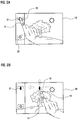
- FIGs. 3A to 3D are display screens illustrating a method of displaying information according to an exemplary embodiment of the present invention. This exemplary embodiment corresponds to the second mode selection method.
- mode indication icons for example, a zoom mode icon 31 and a brightness control mode icon 32
- the mode indication icons 31 and 32 are not provided for a user selection, and simply indicate which mode is selected when the touch area 12 moves in a specific direction.
- the zoom mode icon 31 is assigned to the vertical direction and the brightness control mode icon 32 is assigned to the horizontal direction. If a touch input is generated, the current mode icon 15 is not displayed on the touch screen 10. The current mode icon 15 appears only when the touch area 12 starts to move in any direction.
- the current mode icon 15 indicating a brightness control mode is displayed at the right side of the touch area 12. Additionally, a displacement value 33 indicating the extent of a brightness control is displayed beside the current mode icon 15.
- a display location of the current mode icon 15 may vary according to the movement direction of the touch area 12. For example, the current mode icon 15 is displayed at the right side of the touch area 12 when the touch area 12 moves rightwards, and the current mode icon 15 is displayed at the left side of the touch area 12 when the touch area 12 moves leftwards.
- the current mode icon 15 indicating a zoom in/out mode is displayed above the touch area 12, and a numerical value of the displacement value 33 indicating an extent of enlargement and reduction is displayed beside the current mode icon 15.
- the shape of the current mode icon 15 may vary according to the movement direction of the touch area. For example, if the touch area 12 moves upwards, the shape of the current mode icon 15 may change to a symbol'+' indicating enlargement, and if the touch area 12 moves downwards, the shape of the current mode icon 15 may change to a symbol'-' indicating reduction.
- the current mode is determined according to the movement direction of the touch area 12.
- the current mode is predetermined according to each movement direction, and the corresponding movement direction is displayed at an edge of the mode indication icons 31 and 32 located at the left side of the touch screen 10.
- the movement direction of the touch area 12 may be determined by identifying which of a vertical displacement and a horizontal displacement is greater.
- the displacement is represented as an absolute value regardless of an increasing rate or a decreasing rate of the displacement.
- the current mode is not displayed when the touch area is first moved, but instead the current mode is determined and displayed at the completion of the touch movement.
- the displacement value 33 displayed beside the current mode icon 15 has a function of indicating a maximum value and a minimum value. For example, while zooming in the touch screen 10 by moving the finger 11 upwards, as shown in FIG. 3C , if the displacement value 33 reaches the maximum value of zooming in, the color of the displacement value 33 changes to red to indicate that further enlargement of an image is not possible. When the maximum or minimum value is reached, the displacement value 33 does not change even if the touch area 12 moves further in the same movement direction.
- a plurality of functions in different modes may be executed by changing the movement direction of the finger 11 continuously, as shown in FIG. 3D .
- the finger 11 starts from a first touch area 12a and moves leftward to a second touch area 12b, then moves to a third touch area 12c, and finally moves leftward to a fourth touch area 12d.
- brightness control mode icons 15a and 15b are displayed as the current mode icon and the displacement value 33 indicating brightness is reduced from '09' to '06' respectively.
- the brightness control mode icon 15b disappears and a zoom mode icon 15c appears.
- zoom mode icons 15c and 15d, respectively, showing the displacement value 33 are displayed, and the zoom mode icon 15d disappears when the movement direction of the finger 11 changes to the leftward direction at the third touch area 12c.
- brightness control mode icons 15e and 15f respectively, showing the brightness are displayed.
- FIGs. 4A to 4C are display screens illustrating a method of displaying information according to a non-claimed example. This example corresponds to the second mode selection method. The difference between this example and the previous exemplary embodiment of FIGs. 3A to 3D is that the displacement value is displayed differently, the current mode icon is not displayed, and the mode indication icon first appears and then disappears.
- mode indication icons 41 and 42 are displayed at the left side of the touch screen 10.
- the mode indication icons 41 and 42 individually illustrate a mode assigned to a movement direction.
- the current mode is determined according to the movement direction of the finger 11. At this moment, no current mode icon is displayed, however a function of a selected mode is executed.
- a displacement value is determined according to the movement of the touch area 12 and displayed as a bar 43 and as numerals 44.
- the bar 43 has a shape extending in the movement direction of the finger 11.
- FIG. 4C is another display screen. As shown in FIG. 4C , the displacement value 44 may be displayed as a bar 45 having a graduation indicator 46, and the bar 45 is disposed corresponding to the movement direction of the finger 11, as described above.
- the bars 43 and 45 may be displayed in different forms according to the displacement value.
- the color and thickness of the bars may be set differently.
- a current mode may be determined according to the movement direction of the finger 11 in the example of FIGs. 4A to 4C , or according to the user's selection of a displayed mode indication icon in the example of of FIGs. 2A and 2B .
- the mobile terminal applied to the present invention may be a mobile phone, smart phone, Personal Digital Assistant (PDA), mobile broadcast receiver such as a Digital Multimedia Broadcasting (DMB) receiver, and multimedia player such as an MP3 player and a Portable Multimedia Player (PMP), but is not limited thereto.
- PDA Personal Digital Assistant
- DMB Digital Multimedia Broadcasting
- PMP Portable Multimedia Player
- An exemplary implementation of the present invention may apply to any portable electronic device having a touch screen.
- the touch screen may be formed in the whole area of the mobile terminal or in a partial area at one side of the mobile terminal, and may further be formed at both sides of the mobile terminal.
- the mobile terminal may further include a keypad, a pointing device, and a side button, in addition to the touch screen.
- FIG. 5 is a flowchart illustrating a method of displaying information by using a touch screen input.
- a control unit of the mobile terminal determines whether a touch input is generated by a user through the touch screen 10 at step S51.
- a detecting unit of the touch screen 10 detects the touch input and outputs a signal of the touch input to the control unit. Coordinates of the touch area 12 are included in the signal of the touch input.
- the control unit extracts an outermost coordinate from the coordinates of the touch area 12 at step S52.
- the outermost coordinate may be the uppermost coordinate 13 shown in FIG. 1A .
- a rightmost coordinate or a leftmost coordinate may be extracted instead of the uppermost coordinate 13, as shown in FIGs. 1B and 1C respectively.
- one of the uppermost coordinate, the rightmost coordinate and the leftmost coordinate are used as the outermost coordinate, and extraction of the outermost coordinate is preset according to the user selection.
- the control unit controls to display a current mode icon 15 above the uppermost coordinate 13 maintaining a distance 14 from the uppermost coordinate 13 at step S53.
- the current mode icon 15 is stored in a storage unit and is extracted from the storage unit by the control unit. If the outermost coordinate is extracted as the rightmost coordinate or the leftmost coordinate instead of the uppermost coordinate at step S52, the current mode icon 15 is displayed at the corresponding side of the touch area 12.
- the control unit determines whether the touch input is discontinued from the touch screen 10 at step S54. When the touch input is discontinued from the touch screen 10, the touch screen 10 terminates outputting of a signal to the control unit.
- control unit erases the current mode icon 15 displayed in the touch screen 10 at step S55.
- FIG. 6 is a flowchart illustrating a method of displaying information by using a touch screen input.
- the control unit of the mobile terminal determines whether a mode is selected from the touch screen 10 at step S61.
- a mode indication icons for example, 21 and 22
- the detecting unit of the touch screen 10 detects a touch operation of at least one of the mode indication icons 21 and 22, and outputs a corresponding touch input signal to the control unit.
- the control unit determines whether a further touch input signal is output by the touch screen 10 at step S62.
- the detecting unit of the touch screen 10 detects a touch operation in the touch screen 10 and outputs the touch input signal to the control unit.
- the coordinates of the touch area 12 are included in the touch input signal, and the control unit selects at least one of the uppermost, rightmost and leftmost coordinates of the touch area 12.
- control unit controls to display a current mode icon 15 maintaining a distance from the extracted coordinate at step S63.
- the control unit determines whether the touch area 12 moves at step S64. If the user drags the finger 11 after touching the touch screen 10, the coordinates of the touch area 12 in the touch screen 10 changes accordingly, and thereby the control unit can detect the movement of the touch area 12.
- the control unit extracts a value of movement of the touch area 12 from the changes of the coordinates at step S65.
- the movement of the touch area 12 may be indicated in pixel units.
- the control unit executes a function of the current mode corresponding to the movement of the touch area 12 at step S66.
- the control unit controls to display a displacement value corresponding to the execution of the function at step S67.
- a displacement value corresponding to the execution of the function at step S67.
- the value of y may be displayed in a numeral form.
- control unit determines whether the touch input is discontinued from the touch screen 10 at step S68.
- the touch screen 10 no longer outputs a touch input signal to the control unit.
- control unit erases the current mode icon 15 displayed in the touch screen 10 at step S69.
- FIG. 7 is a flowchart illustrating a method of displaying information by using a touch screen input according to an exemplary embodiment of the present invention.
- the control unit of the mobile terminal determines whether a touch input signal is output by the touch screen 10 at step S71.
- the detecting unit of the touch screen 10 detects a touch operation in the touch screen 10 and outputs a touch input signal to the control unit.
- the coordinates of the touch area 12 are included in the touch input signal.
- the control unit determines whether the touch area 12 moves at step S72. If the user drags the finger 11 after touching the touch screen 10, the coordinates of the touch area 12 transmitted from the touch screen 10 to the control unit change, and thereby the control unit can detect the movement of the touch area 12.
- the control unit extracts a value of movement of the touch area 12 from the changes of the coordinates of the touch area 12 at step S73.
- the movement of the touch area 12 may be indicated, for example, in pixel units, and the coordinates may be divided into an x-coordinate and a y-coordinate.
- the control unit then calculates the movement direction of the touch area 12 from the extracted displacement of the touch area 12 at step S74.
- the movement direction is calculated by comparing each component of the movement in the horizontal direction and in the vertical direction, and by determining which component of the movement is greater.
- the control unit determines a mode corresponding to the calculated movement direction as the current mode at step S75.
- a mode corresponding to each movement direction is predetermined. For example, a zoom in/out mode may be assigned to a vertical movement and a brightness control mode may be assigned to a horizontal movement.
- the control unit executes a function of the current mode corresponding to a value of the movement extracted from the changes of the coordinates of the touch area 12 at step S76.
- the extent of executing a function of the current mode is set according to the movement.
- control unit While executing a function of the current mode corresponding to the displacement, the control unit displays a displacement value 33 and a current mode icon 15 at step S77.
- the control unit determines whether the touch input generated by the touch screen 10 is discontinued at step S78. When the touch input generated by the touch screen 10 is discontinued, the touch screen 10 no longer outputs a touch input signal to the control unit.
- control unit erases the current mode icon 15 displayed in the touch screen 10 at step S79.
- the present invention provides a method of displaying information in a mobile terminal having a touch screen, in which a current mode is determined according to a touch input operation, and at least one of a displacement value generated by executing a function of the current mode and a mode icon indicating the current mode is displayed. Accordingly, when displaying information according to a touch input, changes of information may be displayed distinctively, and thereby user convenience may be improved.
Description
- The present invention relates to a method of displaying information in a mobile terminal having a touch screen. More particularly, the present invention relates to a method of determining a current mode corresponding to a touch input and displaying at least one of a displacement value indicating movement of a touch area and a mode icon indicating the current mode distinctively.
- With developments of information and telecommunication technology and of semiconductor technology, various mobile terminals have become popular. Recent mobile terminals provide various functions, such as multimedia, wireless Internet, short-range radio communication and mobile broadcast functions, in addition to their basic functions of voice communication and character message transmission. More particularly, the size, design, display resolution and user interface of the mobile terminals are being improved.
- According to this trend, methods for applying a touch screen to the mobile terminals are being developed. The touch screen enables both input and display operations to be performed in a single display unit. Because the touch screen can replace the function of a keypad, the size of the touch screen may be increased, and thereby a user may operate the mobile terminals more conveniently. Therefore, research and development of touch screens is very active. However, there remain many areas to be improved for user convenience in using the touch screen.
-
EP 1 615 109 A2 relates to recognizing gestures and using gestures for interacting with software applications. An interactive display table according to this document has a display surface for displaying images and upon or adjacent to which various objects, including a user's hand(s) and finger(s) can be detected. A video camera within the interactive display table responds to infrared (IR) light reflected from the objects to detect any connected components. Connected component correspond to portions of the object(s) that are either in contact, or proximate the display surface. Using these connected components, the interactive display table senses and infers natural hand or finger positions, or movement of an object, to detect gestures. Specific gestures are used to execute applications, carryout functions in an application, create a virtual object, or do other interactions, each of which is associated with a different gesture. A gesture can be a static pose, or a more complex configuration, and/or movement made with one or both hands or other objects. -
US2006036955 A1 discloses a Web page from which the user may issue adaptive viewing commands that cause relevant content to be displayed using additional screen space. - An aim of the present invention is to provide a method of displaying information corresponding to a touch input with improved user convenience in a mobile terminal having a touch screen.
- Another aim of the present invention is to provide a method of displaying changes of information generated by a touch input distinctively in a mobile terminal having a touch screen.
- According to a first aspect of the invention there is provided a method according to claim 1.
- According to a second aspect of the invention there is provided a mobile terminal according to claim 9.
- The above and other aspects, features and advantages of certain exemplary embodiments of the present invention will become more apparent from the following detailed description in conjunction with the accompanying drawings, in which:
-
FIGs. 1A to 1C are diagrams illustrating examples of moving a finger on a touch screen in a method of displaying information in a mobile terminal according to a non-claimed example; -
FIGs. 2A and 2B are display screens illustrating a method of displaying information according to a non-claimed example; -
FIGs. 3A to 3D are display screens illustrating a method of displaying information according to an exemplary embodiment of the present invention; -
FIGs. 4A to 4C are display screens illustrating a method of displaying information according to a non-claimed example; -
FIG. 5 is a flowchart illustrating a method of displaying information by using a touch screen input according to a non-claimed example; -
FIG. 6 is a flowchart illustrating a method of displaying information by using a touch screen input according to a non-claimed example; and -
FIG. 7 is a flowchart illustrating a method of displaying information by using a touch screen input according to an exemplary embodiment of the present invention. - Throughout the drawings, it should be noted that like reference numbers are used to depict the same or similar elements, features and structures.
- The following description with reference to the accompanying drawings is provided to assist in a comprehensive understanding of exemplary embodiments of the present invention as defined by the claims and their equivalents. It includes various specific details to assist in that understanding but these are to be regarded as merely exemplary. Also, descriptions of well-known functions and constructions are omitted for clarity and conciseness.
-
FIGs. 1A to 1C are diagrams illustrating examples of moving a finger on a touch screen. - As shown in
FIG. 1A , if afinger 11 touches atouch screen 10, thetouch screen 10 detects atouch area 12. Thetouch area 12 is a specific area of thetouch screen 10 in which a touch input is generated by a user operation. The coordinates of thetouch area 12 expressed in pixel units are transmitted to a control unit of a mobile terminal, and the control unit extracts anuppermost coordinate 13 of thetouch area 12. The control unit controls to display acurrent mode icon 15 above thetouch area 12 that maintains adistance 14 from theuppermost coordinate 13. Thedistance 14 may be set in pixel units. - The
current mode icon 15 maintains the distance from thetouch area 12 because thetouch area 12 may be obscured by thefinger 11 or by an input device. Thecurrent mode icon 15 is not limited to being displayed at the upper side of thetouch area 12, and can alternatively be displayed at the right and left side of thetouch area 12, as shown inFIGs. 1B and 1C respectively. - If the
touch area 12 moves (i.e. if a user drags thefinger 11 on thetouch screen 10 in a state of touching the touch screen 10), thecurrent mode icon 15 is displayed continuously following the movement of thetouch area 12. However, if thetouch area 12 is deactivated (i.e. if thefinger 11 is released from the touch screen 10), thecurrent mode icon 15 disappears from thetouch screen 10. - The
current mode icon 15 indicates a mode currently in execution. For example, the mode may be a state of a function executed by the mobile terminal, such as a panning mode, a zoom in/out mode, and a brightness control mode of a camera function. The mode may vary according to a type of mobile terminal or a type of application. - A plurality of modes may be displayed in the touch screen, and a mode may be selected from the displayed modes by either of the following two methods. In a first mode selection method, mode indication icons for indicating individual modes are displayed on the touch screen, and a user may select at least one of the displayed mode indication icons. The selectable mode indication icons are different from the
current mode icon 15 in that all selectable mode indication icons are displayed in a specific area (for example, at the left side) of thetouch screen 10. This method will be described later in greater detail. In a second mode selection method, different modes are assigned to each possible movement direction of the finger, and a mode is automatically selected according to the movement direction of the finger. - According to the mode selection method, the
current mode icon 15 is displayed on thetouch screen 10 at different timings related to the selection of a mode. In the first mode selection method, after selection of a mode indication icon, thecurrent mode icon 15 is displayed immediately when a touch input is generated on thetouch screen 10, because the current mode is already determined according to the selected mode indication icon regardless of the movement direction of thetouch area 12. However, in the second mode selection method, the current mode is determined and thecurrent mode icon 15 is displayed only when thetouch area 12 moves after generating a touch input, because the selected current mode is determined according to the movement direction of thetouch area 12. -
FIGs. 2A and 2B are display screens illustrating a method of displaying information. - Referring to
FIG. 2A , mode indication icons (for example, a panningmode icon 21 and a zoom mode icon 22) are displayed at the left side of thetouch screen 10, and entered by selection of the corresponding mode indication icon by the user. For example, if the panningmode icon 21 is selected as shown inFIG. 2A , the mobile terminal enters a panning mode. At this moment, the mode indication icon selected by the user disappears from thetouch screen 10. - When the user again touches the
touch screen 10, the selected mode indication icon reappears at the side of thetouch screen 10, and thecurrent mode icon 15 indicating a panning mode is displayed, as shown inFIG. 2B . Operations of detecting a touch input, extracting an uppermost coordinate of thetouch area 12, and displaying acurrent mode icon 15 maintaining a distance from thetouch area 12 are performed as previously described in relation toFIGs. 1A to 1C . In the panning mode, the user may drag thefinger 11 to move thetouch area 12 displayed on thetouch screen 10 in a desired direction. Thecurrent mode icon 15 is continuously displayed above thetouch area 12 following the movement of thetouch area 12. As the location of thetouch area 12 changes, the mobile terminal repeats the operations of detecting a touch input and extracting an uppermost coordinate of thetouch area 12, and the location of thecurrent mode icon 15 changes accordingly. Technology for moving an image displayed on a touch screen corresponding to movement of a touch area is well known in the art, and thereby is omitted here. - If the user selects a
zoom mode icon 22, the mobile terminal enters a zoom in/out mode. Subsequently, if the user touches thetouch screen 10, a zoom mode icon (not shown) is displayed above thetouch area 12, and if the user drags a finger while in the zoom in/out mode, an image displayed on thetouch screen 10 is enlarged or reduced. The extent of enlargement or reduction is determined by a displacement value of the touch area 12 (e.g. a distance and a direction of finger movement). The extent of enlargement or reduction may be displayed in a numeral form. With the movement of thetouch area 12, the location of thecurrent mode icon 15 changes accordingly. -
FIGs. 3A to 3D are display screens illustrating a method of displaying information according to an exemplary embodiment of the present invention. This exemplary embodiment corresponds to the second mode selection method. - Referring to
FIG. 3A , mode indication icons (for example, azoom mode icon 31 and a brightness control mode icon 32) are displayed at the left side of thetouch screen 10. In contrast to themode indication icons FIGs. 2A and 2B , themode indication icons touch area 12 moves in a specific direction. In the example, thezoom mode icon 31 is assigned to the vertical direction and the brightnesscontrol mode icon 32 is assigned to the horizontal direction. If a touch input is generated, thecurrent mode icon 15 is not displayed on thetouch screen 10. Thecurrent mode icon 15 appears only when thetouch area 12 starts to move in any direction. - If the user touches the
touch screen 10 and drags thefinger 11 as shown inFIG. 3B , thecurrent mode icon 15 indicating a brightness control mode is displayed at the right side of thetouch area 12. Additionally, adisplacement value 33 indicating the extent of a brightness control is displayed beside thecurrent mode icon 15. In the brightness control mode, a display location of thecurrent mode icon 15 may vary according to the movement direction of thetouch area 12. For example, thecurrent mode icon 15 is displayed at the right side of thetouch area 12 when thetouch area 12 moves rightwards, and thecurrent mode icon 15 is displayed at the left side of thetouch area 12 when thetouch area 12 moves leftwards. - If the user drags the
finger 11 upwards after touching thetouch screen 10, as shown inFIG. 3C , thecurrent mode icon 15 indicating a zoom in/out mode is displayed above thetouch area 12, and a numerical value of thedisplacement value 33 indicating an extent of enlargement and reduction is displayed beside thecurrent mode icon 15. In the zoom in/out mode, the shape of thecurrent mode icon 15 may vary according to the movement direction of the touch area. For example, if thetouch area 12 moves upwards, the shape of thecurrent mode icon 15 may change to a symbol'+' indicating enlargement, and if thetouch area 12 moves downwards, the shape of thecurrent mode icon 15 may change to a symbol'-' indicating reduction. - As described above, the current mode is determined according to the movement direction of the
touch area 12. The current mode is predetermined according to each movement direction, and the corresponding movement direction is displayed at an edge of themode indication icons touch screen 10. The movement direction of thetouch area 12 may be determined by identifying which of a vertical displacement and a horizontal displacement is greater. The displacement is represented as an absolute value regardless of an increasing rate or a decreasing rate of the displacement. In the case that the vertical displacement and the horizontal displacement have the same value at the beginning of movement, the current mode is not displayed when the touch area is first moved, but instead the current mode is determined and displayed at the completion of the touch movement. - The
displacement value 33 displayed beside thecurrent mode icon 15 has a function of indicating a maximum value and a minimum value. For example, while zooming in thetouch screen 10 by moving thefinger 11 upwards, as shown inFIG. 3C , if thedisplacement value 33 reaches the maximum value of zooming in, the color of thedisplacement value 33 changes to red to indicate that further enlargement of an image is not possible. When the maximum or minimum value is reached, thedisplacement value 33 does not change even if thetouch area 12 moves further in the same movement direction. - In an exemplary implementation, a plurality of functions in different modes may be executed by changing the movement direction of the
finger 11 continuously, as shown inFIG. 3D . In the implementation, thefinger 11 starts from afirst touch area 12a and moves leftward to asecond touch area 12b, then moves to athird touch area 12c, and finally moves leftward to afourth touch area 12d. - As the
finger 11 moves leftwards from thefirst touch area 12a to thesecond touch area 12b, brightnesscontrol mode icons displacement value 33 indicating brightness is reduced from '09' to '06' respectively. When the movement direction of thefinger 11 changes to the downward direction at thesecond touch area 12b, the brightnesscontrol mode icon 15b disappears and azoom mode icon 15c appears. When moving from thesecond touch area 12b to thethird touch area 12c,zoom mode icons displacement value 33 are displayed, and thezoom mode icon 15d disappears when the movement direction of thefinger 11 changes to the leftward direction at thethird touch area 12c. When moving from thethird touch area 12c to thefourth touch area 12d, brightnesscontrol mode icons -
FIGs. 4A to 4C are display screens illustrating a method of displaying information according to a non-claimed example. This example corresponds to the second mode selection method. The difference between this example and the previous exemplary embodiment ofFIGs. 3A to 3D is that the displacement value is displayed differently, the current mode icon is not displayed, and the mode indication icon first appears and then disappears. - Referring to
FIG. 4A ,mode indication icons touch screen 10. Themode indication icons - Referring to
FIG. 4B , if thefinger 11 touches thetouch screen 10 and drags in a specific direction, the current mode is determined according to the movement direction of thefinger 11. At this moment, no current mode icon is displayed, however a function of a selected mode is executed. A displacement value is determined according to the movement of thetouch area 12 and displayed as abar 43 and asnumerals 44. Thebar 43 has a shape extending in the movement direction of thefinger 11. When thebar 43 anddisplacement value 44 appear, themode indication icons FIG. 4A disappear from thetouch screen 10. -
FIG. 4C is another display screen. As shown inFIG. 4C , thedisplacement value 44 may be displayed as abar 45 having agraduation indicator 46, and thebar 45 is disposed corresponding to the movement direction of thefinger 11, as described above. - As shown in
FIGs. 4B and4C , thebars - A current mode may be determined according to the movement direction of the
finger 11 in the example ofFIGs. 4A to 4C , or according to the user's selection of a displayed mode indication icon in the example of ofFIGs. 2A and 2B . - Hereinafter, a method of displaying information according to an exemplary embodiment of the present invention is described in relation to an internal operation of the mobile terminal.
- The mobile terminal applied to the present invention may be a mobile phone, smart phone, Personal Digital Assistant (PDA), mobile broadcast receiver such as a Digital Multimedia Broadcasting (DMB) receiver, and multimedia player such as an MP3 player and a Portable Multimedia Player (PMP), but is not limited thereto. An exemplary implementation of the present invention may apply to any portable electronic device having a touch screen. The touch screen may be formed in the whole area of the mobile terminal or in a partial area at one side of the mobile terminal, and may further be formed at both sides of the mobile terminal. The mobile terminal may further include a keypad, a pointing device, and a side button, in addition to the touch screen.
-
FIG. 5 is a flowchart illustrating a method of displaying information by using a touch screen input. - Referring to
FIGs. 1A to 1C , andFIG. 5 , a control unit of the mobile terminal determines whether a touch input is generated by a user through thetouch screen 10 at step S51. A detecting unit of thetouch screen 10 detects the touch input and outputs a signal of the touch input to the control unit. Coordinates of thetouch area 12 are included in the signal of the touch input. - If a touch input is generated by a user, the control unit extracts an outermost coordinate from the coordinates of the
touch area 12 at step S52. The outermost coordinate may be the uppermost coordinate 13 shown inFIG. 1A . Alternatively, a rightmost coordinate or a leftmost coordinate may be extracted instead of the uppermost coordinate 13, as shown inFIGs. 1B and 1C respectively. In this specification, one of the uppermost coordinate, the rightmost coordinate and the leftmost coordinate are used as the outermost coordinate, and extraction of the outermost coordinate is preset according to the user selection. - The control unit controls to display a
current mode icon 15 above the uppermost coordinate 13 maintaining adistance 14 from the uppermost coordinate 13 at step S53. Thecurrent mode icon 15 is stored in a storage unit and is extracted from the storage unit by the control unit. If the outermost coordinate is extracted as the rightmost coordinate or the leftmost coordinate instead of the uppermost coordinate at step S52, thecurrent mode icon 15 is displayed at the corresponding side of thetouch area 12. - After displaying the
current mode icon 15, the control unit determines whether the touch input is discontinued from thetouch screen 10 at step S54. When the touch input is discontinued from thetouch screen 10, thetouch screen 10 terminates outputting of a signal to the control unit. - If the touch input is discontinued at step S54, the control unit erases the
current mode icon 15 displayed in thetouch screen 10 at step S55. -
FIG. 6 is a flowchart illustrating a method of displaying information by using a touch screen input. - Referring to
FIGs. 2A and 2B , andFIG. 6 , the control unit of the mobile terminal determines whether a mode is selected from thetouch screen 10 at step S61. In thetouch screen 10, a plurality of mode indication icons (for example, 21 and 22) are displayed, and the detecting unit of thetouch screen 10 detects a touch operation of at least one of themode indication icons - If a mode is selected, the control unit determines whether a further touch input signal is output by the
touch screen 10 at step S62. The detecting unit of thetouch screen 10 detects a touch operation in thetouch screen 10 and outputs the touch input signal to the control unit. The coordinates of thetouch area 12 are included in the touch input signal, and the control unit selects at least one of the uppermost, rightmost and leftmost coordinates of thetouch area 12. - If a further touch input signal is output, the control unit controls to display a
current mode icon 15 maintaining a distance from the extracted coordinate at step S63. - The control unit then determines whether the
touch area 12 moves at step S64. If the user drags thefinger 11 after touching thetouch screen 10, the coordinates of thetouch area 12 in thetouch screen 10 changes accordingly, and thereby the control unit can detect the movement of thetouch area 12. - If the
touch area 12 moves, the control unit extracts a value of movement of thetouch area 12 from the changes of the coordinates at step S65. The movement of thetouch area 12 may be indicated in pixel units. - After extracting the movement of the
touch area 12, the control unit executes a function of the current mode corresponding to the movement of thetouch area 12 at step S66. Executing a function of the current mode may be predetermined according to the movement of thetouch area 12. For example, if the current mode is a zoom in/out mode, the enlargement ratio of zooming may be set to y times corresponding to a movement of x pixels of thetouch area 12 in the upward direction, according to a relationship between x and y, e.g. y = mx, where m is a constant. - While executing a function corresponding to the movement of the
touch area 12, the control unit controls to display a displacement value corresponding to the execution of the function at step S67. For example, when the movement of the touch area is x pixels and the display screen is enlarged by y times, the value of y may be displayed in a numeral form. - Subsequently, the control unit determines whether the touch input is discontinued from the
touch screen 10 at step S68. When the touch input is discontinued from thetouch screen 10, thetouch screen 10 no longer outputs a touch input signal to the control unit. - If the touch input generated by the
touch screen 10 is discontinued at step S68, the control unit erases thecurrent mode icon 15 displayed in thetouch screen 10 at step S69. -
FIG. 7 is a flowchart illustrating a method of displaying information by using a touch screen input according to an exemplary embodiment of the present invention. - Referring to
FIGs. 3A to 3D , andFIG. 7 , the control unit of the mobile terminal determines whether a touch input signal is output by thetouch screen 10 at step S71. The detecting unit of thetouch screen 10 detects a touch operation in thetouch screen 10 and outputs a touch input signal to the control unit. The coordinates of thetouch area 12 are included in the touch input signal. - If a touch input signal is output, the control unit determines whether the
touch area 12 moves at step S72. If the user drags thefinger 11 after touching thetouch screen 10, the coordinates of thetouch area 12 transmitted from thetouch screen 10 to the control unit change, and thereby the control unit can detect the movement of thetouch area 12. - If the
touch area 12 moves, the control unit extracts a value of movement of thetouch area 12 from the changes of the coordinates of thetouch area 12 at step S73. The movement of thetouch area 12 may be indicated, for example, in pixel units, and the coordinates may be divided into an x-coordinate and a y-coordinate. - The control unit then calculates the movement direction of the
touch area 12 from the extracted displacement of thetouch area 12 at step S74. The movement direction is calculated by comparing each component of the movement in the horizontal direction and in the vertical direction, and by determining which component of the movement is greater. - The control unit determines a mode corresponding to the calculated movement direction as the current mode at step S75. A mode corresponding to each movement direction is predetermined. For example, a zoom in/out mode may be assigned to a vertical movement and a brightness control mode may be assigned to a horizontal movement.
- The control unit executes a function of the current mode corresponding to a value of the movement extracted from the changes of the coordinates of the
touch area 12 at step S76. The extent of executing a function of the current mode is set according to the movement. - While executing a function of the current mode corresponding to the displacement, the control unit displays a
displacement value 33 and acurrent mode icon 15 at step S77. - The control unit determines whether the touch input generated by the
touch screen 10 is discontinued at step S78. When the touch input generated by thetouch screen 10 is discontinued, thetouch screen 10 no longer outputs a touch input signal to the control unit. - If the touch input is discontinued at step S78, the control unit erases the
current mode icon 15 displayed in thetouch screen 10 at step S79. - As described above, the present invention provides a method of displaying information in a mobile terminal having a touch screen, in which a current mode is determined according to a touch input operation, and at least one of a displacement value generated by executing a function of the current mode and a mode icon indicating the current mode is displayed. Accordingly, when displaying information according to a touch input, changes of information may be displayed distinctively, and thereby user convenience may be improved.
- Although exemplary embodiments of the present invention have been shown and described in detail hereinabove, it should be understood by those skilled in the art that various changes in form and details, many displacement values and modifications of the basic inventive concept herein described will still fall within the scope of the present invention as defined in the appended claims.
Claims (15)
- A method of displaying information in a mobile terminal, the method comprising:determining (S71) whether a touch input is generated by a touch screen (10);determining (S72), if the touch input is generated by a touch screen, whether a touch area (12) moves;calculating (S74), if the touch area moves, a movement direction of the touch area by extracting (S73) a value of the touch area movement;determining (S75) a current mode according to the calculated movement direction of the touch area;executing (S76) a function of the current mode corresponding to the extracted value of the touch area movement; and characterised in that the method further comprises:
displaying (S77), while executing the function of the current mode, a displacement value (33) generated by executing the function of the current mode and a current mode icon (15) indicating the current mode;wherein the displaying of the displacement value and the current mode icon comprises:extracting an outermost coordinate from the coordinates of the touch area; anddisplaying the current mode icon and the displacement value maintaining a distance from the extracted outermost coordinate;determining (S78), after displaying at least one of a displacement value generated by executing the function of the current mode and a current mode icon indicating the current mode, whether the touch input generated by the touch screen is discontinued; anderasing (S79), if the touch input generated by the touch screen is discontinued, the current mode icon and the displacement value. - The method of claim 1, wherein the current mode is set to a first mode if the calculated movement direction is a vertical direction and to a second mode if the calculated movement direction is a horizontal direction.
- The method of claim 1, wherein the displacement value (33) is displayed in a numeral form.
- The method of claim 1, further comprising displaying the displacement value (33) in a numeral form beside the current mode icon (15).
- The method of claim 1, wherein the outermost coordinate comprises at least one of the uppermost coordinate, the leftmost coordinate and the rightmost coordinate of the touch area (12).
- The method of claim 1, further comprising displaying, before determining whether a touch input is generated, mode indication icons of individual movement directions.
- The method of claim 6, wherein the mode indication icons disappear when a displacement value (33) is displayed.
- The method of claim 1, wherein the executing (S76) the function of the current mode corresponding to the extracted value further comprises:calculating, if a touch area moves in a further direction, a further movement direction of the touch area by extracting a value of the touch area movement;determining a further current mode according to the calculated further movement direction of the touch area; andexecuting a function of the further current mode corresponding to the extracted value of the touch area movement.
- A mobile terminal having a touch screen (10), the mobile terminal configured to:determine (S71) whether a touch input is generated by the touch screen;determine (S72), if a the touch input is generated by a touch screen, whether a touch area (12) moves;calculate (S74), if the touch area moves, a movement direction of the touch area by extracting (S73) a value of the touch area movement;determine (S75) a current mode according to the calculated movement direction of the touch area;execute (S76) a function of the current mode corresponding to the extracted value of the touch area movement; and characterised in that the mobile terminal is further configured to:
display (S77), while executing the function of the current mode, a displacement value (33) generated by executing the function of the current mode and a current mode icon (15) indicating the current mode on the touch screen;wherein the displaying of the displacement value and the current mode icon comprises:extracting an outermost coordinate from the coordinates of the touch area; anddisplaying the current mode icon and the displacement value maintaining a distance from the extracted outermost coordinate;determine (S78), after displaying at least one of a displacement value generated by executing the function of the current mode and a current mode icon indicating the current mode, whether the touch input generated by the touch screen is discontinued; anderase (S79), if the touch input generated by the touch screen is discontinued, the current mode icon and the displacement value from the touch screen. - The mobile terminal of claim 9, wherein the current mode is set to a first mode if the calculated movement direction is a vertical direction and to a second mode if the calculated movement direction is a horizontal direction.
- The mobile terminal of claim 9, wherein the displacement value (33) is displayed in a numeral form.
- The mobile terminal of claim 9, wherein the mobile terminal is further configured to:
display the displacement value (33) in a numeral form beside the current mode icon (15). - The mobile terminal of claim 9, wherein the outermost coordinate comprises at least one of the uppermost coordinate, the leftmost coordinate and the rightmost coordinate of the touch area (12).
- The mobile terminal of claim 9, wherein the mobile terminal is further configured to:
display, before determining whether a touch input is generated, mode indication icons of individual movement directions. - The mobile terminal of claim 9, wherein the mobile terminal is further configured to:calculate, if a touch area moves in a further direction, a further movement direction of the touch area by extracting a value of the touch area movement;determine a further current mode according to the calculated further movement direction of the touch area; andexecute a function of the further current mode corresponding to the extracted value of the touch area movement.
Applications Claiming Priority (2)
| Application Number | Priority Date | Filing Date | Title |
|---|---|---|---|
| KR1020070014409A KR100785071B1 (en) | 2007-02-08 | 2007-02-12 | Method for displaying information in response to touch input in mobile device with touchscreen |
| EP08000635A EP1956474A3 (en) | 2007-02-12 | 2008-01-15 | Method of displaying information by using touch input in a mobile terminal |
Related Parent Applications (1)
| Application Number | Title | Priority Date | Filing Date |
|---|---|---|---|
| EP08000635A Division EP1956474A3 (en) | 2007-02-12 | 2008-01-15 | Method of displaying information by using touch input in a mobile terminal |
Publications (2)
| Publication Number | Publication Date |
|---|---|
| EP3404520A1 EP3404520A1 (en) | 2018-11-21 |
| EP3404520B1 true EP3404520B1 (en) | 2021-12-15 |
Family
ID=39055658
Family Applications (2)
| Application Number | Title | Priority Date | Filing Date |
|---|---|---|---|
| EP08000635A Ceased EP1956474A3 (en) | 2007-02-12 | 2008-01-15 | Method of displaying information by using touch input in a mobile terminal |
| EP18175402.9A Active EP3404520B1 (en) | 2007-02-12 | 2008-01-15 | Method of displaying information by using touch input in mobile terminal |
Family Applications Before (1)
| Application Number | Title | Priority Date | Filing Date |
|---|---|---|---|
| EP08000635A Ceased EP1956474A3 (en) | 2007-02-12 | 2008-01-15 | Method of displaying information by using touch input in a mobile terminal |
Country Status (4)
| Country | Link |
|---|---|
| US (2) | US8493333B2 (en) |
| EP (2) | EP1956474A3 (en) |
| KR (1) | KR100785071B1 (en) |
| CN (1) | CN101246413B (en) |
Families Citing this family (54)
| Publication number | Priority date | Publication date | Assignee | Title |
|---|---|---|---|---|
| US20090122018A1 (en) * | 2007-11-12 | 2009-05-14 | Leonid Vymenets | User Interface for Touchscreen Device |
| KR101546774B1 (en) * | 2008-07-29 | 2015-08-24 | 엘지전자 주식회사 | Mobile terminal and operation control method thereof |
| GB2464094A (en) * | 2008-09-30 | 2010-04-07 | Rapid Mobile Media Ltd | Method and apparatus for displaying content at a mobile device |
| KR101517082B1 (en) * | 2008-11-10 | 2015-04-30 | 엘지전자 주식회사 | Mobile terminal using flexible display and operation method thereof |
| US8184102B2 (en) * | 2008-12-17 | 2012-05-22 | Cypress Semiconductor Corporation | Finger gesture recognition for touch sensing surface |
| KR101563523B1 (en) * | 2009-01-30 | 2015-10-28 | 삼성전자주식회사 | Mobile terminal having dual touch screen and method for displaying user interface thereof |
| TW201032101A (en) * | 2009-02-26 | 2010-09-01 | Qisda Corp | Electronic device controlling method |
| KR101857564B1 (en) * | 2009-05-15 | 2018-05-15 | 삼성전자 주식회사 | Method for processing image of mobile terminal |
| KR101576292B1 (en) * | 2009-05-21 | 2015-12-09 | 엘지전자 주식회사 | The method for executing menu in mobile terminal and mobile terminal using the same |
| KR101636705B1 (en) * | 2009-08-06 | 2016-07-06 | 삼성전자주식회사 | Method and apparatus for inputting letter in portable terminal having a touch screen |
| KR101024139B1 (en) | 2009-09-24 | 2011-03-22 | 삼성에스디에스 주식회사 | Method for displaying in terminal device |
| KR101600091B1 (en) * | 2009-11-25 | 2016-03-04 | 엘지전자 주식회사 | Method for displaying data in mobile terminal having touch screen and mobile termimnal thereof |
| JP5506375B2 (en) * | 2009-12-25 | 2014-05-28 | キヤノン株式会社 | Information processing apparatus and control method thereof |
| US8977987B1 (en) * | 2010-06-14 | 2015-03-10 | Google Inc. | Motion-based interface control on computing device |
| KR20120023867A (en) * | 2010-09-02 | 2012-03-14 | 삼성전자주식회사 | Mobile terminal having touch screen and method for displaying contents thereof |
| CN102446032B (en) * | 2010-09-30 | 2014-09-17 | 中国移动通信有限公司 | Information input method and terminal based on camera |
| CN102479027A (en) * | 2010-11-24 | 2012-05-30 | 中兴通讯股份有限公司 | Control method and device of application icons on touch screen |
| CN102566858B (en) * | 2010-12-09 | 2014-12-03 | 联想(北京)有限公司 | Touch control method and electronic equipment |
| US8514192B2 (en) * | 2011-01-04 | 2013-08-20 | Ma Lighting Technology Gmbh | Method for operating a lighting control console |
| CN102760025A (en) * | 2011-04-26 | 2012-10-31 | 富泰华工业(深圳)有限公司 | Image browsing system, and image zooming method and image switching method |
| CN102253746B (en) | 2011-06-23 | 2017-05-03 | 中兴通讯股份有限公司 | Information processing method and equipment for electronic equipment with touch screen |
| JP5325943B2 (en) * | 2011-07-12 | 2013-10-23 | 富士フイルム株式会社 | Information processing apparatus, information processing method, and program |
| KR101924835B1 (en) * | 2011-10-10 | 2018-12-05 | 삼성전자주식회사 | Method and apparatus for function of touch device |
| TWI456486B (en) * | 2012-03-06 | 2014-10-11 | Acer Inc | Electronic apparatus and method for controlling the same |
| JP2013239147A (en) * | 2012-04-20 | 2013-11-28 | Ricoh Co Ltd | Display control device |
| US20130285927A1 (en) * | 2012-04-30 | 2013-10-31 | Research In Motion Limited | Touchscreen keyboard with correction of previously input text |
| CN102929481A (en) * | 2012-10-09 | 2013-02-13 | 中兴通讯股份有限公司南京分公司 | User interface display method and device |
| CN104346065B (en) * | 2013-08-09 | 2017-12-29 | 联想(北京)有限公司 | A kind of data processing method and device |
| TWI600322B (en) | 2014-09-02 | 2017-09-21 | 蘋果公司 | Method for operating an electronic device with an integratd camera and related electronic device and non-transitory computer readable storage medium |
| KR20160027801A (en) * | 2014-09-02 | 2016-03-10 | 삼성전자주식회사 | Display apparatus comprising lighting bezel and method for providing visual feedback by using the same |
| EP3286915B1 (en) | 2015-04-23 | 2021-12-08 | Apple Inc. | Digital viewfinder user interface for multiple cameras |
| US20160314559A1 (en) * | 2015-04-24 | 2016-10-27 | Kabushiki Kaisha Toshiba | Electronic apparatus and method |
| KR20170036424A (en) * | 2015-09-24 | 2017-04-03 | 삼성전자주식회사 | Method for providing event corresponding to touch attribute and electronic device thereof |
| USD825523S1 (en) | 2016-01-06 | 2018-08-14 | I.Am.Plus, Llc | Set of earbuds |
| KR102481632B1 (en) * | 2016-04-26 | 2022-12-28 | 삼성전자주식회사 | Electronic device and method for inputting adaptive touch using display in the electronic device |
| US10009536B2 (en) | 2016-06-12 | 2018-06-26 | Apple Inc. | Applying a simulated optical effect based on data received from multiple camera sensors |
| JP6808529B2 (en) | 2017-02-14 | 2021-01-06 | キヤノン株式会社 | Imaging device and its control method |
| JP6914669B2 (en) * | 2017-02-14 | 2021-08-04 | キヤノン株式会社 | Imaging device and its control method |
| US10134158B2 (en) | 2017-02-23 | 2018-11-20 | Microsoft Technology Licensing, Llc | Directional stamping |
| DK180859B1 (en) | 2017-06-04 | 2022-05-23 | Apple Inc | USER INTERFACE CAMERA EFFECTS |
| US11112964B2 (en) | 2018-02-09 | 2021-09-07 | Apple Inc. | Media capture lock affordance for graphical user interface |
| US11722764B2 (en) | 2018-05-07 | 2023-08-08 | Apple Inc. | Creative camera |
| US10375313B1 (en) | 2018-05-07 | 2019-08-06 | Apple Inc. | Creative camera |
| DK201870623A1 (en) | 2018-09-11 | 2020-04-15 | Apple Inc. | User interfaces for simulated depth effects |
| US11770601B2 (en) | 2019-05-06 | 2023-09-26 | Apple Inc. | User interfaces for capturing and managing visual media |
| US10674072B1 (en) | 2019-05-06 | 2020-06-02 | Apple Inc. | User interfaces for capturing and managing visual media |
| US11128792B2 (en) | 2018-09-28 | 2021-09-21 | Apple Inc. | Capturing and displaying images with multiple focal planes |
| US11321857B2 (en) | 2018-09-28 | 2022-05-03 | Apple Inc. | Displaying and editing images with depth information |
| US11706521B2 (en) | 2019-05-06 | 2023-07-18 | Apple Inc. | User interfaces for capturing and managing visual media |
| US11039074B1 (en) | 2020-06-01 | 2021-06-15 | Apple Inc. | User interfaces for managing media |
| US11212449B1 (en) | 2020-09-25 | 2021-12-28 | Apple Inc. | User interfaces for media capture and management |
| US11539876B2 (en) | 2021-04-30 | 2022-12-27 | Apple Inc. | User interfaces for altering visual media |
| US11778339B2 (en) | 2021-04-30 | 2023-10-03 | Apple Inc. | User interfaces for altering visual media |
| JP2023001762A (en) * | 2021-06-21 | 2023-01-06 | 株式会社アニプレックス | Program and information for providing game to player |
Family Cites Families (13)
| Publication number | Priority date | Publication date | Assignee | Title |
|---|---|---|---|---|
| JP3744116B2 (en) | 1997-04-08 | 2006-02-08 | 松下電器産業株式会社 | Display input device |
| US20040090423A1 (en) * | 1998-02-27 | 2004-05-13 | Logitech Europe S.A. | Remote controlled video display GUI using 2-directional pointing |
| JPH11355617A (en) * | 1998-06-05 | 1999-12-24 | Fuji Photo Film Co Ltd | Camera with image display device |
| US6411283B1 (en) * | 1999-05-20 | 2002-06-25 | Micron Technology, Inc. | Computer touch screen adapted to facilitate selection of features at edge of screen |
| JP2003005912A (en) * | 2001-06-20 | 2003-01-10 | Hitachi Ltd | Display device with touch panel and display method |
| JP2007512610A (en) * | 2003-11-27 | 2007-05-17 | コーニンクレッカ フィリップス エレクトロニクス エヌ ヴィ | How to visualize a pointer during a conversation |
| JP2005335156A (en) * | 2004-05-26 | 2005-12-08 | Matsushita Electric Ind Co Ltd | Display system, electronic blackboard system, and display control method |
| US7519223B2 (en) * | 2004-06-28 | 2009-04-14 | Microsoft Corporation | Recognizing gestures and using gestures for interacting with software applications |
| JP2006047602A (en) * | 2004-08-04 | 2006-02-16 | Casio Comput Co Ltd | Camera device |
| US7721197B2 (en) | 2004-08-12 | 2010-05-18 | Microsoft Corporation | System and method of displaying content on small screen computing devices |
| KR101058011B1 (en) | 2004-10-01 | 2011-08-19 | 삼성전자주식회사 | How to Operate Digital Camera Using Touch Screen |
| KR100686562B1 (en) | 2005-12-02 | 2007-02-26 | 유대성 | Apparatus for controlling display in electronic device |
| US7770136B2 (en) * | 2007-01-24 | 2010-08-03 | Microsoft Corporation | Gesture recognition interactive feedback |
-
2007
- 2007-02-12 KR KR1020070014409A patent/KR100785071B1/en active IP Right Grant
-
2008
- 2008-01-10 US US11/972,141 patent/US8493333B2/en active Active
- 2008-01-15 EP EP08000635A patent/EP1956474A3/en not_active Ceased
- 2008-01-15 EP EP18175402.9A patent/EP3404520B1/en active Active
- 2008-01-24 CN CN200810008813XA patent/CN101246413B/en active Active
-
2013
- 2013-07-23 US US13/948,474 patent/US20130300702A1/en not_active Abandoned
Non-Patent Citations (1)
| Title |
|---|
| None * |
Also Published As
| Publication number | Publication date |
|---|---|
| CN101246413B (en) | 2010-10-27 |
| CN101246413A (en) | 2008-08-20 |
| EP1956474A2 (en) | 2008-08-13 |
| KR100785071B1 (en) | 2007-12-12 |
| US8493333B2 (en) | 2013-07-23 |
| US20080192020A1 (en) | 2008-08-14 |
| EP3404520A1 (en) | 2018-11-21 |
| EP1956474A3 (en) | 2011-10-26 |
| US20130300702A1 (en) | 2013-11-14 |
Similar Documents
| Publication | Publication Date | Title |
|---|---|---|
| EP3404520B1 (en) | Method of displaying information by using touch input in mobile terminal | |
| US10928993B2 (en) | Device, method, and graphical user interface for manipulating workspace views | |
| JP5946462B2 (en) | Mobile terminal and its screen control method | |
| US9467729B2 (en) | Method for remotely controlling smart television | |
| JP5721662B2 (en) | Input receiving method, input receiving program, and input device | |
| US10162480B2 (en) | Information processing apparatus, information processing method, program, and information processing system | |
| KR101915615B1 (en) | Apparatus and method for controlling user interface based motion | |
| US20120044173A1 (en) | Information processing device, computer program product, and display control method | |
| US20050223342A1 (en) | Method of navigating in application views, electronic device, graphical user interface and computer program product | |
| MX2007008429A (en) | Mobile electronic apparatus with touch input device and display method using the same . | |
| KR20140136500A (en) | Touch screen hover input handling | |
| KR101929316B1 (en) | Method and apparatus for displaying keypad in terminal having touchscreen | |
| CN104932809A (en) | Device and method for controlling a display panel | |
| US20110227844A1 (en) | Method and apparatus for inputting character in portable terminal | |
| CN108595076A (en) | A kind of electronic equipment touch-control exchange method | |
| CN108459790A (en) | A kind of electronic equipment touch-control exchange method | |
| KR100795590B1 (en) | Method of navigating, electronic device, user interface and computer program product | |
| CN108595075A (en) | A kind of electronic equipment touch-control exchange method | |
| KR101432483B1 (en) | Method for controlling a touch screen using control area and terminal using the same | |
| US20070006086A1 (en) | Method of browsing application views, electronic device, graphical user interface and computer program product | |
| CN108563379A (en) | A kind of electronic equipment touch-control exchange method | |
| US10983686B2 (en) | Display control apparatus equipped with touch panel, control method therefor, and storage medium storing control program therefor | |
| JP5449088B2 (en) | Information input device | |
| JP2015102946A (en) | Information processing apparatus, control method of information processing apparatus, and program | |
| JP2023003565A (en) | Display controller and control method thereof |
Legal Events
| Date | Code | Title | Description |
|---|---|---|---|
| PUAI | Public reference made under article 153(3) epc to a published international application that has entered the european phase |
Free format text: ORIGINAL CODE: 0009012 |
|
| STAA | Information on the status of an ep patent application or granted ep patent |
Free format text: STATUS: THE APPLICATION HAS BEEN PUBLISHED |
|
| AC | Divisional application: reference to earlier application |
Ref document number: 1956474 Country of ref document: EP Kind code of ref document: P |
|
| AK | Designated contracting states |
Kind code of ref document: A1 Designated state(s): DE FR GB |
|
| STAA | Information on the status of an ep patent application or granted ep patent |
Free format text: STATUS: REQUEST FOR EXAMINATION WAS MADE |
|
| 17P | Request for examination filed |
Effective date: 20190520 |
|
| RBV | Designated contracting states (corrected) |
Designated state(s): DE FR GB |
|
| STAA | Information on the status of an ep patent application or granted ep patent |
Free format text: STATUS: EXAMINATION IS IN PROGRESS |
|
| 17Q | First examination report despatched |
Effective date: 20191016 |
|
| STAA | Information on the status of an ep patent application or granted ep patent |
Free format text: STATUS: EXAMINATION IS IN PROGRESS |
|
| GRAP | Despatch of communication of intention to grant a patent |
Free format text: ORIGINAL CODE: EPIDOSNIGR1 |
|
| STAA | Information on the status of an ep patent application or granted ep patent |
Free format text: STATUS: GRANT OF PATENT IS INTENDED |
|
| INTG | Intention to grant announced |
Effective date: 20210713 |
|
| GRAS | Grant fee paid |
Free format text: ORIGINAL CODE: EPIDOSNIGR3 |
|
| GRAA | (expected) grant |
Free format text: ORIGINAL CODE: 0009210 |
|
| STAA | Information on the status of an ep patent application or granted ep patent |
Free format text: STATUS: THE PATENT HAS BEEN GRANTED |
|
| AC | Divisional application: reference to earlier application |
Ref document number: 1956474 Country of ref document: EP Kind code of ref document: P |
|
| AK | Designated contracting states |
Kind code of ref document: B1 Designated state(s): DE FR GB |
|
| REG | Reference to a national code |
Ref country code: GB Ref legal event code: FG4D |
|
| REG | Reference to a national code |
Ref country code: DE Ref legal event code: R096 Ref document number: 602008064337 Country of ref document: DE |
|
| REG | Reference to a national code |
Ref country code: DE Ref legal event code: R097 Ref document number: 602008064337 Country of ref document: DE |
|
| PLBE | No opposition filed within time limit |
Free format text: ORIGINAL CODE: 0009261 |
|
| STAA | Information on the status of an ep patent application or granted ep patent |
Free format text: STATUS: NO OPPOSITION FILED WITHIN TIME LIMIT |
|
| 26N | No opposition filed |
Effective date: 20220916 |
|
| PG25 | Lapsed in a contracting state [announced via postgrant information from national office to epo] |
Ref country code: FR Free format text: LAPSE BECAUSE OF NON-PAYMENT OF DUE FEES Effective date: 20220215 |
|
| PGFP | Annual fee paid to national office [announced via postgrant information from national office to epo] |
Ref country code: DE Payment date: 20221220 Year of fee payment: 16 |
|
| PGFP | Annual fee paid to national office [announced via postgrant information from national office to epo] |
Ref country code: GB Payment date: 20231220 Year of fee payment: 17 |