EP3404482A1 - Device for protecting an optical sensor and associated driving-assistance system - Google Patents
Device for protecting an optical sensor and associated driving-assistance system Download PDFInfo
- Publication number
- EP3404482A1 EP3404482A1 EP18171905.5A EP18171905A EP3404482A1 EP 3404482 A1 EP3404482 A1 EP 3404482A1 EP 18171905 A EP18171905 A EP 18171905A EP 3404482 A1 EP3404482 A1 EP 3404482A1
- Authority
- EP
- European Patent Office
- Prior art keywords
- optical element
- optical sensor
- optical
- housing
- motor
- Prior art date
- Legal status (The legal status is an assumption and is not a legal conclusion. Google has not performed a legal analysis and makes no representation as to the accuracy of the status listed.)
- Withdrawn
Links
- 230000003287 optical effect Effects 0.000 title claims abstract description 234
- 238000011144 upstream manufacturing Methods 0.000 claims abstract description 10
- 230000001681 protective effect Effects 0.000 claims description 19
- 238000009833 condensation Methods 0.000 description 7
- 239000012528 membrane Substances 0.000 description 7
- XLYOFNOQVPJJNP-UHFFFAOYSA-N water Substances O XLYOFNOQVPJJNP-UHFFFAOYSA-N 0.000 description 7
- 239000011324 bead Substances 0.000 description 4
- 238000004140 cleaning Methods 0.000 description 4
- 230000002209 hydrophobic effect Effects 0.000 description 4
- 238000000576 coating method Methods 0.000 description 3
- 230000005494 condensation Effects 0.000 description 3
- 230000000694 effects Effects 0.000 description 3
- 239000003344 environmental pollutant Substances 0.000 description 3
- 231100000719 pollutant Toxicity 0.000 description 3
- 239000011248 coating agent Substances 0.000 description 2
- 230000008021 deposition Effects 0.000 description 2
- 238000001514 detection method Methods 0.000 description 2
- 239000011521 glass Substances 0.000 description 2
- 229910052500 inorganic mineral Inorganic materials 0.000 description 2
- 239000007788 liquid Substances 0.000 description 2
- 239000000463 material Substances 0.000 description 2
- 239000011707 mineral Substances 0.000 description 2
- 230000001699 photocatalysis Effects 0.000 description 2
- 230000003075 superhydrophobic effect Effects 0.000 description 2
- 230000001360 synchronised effect Effects 0.000 description 2
- 238000010257 thawing Methods 0.000 description 2
- 238000003466 welding Methods 0.000 description 2
- 241001080024 Telles Species 0.000 description 1
- 238000009825 accumulation Methods 0.000 description 1
- 238000004026 adhesive bonding Methods 0.000 description 1
- 230000016571 aggressive behavior Effects 0.000 description 1
- 230000000295 complement effect Effects 0.000 description 1
- 239000000356 contaminant Substances 0.000 description 1
- 230000001627 detrimental effect Effects 0.000 description 1
- 238000005553 drilling Methods 0.000 description 1
- 239000012530 fluid Substances 0.000 description 1
- 231100001240 inorganic pollutant Toxicity 0.000 description 1
- JEIPFZHSYJVQDO-UHFFFAOYSA-N iron(III) oxide Inorganic materials O=[Fe]O[Fe]=O JEIPFZHSYJVQDO-UHFFFAOYSA-N 0.000 description 1
- 239000006193 liquid solution Substances 0.000 description 1
- 239000011159 matrix material Substances 0.000 description 1
- 238000000034 method Methods 0.000 description 1
- 239000002957 persistent organic pollutant Substances 0.000 description 1
- 229920003023 plastic Polymers 0.000 description 1
- 239000004417 polycarbonate Substances 0.000 description 1
- 229920000515 polycarbonate Polymers 0.000 description 1
- 238000007789 sealing Methods 0.000 description 1
- 239000002689 soil Substances 0.000 description 1
- 239000007787 solid Substances 0.000 description 1
- 238000004381 surface treatment Methods 0.000 description 1
- 238000009423 ventilation Methods 0.000 description 1
Images
Classifications
-
- G—PHYSICS
- G01—MEASURING; TESTING
- G01S—RADIO DIRECTION-FINDING; RADIO NAVIGATION; DETERMINING DISTANCE OR VELOCITY BY USE OF RADIO WAVES; LOCATING OR PRESENCE-DETECTING BY USE OF THE REFLECTION OR RERADIATION OF RADIO WAVES; ANALOGOUS ARRANGEMENTS USING OTHER WAVES
- G01S7/00—Details of systems according to groups G01S13/00, G01S15/00, G01S17/00
- G01S7/48—Details of systems according to groups G01S13/00, G01S15/00, G01S17/00 of systems according to group G01S17/00
- G01S7/481—Constructional features, e.g. arrangements of optical elements
- G01S7/4811—Constructional features, e.g. arrangements of optical elements common to transmitter and receiver
- G01S7/4813—Housing arrangements
-
- H—ELECTRICITY
- H04—ELECTRIC COMMUNICATION TECHNIQUE
- H04N—PICTORIAL COMMUNICATION, e.g. TELEVISION
- H04N23/00—Cameras or camera modules comprising electronic image sensors; Control thereof
- H04N23/50—Constructional details
- H04N23/51—Housings
-
- B—PERFORMING OPERATIONS; TRANSPORTING
- B60—VEHICLES IN GENERAL
- B60R—VEHICLES, VEHICLE FITTINGS, OR VEHICLE PARTS, NOT OTHERWISE PROVIDED FOR
- B60R11/00—Arrangements for holding or mounting articles, not otherwise provided for
-
- B—PERFORMING OPERATIONS; TRANSPORTING
- B60—VEHICLES IN GENERAL
- B60R—VEHICLES, VEHICLE FITTINGS, OR VEHICLE PARTS, NOT OTHERWISE PROVIDED FOR
- B60R11/00—Arrangements for holding or mounting articles, not otherwise provided for
- B60R11/04—Mounting of cameras operative during drive; Arrangement of controls thereof relative to the vehicle
-
- B—PERFORMING OPERATIONS; TRANSPORTING
- B60—VEHICLES IN GENERAL
- B60R—VEHICLES, VEHICLE FITTINGS, OR VEHICLE PARTS, NOT OTHERWISE PROVIDED FOR
- B60R19/00—Wheel guards; Radiator guards, e.g. grilles; Obstruction removers; Fittings damping bouncing force in collisions
- B60R19/02—Bumpers, i.e. impact receiving or absorbing members for protecting vehicles or fending off blows from other vehicles or objects
- B60R19/48—Bumpers, i.e. impact receiving or absorbing members for protecting vehicles or fending off blows from other vehicles or objects combined with, or convertible into, other devices or objects, e.g. bumpers combined with road brushes, bumpers convertible into beds
-
- G—PHYSICS
- G01—MEASURING; TESTING
- G01J—MEASUREMENT OF INTENSITY, VELOCITY, SPECTRAL CONTENT, POLARISATION, PHASE OR PULSE CHARACTERISTICS OF INFRARED, VISIBLE OR ULTRAVIOLET LIGHT; COLORIMETRY; RADIATION PYROMETRY
- G01J1/00—Photometry, e.g. photographic exposure meter
- G01J1/02—Details
- G01J1/0271—Housings; Attachments or accessories for photometers
-
- G—PHYSICS
- G01—MEASURING; TESTING
- G01J—MEASUREMENT OF INTENSITY, VELOCITY, SPECTRAL CONTENT, POLARISATION, PHASE OR PULSE CHARACTERISTICS OF INFRARED, VISIBLE OR ULTRAVIOLET LIGHT; COLORIMETRY; RADIATION PYROMETRY
- G01J1/00—Photometry, e.g. photographic exposure meter
- G01J1/02—Details
- G01J1/04—Optical or mechanical part supplementary adjustable parts
- G01J1/0407—Optical elements not provided otherwise, e.g. manifolds, windows, holograms, gratings
- G01J1/0411—Optical elements not provided otherwise, e.g. manifolds, windows, holograms, gratings using focussing or collimating elements, i.e. lenses or mirrors; Aberration correction
-
- G—PHYSICS
- G01—MEASURING; TESTING
- G01S—RADIO DIRECTION-FINDING; RADIO NAVIGATION; DETERMINING DISTANCE OR VELOCITY BY USE OF RADIO WAVES; LOCATING OR PRESENCE-DETECTING BY USE OF THE REFLECTION OR RERADIATION OF RADIO WAVES; ANALOGOUS ARRANGEMENTS USING OTHER WAVES
- G01S17/00—Systems using the reflection or reradiation of electromagnetic waves other than radio waves, e.g. lidar systems
- G01S17/88—Lidar systems specially adapted for specific applications
- G01S17/93—Lidar systems specially adapted for specific applications for anti-collision purposes
- G01S17/931—Lidar systems specially adapted for specific applications for anti-collision purposes of land vehicles
-
- G—PHYSICS
- G02—OPTICS
- G02B—OPTICAL ELEMENTS, SYSTEMS OR APPARATUS
- G02B27/00—Optical systems or apparatus not provided for by any of the groups G02B1/00 - G02B26/00, G02B30/00
- G02B27/0006—Optical systems or apparatus not provided for by any of the groups G02B1/00 - G02B26/00, G02B30/00 with means to keep optical surfaces clean, e.g. by preventing or removing dirt, stains, contamination, condensation
-
- G—PHYSICS
- G02—OPTICS
- G02B—OPTICAL ELEMENTS, SYSTEMS OR APPARATUS
- G02B3/00—Simple or compound lenses
- G02B3/02—Simple or compound lenses with non-spherical faces
- G02B3/04—Simple or compound lenses with non-spherical faces with continuous faces that are rotationally symmetrical but deviate from a true sphere, e.g. so called "aspheric" lenses
-
- G—PHYSICS
- G03—PHOTOGRAPHY; CINEMATOGRAPHY; ANALOGOUS TECHNIQUES USING WAVES OTHER THAN OPTICAL WAVES; ELECTROGRAPHY; HOLOGRAPHY
- G03B—APPARATUS OR ARRANGEMENTS FOR TAKING PHOTOGRAPHS OR FOR PROJECTING OR VIEWING THEM; APPARATUS OR ARRANGEMENTS EMPLOYING ANALOGOUS TECHNIQUES USING WAVES OTHER THAN OPTICAL WAVES; ACCESSORIES THEREFOR
- G03B17/00—Details of cameras or camera bodies; Accessories therefor
- G03B17/02—Bodies
- G03B17/08—Waterproof bodies or housings
-
- H—ELECTRICITY
- H04—ELECTRIC COMMUNICATION TECHNIQUE
- H04N—PICTORIAL COMMUNICATION, e.g. TELEVISION
- H04N23/00—Cameras or camera modules comprising electronic image sensors; Control thereof
- H04N23/57—Mechanical or electrical details of cameras or camera modules specially adapted for being embedded in other devices
-
- B—PERFORMING OPERATIONS; TRANSPORTING
- B60—VEHICLES IN GENERAL
- B60R—VEHICLES, VEHICLE FITTINGS, OR VEHICLE PARTS, NOT OTHERWISE PROVIDED FOR
- B60R11/00—Arrangements for holding or mounting articles, not otherwise provided for
- B60R2011/0001—Arrangements for holding or mounting articles, not otherwise provided for characterised by position
- B60R2011/004—Arrangements for holding or mounting articles, not otherwise provided for characterised by position outside the vehicle
-
- B—PERFORMING OPERATIONS; TRANSPORTING
- B60—VEHICLES IN GENERAL
- B60Y—INDEXING SCHEME RELATING TO ASPECTS CROSS-CUTTING VEHICLE TECHNOLOGY
- B60Y2400/00—Special features of vehicle units
- B60Y2400/30—Sensors
- B60Y2400/301—Sensors for position or displacement
- B60Y2400/3015—Optical cameras
-
- G—PHYSICS
- G01—MEASURING; TESTING
- G01J—MEASUREMENT OF INTENSITY, VELOCITY, SPECTRAL CONTENT, POLARISATION, PHASE OR PULSE CHARACTERISTICS OF INFRARED, VISIBLE OR ULTRAVIOLET LIGHT; COLORIMETRY; RADIATION PYROMETRY
- G01J1/00—Photometry, e.g. photographic exposure meter
- G01J1/02—Details
- G01J2001/0276—Protection
Definitions
- the present invention relates to the field of driving assistance and especially to driver assistance systems, installed on certain vehicles, the driving assistance system may include an optical sensor, such as a camera comprising an objective, in particular comprising at least one lens. More particularly, the invention relates to a device for protecting such an optical sensor.
- an optical sensor such as a camera comprising an objective, in particular comprising at least one lens.
- front, rear or side vision cameras equip a large number of motor vehicles. They are notably part of driver assistance systems, such as parking assistance systems, or line crossing detection systems.
- Cameras are known that are installed inside the cabin of a vehicle against the rear window / window looking towards the rear from the rear window of the vehicle. These cameras are well protected from external climatic hazards and dirt caused by organic pollutants or minerals. However, the angle of view for such cameras, installed inside the cabin, is not optimal, especially for a parking aid, because they do not allow to see the obstacles in the vicinity of the rear of the vehicle for example.
- the cameras of the driver assistance systems outside the vehicles in different places according to the desired use, for example at the rear or front bumper, or at the level of the vehicle. rear registration plate or front of the vehicle.
- the camera is highly exposed to the projections of mineral or organic dirt that can be deposited on its optics and thus reduce its effectiveness, or even make it inoperative.
- the surfaces of the optics of the cameras must be cleaned to ensure that they are in good working order.
- the camera is arranged in a protective device.
- a protective device is very bulky to install.
- the present invention proposes to remedy at least partially the disadvantages mentioned above by presenting an alternative of a protective device of an optical sensor for preventing the deposition of dirt on the optical sensor such as a camera while maintaining a large viewing angle.
- the subject of the invention is a device for protecting an optical sensor for a motor vehicle, said optical sensor comprising an optical element, characterized in that the protection device comprises an optical element configured to be disposed upstream of the optical sensor. optical optical sensor and having at least one surface of generally aspherical shape.
- the one or more aspherical shapes make it possible to obtain a compact protection device without unduly deflecting the rays, and thus without greatly affecting the optical performance of the optical sensor that would be placed behind such an optical element.
- the one or more aspherical shapes are defined for each surface with respect to its overall profile, independently of the surface state and the roughness of this surface. For example, if one or more beads are made on the surface of the optical element to obtain an optical effect, for example diffusing, or to avoid stagnation of liquid surface, these beads are not considered as a participant in defining the general shape of the optical element and therefore are not considered to evaluate the aspheric nature of it.
- the invention also relates to a driving assistance system comprising an optical sensor comprising an optical element.
- said system comprises a device for protecting the optical sensor as defined above.
- the optical element is distinct from the optical sensor.
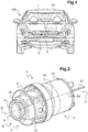
- the figure 1 shows a motor vehicle 100 equipped with at least one driving assistance system 1 according to the invention.
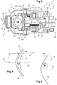
- the driving assistance system 1 comprises in particular at least one optical sensor 13 and a protection device 3 of the optical sensor 13 represented on the figures 2 and 3 .
- the optical sensor 13 is for example an optical sensor 13 for shooting such as a camera. It may be a CCD ("coupled coupled device") or a CMOS sensor comprising a matrix of miniature photodiodes. According to another variant, it may be a sensor for remote sensing laser called LIDAR sensor, acronym in English of "light detection and ranging”.
- CCD coupled coupled device
- CMOS complementary metal-oxide-semiconductor
- LIDAR sensor acronym in English of "light detection and ranging”.
- the optical sensor 13 has an optic 14 optical axis 15.
- the optics 14 is for example an objective.
- An objective may comprise at least one lens, in particular several lenses depending on the field of vision and the resolution, for example between two and ten lenses, generally four or five lenses, even ten lenses in the case of a so-called fish-eye optics ("fish-eye" in English).
- At least one of the lenses of the optics 14 is for example convex (convex) convexity facing outwardly of the optical sensor 13, such as a so-called fish-eye optics ("fish-eye" in English).
- the optical sensor 13 may further comprise a support portion 17 ( figure 3 ) of the optical sensor 13. This is a rear portion of the optical sensor 13 on the side opposite the optic 14.
- the optical sensor 13 is intended to be mounted in the protection device 3. More precisely, the optical sensor 13 and in particular its support 17 are intended to be fixedly mounted in the protection device 3.
- the protective device 3 is mounted at the front of the vehicle 100 at a bumper.
- the protection device 3 can be mounted at the rear of the vehicle 100, for example at the bumper or the license plate. It can also for example be mounted on the sides of the vehicle, for example at the mirrors.
- the protective device 3 can be fixed according to any known technique, on any element 2 of the vehicle 100, such as a bodywork element or an external element such as a bumper, a rearview mirror or a license plate.
- a bodywork element such as a bumper, a rearview mirror or a license plate.
- an external element such as a bumper, a rearview mirror or a license plate.
- a clip system such as a clip, a screwing system, or a bonding system.
- the protective device 3 is therefore a motorized device.
- the protection device 3 may comprise a first subassembly B and a second subset C which are distinct and assembled to one another.
- the first subassembly B may form the accessory 4 for a motor vehicle 100.
- the second subassembly C may comprise the engine 5, to drive in rotation the first subset B.
- the accessory 4 or means of protection may be at least partially transparent.
- the accessory 4 comprises an optical element 9.
- the accessory 4, and more generally the protection device 3 also advantageously comprises a housing 6 secured to the optical element 9.
- the optical element 9 can be made in one piece with the housing 6. Alternatively, the housing 6 and the optical element 9 can be made by two separate parts secured.
- optical element 9 and the housing 6 are described in more detail below.
- the optical element 9, better visible on the Figures 2 to 4 is intended to protect the optics 14 of the optical sensor 13 possible projections of dirt or solid debris that could damage this optic 14. It is therefore a protective element, or more precisely a protective mask of the optical sensor 13, and it is this optical element 9 which is subjected to external aggression, that is to say both projections of water, pollutants, gravel pollutants or deposits of pollutants. traces of water.
- the optical element 9 is distinct from the optical sensor 13.
- This optical element 9 has an optical axis 91.
- the optical element 9 is arranged upstream of the protection device 3.
- the optical element 9 is arranged at the front of the protection device 3.
- the optical element 9 is arranged at the front of the accessory 4, or at the front of the housing 6.
- the front of the protection device 3 is the part intended to cope with to the road scene whose optical sensor 13 participates in the shooting, when the protection device 3 is mounted on the vehicle 100 ( figure 1 ).
- the back of the protection device 3 is the opposite side to the front; it is therefore the furthest part of the road scene whose optical sensor 13 participates in the shooting.
- the optical element 9 is intended to be disposed upstream of the optical sensor 13, more precisely upstream of the optic 14.
- the term "upstream” is defined with respect to the optical axis 15 and relative to to the road scene whose optical sensor 13 participates in the shooting.
- upstream it is understood by "upstream” of the optic 14, a position in which the optical element 9 is disposed between the optics 14 and the road scene whose optical sensor 13 participates in the shooting, according to the optical axis 15.
- This optical element 9 is advantageously sized so as to cover the entire surface of the optic 14.
- the optical element 9 is advantageously transparent so as not to impair the efficiency of the optical sensor 13.
- This optical element 9 may be made of glass or a transparent plastic material such as polycarbonate.
- the optical element 9 can be arranged centrally with respect to the optical sensor 13, more precisely centrally with respect to the optic 14.
- the optical element 9 is arranged so that its optical axis 91 coincides with the optical axis 15 of the optical sensor 13 (see figure 4 ).
- the optical element 9 has at least one surface 9a, 9b of generally aspheric shape. More specifically, the portion of the optical element 9 intended to be arranged directly facing the optic 14 has this or these surfaces 9a, 9b of generally aspheric shape.
- aspheric optical element 9 does not marry the shape of a sphere.
- the curvature of such an aspherical surface 9a, 9b is not constant at all points, unlike that of a sphere.
- the optical element 9 therefore does not have a simple spherical shape but is of more complex shape.
- the optical element here is of aspherical shape, that is to say with a shape that is close to a spherical shape, and that this aspherical shape must be considered for a given thickness of the element.
- optical defined between a profile defining the inner surface of the optical element and a profile defining the outer surface of this optical element. It is the general profiles of the external and / or internal surfaces that must be taken into consideration and the presence of bead and / or spikes on the outer surface, in particular of the optical element, must not be taken into account here for the definition. of the aspherical form of the optical element.
- the parameter c corresponds to the curvature of the surface of the optical element 9.
- This parameter c is the inverse of the radius of curvature R (see figure 5 ).
- the radius of curvature R varies with the distance to the optical axis 91.
- the radius of curvature R can be defined as that of the circle tangent to the surface at the point considered.
- Such a circle is called an osculating circle.
- Such a circle is represented schematically by a line with dashes on the figure 5 .
- the radius of curvature R is between 5mm and 15mm.
- the curvature c is therefore between 1 15 mm -1 and 1 5 mm -1 .
- the parameter r corresponds to the radial distance to the optical axis 91, as shown schematically in FIG. figure 4 .
- the parameter k corresponds to the conical constant, also called taper constant. It is a mathematical value representative of the variation of the curvature of the surface between its central part and its edges. In other words, the parameter k characterizes the variation of the radius of curvature R as one moves away from the vertex. This variation confers particular optical properties on the surfaces that possess this property of asphelity.
- the parameters ⁇ i [1, .., 4] correspond to the aspheric coefficients.
- the polynomial terms ⁇ 1 r 2 to ⁇ 4 r 8 go up to a power 8 of the radial distance r , but of course there may be less of these polynomial terms or on the contrary, more.
- ⁇ 1 is between 0.01 and 0.1; ⁇ 2 between -10 -5 and -10 -6 ; ⁇ 3 between 10 -9 and 10 -10 and ⁇ 4 between 10 -10 and 10 -11 .
- the aspheric surface forms a conical section.
- equation (b) the parameters c, k, r are the same as in equation (a). In other words, equation (b) corresponds to equation (a) with coefficients ⁇ i zero.
- the aspherical surface 9a, 9b can have different conical shapes, such as elliptical, parabolic or even hyperbolic.
- At least one surface 9a, 9b of the optical element 9 is of generally hyperbolic form.
- the arrow z of the surface 9a, 9b of general hyperbola form is given by equation (b).
- the conical constant k is less than -1, in particular much smaller than -1.
- the conical constant k is less than -50, in particular the conical constant k is between -50 and -200.
- the optical element 9 has an inner surface 9a and an outer surface 9a opposite.
- the inner surface 9a and the outer surface 9b each have a general aspherical shape, and in particular a general shape of hyperbola.
- the aspherical, or more precisely hyperbolic, shapes are different between the inner surface 9a and the outer surface 9b of the optical element 9.
- it is the general profile of the inner surface and the outer surface that must be taken in consideration for evaluating the aspherical shape, and in particular the shape of hyperbola, without taking into account the roughness of this surface and the presence of beads or pins modeling the surface state.
- the conical constant k is different for the inner surface 9a and the outer surface 9b.
- the aspherical coefficients ⁇ i are different in the equation (a) of the arrow z of the inner surface 9a and in that of the arrow z of the outer surface 9b.
- the inner 9a and outer 9b surfaces may be parallel, that is to say that for these two surfaces 9a and 9b, one can have the same conical constant k and the same coefficients ⁇ i in the equation (a) of the arrow z .
- the surface 9a, respectively 9b, aspherical of the optical element 9 may be convex or concave.
- the optical element 9 is of generally convex shape. According to the illustrated example, it is the portion of the optical element 9 intended to be arranged in the field of view of the optical sensor 13, which has this substantially convex shape.
- the aspherical surfaces 9a, 9b of the optical element 9 are convex with their outwardly oriented convexities of the protection device 3.
- the optical element 9 can be arranged at a distance d from the optic 14 (see figure 4 ) which is less than 5mm, or less than 3mm of the optic 14, for example of the order of 2mm.
- the optical element 9 can therefore be arranged very close to the optics 14 while maintaining a large viewing angle, especially greater than 110 °, for example of the order of 190 °, and good optical performance due to the surfaces. 9a, 9b aspherical.
- the aspherical surfaces 9a, 9b offer a better optical performance with respect to an optical element that would be made with constant spherical surfaces.
- the overall hyperbolic shape of the inner 9a and outer 9b surfaces of the optical element 9 is particularly advantageous for such a small distance d between the optic 14 and the optical element 9.
- the optical element 9 may have a very small thickness, for example of the order of a millimeter.
- optical element 9 is mounted to rotate about an axis of rotation A1, schematized on the figures 2 and 3 .
- the axis of rotation A1 of the optical element 9 coincides with the optical axis 15 of the optical sensor 13.
- This axis of rotation A1 is also coincident with the optical axis 91 of the optical element 9.
- the optical element 9 may be arranged centrally with respect to the axis of rotation A1. This optical element 9 has in particular a symmetry of revolution with respect to the axis of rotation A1.
- optics 14 and the element 9 advantageously protrude from an opening provided on the element 2 of the vehicle 100.
- the optical sensor 13 has a large viewing angle and the optic 14 remains clean due to the presence of the element 9 between the optics 14 and the outside of the vehicle 100 ( figure 1 ).
- the inner surface 9a of the optical element 9 advantageously has an anti-fogging property.
- the inner surface 9a of the optical element 9 is the surface intended to be arranged opposite the optics 14 of the optical sensor 13.
- the inner surface 9a of the optical element 9 has an anti-fog coating.
- the inner surface 9a and / or outer 9b of the optical element 9 may have one or more of the following properties: hydrophobic, infra-red filter, photocatalytic, super hydrophobic, lipophobic, hydrophilic, or super hydrophilic , chipping resistance, or any other surface treatment to reduce the adhesion of dirt.
- hydrophobic, infra-red filter photocatalytic, super hydrophobic, lipophobic, hydrophilic, or super hydrophilic , chipping resistance, or any other surface treatment to reduce the adhesion of dirt.
- any drops of water will run on the outer surface without leaving any traces because the water will not adhere to this external surface.
- a liquid solution such as a Rain-X® solution, may be deposited on the outer surface 9b of the optical element 9 to form a hydrophobic film.
- the optical element 9 of the protection device 3 may also comprise an integrated defrosting or defogging system in order to guarantee good operability of the driver assistance system 1 whatever the weather conditions, such as a filament or a defrosting resistor for example.
- the housing 6 it is rotatably mounted about the axis of rotation A1.
- the housing 6 is a waterproof housing.
- the housing 6 may be made of any suitable material known to those skilled in the art.
- this housing 6 is arranged to be rotated by the motor 5, which allows the rotation of the optical element 9.
- the optical element 9 is in this particular example, configured to be rotated with the housing 6, so as to allow cleaning of the optical element 9 by centrifugal effect.
- the optical element 9 is configured to be disposed at the front of the housing 6.
- the front of the housing 6 is the part of the housing 6 intended to face the road scene whose optical sensor 13 participates in the when the protective device 3 is mounted on the vehicle 100 (also referring to the figure 1 ).
- the rear of the housing 6 is the portion of the housing 6 opposite the front of the housing 6 and is the furthest part of the road scene whose optical sensor 13 participates in the shooting .
- the optical sensor 13 is in this example mounted at least partly in the housing 6.
- the housing 6 comprises a housing 19 (see figure 3 ) configured to receive the optical sensor 13, for example so that the optical axis 15 of the optical sensor 13, coincides with the axis of rotation A1 of the housing 6.
- the housing 6 comprises a wall 21 defining the housing 19 for the optical sensor 13.
- This wall 21 may be centered around the axis of rotation A1 of the optical element 9 and the housing 6.
- the wall 21 is of generally cylindrical general shape.
- the wall 21 can be made in one piece with the optical element 9.
- the wall 21 and the optical element 9 can be made by two separate parts, and in this case the wall 21 is secured at one end to the optical element 9. This is in particular the front end of the wall 21 which is secured to the optical element 9.
- the connection between the wall 21 and the optical element 9 can be done by ultrasonic welding.
- the housing 6 and the optical element 9 can be made in one or more rooms. The housing 6 being secured to the optical element 9, this forms a block sealing thus preventing the introduction of dirt inside the housing 6 for receiving the optical sensor 13.
- anti-condensation means advantageously at least one means for limiting condensation, hereinafter referred to as anti-condensation means.
- anti-condensation means can be provided at the housing 6.
- at least one anti-condensation means can be arranged on the wall 21 of the housing 6.
- the anti-condensation means may comprise at least one orifice 210 passing through the housing 6, in this example on the wall 21 (see FIG. figure 3 ).
- the orifices 210 may be made by drilling.
- they are arranged symmetrically with respect to the axis of rotation A1 of the housing 6.
- each orifice 210 may have a diameter of the order of 5 mm.
- one or more semi-permeable membranes 211 may be provided, respectively arranged at least at an orifice 210. According to the example illustrated in FIG. figure 3 two membranes 211 are shown schematically. Each membrane 211 may be attached to a port 210 associated sealingly, for example by gluing or by ultrasonic welding. These membranes 211 are, according to the described embodiments, permeable to air and impermeable to water. The membrane or membranes 211 thus promote the flow of air inside the housing 6. This allows good ventilation between the optical 14 and the optical element 9 and thus prevents the accumulation of condensation.
- the two membranes 211 are placed symmetrically with respect to the axis of rotation A1 of the housing 6 and it is this symmetrical arrangement which makes it possible to limit the effects of mass with respect to the centrifugal force during the rotation of the housing 6 .
- small electric motor is meant in the context of the present invention a stepper motor, an actuator, a DC motor with or without a brush, an asynchronous motor or a synchronous motor, whose mass is less than 10 kg, even less than 1kg, in particular used to operate equipment for vehicles.
- miniature electric motor is meant in the context of the present invention a stepper motor, an actuator, a DC motor with or without brushes, an asynchronous motor or a synchronous motor, whose mass is less than 200g or less at 100 g, preferably between 30 g and 100 g, for example between 30 g and 60 g.
- the motor 5 comprises a rotor 51 and a fixed stator 53, the rotor 51 being able to rotate with respect to the fixed stator 53.
- the motor 5 is coupled to the housing 6 to rotate the housing 6 and the optical element 9. According to the embodiment described, the housing 6 and the optical element 9 are integral with the rotor 51 of the motor 5.
- the rotor 51 is disposed around the stator 53.
- the stator 53 is therefore inside and the rotor 51 outside.
- the stator 53 can form the support 17 of the optical sensor 13. In other words, the support 17 and the stator 53 are made in one piece.
- stator 53 can be arranged around the rotor 51.
- the motor 5 is arranged at the rear of the protection device 3, more precisely the motor 5 is assembled at the rear of the housing 6. In other words, the motor 5 is arranged on the opposite side to the optical element 9.
- a sealed block is thus formed, thus preventing the introduction of dirt inside the housing 6 intended to receive the optical sensor 13.
- the motor 5 is in this example arranged in the extension of the optical sensor 13.
- the motor 5 is advantageously a hollow motor. He can receive at least part the optical sensor 13.
- the stator 53 can receive at least part of the support 17 of the optical sensor 13.
- the hollow rotor 51 can receive at least part of the stator 53 forming a support 17 of the optical sensor 13.
- the motor 5 is for example electrically powered by a power supply connected to the general electrical circuit of the vehicle 100 (also referring to the figure 1 ).
- the motor 5 may be more particularly a brushless motor, also known under the name "brushless motor” in English.
- the motor 5 comprises at least one magnet 55 integral with the rotor 51, and a predefined number of electromagnetic coils 57, in particular at least three electromagnetic coils 57 mounted on the stator 53.
- the electromagnetic coils 57 are intended to be powered to enable the electromagnetic coils 57 to drive of the magnet 55 secured to the rotor 51.
- the motor 5 comprises for this purpose a control circuit 59 for the supply of the electromagnetic coils 57.
- This control circuit 59 can be connected to a connected power supply harness 61 to the general electrical circuit of the vehicle 100 (also referring to figure 1 ).
- the motor 5 can have a rotation speed of between 1000 and 50000 revolutions / minute, preferably between 5000 and 20000 revolutions / minute, and more preferably between 7000 and 15000 revolutions / minute. Such rotational speeds allow the removal of any soil that would have deposited on the optical element 9 by centrifugal effect and thus maintain the optics 14 of the optical sensor 13 clean to ensure optimized operation of the assistance system to driving 1.
- the motor 5 is configured to rotate the accessory 4, namely in this example the housing 6 and the optical element 9 integral with the housing 6.
- the motor 5 is rotatably mounted about an axis of rotation A2.
- the motor 5 is for example arranged so that its axis of rotation A2 coincides with the axis of rotation A1 of the optical element 9, and with the optical axis 15 of the optical sensor 13.
- the protective device 3 thus comprises a movable part 31, also called a rotating part 31, and a fixed part 33 (see figure 3 ).
- the movable part 31 comprises at least the rotor 51 of the motor 5, and the fixed part 33 comprises at least the stator 53 of the motor 5.
- the movable portion 31 of the motorized device 3 may also comprise at least one movable element integral with the rotor 51, such as in particular the accessory 4, that is to say the housing 6 and the optical element 9 in this example.
- the fixed portion 33 may also comprise an element or support fixed to the stator 53.
- the element or support may be fixed directly or not to the stator 53.
- the fixed part 33 the motorized device 3 comprises the fixed support 17 of the optical sensor 13. This fixed support 17 is in particular fixed to the stator 53.
- the support 17 of the optical sensor 13 and the stator 53 advantageously have respective complementary openings 63, 65 to enable the control circuit 59 to be connected to the power supply harness 61.
- the protection device 3 may comprise in particular one or more bearings 27, 28 represented schematically on the figure 3 .
- the protection device 3 comprises two bearings 27, 28.
- bearings 27, 28 are each arranged between the movable portion 31 and the fixed portion 33 of the protection device 3.
- the bearings 27, 28 are generally substantially annular.
- the two bearings 27, 28 are arranged concentrically with the motor 5.
- one of the bearings for example the bearing 27 may be disposed between the rotor 51 and a portion, in particular a front portion, of the support 17 of the optical sensor 13.
- the other bearing, the bearing 28 in the example of the figure 3 is disposed between the rotor 51 and the stator 53 of the motor 5.
- the two bearings 27 and 28 can be arranged between the rotor 51 and the stator 53.
- the two bearings 27, 28 are arranged between the rotor 51 and the stator 53 forming a support 17 of the optical sensor 13.
- At least one of these bearings 27, 28 may be a magnetic bearing.
- Such a magnetic bearing avoids the noise and friction generally caused during operation of the protective device 3 using mechanical bearings.
- a bearing may be magnetic and the other bearing may be a mechanical bearing such as a ball bearing.
- the motorized device 3 may comprise a single magnetic bearing.
- this optical element 9 in particular via the housing 6, ensures that the field of view of the optical sensor 13 is always clear and clean.
- the rotation of the optical element 9 ensures the removal of dirt due to the centrifugal force that they undergo.
Landscapes
- Physics & Mathematics (AREA)
- Engineering & Computer Science (AREA)
- General Physics & Mathematics (AREA)
- Mechanical Engineering (AREA)
- Optics & Photonics (AREA)
- Spectroscopy & Molecular Physics (AREA)
- Computer Networks & Wireless Communication (AREA)
- Radar, Positioning & Navigation (AREA)
- Remote Sensing (AREA)
- Signal Processing (AREA)
- Multimedia (AREA)
- Electromagnetism (AREA)
- Studio Devices (AREA)
- Lens Barrels (AREA)
- Blocking Light For Cameras (AREA)
- Camera Bodies And Camera Details Or Accessories (AREA)
- Surface Treatment Of Optical Elements (AREA)
Abstract
L'invention concerne un dispositif de protection (3) d'un capteur optique (13) pour véhicule automobile, ledit capteur optique (13) comprenant une optique (14).The invention relates to a protection device (3) for an optical sensor (13) for a motor vehicle, said optical sensor (13) comprising an optic (14).
Selon l'invention, le dispositif de protection (3) comporte un élément optique (9) configuré pour être disposé en amont de l'optique (14) du capteur optique (13) et présentant au moins une surface (9a, 9b) de forme générale asphérique.According to the invention, the protection device (3) comprises an optical element (9) configured to be arranged upstream of the optics (14) of the optical sensor (13) and having at least one surface (9a, 9b) of general aspheric form.
L'invention concerne également un système d'assistance à la conduite correspondant.

Description
La présente invention se rapporte au domaine de l'aide à la conduite et notamment aux systèmes d'assistance à la conduite, implantés sur certains véhicules, le système d'assistance à la conduite pouvant comporter un capteur optique, comme par exemple une caméra comprenant un objectif, notamment comprenant au moins une lentille. Plus particulièrement, l'invention concerne un dispositif de protection d'un tel capteur optique.The present invention relates to the field of driving assistance and especially to driver assistance systems, installed on certain vehicles, the driving assistance system may include an optical sensor, such as a camera comprising an objective, in particular comprising at least one lens. More particularly, the invention relates to a device for protecting such an optical sensor.
Actuellement, des caméras de vision avant, arrière, ou encore latérales équipent un grand nombre de véhicules automobiles. Elles font notamment partie de systèmes d'assistance à la conduite, tels que des systèmes d'aide au stationnement, ou encore des systèmes de détection de franchissement de ligne.Currently, front, rear or side vision cameras equip a large number of motor vehicles. They are notably part of driver assistance systems, such as parking assistance systems, or line crossing detection systems.
On connait des caméras qui sont installées à l'intérieur de l'habitacle d'un véhicule contre la lunette / vitre arrière en visant vers l'arrière depuis la lunette arrière du véhicule. Ces caméras sont bien protégées des aléas climatiques extérieurs et des salissures causées par des polluants organiques ou minéraux. Cependant, l'angle de vue pour de telles caméras, installées à l'intérieur de l'habitacle, n'est pas optimal, en particulier pour une aide au stationnement, car elles ne permettent pas de voir les obstacles se trouvant à proximité de l'arrière du véhicule par exemple.Cameras are known that are installed inside the cabin of a vehicle against the rear window / window looking towards the rear from the rear window of the vehicle. These cameras are well protected from external climatic hazards and dirt caused by organic pollutants or minerals. However, the angle of view for such cameras, installed inside the cabin, is not optimal, especially for a parking aid, because they do not allow to see the obstacles in the vicinity of the rear of the vehicle for example.
Pour cette raison, on préfère donc installer les caméras des systèmes d'assistance à la conduite à l'extérieur des véhicules à différents endroits selon l'utilisation souhaitée, par exemple au niveau du pare-chocs arrière ou avant, ou au niveau de la plaque d'immatriculation arrière ou avant du véhicule. Dans ce cas, la caméra est donc fortement exposée aux projections de saletés minérales ou organiques qui peuvent se déposer sur son optique et ainsi réduire son efficacité, voire la rendre inopérante. En particulier par temps de pluie, on constate des projections de pluie et de saletés qui peuvent grandement affecter l'opérabilité du système d'assistance à la conduite comprenant une telle caméra. Les surfaces des optiques des caméras doivent être nettoyées afin de garantir leur bon état de fonctionnement.For this reason, it is therefore preferred to install the cameras of the driver assistance systems outside the vehicles in different places according to the desired use, for example at the rear or front bumper, or at the level of the vehicle. rear registration plate or front of the vehicle. In this case, the camera is highly exposed to the projections of mineral or organic dirt that can be deposited on its optics and thus reduce its effectiveness, or even make it inoperative. Especially in rainy weather, there are projections of rain and dirt that can greatly affect the operability of the driver assistance system comprising such a camera. The surfaces of the optics of the cameras must be cleaned to ensure that they are in good working order.
Pour contrer le dépôt de saletés sur la caméra, il est connu d'agencer un dispositif de nettoyage de l'optique de la caméra, généralement un gicleur de liquide de nettoyage, à proximité de celle-ci, pour supprimer les éléments polluants qui se sont déposés au cours du temps. Cependant, l'utilisation de ces gicleurs entraine une augmentation des couts de fonctionnement d'un tel système d'assistance à la conduite car ils nécessitent l'utilisation de quantités de liquide de nettoyage assez importantes.To counteract the deposition of dirt on the camera, it is known to arrange a device for cleaning the optics of the camera, usually a nozzle of cleaning fluid, close to it, to remove the polluting elements that are filed during time. However, the use of these nozzles leads to an increase in operating costs of such a driving assistance system because they require the use of quantities of cleaning liquid quite important.
Selon une solution connue, des moyens de vibration d'une vitre de protection de la caméra sont prévus afin d'en décoller les saletés de la vitre de protection de la caméra. Toutefois, il a été constaté que l'efficacité d'un tel dispositif pour des salissures tenaces et incrustées peut être limitée malgré la vibration de la vitre de protection.According to a known solution, means for vibrating a protective window of the camera are provided in order to remove the dirt from the protective window of the camera. However, it has been found that the effectiveness of such a device for stubborn and encrusted dirt can be limited despite the vibration of the protective glass.
Selon une autre solution, la caméra est agencée dans un dispositif de protection. Cependant, un tel dispositif de protection est très encombrant à installer.According to another solution, the camera is arranged in a protective device. However, such a protective device is very bulky to install.
De plus, l'utilisation d'un tel dispositif de protection ne permet pas toujours d'avoir un grand angle de vision.In addition, the use of such a protective device does not always make it possible to have a large viewing angle.
La présente invention se propose de remédier au moins partiellement aux inconvénients ci-dessus mentionnés en présentant une alternative d'un dispositif de protection d'un capteur optique permettant d'empêcher le dépôt de salissures sur le capteur optique tel qu'une caméra tout en conservant un grand angle de vision.The present invention proposes to remedy at least partially the disadvantages mentioned above by presenting an alternative of a protective device of an optical sensor for preventing the deposition of dirt on the optical sensor such as a camera while maintaining a large viewing angle.
À cet effet l'invention a pour objet un dispositif de protection d'un capteur optique pour véhicule automobile, ledit capteur optique comprenant une optique, caractérisé en ce que le dispositif de protection comporte un élément optique configuré pour être disposé en amont de l'optique du capteur optique et présentant au moins une surface de forme générale asphérique.To this end, the subject of the invention is a device for protecting an optical sensor for a motor vehicle, said optical sensor comprising an optical element, characterized in that the protection device comprises an optical element configured to be disposed upstream of the optical sensor. optical optical sensor and having at least one surface of generally aspherical shape.
La ou les formes asphériques permettent d'obtenir un dispositif de protection compact sans trop dévier les rayons, et donc sans trop altérer les performances optiques du capteur optique qui serait placé derrière un tel élément optique.The one or more aspherical shapes make it possible to obtain a compact protection device without unduly deflecting the rays, and thus without greatly affecting the optical performance of the optical sensor that would be placed behind such an optical element.
On comprend que la ou les formes asphériques sont définies pour chaque surface en regard de son profil général, indépendamment de l'état de surface et de la rugosité de cette surface. A titre d'exemple, si un ou plusieurs bourrelets sont réalisés en surface de l'élément optique pour l'obtention d'un effet optique, par exemple diffusant, ou pour éviter la stagnation de liquide en surface, ces bourrelets ne sont pas considérés comme participant à définir la forme générale de l'élément optique et donc ne sont pas considérés pour évaluer le caractère asphérique de celle-ci.It is understood that the one or more aspherical shapes are defined for each surface with respect to its overall profile, independently of the surface state and the roughness of this surface. For example, if one or more beads are made on the surface of the optical element to obtain an optical effect, for example diffusing, or to avoid stagnation of liquid surface, these beads are not considered as a participant in defining the general shape of the optical element and therefore are not considered to evaluate the aspheric nature of it.
Ledit dispositif de protection du capteur optique peut en outre comporter une ou plusieurs caractéristiques suivantes, prises séparément ou en combinaison :
- l'élément optique est au moins partiellement transparent ;
- ladite au moins une surface est une surface hyperbolique ;
- la flèche de ladite au moins une surface de l'élément optique en fonction de la distance radiale à l'axe optique de l'élément optique est donnée par l'équation (a) :

- c correspond à la courbure de la surface de l'élément optique,
- r à la distance radiale à l'axe optique,
- k à la constante conique, et
- αi[1,..,4] aux coefficients asphériques.
- la constante conique est inférieure à -1, de préférence inférieure à -50 ;
- la constante conique est comprise entre -50 et -200 ;
- la courbure de ladite au moins une surface de l'élément optique est comprise entre


- l'élément optique présente une surface interne et une surface externe opposées, telles que la surface interne et la surface externe sont de formes générales asphériques différentes ;
- la surface interne et la surface externe vérifient l'équation (a) ;
- la constante conique est différente entre les équations (a) de la flèche de la surface interne et de la surface externe de l'élément optique ;
- les coefficients asphériques sont différents entre les équations (a) de la flèche de la surface interne et de la surface externe de l'élément optique ;
- l'élément optique est configuré pour être agencé à une distance inférieure à 5mm de l'optique du capteur optique, de préférence inférieure à 3mm de l'optique du capteur optique ;
- l'élément optique est configuré pour être disposé en amont de l'optique du capteur optique de sorte que l'axe optique de l'élément optique soit confondu avec l'axe optique du capteur optique ;
- l'élément optique est monté mobile en rotation autour d'un axe de rotation ;
- l'élément optique est disposé de façon centrée par rapport à son axe de rotation ;
- l'élément optique est agencé en amont du dispositif de protection de façon à faire face à une scène de route dont le capteur optique est configuré pour participer à la prise de vues ;
- ledit dispositif comporte un boitier solidarisé avec l'élément optique et présentant un logement configuré pour recevoir le capteur optique ;
- la surface interne présente une propriété antibuée, en particulier la surface interne dudit élément optique présente un revêtement antibuée ;
- la surface interne et/ou la surface externe présente au moins une propriété choisie dans la liste suivante : filtre infra-rouge, photocatalytique, hydrophobe, super hydrophobe, lipophobe, hydrophile, super hydrophile, résistance aux gravillons.
- the optical element is at least partially transparent;
- said at least one surface is a hyperbolic surface;
- the arrow of said at least one surface of the optical element as a function of the radial distance to the optical axis of the optical element is given by equation (a):
- c corresponds to the curvature of the surface of the optical element,
- r at the radial distance to the optical axis,
- k at the conical constant, and
- α i [1, .., 4] to the aspherical coefficients.
- the conical constant is less than -1, preferably less than -50;
- the conical constant is between -50 and -200;
- the curvature of said at least one surface of the optical element is between
- the optical element has an opposite inner surface and an outer surface, such that the inner surface and the outer surface are of different general aspherical shapes;
- the inner surface and the outer surface satisfy equation (a);
- the conical constant is different between the equations (a) of the arrow of the inner surface and the outer surface of the optical element;
- the aspherical coefficients are different between the equations (a) of the arrow of the inner surface and the outer surface of the optical element;
- the optical element is configured to be arranged at a distance less than 5mm from the optics of the optical sensor, preferably less than 3mm from the optics of the optical sensor;
- the optical element is configured to be disposed upstream of the optics of the optical sensor so that the optical axis of the optical element coincides with the optical axis of the optical sensor;
- the optical element is rotatably mounted about an axis of rotation;
- the optical element is disposed centrally with respect to its axis of rotation;
- the optical element is arranged upstream of the protection device so as to face a road scene whose optical sensor is configured to take part in the shooting;
- said device comprises a housing secured to the optical element and having a housing configured to receive the optical sensor;
- the inner surface has an anti-fogging property, in particular the inner surface of said optical element has an anti-fog coating;
- the inner surface and / or the outer surface has at least one property chosen from the following list: infra-red, photocatalytic, hydrophobic, super hydrophobic, lipophobic, hydrophilic, super-hydrophilic, gravel-resistant.
L'invention concerne également un système d'assistance à la conduite comportant un capteur optique comprenant une optique. Selon l'invention, ledit système comporte un dispositif de protection du capteur optique tel que défini précédemment.The invention also relates to a driving assistance system comprising an optical sensor comprising an optical element. According to the invention, said system comprises a device for protecting the optical sensor as defined above.
Selon un aspect de l'invention, l'élément optique est distinct du capteur optique.According to one aspect of the invention, the optical element is distinct from the optical sensor.
D'autres caractéristiques et avantages de l'invention apparaitront plus clairement à la lecture de la description suivante, donnée à titre d'exemple illustratif et non limitatif, et des dessins annexés parmi lesquels :
- la
figure 1 représente de façon schématique un véhicule automobile comprenant un système d'assistance à la conduite selon l'invention, - la
figure 2 est une vue en perspective d'un dispositif de protection d'un capteur optique du système d'assistance de lafigure 1 , - la
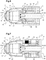
figure 3 est une vue en coupe longitudinale partielle du dispositif de protection de lafigure 2 , - la
figure 4 est une vue représentant de manière partielle et schématique un capteur optique du système d'assistance à la conduite et un élément optique de protection du capteur optique, - la
figure 5 représente de façon schématique une surface de forme générale asphérique de l'élément optique, - la
figure 6 est une variante du dispositif de protection, et - la
figure 7 est une autre variante du dispositif de protection.
- the
figure 1 schematically represents a motor vehicle comprising a driving assistance system according to the invention, - the
figure 2 is a perspective view of a device for protecting an optical sensor of the assistance system of thefigure 1 , - the
figure 3 is a partial longitudinal sectional view of the protective device of thefigure 2 , - the
figure 4 is a view partially and schematically showing an optical sensor of the driver assistance system and an optical element for protecting the optical sensor, - the
figure 5 schematically represents a surface of generally aspherical shape of the optical element, - the
figure 6 is a variant of the protective device, and - the
figure 7 is another variant of the protection device.
Sur ces figures, les éléments identiques portent les mêmes références.In these figures, the identical elements bear the same references.
Les réalisations suivantes sont des exemples. Bien que la description se réfère à un ou plusieurs modes de réalisation, ceci ne signifie pas nécessairement que chaque référence concerne le même mode de réalisation, ou que les caractéristiques s'appliquent à un seul mode de réalisation. De simples caractéristiques de différents modes de réalisation peuvent également être combinées ou interchangées pour fournir d'autres réalisations.The following achievements are examples. Although the description refers to one or more embodiments, this does not necessarily mean that each reference relates to the same embodiment, or that the features apply to a single embodiment. Simple features of different embodiments may also be combined or interchanged to provide other embodiments.
Dans la description, on peut indexer certains éléments, comme par exemple premier élément ou deuxième élément. Dans ce cas, il s'agit d'un simple indexage pour différencier et dénommer des éléments proches mais non identiques. Cette indexation n'implique pas une priorité d'un élément par rapport à un autre et on peut aisément interchanger de telles dénominations sans sortir du cadre de la présente description. Cette indexation n'implique pas non plus un ordre dans le temps.In the description, it is possible to index certain elements, such as for example first element or second element. In this case, it is a simple indexing to differentiate and name close but not identical elements. This indexing does not imply a priority of one element with respect to another and it is easy to interchange such denominations without departing from the scope of the present description. This indexing does not imply an order in time either.
La
Le système d'assistance à la conduite 1 comporte notamment au moins un capteur optique 13 et un dispositif de protection 3 du capteur optique 13 représenté sur les
Le capteur optique 13 (voir
Comme cela est mieux visible sur les
Le capteur optique 13 peut comporter de plus une partie formant support 17 (
Selon le mode de réalisation illustré, le capteur optique 13 est destiné à être monté dans le dispositif de protection 3. Plus précisément, le capteur optique 13 et notamment son support 17 sont destinés à être montés fixes dans le dispositif de protection 3.According to the illustrated embodiment, the
Selon l'exemple illustré sur la
Le dispositif de protection 3 peut être fixé selon toute technique connue, sur tout élément 2 du véhicule 100, tel qu'un élément de carrosserie ou un élément extérieur tel qu'un pare-chocs, un rétroviseur ou une plaque d'immatriculation. À cet effet, on peut citer de façon non exhaustive un système de clips, un système de vissage, ou encore un système de collage.The
Plus précisément, en se référant de nouveau aux
- au moins
un accessoire 4 pour véhicule automobile 100 (en se référant également à lafigure 1 ),cet accessoire 4 étant monté mobile en rotation autour d'un axe de rotation A1 et ayant pour fonction la protection du capteur optique 13, et - un actionneur, plus
précisément un moteur 5, configuré pour entrainer enrotation l'accessoire 4.
- at least one
accessory 4 for a motor vehicle 100 (also referring to thefigure 1 ), thisaccessory 4 being rotatably mounted about an axis of rotation A1 and having the function of protecting theoptical sensor 13, and - an actuator, more precisely a
motor 5, configured to rotate theaccessory 4.
Le dispositif de protection 3 est donc un dispositif motorisé.The
Notamment, le dispositif de protection 3 peut comporter un premier sous-ensemble B et un deuxième sous-ensemble C distincts et assemblés l'un à l'autre. Le premier sous-ensemble B peut former l'accessoire 4 pour véhicule automobile 100. Le deuxième sous-ensemble C peut comporter le moteur 5, pour entrainer en rotation le premier sous-ensemble B.In particular, the
L'accessoire 4 ou moyen de protection peut être au moins partiellement transparent.The
Selon le mode de réalisation décrit, l'accessoire 4 comporte un élément optique 9. Selon ce mode de réalisation, l'accessoire 4, et plus généralement le dispositif de protection 3 comporte également avantageusement un boitier 6 solidarisé à l'élément optique 9.According to the embodiment described, the
L'élément optique 9 peut être réalisé d'une seule pièce avec le boitier 6. En alternative, le boitier 6 et l'élément optique 9 peuvent être réalisés par deux pièces distinctes solidarisées.The
L'élément optique 9 et le boitier 6 sont décrits plus en détail ci-après.The
L'élément optique 9, mieux visible sur les
Selon le mode de réalisation décrit, l'élément optique 9 est distinct du capteur optique 13.According to the embodiment described, the
Cet élément optique 9 présente un axe optique 91.This
L'élément optique 9 est agencé en amont du dispositif de protection 3. Dans cet exemple, l'élément optique 9 est agencé à l'avant du dispositif de protection 3. Autrement dit, l'élément optique 9 est agencé à l'avant de l'accessoire 4, ou encore à l'avant du boitier 6. L'avant du dispositif de protection 3 s'entend de la partie destinée à faire face à la scène de route dont le capteur optique 13 participe à la prise de vues, lorsque le dispositif de protection 3 est monté sur le véhicule 100 (
Plus précisément, l'élément optique 9 est destiné à être disposé en amont du capteur optique 13, plus précisément en amont de l'optique 14. Dans la présente, le terme amont est défini par rapport à l'axe optique 15 et par rapport à la scène de route dont le capteur optique 13 participe à la prise de vues. Autrement dit, on comprend par « en amont » de l'optique 14, une position dans laquelle l'élément optique 9 est disposé entre l'optique 14 et la scène de route dont le capteur optique 13 participe à la prise de vues, selon l'axe optique 15.More precisely, the
Cet élément optique 9 est avantageusement dimensionné de façon à recouvrir toute la surface de l'optique 14.This
Agencé dans le champ de vision du capteur optique 13, l'élément optique 9 est avantageusement transparent afin de ne pas nuire à l'efficacité du capteur optique 13. Cet élément optique 9 peut être réalisé en verre ou en un matériau plastique transparent tel que du polycarbonate.Arranged in the field of view of the
L'élément optique 9 peut être agencé de façon centrée par rapport au capteur optique 13, plus précisément de façon centrée par rapport à l'optique 14. L'élément optique 9 est agencé de sorte que son axe optique 91 est confondu avec l'axe optique 15 du capteur optique 13 (voir
En outre, l'élément optique 9 présente au moins une surface 9a, 9b de forme générale asphérique. Plus précisément, la partie de l'élément optique 9 destinée à être agencée directement en regard de l'optique 14 présente cette ou ces surfaces 9a, 9b de forme générale asphérique.In addition, the
La surface 9a, respectivement 9b, asphérique de l'élément optique 9 n'épouse pas la forme d'une sphère. Autrement dit, la courbure d'une telle surface asphérique 9a, 9b n'est pas constante en tout point, contrairement à celle d'une sphère. L'élément optique 9 ne présente donc pas une simple forme sphérique mais est de forme plus complexe.The
Il convient de noter que l'élément optique est ici de forme asphérique, c'est-à-dire avec une forme qui se rapproche d'une forme sphérique, et que cette forme asphérique doit être considérée pour une épaisseur donnée de l'élément optique définie entre un profil définissant la surface interne de l'élément optique et un profil définissant la surface externe de cet élément optique. Ce sont les profils généraux des surfaces externes et/ou internes qui doivent être pris en considération et la présence de bourrelet et/ou de picots sur la surface externe notamment de l'élément optique ne doit pas être ici pas prise en compte pour la définition de la forme asphérique de l'élément optique.It should be noted that the optical element here is of aspherical shape, that is to say with a shape that is close to a spherical shape, and that this aspherical shape must be considered for a given thickness of the element. optical defined between a profile defining the inner surface of the optical element and a profile defining the outer surface of this optical element. It is the general profiles of the external and / or internal surfaces that must be taken into consideration and the presence of bead and / or spikes on the outer surface, in particular of the optical element, must not be taken into account here for the definition. of the aspherical form of the optical element.
La flèche z de chaque surface asphérique 9a, 9b, en fonction de la distance radiale r à l'axe optique 91 de l'élément optique 9, est donnée par l'équation (a) suivante : ![]()
![]()
Dans cette équation (a), le paramètre c correspond à la courbure de la surface de l'élément optique 9. Ce paramètre c est l'inverse du rayon de courbure R (voir ![]()
![]()
![]()
![]()
De plus, dans l'équation (a), le paramètre r correspond à la distance radiale à l'axe optique 91, comme schématisé sur la
Le paramètre k, non représenté sur les figures, correspond à la constante conique, aussi appelée constante de conicité. Il s'agit d'une valeur mathématique représentative de la variation de la courbure de la surface entre sa partie centrale et ses bords. Autrement dit, le paramètre k caractérise la variation du rayon de courbure R à mesure que l'on s'éloigne du sommet. Cette variation confère des propriétés optiques particulières aux surfaces qui possèdent cette propriété d'asphéricité.The parameter k , not shown in the figures, corresponds to the conical constant, also called taper constant. It is a mathematical value representative of the variation of the curvature of the surface between its central part and its edges. In other words, the parameter k characterizes the variation of the radius of curvature R as one moves away from the vertex. This variation confers particular optical properties on the surfaces that possess this property of asphelity.
Enfin, les paramètres αi[1,..,4] correspondent aux coefficients asphériques. Dans l'équation (a) donnée ci-dessus, les termes polynomiaux α1r2 à α4r8 vont jusqu'à une puissance 8 de la distance radiale r, mais bien entendu il peut y avoir moins de ces termes polynomiaux ou au contraire plus.Finally, the parameters α i [1, .., 4] correspond to the aspheric coefficients. In the equation (a) given above, the polynomial terms α 1 r 2 to α 4 r 8 go up to a power 8 of the radial distance r , but of course there may be less of these polynomial terms or on the contrary, more.
Ces coefficients asphériques αi sont très faibles, notamment inférieurs à 1. À titre d'exemple non limitatif, α1 est compris entre 0,01 et 0,1 ; α2 entre -10-5 et -10-6 ; α3 entre 10-9 et 10-10 et α4 entre 10-10 et 10-11.These aspherical coefficients α i are very small, especially less than 1. By way of non-limiting example, α 1 is between 0.01 and 0.1; α 2 between -10 -5 and -10 -6 ; α 3 between 10 -9 and 10 -10 and α 4 between 10 -10 and 10 -11 .
Selon un exemple particulier, la surface asphérique forme une section conique.In a particular example, the aspheric surface forms a conical section.
Dans ce cas les coefficients asphériques αi sont nuls. La flèche z de l'élément optique 9 en fonction de la distance radiale r à l'axe optique 91 de l'élément optique 9 est alors donnée par l'équation (b) suivante : ![]()
![]()
Dans cette équation (b), les paramètres c, k, r sont les mêmes que dans l'équation (a). En d'autres termes l'équation (b) correspond à l'équation (a) avec les coefficients αi nuls.In this equation (b), the parameters c, k, r are the same as in equation (a). In other words, equation (b) corresponds to equation (a) with coefficients α i zero.
Selon la valeur de la constante conique k, la surface 9a, 9b asphérique peut présenter différentes formes coniques, telles qu'elliptiques, paraboliques ou encore hyperboliques.Depending on the value of the conical constant k , the
Selon un mode de réalisation préféré, au moins une surface 9a, 9b de l'élément optique 9 est de forme générale hyperbolique. La flèche z de la surface 9a, 9b de forme générale d'hyperbole est donnée par l'équation (b). En outre, dans cette équation (b), la constante conique k est inférieure à -1, notamment très inférieure à -1. De préférence, la constante conique k est inférieure à -50, notamment la constante conique k est comprise entre -50 et -200.According to a preferred embodiment, at least one
Par ailleurs, l'élément optique 9 présente une surface interne 9a et une surface externe 9a opposées. La surface interne 9a et la surface externe 9b présentent chacune une forme générale asphérique, et en particulier une forme générale d'hyperbole. Les formes asphériques, ou plus précisément hyperboliques, sont différentes entre la surface interne 9a et la surface externe 9b de l'élément optique 9. Comme précédemment, c'est le profil général de la surface interne et de la surface externe qui doit être pris en considération pour évaluer la forme asphérique, et en particulier la forme d'hyperbole, sans tenir compte de la rugosité de cette surface et de la présence de bourrelets ou picots modelant l'état de surface.Furthermore, the
En particulier, la constante conique k est différente pour la surface interne 9a et pour la surface externe 9b. Selon un exemple de réalisation particulier non limitatif, la constante conique k de l'ordre de -159 pour l'une des surfaces et -76 pour l'autre surface.In particular, the conical constant k is different for the
En outre, les coefficients asphériques αi sont différents dans l'équation (a) de la flèche z de la surface interne 9a et dans celle de la flèche z de la surface externe 9b.In addition, the aspherical coefficients α i are different in the equation (a) of the arrow z of the
Bien entendu, en alternative, les surfaces interne 9a et externe 9b peuvent être parallèles, c'est-à-dire que pour ces deux surfaces 9a et 9b, on peut avoir la même constante conique k et les mêmes coefficients αi dans l'équation (a) de la flèche z.Of course, as an alternative, the inner 9a and outer 9b surfaces may be parallel, that is to say that for these two
Par ailleurs, la surface 9a, respectivement 9b, asphérique de l'élément optique 9 peut être convexe ou concave. Dans cet exemple, l'élément optique 9 est de forme générale convexe. Selon l'exemple illustré, c'est la partie de l'élément optique 9 destinée à être agencée dans le champ de vision du capteur optique 13, qui présente cette forme sensiblement convexe. Ainsi, les surfaces 9a, 9b asphériques de l'élément optique 9 sont convexes avec leurs convexités orientées vers l'extérieur du dispositif de protection 3.Furthermore, the
De plus, l'élément optique 9 peut être agencé à une distance d de l'optique 14 (voir
Enfin, l'élément optique 9 peut présenter une très faible épaisseur, par exemple de l'ordre du millimètre.Finally, the
Par ailleurs, l'élément optique 9 est monté mobile en rotation autour d'un axe de rotation A1, schématisé sur les
Avantageusement, l'axe de rotation A1 de l'élément optique 9 est confondu avec l'axe optique 15 du capteur optique 13. Cet axe de rotation A1 est également confondu avec l'axe optique 91 de l'élément optique 9.Advantageously, the axis of rotation A1 of the
L'élément optique 9 peut être disposé de façon centrée par rapport à l'axe de rotation A1. Cet élément optique 9 présente notamment une symétrie de révolution par rapport à l'axe de rotation A1.The
Par ailleurs, lorsque le dispositif de protection 3 recevant le capteur optique 13 est monté sur le véhicule 100 (en se référant également à la
En outre, afin d'éviter un phénomène de condensation entre l'optique 14 et l'élément optique 9, la surface interne 9a de l'élément optique 9 (voir
En variante ou en complément, la surface interne 9a et/ou externe 9b de l'élément optique 9 peut présenter une ou plusieurs des propriétés suivantes : hydrophobe, filtre infra-rouge, photocatalytique, super hydrophobe, lipophobe, hydrophile, ou encore super hydrophile, résistance aux gravillons, ou encore tout autre traitement de surface permettant de réduire l'adhésion des salissures. En particulier, grâce aux propriétés hydrophobes de la surface externe de l'élément optique 9, des gouttes d'eau éventuelles ruissèleront sur la surface externe sans laisser de traces car l'eau ne pourra pas adhérer sur cette surface externe. Ainsi, les couches ou revêtements sur la surface externe 9b l'élément optique 9, permettent de limiter les possibilités d'adhérence des polluants organiques ou minéraux ainsi que la présence de traces d'eau sur l'élément optique 9 pouvant nuire au bon fonctionnement du système d'assistance à la conduite 1. Avantageusement, une solution liquide, telle qu'une solution de type Rain-X®, peut être déposée sur la surface externe 9b de l'élément optique 9 afin de former une pellicule hydrophobe.Alternatively or in addition, the
Ces exemples de réalisation sont fournis à titre illustratif et non limitatif. Par exemple, l'Homme du métier peut utiliser un élément optique 9 transparent présentant une surface externe 9b ayant d'autres propriétés permettant de limiter l'adhérence des salissures sur cette surface externe 9b sans sortir du cadre de la présente invention.These exemplary embodiments are provided for illustrative and not limiting. For example, a person skilled in the art can use a transparent
De manière optionnelle, l'élément optique 9 du dispositif de protection 3 peut également comprendre un système de dégivrage ou de désembuage intégré pour pouvoir garantir une bonne opérabilité du système d'assistance à la conduite 1 quelles que soient les conditions météorologiques, comme un filament ou une résistance de dégivrage par exemple.Optionally, the
En se référant de nouveau aux
De préférence, le boitier 6 est un boitier étanche. Le boitier 6 peut être réalisé en tout matériau approprié connu de l'homme du métier.Preferably, the
Plus précisément, ce boitier 6 est agencé de façon à être entrainé en rotation par le moteur 5, ce qui permet la rotation de l'élément optique 9. L'élément optique 9 est donc dans cet exemple particulier, configuré pour être entrainé en rotation avec le boitier 6, de façon à permettre un nettoyage de l'élément optique 9 par effet centrifuge.More specifically, this
L'élément optique 9 est configuré pour être disposé à l'avant du boitier 6. L'avant du boitier 6 s'entend de la partie du boitier 6 destinée à faire face à la scène de route dont le capteur optique 13 participe à la prise de vues, lorsque le dispositif de protection 3 est monté sur le véhicule 100 (en se référant également à la
De plus, le capteur optique 13 est dans cet exemple monté au moins en partie dans le boitier 6. Pour ce faire, le boitier 6 comporte un logement 19 (voir
Plus précisément, le boitier 6 comporte une paroi 21 définissant le logement 19 pour le capteur optique 13. Cette paroi 21 peut être centrée autour de l'axe de rotation A1 de l'élément optique 9 et du boitier 6. Dans cet exemple, la paroi 21 est de forme générale sensiblement cylindrique.More specifically, the
Selon une première variante, la paroi 21 peut être réalisée d'une seule pièce avec l'élément optique 9. Selon une deuxième variante, la paroi 21 et l'élément optique 9 peuvent être réalisées par deux pièces distinctes, et dans ce cas la paroi 21 est solidarisée à une extrémité à l'élément optique 9. Il s'agit en particulier de l'extrémité avant de la paroi 21 qui est solidarisée à l'élément optique 9. À titre d'exemple non limitatif, la solidarisation entre la paroi 21 et l'élément optique 9 peut se faire par soudure par ultrasons. Ainsi, le boitier 6 et l'élément optique 9 peuvent être réalisés en une ou plusieurs pièces. Le boitier 6 étant solidaire de l'élément optique 9, cela forme un bloc étanche empêchant ainsi l'introduction de salissures à l'intérieur du boitier 6 destiné à recevoir le capteur optique 13.According to a first variant, the
En variante ou en complément, on prévoit avantageusement au moins un moyen de limitation de la condensation, appelé par la suite moyen anti-condensation. Un tel moyen anti-condensation peut être prévu au niveau du boitier 6. En particulier, au moins un moyen anti-condensation peut être agencé sur la paroi 21 du boitier 6.Alternatively or additionally, advantageously at least one means for limiting condensation, hereinafter referred to as anti-condensation means. Such anti-condensation means can be provided at the
À titre d'exemple non limitatif, le moyen anti-condensation peut comprendre au moins un orifice 210 traversant au niveau du boitier 6, dans cet exemple sur la paroi 21 (voir
Selon l'exemple illustré sur la
De plus, on peut prévoir une ou plusieurs membranes 211 semi-perméables, respectivement agencées au moins au niveau d'un orifice 210. Selon l'exemple illustré sur la
Avantageusement, on prévoit en outre au moins un moyen de compensation de la masse enlevée au niveau de l'orifice 210 ou des orifices 210. Selon l'exemple particulier illustré sur la
En ce qui concerne le moteur 5, dont différentes variantes sont représentées sur les
Par moteur électrique de petite taille on entend dans le cadre de la présente invention un moteur pas à pas, un actuateur, un moteur à courant continu avec ou sans balai, un moteur asynchrone ou un moteur synchrone, dont la masse est inférieure à 10kg, voire inférieure à 1kg, en particulier utilisés pour actionner des équipements pour les véhicules.By small electric motor is meant in the context of the present invention a stepper motor, an actuator, a DC motor with or without a brush, an asynchronous motor or a synchronous motor, whose mass is less than 10 kg, even less than 1kg, in particular used to operate equipment for vehicles.
Par moteur électrique miniature on entend dans le cadre de la présente invention un moteur pas à pas, un actuateur, un moteur à courant continu avec ou sans balais, un moteur asynchrone ou un moteur synchrone, dont la masse est inférieure à 200g, voire inférieure à 100g, de préférence comprise entre 30 g et 100g, par exemple entre 30 g et 60g.By miniature electric motor is meant in the context of the present invention a stepper motor, an actuator, a DC motor with or without brushes, an asynchronous motor or a synchronous motor, whose mass is less than 200g or less at 100 g, preferably between 30 g and 100 g, for example between 30 g and 60 g.
Le moteur 5 comporte un rotor 51 et un stator 53 fixe, le rotor 51 étant mobile en rotation par rapport au stator fixe 53.The
Le moteur 5 est couplé au boitier 6 pour entrainer en rotation le boitier 6 et l'élément optique 9. Selon le mode de réalisation décrit, le boitier 6 et l'élément optique 9 sont solidaires du rotor 51 du moteur 5.The
Selon le mode de réalisation illustré sur les
Alternativement, comme illustré sur la
Par ailleurs, selon les différents modes de réalisation illustrés sur les
On forme ainsi un bloc étanche empêchant ainsi l'introduction de salissures à l'intérieur du boitier 6 destiné à recevoir le capteur optique 13.A sealed block is thus formed, thus preventing the introduction of dirt inside the
En outre, le moteur 5 est dans cet exemple agencé dans le prolongement du capteur optique 13.In addition, the
Le moteur 5 est avantageusement un moteur 5 creux. Il peut recevoir au moins en partie le capteur optique 13.The
Selon la configuration illustrée sur la
Selon la configuration illustrée sur la
Selon la configuration illustrée sur la
Le moteur 5 est par exemple alimenté électriquement par une alimentation reliée au circuit électrique général du véhicule 100 (en se référant également à la
À titre d'exemple non limitatif, le moteur 5 peut être plus particulièrement un moteur sans balais, aussi connu sous la dénomination « brushless motor » en anglais. Selon l'exemple illustré sur la
Le moteur 5 peut avoir une vitesse de rotation comprise entre 1000 et 50000 tours/minute, de préférence entre 5000 et 20000 tours/minute, et de manière encore préférée entre 7000 et 15000 tours/minute. De telles vitesses de rotation permettent l'élimination d'éventuelles salissures qui se seraient déposées sur l'élément optique 9 par effet centrifuge et permettent ainsi de maintenir l'optique 14 du capteur optique 13 propre pour assurer un fonctionnement optimisé du système d'assistance à la conduite 1.The
Le moteur 5 est configuré pour entrainer en rotation l'accessoire 4, à savoir dans cet exemple le boitier 6 et l'élément optique 9 solidaire du boitier 6.The
Le moteur 5 est monté rotatif autour d'un axe de rotation A2. Le moteur 5 est par exemple agencé de sorte que son axe de rotation A2 est confondu avec l'axe de rotation A1 de l'élément optique 9, et avec l'axe optique 15 du capteur optique 13.The
Par ailleurs, on prévoit avantageusement, un agencement étanche à l'arrière du moteur 5 pour le passage des câbles ou fils afin de limiter l'entrée de vapeur d'eau et/ou autres contaminants à l'intérieur du dispositif de protection 3.Furthermore, it is advantageous to provide a sealed arrangement at the rear of the
Le dispositif de protection 3 comporte donc une partie mobile 31, aussi appelée partie tournante 31, et une partie fixe 33 (voir
La partie mobile 31 comprend au moins le rotor 51 du moteur 5, et la partie fixe 33 comprend au moins le stator 53 du moteur 5.The
La partie mobile 31 du dispositif motorisé 3 peut comporter également au moins un élément mobile solidaire du rotor 51, tel que notamment l'accessoire 4, c'est-à-dire le boitier 6 et l'élément optique 9 dans cet exemple.The
De même, la partie fixe 33 peut comprendre également un élément ou support fixé au stator 53. Bien entendu, l'élément ou support peut être fixé directement ou non au stator 53. De façon non limitative, dans cet exemple, la partie fixe 33 du dispositif motorisé 3 comporte le support 17 fixe du capteur optique 13. Ce support fixe 17 est notamment fixé au stator 53.Similarly, the fixed
Le support 17 du capteur optique 13 et le stator 53 comportent avantageusement des ouvertures respectives complémentaires 63, 65 pour permettre le raccordement du circuit de commande 59 au faisceau d'alimentation électrique 61.The
En outre, le dispositif de protection 3 peut comprendre en particulier un ou plusieurs roulements 27, 28 représentés de façon schématique sur la
Ces roulements 27, 28 sont chacun agencés entre la partie mobile 31 et la partie fixe 33 du dispositif de protection 3. Les roulements 27, 28 sont de forme générale sensiblement annulaire. De plus, les deux roulements 27, 28 sont agencés de manière concentrique avec le moteur 5.These
En se référant à l'exemple particulier illustré sur la
En alternative, les deux roulements 27 et 28 peuvent être agencés entre le rotor 51 et le stator 53. Notamment, selon la variante de réalisation illustrée sur la
Par ailleurs, au moins l'un de ces roulements 27, 28 peut être un roulement magnétique. Un tel roulement magnétique permet d'éviter le bruit et les frottements généralement provoqués en fonctionnement du dispositif de protection 3 utilisant des roulements mécaniques.Moreover, at least one of these
Selon une variante, un roulement peut être magnétique et l'autre roulement peut être un roulement mécanique tel qu'un roulement à billes. Selon une autre variante, le dispositif motorisé 3 peut comprendre un unique roulement magnétique.According to one variant, a bearing may be magnetic and the other bearing may be a mechanical bearing such as a ball bearing. According to another variant, the
Ainsi, en agençant à seulement quelques millimètres de l'optique 14 du capteur optique 13, un élément optique 9 avec des surfaces 9a, 9b ayant une telle forme complexe, asphérique voire hyperbolique, on obtient un dispositif de protection 3 compact protégeant de salissures extérieures l'optique 14 du capteur optique 13 tout en garantissant un champ de vision relativement grand, par exemple de l'ordre de 190°.Thus, by arranging only a few millimeters of the optic 14 of the
De plus, la mise en rotation de cet élément optique 9, notamment par l'intermédiaire du boitier 6, assure que le champ de vision du capteur optique 13 soit toujours dégagé et propre. La rotation de l'élément optique 9 assure l'élimination des salissures du fait de la force centrifuge que ces dernières subissent.In addition, the rotation of this
Claims (10)
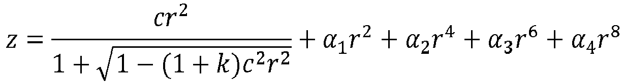
Applications Claiming Priority (1)
| Application Number | Priority Date | Filing Date | Title |
|---|---|---|---|
| FR1754341A FR3066622B1 (en) | 2017-05-17 | 2017-05-17 | OPTICAL SENSOR PROTECTION DEVICE AND ASSOCIATED DRIVING ASSISTANCE SYSTEM |
Publications (1)
| Publication Number | Publication Date |
|---|---|
| EP3404482A1 true EP3404482A1 (en) | 2018-11-21 |
Family
ID=59859168
Family Applications (1)
| Application Number | Title | Priority Date | Filing Date |
|---|---|---|---|
| EP18171905.5A Withdrawn EP3404482A1 (en) | 2017-05-17 | 2018-05-11 | Device for protecting an optical sensor and associated driving-assistance system |
Country Status (6)
| Country | Link |
|---|---|
| US (1) | US20180335505A1 (en) |
| EP (1) | EP3404482A1 (en) |
| JP (1) | JP2019032505A (en) |
| KR (1) | KR20180126399A (en) |
| CN (1) | CN108944712A (en) |
| FR (1) | FR3066622B1 (en) |
Cited By (2)
| Publication number | Priority date | Publication date | Assignee | Title |
|---|---|---|---|---|
| EP4155796A1 (en) * | 2021-09-24 | 2023-03-29 | National Taiwan University | Protective assembly and imaging equipment set |
| US11833978B1 (en) * | 2020-09-24 | 2023-12-05 | Apple Inc. | Sensing system with sensor window having a superhydrophobic surface |
Families Citing this family (6)
| Publication number | Priority date | Publication date | Assignee | Title |
|---|---|---|---|---|
| JP6601576B2 (en) * | 2016-11-30 | 2019-11-06 | 株式会社村田製作所 | Vibration device, water drop removing device for camera, and camera |
| WO2020250510A1 (en) * | 2019-06-10 | 2020-12-17 | 株式会社村田製作所 | Optical device, and optical unit comprising optical device |
| JP7524530B2 (en) | 2019-11-19 | 2024-07-30 | 大日本印刷株式会社 | Infrared Sensor |
| CN111791968A (en) * | 2020-06-09 | 2020-10-20 | 江苏斐飒机械科技有限公司 | Mecanum wheel chassis system |
| CN112373409B (en) * | 2020-10-27 | 2022-07-19 | 北京三快在线科技有限公司 | Camera module and unmanned vehicle |
| WO2023182412A1 (en) * | 2022-03-24 | 2023-09-28 | 大日本印刷株式会社 | Resin panel for infrared sensor, and infrared sensor and article employing said resin panel |
Citations (4)
| Publication number | Priority date | Publication date | Assignee | Title |
|---|---|---|---|---|
| US3879742A (en) * | 1973-10-15 | 1975-04-22 | Triple S Dev Co Inc | Weather-proof enclosure for video camera or the like having centrifugal action window cleaner |
| WO1997022020A1 (en) * | 1995-12-12 | 1997-06-19 | Eugeni Jordana Pareto | Lens structure without spherical aberration and stereoscopic camera including such lens structure |
| KR20070034729A (en) * | 2005-09-26 | 2007-03-29 | 현대자동차주식회사 | Rear camera cleaning device of car |
| US20110181725A1 (en) * | 2010-01-27 | 2011-07-28 | Nippon Soken, Inc. | Optical sensor device for vehicle |
Family Cites Families (5)
| Publication number | Priority date | Publication date | Assignee | Title |
|---|---|---|---|---|
| JP4363843B2 (en) * | 2002-03-08 | 2009-11-11 | オリンパス株式会社 | Capsule endoscope |
| WO2012129521A1 (en) * | 2011-03-23 | 2012-09-27 | Gentex Corporation | Lens cleaning apparatus |
| CN102798976B (en) * | 2012-08-08 | 2014-08-20 | 中国科学院长春光学精密机械与物理研究所 | Compact type conformal optical system |
| CN102917165A (en) * | 2012-11-20 | 2013-02-06 | 无锡成电科大科技发展有限公司 | Security and safety camera with transparent protective cover |
| CN204595310U (en) * | 2015-05-28 | 2015-08-26 | 中山市弘景光电科技有限公司 | Camera lens |
-
2017
- 2017-05-17 FR FR1754341A patent/FR3066622B1/en not_active Expired - Fee Related
-
2018
- 2018-05-11 EP EP18171905.5A patent/EP3404482A1/en not_active Withdrawn
- 2018-05-16 US US15/981,421 patent/US20180335505A1/en not_active Abandoned
- 2018-05-16 JP JP2018094767A patent/JP2019032505A/en active Pending
- 2018-05-17 CN CN201810473307.1A patent/CN108944712A/en active Pending
- 2018-05-17 KR KR1020180056697A patent/KR20180126399A/en unknown
Patent Citations (4)
| Publication number | Priority date | Publication date | Assignee | Title |
|---|---|---|---|---|
| US3879742A (en) * | 1973-10-15 | 1975-04-22 | Triple S Dev Co Inc | Weather-proof enclosure for video camera or the like having centrifugal action window cleaner |
| WO1997022020A1 (en) * | 1995-12-12 | 1997-06-19 | Eugeni Jordana Pareto | Lens structure without spherical aberration and stereoscopic camera including such lens structure |
| KR20070034729A (en) * | 2005-09-26 | 2007-03-29 | 현대자동차주식회사 | Rear camera cleaning device of car |
| US20110181725A1 (en) * | 2010-01-27 | 2011-07-28 | Nippon Soken, Inc. | Optical sensor device for vehicle |
Cited By (2)
| Publication number | Priority date | Publication date | Assignee | Title |
|---|---|---|---|---|
| US11833978B1 (en) * | 2020-09-24 | 2023-12-05 | Apple Inc. | Sensing system with sensor window having a superhydrophobic surface |
| EP4155796A1 (en) * | 2021-09-24 | 2023-03-29 | National Taiwan University | Protective assembly and imaging equipment set |
Also Published As
| Publication number | Publication date |
|---|---|
| US20180335505A1 (en) | 2018-11-22 |
| CN108944712A (en) | 2018-12-07 |
| KR20180126399A (en) | 2018-11-27 |
| FR3066622A1 (en) | 2018-11-23 |
| JP2019032505A (en) | 2019-02-28 |
| FR3066622B1 (en) | 2019-07-12 |
Similar Documents
| Publication | Publication Date | Title |
|---|---|---|
| EP3404481B1 (en) | Device for protecting an optical sensor and associated driving-assistance system | |
| FR3066622B1 (en) | OPTICAL SENSOR PROTECTION DEVICE AND ASSOCIATED DRIVING ASSISTANCE SYSTEM | |
| WO2018091641A1 (en) | Device for protecting an optical sensor, and associated driver assistance system and cleaning method | |
| FR3058651A1 (en) | OPTICAL SENSOR PROTECTION DEVICE, DRIVING ASSISTANCE SYSTEM AND CLEANING METHOD THEREOF | |
| EP3434538B1 (en) | Protection device for an optical sensor and driving-assistance system with such a protection device | |
| EP3404480A1 (en) | Device for protecting an optical sensor, associated driving-assistance system and assembly method | |
| EP3490735B1 (en) | Driving aid system comprising an optical sensor and a device for protecting the optical sensor | |
| EP3414135B1 (en) | Device for cleaning an optical detection system of a motor vehicle | |
| FR3062764B1 (en) | VISION DEVICE, DRIVING ASSISTANCE SYSTEM AND METHOD OF MAINTAINING VISIBILITY THEREFOR | |
| EP3629073B1 (en) | Device for protecting an optical sensor of a driving-assistance system for motor vehicle | |
| FR3065848B1 (en) | MOTORIZED DEVICE FOR MOTOR VEHICLE AND ASSOCIATED DRIVING ASSISTANCE SYSTEM | |
| WO2020064762A1 (en) | Device for protecting an optical sensor/transmitter of a driver assistance system for a motor vehicle | |
| WO2022008144A1 (en) | Device for protecting an optical sensor and corresponding driver assistance system | |
| FR3086767A1 (en) | PROTECTION ASSEMBLY FOR AN OPTICAL SENSOR OF A DRIVING ASSISTANCE SYSTEM FOR A MOTOR VEHICLE COMPRISING A HEATING ELEMENT | |
| FR3102376A1 (en) | Protection device for a sensor / transmitter | |
| FR3105745A1 (en) | Device for protecting an optical component, driving assistance system and corresponding cleaning process | |
| WO2021018658A1 (en) | Optical detection system for a motor vehicle | |
| FR3086769A1 (en) | DEVICE FOR PROTECTING AN OPTICAL SENSOR OF A DRIVING ASSISTANCE SYSTEM FOR A MOTOR VEHICLE | |
| WO2020136039A1 (en) | Device for protecting an optical sensor | |
| FR3069504A1 (en) | REAR-VIEWING DEVICE FOR MOTOR VEHICLE |
Legal Events
| Date | Code | Title | Description |
|---|---|---|---|
| PUAI | Public reference made under article 153(3) epc to a published international application that has entered the european phase |
Free format text: ORIGINAL CODE: 0009012 |
|
| STAA | Information on the status of an ep patent application or granted ep patent |
Free format text: STATUS: REQUEST FOR EXAMINATION WAS MADE |
|
| 17P | Request for examination filed |
Effective date: 20180511 |
|
| AK | Designated contracting states |
Kind code of ref document: A1 Designated state(s): AL AT BE BG CH CY CZ DE DK EE ES FI FR GB GR HR HU IE IS IT LI LT LU LV MC MK MT NL NO PL PT RO RS SE SI SK SM TR |
|
| AX | Request for extension of the european patent |
Extension state: BA ME |
|
| STAA | Information on the status of an ep patent application or granted ep patent |
Free format text: STATUS: EXAMINATION IS IN PROGRESS |
|
| STAA | Information on the status of an ep patent application or granted ep patent |
Free format text: STATUS: EXAMINATION IS IN PROGRESS |
|
| 17Q | First examination report despatched |
Effective date: 20210111 |
|
| STAA | Information on the status of an ep patent application or granted ep patent |
Free format text: STATUS: THE APPLICATION IS DEEMED TO BE WITHDRAWN |
|
| 18D | Application deemed to be withdrawn |
Effective date: 20210522 |