EP3404406A1 - Ionic-conducting resistor for exhaust constituent sensors - Google Patents
Ionic-conducting resistor for exhaust constituent sensors Download PDFInfo
- Publication number
- EP3404406A1 EP3404406A1 EP18172772.8A EP18172772A EP3404406A1 EP 3404406 A1 EP3404406 A1 EP 3404406A1 EP 18172772 A EP18172772 A EP 18172772A EP 3404406 A1 EP3404406 A1 EP 3404406A1
- Authority
- EP
- European Patent Office
- Prior art keywords
- resistor
- sensing
- temperature
- heater
- oxygen
- Prior art date
- Legal status (The legal status is an assumption and is not a legal conclusion. Google has not performed a legal analysis and makes no representation as to the accuracy of the status listed.)
- Granted
Links
Images


Classifications
-
- G—PHYSICS
- G01—MEASURING; TESTING
- G01N—INVESTIGATING OR ANALYSING MATERIALS BY DETERMINING THEIR CHEMICAL OR PHYSICAL PROPERTIES
- G01N27/00—Investigating or analysing materials by the use of electric, electrochemical, or magnetic means
- G01N27/26—Investigating or analysing materials by the use of electric, electrochemical, or magnetic means by investigating electrochemical variables; by using electrolysis or electrophoresis
- G01N27/403—Cells and electrode assemblies
- G01N27/406—Cells and probes with solid electrolytes
- G01N27/4067—Means for heating or controlling the temperature of the solid electrolyte
-
- G—PHYSICS
- G01—MEASURING; TESTING
- G01N—INVESTIGATING OR ANALYSING MATERIALS BY DETERMINING THEIR CHEMICAL OR PHYSICAL PROPERTIES
- G01N27/00—Investigating or analysing materials by the use of electric, electrochemical, or magnetic means
- G01N27/02—Investigating or analysing materials by the use of electric, electrochemical, or magnetic means by investigating impedance
- G01N27/04—Investigating or analysing materials by the use of electric, electrochemical, or magnetic means by investigating impedance by investigating resistance
- G01N27/14—Investigating or analysing materials by the use of electric, electrochemical, or magnetic means by investigating impedance by investigating resistance of an electrically-heated body in dependence upon change of temperature
- G01N27/16—Investigating or analysing materials by the use of electric, electrochemical, or magnetic means by investigating impedance by investigating resistance of an electrically-heated body in dependence upon change of temperature caused by burning or catalytic oxidation of surrounding material to be tested, e.g. of gas
-
- F—MECHANICAL ENGINEERING; LIGHTING; HEATING; WEAPONS; BLASTING
- F01—MACHINES OR ENGINES IN GENERAL; ENGINE PLANTS IN GENERAL; STEAM ENGINES
- F01N—GAS-FLOW SILENCERS OR EXHAUST APPARATUS FOR MACHINES OR ENGINES IN GENERAL; GAS-FLOW SILENCERS OR EXHAUST APPARATUS FOR INTERNAL-COMBUSTION ENGINES
- F01N11/00—Monitoring or diagnostic devices for exhaust-gas treatment apparatus
- F01N11/007—Monitoring or diagnostic devices for exhaust-gas treatment apparatus the diagnostic devices measuring oxygen or air concentration downstream of the exhaust apparatus
-
- G—PHYSICS
- G01—MEASURING; TESTING
- G01M—TESTING STATIC OR DYNAMIC BALANCE OF MACHINES OR STRUCTURES; TESTING OF STRUCTURES OR APPARATUS, NOT OTHERWISE PROVIDED FOR
- G01M15/00—Testing of engines
- G01M15/04—Testing internal-combustion engines
- G01M15/10—Testing internal-combustion engines by monitoring exhaust gases or combustion flame
- G01M15/102—Testing internal-combustion engines by monitoring exhaust gases or combustion flame by monitoring exhaust gases
-
- G—PHYSICS
- G01—MEASURING; TESTING
- G01N—INVESTIGATING OR ANALYSING MATERIALS BY DETERMINING THEIR CHEMICAL OR PHYSICAL PROPERTIES
- G01N27/00—Investigating or analysing materials by the use of electric, electrochemical, or magnetic means
- G01N27/02—Investigating or analysing materials by the use of electric, electrochemical, or magnetic means by investigating impedance
- G01N27/04—Investigating or analysing materials by the use of electric, electrochemical, or magnetic means by investigating impedance by investigating resistance
- G01N27/12—Investigating or analysing materials by the use of electric, electrochemical, or magnetic means by investigating impedance by investigating resistance of a solid body in dependence upon absorption of a fluid; of a solid body in dependence upon reaction with a fluid, for detecting components in the fluid
- G01N27/125—Composition of the body, e.g. the composition of its sensitive layer
-
- G—PHYSICS
- G01—MEASURING; TESTING
- G01N—INVESTIGATING OR ANALYSING MATERIALS BY DETERMINING THEIR CHEMICAL OR PHYSICAL PROPERTIES
- G01N27/00—Investigating or analysing materials by the use of electric, electrochemical, or magnetic means
- G01N27/26—Investigating or analysing materials by the use of electric, electrochemical, or magnetic means by investigating electrochemical variables; by using electrolysis or electrophoresis
- G01N27/403—Cells and electrode assemblies
- G01N27/406—Cells and probes with solid electrolytes
- G01N27/407—Cells and probes with solid electrolytes for investigating or analysing gases
- G01N27/4071—Cells and probes with solid electrolytes for investigating or analysing gases using sensor elements of laminated structure
-
- G—PHYSICS
- G01—MEASURING; TESTING
- G01N—INVESTIGATING OR ANALYSING MATERIALS BY DETERMINING THEIR CHEMICAL OR PHYSICAL PROPERTIES
- G01N27/00—Investigating or analysing materials by the use of electric, electrochemical, or magnetic means
- G01N27/26—Investigating or analysing materials by the use of electric, electrochemical, or magnetic means by investigating electrochemical variables; by using electrolysis or electrophoresis
- G01N27/416—Systems
- G01N27/417—Systems using cells, i.e. more than one cell and probes with solid electrolytes
- G01N27/4175—Calibrating or checking the analyser
-
- G—PHYSICS
- G01—MEASURING; TESTING
- G01N—INVESTIGATING OR ANALYSING MATERIALS BY DETERMINING THEIR CHEMICAL OR PHYSICAL PROPERTIES
- G01N33/00—Investigating or analysing materials by specific methods not covered by groups G01N1/00 - G01N31/00
- G01N33/0004—Gaseous mixtures, e.g. polluted air
- G01N33/0009—General constructional details of gas analysers, e.g. portable test equipment
- G01N33/0027—General constructional details of gas analysers, e.g. portable test equipment concerning the detector
- G01N33/0036—General constructional details of gas analysers, e.g. portable test equipment concerning the detector specially adapted to detect a particular component
- G01N33/0037—NOx
-
- G—PHYSICS
- G01—MEASURING; TESTING
- G01N—INVESTIGATING OR ANALYSING MATERIALS BY DETERMINING THEIR CHEMICAL OR PHYSICAL PROPERTIES
- G01N33/00—Investigating or analysing materials by specific methods not covered by groups G01N1/00 - G01N31/00
- G01N33/0004—Gaseous mixtures, e.g. polluted air
- G01N33/0009—General constructional details of gas analysers, e.g. portable test equipment
- G01N33/0027—General constructional details of gas analysers, e.g. portable test equipment concerning the detector
- G01N33/0036—General constructional details of gas analysers, e.g. portable test equipment concerning the detector specially adapted to detect a particular component
- G01N33/0054—Ammonia
-
- H—ELECTRICITY
- H10—SEMICONDUCTOR DEVICES; ELECTRIC SOLID-STATE DEVICES NOT OTHERWISE PROVIDED FOR
- H10N—ELECTRIC SOLID-STATE DEVICES NOT OTHERWISE PROVIDED FOR
- H10N70/00—Solid-state devices having no potential barriers, and specially adapted for rectifying, amplifying, oscillating or switching
- H10N70/20—Multistable switching devices, e.g. memristors
- H10N70/24—Multistable switching devices, e.g. memristors based on migration or redistribution of ionic species, e.g. anions, vacancies
-
- H—ELECTRICITY
- H10—SEMICONDUCTOR DEVICES; ELECTRIC SOLID-STATE DEVICES NOT OTHERWISE PROVIDED FOR
- H10N—ELECTRIC SOLID-STATE DEVICES NOT OTHERWISE PROVIDED FOR
- H10N70/00—Solid-state devices having no potential barriers, and specially adapted for rectifying, amplifying, oscillating or switching
- H10N70/801—Constructional details of multistable switching devices
- H10N70/821—Device geometry
- H10N70/823—Device geometry adapted for essentially horizontal current flow, e.g. bridge type devices
-
- H—ELECTRICITY
- H10—SEMICONDUCTOR DEVICES; ELECTRIC SOLID-STATE DEVICES NOT OTHERWISE PROVIDED FOR
- H10N—ELECTRIC SOLID-STATE DEVICES NOT OTHERWISE PROVIDED FOR
- H10N70/00—Solid-state devices having no potential barriers, and specially adapted for rectifying, amplifying, oscillating or switching
- H10N70/801—Constructional details of multistable switching devices
- H10N70/841—Electrodes
- H10N70/8416—Electrodes adapted for supplying ionic species
-
- H—ELECTRICITY
- H10—SEMICONDUCTOR DEVICES; ELECTRIC SOLID-STATE DEVICES NOT OTHERWISE PROVIDED FOR
- H10N—ELECTRIC SOLID-STATE DEVICES NOT OTHERWISE PROVIDED FOR
- H10N70/00—Solid-state devices having no potential barriers, and specially adapted for rectifying, amplifying, oscillating or switching
- H10N70/801—Constructional details of multistable switching devices
- H10N70/861—Thermal details
- H10N70/8613—Heating or cooling means other than resistive heating electrodes, e.g. heater in parallel
-
- H—ELECTRICITY
- H10—SEMICONDUCTOR DEVICES; ELECTRIC SOLID-STATE DEVICES NOT OTHERWISE PROVIDED FOR
- H10N—ELECTRIC SOLID-STATE DEVICES NOT OTHERWISE PROVIDED FOR
- H10N70/00—Solid-state devices having no potential barriers, and specially adapted for rectifying, amplifying, oscillating or switching
- H10N70/801—Constructional details of multistable switching devices
- H10N70/881—Switching materials
- H10N70/883—Oxides or nitrides
- H10N70/8836—Complex metal oxides, e.g. perovskites, spinels
-
- F—MECHANICAL ENGINEERING; LIGHTING; HEATING; WEAPONS; BLASTING
- F01—MACHINES OR ENGINES IN GENERAL; ENGINE PLANTS IN GENERAL; STEAM ENGINES
- F01N—GAS-FLOW SILENCERS OR EXHAUST APPARATUS FOR MACHINES OR ENGINES IN GENERAL; GAS-FLOW SILENCERS OR EXHAUST APPARATUS FOR INTERNAL-COMBUSTION ENGINES
- F01N2550/00—Monitoring or diagnosing the deterioration of exhaust systems
- F01N2550/22—Monitoring or diagnosing the deterioration of exhaust systems of electric heaters for exhaust systems or their power supply
-
- F—MECHANICAL ENGINEERING; LIGHTING; HEATING; WEAPONS; BLASTING
- F01—MACHINES OR ENGINES IN GENERAL; ENGINE PLANTS IN GENERAL; STEAM ENGINES
- F01N—GAS-FLOW SILENCERS OR EXHAUST APPARATUS FOR MACHINES OR ENGINES IN GENERAL; GAS-FLOW SILENCERS OR EXHAUST APPARATUS FOR INTERNAL-COMBUSTION ENGINES
- F01N2560/00—Exhaust systems with means for detecting or measuring exhaust gas components or characteristics
- F01N2560/02—Exhaust systems with means for detecting or measuring exhaust gas components or characteristics the means being an exhaust gas sensor
- F01N2560/025—Exhaust systems with means for detecting or measuring exhaust gas components or characteristics the means being an exhaust gas sensor for measuring or detecting O2, e.g. lambda sensors
-
- F—MECHANICAL ENGINEERING; LIGHTING; HEATING; WEAPONS; BLASTING
- F01—MACHINES OR ENGINES IN GENERAL; ENGINE PLANTS IN GENERAL; STEAM ENGINES
- F01N—GAS-FLOW SILENCERS OR EXHAUST APPARATUS FOR MACHINES OR ENGINES IN GENERAL; GAS-FLOW SILENCERS OR EXHAUST APPARATUS FOR INTERNAL-COMBUSTION ENGINES
- F01N2560/00—Exhaust systems with means for detecting or measuring exhaust gas components or characteristics
- F01N2560/12—Other sensor principles, e.g. using electro conductivity of substrate or radio frequency
-
- Y—GENERAL TAGGING OF NEW TECHNOLOGICAL DEVELOPMENTS; GENERAL TAGGING OF CROSS-SECTIONAL TECHNOLOGIES SPANNING OVER SEVERAL SECTIONS OF THE IPC; TECHNICAL SUBJECTS COVERED BY FORMER USPC CROSS-REFERENCE ART COLLECTIONS [XRACs] AND DIGESTS
- Y02—TECHNOLOGIES OR APPLICATIONS FOR MITIGATION OR ADAPTATION AGAINST CLIMATE CHANGE
- Y02A—TECHNOLOGIES FOR ADAPTATION TO CLIMATE CHANGE
- Y02A50/00—TECHNOLOGIES FOR ADAPTATION TO CLIMATE CHANGE in human health protection, e.g. against extreme weather
- Y02A50/20—Air quality improvement or preservation, e.g. vehicle emission control or emission reduction by using catalytic converters
Definitions
- This disclosure generally relates to a resistor-assembly, and more particularly relates to a resistor-assembly suitable for use on a gas-sensing-device.
- trim-resistor it is known to use a trim-resistor to adjust an output of a gas-sensor to mitigate the part-to-part variation inherent in a mass produced component.
- the trim-resistor may be integrated into the sensing-circuitry of the gas-sensor, or may be a separate circuit.
- a resistor-assembly in accordance with one embodiment, includes a substrate, a heater, a resistor-element, and conductive-leads.
- the substrate is formed of a ceramic-material.
- the heater heats the resistor-assembly.
- the resistor-element is formed of an ion-conducting material that overlies the substrate.
- the conductive-leads are formed of a catalytic-metal that are in communication with a gas and in electrical contact with the resistor-element.
- the resistor-element wherein a resistance-value influenced by an oxygen-presence in the gas when the resistor-element is heated by the heater such that a resistor-temperature is greater than a temperature-threshold.
- a gas-sensing-device suitable for use to control an internal combustion engine includes a substrate, a heater, a sensing-element, a resistor-element, and conductive-leads.
- the substrate is formed of a ceramic-material.
- the heater is in thermal communication with the substrate and heats the device in response to receiving electrical energy.
- the sensing-element is in thermal communication with the heater.
- the sensing-element detects oxygen in an exhaust-stream.
- the sensing-element outputs a sensing-signal based on a concentration of the oxygen in the exhaust-stream when the sensing-element is heated to a sensing-temperature greater than a temperature-threshold.
- the resistor-element is in thermal communication with the heater.
- the resistor-element is formed of an ion-conducting material that overlies the substrate.
- the conductive-leads are formed of a catalytic-metal that are in communication with a gas and in electrical contact with the resistor-element.
- the resistor-element has a resistance-value influenced by an oxygen-presence in the gas when the resistor-element is heated by the heater such that a resistor-temperature is greater than the temperature-threshold. The concentration of the oxygen is indicated based on the resistance-value and the sensing-signal.
- the resistor-assembly may comprise a substrate formed of a ceramic-material; a heater that heats the resistor-assembly; a resistor-element formed of an ion-conducting material that overlies the substrate; and conductive-leads formed of a catalytic-metal that are in communication with a gas and in electrical contact with the resistor-element, wherein the resistor-element has a resistance-value influenced by an oxygen-presence in the gas when the resistor-element is heated by the heater such that a resistor-temperature is greater than a temperature-threshold.
- the resistor-element may be laser-trimmable to a predetermined resistance-value.
- the resistor-element may conduct oxygen-ions when the resistor-element is heated such that the resistor-temperature is greater than the temperature-threshold.
- the ion-conducting material may include an oxide of an element selected from a list that includes zirconium (Zr), cerium (Ce), uranium (U), and thorium (Th).
- the ceramic-material may include an aluminum oxide.
- the catalytic-metal may include platinum (Pt), palladium (Pd), rhodium (Rh), silver (Ag), nickel (Ni), gold (Au), and alloys thereof.
- a gas-sensing-device suitable for use to control an internal combustion engine comprises a substrate formed of a ceramic-material; a heater in thermal communication with the substrate, wherein the heater heats the device in response to receiving electrical energy; a sensing-element in thermal communication with the heater, wherein the sensing-element detects oxygen in an exhaust-stream and outputs a sensing-signal based on a concentration of the oxygen in the exhaust-stream when the sensing-element is heated to a sensing-temperature greater than a temperature-threshold; a resistor-element in thermal communication with the heater, said resistor-element formed of an ion-conducting material that overlies the substrate; and conductive-leads formed of a catalytic-metal that are in communication with a gas and in electrical contact with the resistor-element, wherein the resistor-element has a resistance-value influenced by an oxygen-presence in the gas when the resistor-element is heated by the heater such
- the device may include a controller in electrical communication with the heater, the sensing-element, and the resistor-element, said controller controls the electrical energy supplied to the heater, determines the resistance-value of the resistor-element, determines the sensing-signal of the sensing-element, and indicates the concentration of the oxygen in the exhaust-stream.
- the resistor-element may be laser-trimmable to a predetermined resistance-value.
- the resister element may conduct oxygen-ions when the resistor-element is heated such that the resistor-temperature is greater than the temperature-threshold.
- the ion-conducting material may include an oxide of an element selected from a list consisting of zirconium (Zr), cerium (Ce), uranium (U), and thorium (Th).
- the ceramic-material may include an aluminum oxide.
- the catalytic-metal may include platinum (Pt), palladium (Pd), rhodium (Rh), silver (Ag), nickel (Ni), gold (Au) and alloys thereof.
- Fig. 1 illustrates a non-limiting example of a cross section view of a resistor-assembly 10, suitable for use as a trim-resistor on a gas-sensor.
- the resistor-assembly 10 includes a substrate 12 formed of a ceramic-material 14.
- the ceramic-material 14 may include an aluminum oxide 16 (Al 2 O 3 16) with other elements added to the Al 2 O 3 16 for processing and functional requirements, as will be recognized by one skilled in the art.
- the substrate may be used to support circuitry and components of the resistor-assembly 10, as will be described below.
- the resistor-assembly 10 also includes a heater 18 that heats the resistor-assembly 10.
- the heater 18 overlies the substrate 12 and may be applied directly to the substrate 12 by known methods that include, but are not limited to, screen printing, pad-printing, stenciling, etc.
- the heater 18 may include a serpentine-pattern to concentrate heat in a particular area of the resistor-assembly 10.
- the heater 18 may also include heater-leads 20 that may be used to electrically connect the heater 18 to a power-source (not shown).
- the heater 18 may be formed of a thick-film ink material such as CN38-019B from Ferro Corporation of Mayfield Heights, Ohio, USA, and processed according to the manufacturer's recommendations.
- the resistor-assembly 10 also includes a resistor-element 22 that overlies the substrate 12.
- the resistor-element 22 is formed of an ion-conducting material 24 that may include an oxide of an element selected from a list that includes zirconium (Zr), cerium (Ce), and uranium (U), and Thorium (Th).
- Zr zirconium
- Ce cerium
- U uranium
- Th Thorium
- the ion-conducting material 24 conducts ions of a particular element in order to conduct electricity.
- the ion-conducting material 24 is preferably zirconia that may be stabilized with oxides of other elements including, but not limited to yttrium and/or scandium.
- the ion-conducting material 24 is more preferably a yttria stabilized zirconia (YSZ) that includes yttria in concentrations between 1 mol% and 10 mol%, and preferably in concentrations between 4 mol% and 7 mol%.
- YSZ yttria stabilized zirconia
- the properties of YSZ are such that it may conduct oxygen-ions 28 when heated to a temperature above a temperature-threshold 30, and when supplied by a source of oxygen, such as a gas 32 that contains oxygen (e.g. air).
- a source of oxygen such as a gas 32 that contains oxygen (e.g. air).
- the temperature-range in which YSZ conducts ions is understood by those skilled in the art to be between 300°C and 1100°C.
- the resistor-element 22 may be may be applied directly to the substrate 12 by known methods that include, but are not limited to, screen printing, pad-printing, stenciling, etc.
- the resistor-element 22 may be formed of a thick-film ink that is manufactured by any of the known commercial ink manufacturers (e.g. Ferro Corp., Heraeus, Dupont, ESL, etc.) and processed according to the manufacturer's recommendations.
- the resistor-assembly 10 also includes conductive-leads 34 that may be formed of a catalytic-metal 36 including platinum (Pt), palladium (Pd), rhodium (Rh), silver (Ag), nickel (Ni), gold (Au), and their alloys.
- the conductive-leads 34 may be in communication with the gas 32 wherein the properties of the catalytic-metal 36 may reduce oxygen-molecules 38 to oxygen-ions 28 at the interface between the conductive-lead 34 and the resistor-element 22.
- the conductive-leads 34 may also be in electrical contact with the resistor-element 22 to enable the resistor-element 22 to be characterized by a resistance-value 40 that may be influenced by an oxygen-presence in the gas 32.
- the resistance-value 40 may be determined when the resistor-element 22 is heated by the heater 18 such that a resistor-temperature 26 is greater than the temperature-threshold 30.
- the conductive-leads 34 may be may be applied by known methods that include, but are not limited to, screen printing, pad-printing, stenciling, etc.
- the conductive-leads 34 may be formed of a thick-film ink material such as CN38-301 from Ferro Corporation of Mayfield Heights, Ohio, USA, and processed according to the manufacturer's recommendations.
- the resistor-element 22 may also be laser-trimmable 42 such that the resistor-assembly 10 may be adjusted to a predetermined resistance-value 40.
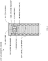
- Fig. 2 illustrates a top view of the resistor-assembly 10 where the laser-trimming operation has removed a portion of the resistor-element 22 and exposes a portion of the substrate 12.
- the laser-trimming 42 reduces a cross sectional area of the resistor-element 22 that increases the resistance-value 40.
- the laser-trimming 42 operation may advantageously be conducted when the resistor-assembly 10 is heated to the temperature above the temperature-threshold 30. This is beneficial because the resistance-value 40 may be more precisely adjusted at the temperature at which the resistor-assembly 10 may operate.
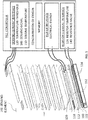
- Fig. 3 illustrates a non-limiting example of a gas-sensing-device 144, hereafter referred to as the device 144, suitable for use to control an internal combustion engine (not shown).
- the device 144 may sense gas-species including oxygen, oxides of nitrogen (NOx), and ammonia, and may use different catalytic-electrodes (not shown) selected to react with the particular gas-species being detected.
- Fig. 3 includes a wide-range-air fuel oxygen sensor (WRAF-sensor), also known as a wide-band sensor, linear oxygen sensor, air-fuel ratio sensor, universal exhaust gas oxygen sensor (UEGO), and wide-band lambda sensor, and is not intended to limit the invention to only the WRAF-sensor.
- WRAF-sensor wide-range-air fuel oxygen sensor
- UEGO universal exhaust gas oxygen sensor
- UEGO universal exhaust gas oxygen sensor
- the device 144 includes a substrate 112 formed of a ceramic-material 114.
- the ceramic-material 114 may include an aluminum oxide 116 (Al 2 O 3 116) with other elements added to the Al 2 O 3 116 for processing and functional requirements, as will be recognized by one skilled in the art.
- the substrate 112 may be used to support circuitry and components of the device 144, as will be described below.
- the device 144 also includes a heater 118 in thermal communication with the substrate 112 that heats the device 144 in response to receiving electrical energy (not shown).
- the heater 118 overlies the substrate 112 and may be applied directly to the substrate 112 by known methods that include, but are not limited to, screen printing, pad-printing, stenciling, etc.
- the heater 118 may include a serpentine-pattern ( Fig. 5 ) to concentrate heat in a particular area of the device 144, such as a sensing-end (not specifically shown).
- the heater 118 may also include heater-leads 120 ( Fig. 5 ) that may be used to electrically connect the heater 118 the electrical energy.
- the heater 18 may be formed of a thick-film ink material such as CN38-019B from Ferro Corporation of Mayfield Heights, Ohio, USA, and processed according to the manufacturer's recommendations.
- the device 144 also includes a sensing-element 146 in thermal communication with the heater 118.
- the sensing-element 146 may detect oxygen in an exhaust-stream (not shown) and outputs a sensing-signal 148 ( Fig. 5 ) based on a concentration of the oxygen in the exhaust-stream, when the sensing-element 146 is heated to a sensing-temperature 150 greater than a temperature-threshold 130.
- the device 144 also includes a resistor-element 122 ( Figs. 3-5 ) that overlies the substrate 112.
- the resistor-element 122 is formed of an ion-conducting material 124 that may include an oxide of an element selected from a list that includes zirconium (Zr), cerium (Ce), uranium (U), and thorium (Th).
- Zr zirconium
- Ce cerium
- U uranium
- Th thorium
- the ion-conducting material 124 conducts ions of a particular element in order to conduct electricity.
- the ion-conducting material 124 is preferably zirconia that may be stabilized with oxides of other elements including, but not limited to yttrium and/or scandium.
- the ion-conducting material 124 is more preferably a yttria stabilized zirconia (YSZ) that includes yttria in concentrations between 1 mol% and 10 mol%, and preferably in concentrations between 4 mol% and 7 mol%.
- YSZ yttria stabilized zirconia
- the properties of YSZ are such that it may conduct oxygen-ions 128 when heated to the temperature above the temperature-threshold 130, and when supplied by a source of oxygen, such as a gas 132 that contains oxygen (e.g. air).
- a source of oxygen such as a gas 132 that contains oxygen (e.g. air).
- the temperature-range in which YSZ conducts ions is understood by those skilled in the art to be between 300°C and 1100°C.
- the resistor-element 122 may be may be applied directly to the substrate 112 by known methods that include, but are not limited to, screen printing, pad-printing, stenciling, etc.
- the resistor-element 122 may be formed of a thick-film ink that is manufactured by any of the known commercial ink manufacturers (e.g. Ferro Corp., Heraeus, Dupont, ESL, etc.) and processed according to the manufacturer's recommendations.
- the device 144 also includes conductive-leads 134 that may be formed of a catalytic-metal 136 including platinum (Pt), palladium (Pd), rhodium (Rh), silver (Ag), nickel (Ni), gold (Au), and their alloys.
- the conductive-leads 134 may be in communication with the gas 132 wherein the properties of the catalytic-metal 136 may reduce oxygen-molecules 138 to oxygen-ions 128 at the interface between the conductive-lead 134 and the resistor-element 122.
- the conductive-leads 134 may also be in electrical contact with the resistor-element 122 to enable the resistor-element 122 to be characterized by a resistance-value 140 that may be influenced by an oxygen-presence in the gas 132.
- the resistance-value 140 may be determined when the resistor-element 122 is heated by the heater 118 such that a resistor-temperature 126 ( Fig. 5 ) is greater than the temperature-threshold 130, whereby the concentration of the oxygen in the exhaust-stream is indicated based on the resistance-value 140 and the sensing-signal 148.
- the conductive-leads 134 may be applied by known methods that include, but are not limited to, screen printing, pad-printing, stenciling, etc.
- the conductive-leads 134 may be formed of a thick-film ink material such as CN38-301 from Ferro Corporation of Mayfield Heights, Ohio, USA, and processed according to the manufacturer's recommendations.
- the resistor-element 122 may also be laser-trimmable 142 such that the resistor-element 122 may be adjusted to a predetermined resistance-value 140.
- Fig. 4 illustrates a top view of the device 144 where the laser-trimming 142 operation has removed a portion of the resistor-element 122 and exposes a portion of the substrate 112.
- the laser-trimming 142 reduces a cross sectional area of the resistor-element 122 that increases the resistance-value 140.
- the laser-trimming 142 operation may advantageously be conducted when the device 144 is heated to the temperature above the temperature-threshold 130. This is beneficial because the resistance-value 140 may be more precisely adjusted at the temperature at which the device 144 may operate.
- the resistor-element 122 may be protected from the environment (e.g. exhaust gasses) by covering the resistor-element 122 with a protective-layer 152 compatible with the substrate 112.
- Figs. 3-4 illustrate the resistor-element 122 overlaid with a cover-layer 154, and a glass-seal 156 that may be dispensed into an aperture 158 defined by the cover-layer 154.
- the cover-layer 154 with the aperture 158 advantageously exposes a portion of the resistor-element 122 to enable the laser-trimming 142 operation on the assembled device 144, after which the glass-seal 156 may be dispensed into the aperture 158 to complete the protective-layer 152.
- Figs. 3 and 5 also illustrate an air-reference-channel 160 interposed between the cover-layer 154 and the conductive-leads 134 that extends along a longitudinal-axis (not specifically shown) of the device 144.
- the air-reference-channel 160 may provide the source of oxygen to the conductive-leads 134 by channeling the gas 132 through the device 144 to the catalytic-metal 136 of the conductive-leads 134.
- the air-reference-channel 160 may be in direct communication with the source of air external to the device 144, or may be in communication with another source of oxygen that may be included in the device 144.
- the device 144 may also include a controller 162 ( Fig. 5 ) in electrical communication with the heater 118, the sensing-element 146, and the resistor-element 122.
- the controller 162 may include a processor (not specifically shown) such as a microprocessor or other control circuitry such as analog and/or digital control circuitry including an application specific integrated circuit (ASIC) for processing data as should be evident to those in the art.
- the controller 162 may include a memory (not specifically shown), including non-volatile memory, such as electrically erasable programmable read-only-memory (EEPROM) for storing one or more routines, thresholds, and captured data. The one or more routines may be executed by the processor to perform steps for operating the device 144 based on signals received by the controller 162 as described herein.
- EEPROM electrically erasable programmable read-only-memory
- the controller 162 may control the electrical energy supplied to the heater 118 to maintain the temperature of the device 144.
- the device 144 may become active above the temperature of 400°C and is preferably maintained at the temperature above the temperature-threshold 130.
- the electrical energy may be controlled by any of the known methods including, but not limited to, a high-side-driver (not shown) or a low-side-driver (not shown) using a pulse-width-modulated signal (not shown).
- a temperature-feedback signal (not shown) may be used by the controller 162 to control the temperature of the device 144 and may include an impedance (not shown) of the sensing-element 146.
- the controller 162 may also determine the resistance-value 140 of the resistor-element 122 when the device 144 is heated to the temperature above the temperature-threshold 130.
- the controller 162 may use any of the known methods to determine the resistance-value 140 that will be apparent to one skilled in the art, and may include an analog to digital converter (ADC, not shown) that may be included in the controller 162.
- ADC analog to digital converter
- the controller 162 may also determine the sensing-signal 148 of the sensing-element 146 when the device 144 is heated to the temperature above the temperature-threshold 130.
- the controller 162 may use an ASIC designed specifically for the purpose of determining the sensing-signal 148, as will be evident to one skilled in the art.
- the sensing-signal 148 may be a voltage or a current that may be measured by another ADC (not shown) that may be included in the controller 162, and may be configured to measure the voltage or the current.
- the controller 162 may also indicate the concentration of the oxygen in the exhaust-stream based on the resistance-value 140 and the sensing-signal 148 through software and/or routines stored in the memory of the controller 162, as will be understood by one skilled in the art.
- a resistor-assembly 10 a gas-sensing-device 144, and a controller 162 for the gas-sensing-device 144 is provided.
- the resistor-assembly 10 is capable of operating at high temperatures that are typical in the exhaust of the internal combustion engine.
- the gas-sensing-device 144 is configured such that the resistor-element 122 is laser-trimmable 142 at the temperature the gas-sensing-device 144 may operate, which enables greater accuracy in correcting the concentration of oxygen in the exhaust-stream.
Landscapes
- Chemical & Material Sciences (AREA)
- Life Sciences & Earth Sciences (AREA)
- Health & Medical Sciences (AREA)
- Engineering & Computer Science (AREA)
- Physics & Mathematics (AREA)
- General Physics & Mathematics (AREA)
- Analytical Chemistry (AREA)
- General Health & Medical Sciences (AREA)
- Pathology (AREA)
- Immunology (AREA)
- Biochemistry (AREA)
- Chemical Kinetics & Catalysis (AREA)
- Combustion & Propulsion (AREA)
- Electrochemistry (AREA)
- Molecular Biology (AREA)
- Food Science & Technology (AREA)
- Medicinal Chemistry (AREA)
- Mechanical Engineering (AREA)
- General Engineering & Computer Science (AREA)
- Materials Engineering (AREA)
- Measuring Oxygen Concentration In Cells (AREA)
- Investigating Or Analyzing Materials By The Use Of Fluid Adsorption Or Reactions (AREA)
Abstract
Description
- This disclosure generally relates to a resistor-assembly, and more particularly relates to a resistor-assembly suitable for use on a gas-sensing-device.
- It is known to use a trim-resistor to adjust an output of a gas-sensor to mitigate the part-to-part variation inherent in a mass produced component. The trim-resistor may be integrated into the sensing-circuitry of the gas-sensor, or may be a separate circuit.
- In accordance with one embodiment, a resistor-assembly is provided. The resistor-assembly includes a substrate, a heater, a resistor-element, and conductive-leads. The substrate is formed of a ceramic-material. The heater heats the resistor-assembly. The resistor-element is formed of an ion-conducting material that overlies the substrate. The conductive-leads are formed of a catalytic-metal that are in communication with a gas and in electrical contact with the resistor-element. The resistor-element wherein a resistance-value influenced by an oxygen-presence in the gas when the resistor-element is heated by the heater such that a resistor-temperature is greater than a temperature-threshold.
- In another embodiment, a gas-sensing-device suitable for use to control an internal combustion engine is provided. The gas-sensing-device includes a substrate, a heater, a sensing-element, a resistor-element, and conductive-leads. The substrate is formed of a ceramic-material. The heater is in thermal communication with the substrate and heats the device in response to receiving electrical energy. The sensing-element is in thermal communication with the heater. The sensing-element detects oxygen in an exhaust-stream. The sensing-element outputs a sensing-signal based on a concentration of the oxygen in the exhaust-stream when the sensing-element is heated to a sensing-temperature greater than a temperature-threshold. The resistor-element is in thermal communication with the heater. The resistor-element is formed of an ion-conducting material that overlies the substrate. The conductive-leads are formed of a catalytic-metal that are in communication with a gas and in electrical contact with the resistor-element. The resistor-element has a resistance-value influenced by an oxygen-presence in the gas when the resistor-element is heated by the heater such that a resistor-temperature is greater than the temperature-threshold. The concentration of the oxygen is indicated based on the resistance-value and the sensing-signal.
- The resistor-assembly may comprise a substrate formed of a ceramic-material;
a heater that heats the resistor-assembly; a resistor-element formed of an ion-conducting material that overlies the substrate; and conductive-leads formed of a catalytic-metal that are in communication with a gas and in electrical contact with the resistor-element, wherein the resistor-element has a resistance-value influenced by an oxygen-presence in the gas when the resistor-element is heated by the heater such that a resistor-temperature is greater than a temperature-threshold. - In the resistor-assembly wherein the resistor-element may be laser-trimmable to a predetermined resistance-value.
- In the resistor-assembly the resistor-element may conduct oxygen-ions when the resistor-element is heated such that the resistor-temperature is greater than the temperature-threshold.
- In the resistor-assembly the ion-conducting material may include an oxide of an element selected from a list that includes zirconium (Zr), cerium (Ce), uranium (U), and thorium (Th).
- In the resistor-assembly the ceramic-material may include an aluminum oxide.
- In rhe resistor-assembly the catalytic-metal may include platinum (Pt), palladium (Pd), rhodium (Rh), silver (Ag), nickel (Ni), gold (Au), and alloys thereof.
- In one embodiment a gas-sensing-device suitable for use to control an internal combustion engine comprises a substrate formed of a ceramic-material; a heater in thermal communication with the substrate, wherein the heater heats the device in response to receiving electrical energy; a sensing-element in thermal communication with the heater, wherein the sensing-element detects oxygen in an exhaust-stream and outputs a sensing-signal based on a concentration of the oxygen in the exhaust-stream when the sensing-element is heated to a sensing-temperature greater than a temperature-threshold; a resistor-element in thermal communication with the heater, said resistor-element formed of an ion-conducting material that overlies the substrate; and conductive-leads formed of a catalytic-metal that are in communication with a gas and in electrical contact with the resistor-element, wherein the resistor-element has a resistance-value influenced by an oxygen-presence in the gas when the resistor-element is heated by the heater such that a resistor-temperature is greater than the temperature-threshold, whereby the concentration of the oxygen in the exhaust-stream is indicated based on the resistance-value and the sensing-signal.
- The device may include a controller in electrical communication with the heater, the sensing-element, and the resistor-element, said controller controls the electrical energy supplied to the heater, determines the resistance-value of the resistor-element, determines the sensing-signal of the sensing-element, and indicates the concentration of the oxygen in the exhaust-stream.
- In the device the resistor-element may be laser-trimmable to a predetermined resistance-value.
- In the device the resister element may conduct oxygen-ions when the resistor-element is heated such that the resistor-temperature is greater than the temperature-threshold.
- In the device the ion-conducting material may include an oxide of an element selected from a list consisting of zirconium (Zr), cerium (Ce), uranium (U), and thorium (Th).
- In the device the ceramic-material may include an aluminum oxide.
- In the device the catalytic-metal may include platinum (Pt), palladium (Pd), rhodium (Rh), silver (Ag), nickel (Ni), gold (Au) and alloys thereof.
- Further features and advantages will appear more clearly on a reading of the following detailed description of the preferred embodiment, which is given by way of non-limiting example only and with reference to the accompanying drawings.
- The present invention will now be described, by way of example with reference to the accompanying drawings, in which:
-
Fig. 1 is a cross section view of a resistor-assembly in accordance with one embodiment; -
Fig. 2 is a top view of the resistor-assembly ofFig. 1 in accordance with one embodiment; -
Fig. 3 is a cross section view of a gas-sensing-device in accordance with one embodiment; -
Fig. 4 is a top view of the gas-sensing-device ofFig. 3 in accordance with one embodiment; and -
Fig 5 . is an illustration of a controller for the gas-sensing-device ofFig. 3 in accordance with one embodiment. - The reference numbers of similar elements in the embodiments shown in the various figures share the last two digits.
-
Fig. 1 illustrates a non-limiting example of a cross section view of a resistor-assembly 10, suitable for use as a trim-resistor on a gas-sensor. The resistor-assembly 10 includes asubstrate 12 formed of a ceramic-material 14. The ceramic-material 14 may include an aluminum oxide 16 (Al2O3 16) with other elements added to the Al2O3 16 for processing and functional requirements, as will be recognized by one skilled in the art. The substrate may be used to support circuitry and components of the resistor-assembly 10, as will be described below. - The resistor-
assembly 10 also includes aheater 18 that heats the resistor-assembly 10. Theheater 18 overlies thesubstrate 12 and may be applied directly to thesubstrate 12 by known methods that include, but are not limited to, screen printing, pad-printing, stenciling, etc. Theheater 18 may include a serpentine-pattern to concentrate heat in a particular area of the resistor-assembly 10. Theheater 18 may also include heater-leads 20 that may be used to electrically connect theheater 18 to a power-source (not shown). Theheater 18 may be formed of a thick-film ink material such as CN38-019B from Ferro Corporation of Mayfield Heights, Ohio, USA, and processed according to the manufacturer's recommendations. - The resistor-
assembly 10 also includes a resistor-element 22 that overlies thesubstrate 12. The resistor-element 22 is formed of an ion-conductingmaterial 24 that may include an oxide of an element selected from a list that includes zirconium (Zr), cerium (Ce), and uranium (U), and Thorium (Th). In contrast to an electron-conducting material (not shown), the ion-conductingmaterial 24 conducts ions of a particular element in order to conduct electricity. The ion-conductingmaterial 24 is preferably zirconia that may be stabilized with oxides of other elements including, but not limited to yttrium and/or scandium. The ion-conductingmaterial 24 is more preferably a yttria stabilized zirconia (YSZ) that includes yttria in concentrations between 1 mol% and 10 mol%, and preferably in concentrations between 4 mol% and 7 mol%. The properties of YSZ are such that it may conduct oxygen-ions 28 when heated to a temperature above a temperature-threshold 30, and when supplied by a source of oxygen, such as agas 32 that contains oxygen (e.g. air). The temperature-range in which YSZ conducts ions is understood by those skilled in the art to be between 300°C and 1100°C. It will also be recognized by those in the art that a rate of ion conduction increases as the temperature of the YSZ increases. Empirical testing has indicated that the temperature-threshold 30 of 700°C provides for a good balance between ion conduction and durability of the resistor-assembly 10. The resistor-element 22 may be may be applied directly to thesubstrate 12 by known methods that include, but are not limited to, screen printing, pad-printing, stenciling, etc. The resistor-element 22 may be formed of a thick-film ink that is manufactured by any of the known commercial ink manufacturers (e.g. Ferro Corp., Heraeus, Dupont, ESL, etc.) and processed according to the manufacturer's recommendations. - The resistor-
assembly 10 also includes conductive-leads 34 that may be formed of a catalytic-metal 36 including platinum (Pt), palladium (Pd), rhodium (Rh), silver (Ag), nickel (Ni), gold (Au), and their alloys. The conductive-leads 34 may be in communication with thegas 32 wherein the properties of the catalytic-metal 36 may reduce oxygen-molecules 38 to oxygen-ions 28 at the interface between the conductive-lead 34 and the resistor-element 22. The conductive-leads 34 may also be in electrical contact with the resistor-element 22 to enable the resistor-element 22 to be characterized by a resistance-value 40 that may be influenced by an oxygen-presence in thegas 32. The resistance-value 40 may be determined when the resistor-element 22 is heated by theheater 18 such that a resistor-temperature 26 is greater than the temperature-threshold 30. The conductive-leads 34 may be may be applied by known methods that include, but are not limited to, screen printing, pad-printing, stenciling, etc. The conductive-leads 34 may be formed of a thick-film ink material such as CN38-301 from Ferro Corporation of Mayfield Heights, Ohio, USA, and processed according to the manufacturer's recommendations. - The resistor-
element 22 may also be laser-trimmable 42 such that the resistor-assembly 10 may be adjusted to a predetermined resistance-value 40.Fig. 2 illustrates a top view of the resistor-assembly 10 where the laser-trimming operation has removed a portion of the resistor-element 22 and exposes a portion of thesubstrate 12. One skilled in the art will recognize that the laser-trimming 42 reduces a cross sectional area of the resistor-element 22 that increases the resistance-value 40. The laser-trimming 42 operation may advantageously be conducted when the resistor-assembly 10 is heated to the temperature above the temperature-threshold 30. This is beneficial because the resistance-value 40 may be more precisely adjusted at the temperature at which the resistor-assembly 10 may operate. -
Fig. 3 illustrates a non-limiting example of a gas-sensing-device 144, hereafter referred to as thedevice 144, suitable for use to control an internal combustion engine (not shown). Thedevice 144 may sense gas-species including oxygen, oxides of nitrogen (NOx), and ammonia, and may use different catalytic-electrodes (not shown) selected to react with the particular gas-species being detected. For the purposes of illustration,Fig. 3 includes a wide-range-air fuel oxygen sensor (WRAF-sensor), also known as a wide-band sensor, linear oxygen sensor, air-fuel ratio sensor, universal exhaust gas oxygen sensor (UEGO), and wide-band lambda sensor, and is not intended to limit the invention to only the WRAF-sensor. - The
device 144 includes asubstrate 112 formed of a ceramic-material 114. The ceramic-material 114 may include an aluminum oxide 116 (Al2O3 116) with other elements added to the Al2O3 116 for processing and functional requirements, as will be recognized by one skilled in the art. Thesubstrate 112 may be used to support circuitry and components of thedevice 144, as will be described below. - The
device 144 also includes aheater 118 in thermal communication with thesubstrate 112 that heats thedevice 144 in response to receiving electrical energy (not shown). Theheater 118 overlies thesubstrate 112 and may be applied directly to thesubstrate 112 by known methods that include, but are not limited to, screen printing, pad-printing, stenciling, etc. Theheater 118 may include a serpentine-pattern (Fig. 5 ) to concentrate heat in a particular area of thedevice 144, such as a sensing-end (not specifically shown). Theheater 118 may also include heater-leads 120 (Fig. 5 ) that may be used to electrically connect theheater 118 the electrical energy. Theheater 18 may be formed of a thick-film ink material such as CN38-019B from Ferro Corporation of Mayfield Heights, Ohio, USA, and processed according to the manufacturer's recommendations. - The
device 144 also includes a sensing-element 146 in thermal communication with theheater 118. The sensing-element 146 may detect oxygen in an exhaust-stream (not shown) and outputs a sensing-signal 148 (Fig. 5 ) based on a concentration of the oxygen in the exhaust-stream, when the sensing-element 146 is heated to a sensing-temperature 150 greater than a temperature-threshold 130. - The
device 144 also includes a resistor-element 122 (Figs. 3-5 ) that overlies thesubstrate 112. The resistor-element 122 is formed of an ion-conductingmaterial 124 that may include an oxide of an element selected from a list that includes zirconium (Zr), cerium (Ce), uranium (U), and thorium (Th). In contrast to an electron-conducting material (not shown), the ion-conductingmaterial 124 conducts ions of a particular element in order to conduct electricity. The ion-conductingmaterial 124 is preferably zirconia that may be stabilized with oxides of other elements including, but not limited to yttrium and/or scandium. The ion-conductingmaterial 124 is more preferably a yttria stabilized zirconia (YSZ) that includes yttria in concentrations between 1 mol% and 10 mol%, and preferably in concentrations between 4 mol% and 7 mol%. The properties of YSZ are such that it may conduct oxygen-ions 128 when heated to the temperature above the temperature-threshold 130, and when supplied by a source of oxygen, such as agas 132 that contains oxygen (e.g. air). The temperature-range in which YSZ conducts ions is understood by those skilled in the art to be between 300°C and 1100°C. It will also be recognized by those in the art that a rate of ion conduction increases as the temperature of the YSZ increases. Empirical testing has indicated that the temperature-threshold 130 of 700°C provides for a good balance between ion conduction and durability of thedevice 144. The resistor-element 122 may be may be applied directly to thesubstrate 112 by known methods that include, but are not limited to, screen printing, pad-printing, stenciling, etc. The resistor-element 122 may be formed of a thick-film ink that is manufactured by any of the known commercial ink manufacturers (e.g. Ferro Corp., Heraeus, Dupont, ESL, etc.) and processed according to the manufacturer's recommendations. - The
device 144 also includes conductive-leads 134 that may be formed of a catalytic-metal 136 including platinum (Pt), palladium (Pd), rhodium (Rh), silver (Ag), nickel (Ni), gold (Au), and their alloys. The conductive-leads 134 may be in communication with thegas 132 wherein the properties of the catalytic-metal 136 may reduce oxygen-molecules 138 to oxygen-ions 128 at the interface between the conductive-lead 134 and the resistor-element 122. The conductive-leads 134 may also be in electrical contact with the resistor-element 122 to enable the resistor-element 122 to be characterized by a resistance-value 140 that may be influenced by an oxygen-presence in thegas 132. The resistance-value 140 may be determined when the resistor-element 122 is heated by theheater 118 such that a resistor-temperature 126 (Fig. 5 ) is greater than the temperature-threshold 130, whereby the concentration of the oxygen in the exhaust-stream is indicated based on the resistance-value 140 and the sensing-signal 148. The conductive-leads 134 may be applied by known methods that include, but are not limited to, screen printing, pad-printing, stenciling, etc. The conductive-leads 134 may be formed of a thick-film ink material such as CN38-301 from Ferro Corporation of Mayfield Heights, Ohio, USA, and processed according to the manufacturer's recommendations. - The resistor-
element 122 may also be laser-trimmable 142 such that the resistor-element 122 may be adjusted to a predetermined resistance-value 140.Fig. 4 illustrates a top view of thedevice 144 where the laser-trimming 142 operation has removed a portion of the resistor-element 122 and exposes a portion of thesubstrate 112. One skilled in the art will recognize the laser-trimming 142 reduces a cross sectional area of the resistor-element 122 that increases the resistance-value 140. The laser-trimming 142 operation may advantageously be conducted when thedevice 144 is heated to the temperature above the temperature-threshold 130. This is beneficial because the resistance-value 140 may be more precisely adjusted at the temperature at which thedevice 144 may operate. - The resistor-
element 122 may be protected from the environment (e.g. exhaust gasses) by covering the resistor-element 122 with a protective-layer 152 compatible with thesubstrate 112.Figs. 3-4 illustrate the resistor-element 122 overlaid with a cover-layer 154, and a glass-seal 156 that may be dispensed into anaperture 158 defined by the cover-layer 154. The cover-layer 154 with theaperture 158 advantageously exposes a portion of the resistor-element 122 to enable the laser-trimming 142 operation on the assembleddevice 144, after which the glass-seal 156 may be dispensed into theaperture 158 to complete the protective-layer 152. -
Figs. 3 and5 also illustrate an air-reference-channel 160 interposed between the cover-layer 154 and the conductive-leads 134 that extends along a longitudinal-axis (not specifically shown) of thedevice 144. The air-reference-channel 160 may provide the source of oxygen to the conductive-leads 134 by channeling thegas 132 through thedevice 144 to the catalytic-metal 136 of the conductive-leads 134. The air-reference-channel 160 may be in direct communication with the source of air external to thedevice 144, or may be in communication with another source of oxygen that may be included in thedevice 144. - The
device 144 may also include a controller 162 (Fig. 5 ) in electrical communication with theheater 118, the sensing-element 146, and the resistor-element 122. Thecontroller 162 may include a processor (not specifically shown) such as a microprocessor or other control circuitry such as analog and/or digital control circuitry including an application specific integrated circuit (ASIC) for processing data as should be evident to those in the art. Thecontroller 162 may include a memory (not specifically shown), including non-volatile memory, such as electrically erasable programmable read-only-memory (EEPROM) for storing one or more routines, thresholds, and captured data. The one or more routines may be executed by the processor to perform steps for operating thedevice 144 based on signals received by thecontroller 162 as described herein. - The
controller 162 may control the electrical energy supplied to theheater 118 to maintain the temperature of thedevice 144. Thedevice 144 may become active above the temperature of 400°C and is preferably maintained at the temperature above the temperature-threshold 130. The electrical energy may be controlled by any of the known methods including, but not limited to, a high-side-driver (not shown) or a low-side-driver (not shown) using a pulse-width-modulated signal (not shown). A temperature-feedback signal (not shown) may be used by thecontroller 162 to control the temperature of thedevice 144 and may include an impedance (not shown) of the sensing-element 146. - The
controller 162 may also determine the resistance-value 140 of the resistor-element 122 when thedevice 144 is heated to the temperature above the temperature-threshold 130. Thecontroller 162 may use any of the known methods to determine the resistance-value 140 that will be apparent to one skilled in the art, and may include an analog to digital converter (ADC, not shown) that may be included in thecontroller 162. - The
controller 162 may also determine the sensing-signal 148 of the sensing-element 146 when thedevice 144 is heated to the temperature above the temperature-threshold 130. Thecontroller 162 may use an ASIC designed specifically for the purpose of determining the sensing-signal 148, as will be evident to one skilled in the art. The sensing-signal 148 may be a voltage or a current that may be measured by another ADC (not shown) that may be included in thecontroller 162, and may be configured to measure the voltage or the current. - The
controller 162 may also indicate the concentration of the oxygen in the exhaust-stream based on the resistance-value 140 and the sensing-signal 148 through software and/or routines stored in the memory of thecontroller 162, as will be understood by one skilled in the art. - Accordingly, a resistor-
assembly 10, a gas-sensing-device 144, and acontroller 162 for the gas-sensing-device 144 is provided. The resistor-assembly 10 is capable of operating at high temperatures that are typical in the exhaust of the internal combustion engine. The gas-sensing-device 144 is configured such that the resistor-element 122 is laser-trimmable 142 at the temperature the gas-sensing-device 144 may operate, which enables greater accuracy in correcting the concentration of oxygen in the exhaust-stream. - While this invention has been described in terms of the preferred embodiments thereof, it is not intended to be so limited, but rather only to the extent set forth in the claims that follow. While this invention has been described in terms of the preferred embodiments thereof, it is not intended to be so limited, but rather only to the extent set forth in the claims that follow. Moreover, the use of the terms first, second, etc. does not denote any order of importance, but rather the terms first, second, etc. are used to distinguish one element from another. Furthermore, the use of the terms a, an, etc. do not denote a limitation of quantity, but rather denote the presence of at least one of the referenced items. Additionally, directional terms such as upper, lower, etc. do not denote any particular orientation, but rather the terms upper, lower, etc. are used to distinguish one element from another and locational establish a relationship between the various elements.
Claims (13)
- A resistor-assembly (10), comprising:a substrate (12) formed of a ceramic-material (14);a heater (18) that heats the resistor-assembly (10);a resistor-element (22) formed of an ion-conducting material (24) that overlies the substrate (12); andconductive-leads (34) formed of a catalytic-metal (36) that are in communication with a gas (32) and in electrical contact with the resistor-element (22), wherein the resistor-element (22) is characterized by a resistance-value (40) influenced by an oxygen-presence in the gas (32) when the resistor-element (22) is heated by the heater (18) such that a resistor-temperature (26) is greater than a temperature-threshold (30).
- The resistor-assembly (10) in accordance with claim 1, wherein the resistor-element (22) is laser-trimmable (42) to a predetermined resistance-value (40).
- The resistor-assembly (10) in accordance with claim 1 or 2, wherein the resistor-element (22) conducts oxygen-ions (28) when the resistor-element (22) is heated such that the resistor-temperature (26) is greater than the temperature-threshold (30).
- The resistor-assembly (10) in accordance with claim 3, wherein the ion-conducting material (24) includes an oxide of an element selected from a list that includes zirconium (Zr), cerium (Ce), uranium (U), and thorium (Th).
- The resistor-assembly (10) in accordance with any of claims 1-4, wherein the ceramic-material (14) includes an aluminum oxide (16).
- The resistor-assembly (10) in accordance with any of claims 1-5, wherein the catalytic-metal (36) includes platinum (Pt), palladium (Pd), rhodium (Rh), silver (Ag), nickel (Ni), gold (Au), and alloys thereof.
- A gas-sensing-device (144) suitable for use to control an internal combustion engine, said device (144) comprising:a substrate (112) formed of a ceramic-material (114);a heater (118) in thermal communication with the substrate (112), wherein the heater (118) heats the device (144) in response to receiving electrical energy;a sensing-element (146) in thermal communication with the heater (118), wherein the sensing-element (146) detects oxygen in an exhaust-stream and outputs a sensing-signal (148) based on a concentration of the oxygen in the exhaust-stream when the sensing-element (146) is heated to a sensing-temperature (150) greater than a temperature-threshold (130);a resistor-element (122) in thermal communication with the heater (118), said resistor-element (122) formed of an ion-conducting material (124) that overlies the substrate (112); andconductive-leads (134) formed of a catalytic-metal (136) that are in communication with a gas (132) and in electrical contact with the resistor-element (122), wherein the resistor-element (122) is characterized by a resistance-value (140) influenced by an oxygen-presence in the gas (132) when the resistor-element (122) is heated by the heater (118) such that a resistor-temperature (126) is greater than the temperature-threshold (130), whereby the concentration of the oxygen in the exhaust-stream is indicated based on the resistance-value (140) and the sensing-signal (148).
- The device (144) in accordance with claim 7, wherein the device (144) includes a controller (162) in electrical communication with the heater (118), the sensing-element (146), and the resistor-element (122), said controller (162) controls the electrical energy supplied to the heater (118), determines the resistance-value (140) of the resistor-element (122), determines the sensing-signal (148) of the sensing-element (146), and indicates the concentration of the oxygen in the exhaust-stream.
- The device (144) in accordance with claims 7 or 8, wherein the resistor-element (122) is laser-trimmable (142) to a predetermined resistance-value (140).
- The device (144) in accordance with any of claims 7-9, wherein the resistor-element (122) conducts oxygen-ions (128) when the resistor-element (122) is heated such that the resistor-temperature (126) is greater than the temperature-threshold (130).
- The device (144) in accordance with claim 10, wherein the ion-conducting material (124) includes an oxide of an element selected from a list consisting of zirconium (Zr), cerium (Ce), uranium (U), and thorium (Th).
- The device (144) in accordance with any of claims 7-11, wherein the ceramic-material (114) includes an aluminum oxide (116).
- The device (144) in accordance with any of claims 7-12, wherein the catalytic-metal (136) includes platinum (Pt), palladium (Pd), rhodium (Rh), silver (Ag), nickel (Ni), gold (Au) and alloys thereof.
Applications Claiming Priority (1)
| Application Number | Priority Date | Filing Date | Title |
|---|---|---|---|
| US15/598,457 US11307159B2 (en) | 2017-05-18 | 2017-05-18 | Ionic-conducting resistor for exhaust constituent sensors |
Publications (2)
| Publication Number | Publication Date |
|---|---|
| EP3404406A1 true EP3404406A1 (en) | 2018-11-21 |
| EP3404406B1 EP3404406B1 (en) | 2023-02-15 |
Family
ID=62196410
Family Applications (1)
| Application Number | Title | Priority Date | Filing Date |
|---|---|---|---|
| EP18172772.8A Active EP3404406B1 (en) | 2017-05-18 | 2018-05-16 | Ionic-conducting resistor for exhaust constituent sensors |
Country Status (2)
| Country | Link |
|---|---|
| US (1) | US11307159B2 (en) |
| EP (1) | EP3404406B1 (en) |
Families Citing this family (1)
| Publication number | Priority date | Publication date | Assignee | Title |
|---|---|---|---|---|
| US11391232B2 (en) | 2019-10-23 | 2022-07-19 | Delphi Technologies Ip Limited | Particulate matter sensor |
Citations (4)
| Publication number | Priority date | Publication date | Assignee | Title |
|---|---|---|---|---|
| US5389218A (en) * | 1989-01-24 | 1995-02-14 | Gas Research Institute | Process for operating a solid-state oxygen microsensor |
| JP2001305100A (en) * | 2000-04-25 | 2001-10-31 | Matsushita Electric Ind Co Ltd | Gas sensor |
| US20110214988A1 (en) * | 2010-03-02 | 2011-09-08 | Ngk Spark Plug Co., Ltd. | Gas sensor element, gas sensor and control system of gas sensor |
| JP2015068820A (en) * | 2013-10-01 | 2015-04-13 | 日本特殊陶業株式会社 | Gas sensor device |
Family Cites Families (24)
| Publication number | Priority date | Publication date | Assignee | Title |
|---|---|---|---|---|
| US2673228A (en) | 1950-09-15 | 1954-03-23 | Norton Co | Induction furnace with high-temperature resistor |
| US3768157A (en) | 1971-03-31 | 1973-10-30 | Trw Inc | Process of manufacture of semiconductor product |
| US4176445A (en) | 1977-06-03 | 1979-12-04 | Angstrohm Precision, Inc. | Metal foil resistor |
| FR2404218A1 (en) | 1977-09-26 | 1979-04-20 | Bendix Autolite Corp | TEMPERATURE COMPENSATED OXYGEN SENSOR |
| US4233033A (en) | 1979-09-19 | 1980-11-11 | Bendix Autolite Corporation | Method and apparatus for measuring the O2 content of a gas |
| CA1127870A (en) | 1979-09-19 | 1982-07-20 | Walter F. Datwyler, Jr. | Temperature compensated titania type oxygen sensor |
| US4298855A (en) | 1980-08-26 | 1981-11-03 | Honeywell Inc. | Conductive polymer film humidity sensor |
| US4385611A (en) | 1981-04-01 | 1983-05-31 | The Bendix Corporation | Fuel injection system with fuel mapping |
| US4505807A (en) * | 1982-02-22 | 1985-03-19 | Ngk Spark Plug Co., Ltd. | Oxygen sensor |
| JPS6036948A (en) * | 1983-08-09 | 1985-02-26 | Ngk Insulators Ltd | Electrochemical device |
| JPH07226301A (en) | 1994-02-10 | 1995-08-22 | Tama Electric Co Ltd | Resistor |
| JPH09232118A (en) | 1996-02-28 | 1997-09-05 | Matsushita Electric Works Ltd | Semiconductor device |
| US6208233B1 (en) | 2000-03-03 | 2001-03-27 | Delphi Technologies, Inc. | Trim resistor connector and sensor system |
| US6562747B2 (en) * | 2000-12-19 | 2003-05-13 | Delphi Technologies, Inc. | Gas sensor electrolyte |
| US20040095225A1 (en) | 2001-03-19 | 2004-05-20 | Nelson Charles Scott | Independently housed trim resistor and a method for fabricating same |
| US7279133B2 (en) | 2001-12-20 | 2007-10-09 | Delphi Technologies, Inc. | Planar sensor and a method for measuring the temperature of same |
| US6709558B2 (en) * | 2002-05-08 | 2004-03-23 | Delphi Technologies, Inc. | Gas sensor |
| US7048844B2 (en) * | 2002-11-15 | 2006-05-23 | Delphi Technologies, Inc. | Gas sensor and method for use thereof |
| US20050017760A1 (en) | 2003-07-22 | 2005-01-27 | International Rectifier Corporation | Current sense shunt resistor circuit |
| US20070146114A1 (en) | 2005-12-28 | 2007-06-28 | Nelson Charles S | Trim resistor assembly and method for making the same |
| US7161461B1 (en) | 2006-03-07 | 2007-01-09 | Delphi Technologies, Inc. | Injection molded trim resistor assembly |
| US7478002B2 (en) | 2007-01-26 | 2009-01-13 | Delphi Technologies, Inc. | Apparatus and method for trimming multiple sensing elements with a single trim resistor |
| CA2717032A1 (en) * | 2008-02-28 | 2009-09-03 | Nextech Materials, Ltd. | Amperometric electrochemical cells and sensors |
| US20160216223A1 (en) * | 2015-01-22 | 2016-07-28 | Delphi Technologies, Inc. | Multisensing Multiparameter Design Using Dynamic Parallel Resistances on Sensing Element Substrate |
-
2017
- 2017-05-18 US US15/598,457 patent/US11307159B2/en active Active
-
2018
- 2018-05-16 EP EP18172772.8A patent/EP3404406B1/en active Active
Patent Citations (4)
| Publication number | Priority date | Publication date | Assignee | Title |
|---|---|---|---|---|
| US5389218A (en) * | 1989-01-24 | 1995-02-14 | Gas Research Institute | Process for operating a solid-state oxygen microsensor |
| JP2001305100A (en) * | 2000-04-25 | 2001-10-31 | Matsushita Electric Ind Co Ltd | Gas sensor |
| US20110214988A1 (en) * | 2010-03-02 | 2011-09-08 | Ngk Spark Plug Co., Ltd. | Gas sensor element, gas sensor and control system of gas sensor |
| JP2015068820A (en) * | 2013-10-01 | 2015-04-13 | 日本特殊陶業株式会社 | Gas sensor device |
Also Published As
| Publication number | Publication date |
|---|---|
| EP3404406B1 (en) | 2023-02-15 |
| US11307159B2 (en) | 2022-04-19 |
| US20180335398A1 (en) | 2018-11-22 |
Similar Documents
| Publication | Publication Date | Title |
|---|---|---|
| JP3871497B2 (en) | Gas sensor | |
| US20120145543A1 (en) | Multigas sensor | |
| JP5134399B2 (en) | Gas sensor and gas sensor control device | |
| JP2009540334A5 (en) | ||
| JP2003083933A (en) | Ammonia gas concentration measurement device | |
| US4528086A (en) | Oxygen sensor with heater | |
| JP5033017B2 (en) | Ammonia gas sensor | |
| US6770180B1 (en) | Electrochemical measuring sensor | |
| EP3404406B1 (en) | Ionic-conducting resistor for exhaust constituent sensors | |
| JP2011047756A (en) | Ammonia gas sensor | |
| CN105765377B (en) | Oxygen sensor element | |
| JP5281988B2 (en) | Ammonia gas sensor | |
| JP5001214B2 (en) | Gas sensor element and gas sensor | |
| US6085575A (en) | Process for the determination of the exhaust gas temperature and of the air/fuel ratio lambda and a sensor arrangement for execution of the process | |
| JP2011180042A (en) | Device for control of gas sensor, and control system of gas sensor | |
| US6942772B1 (en) | Measuring sensor for the determination of a concentration of gas constituents in gaseous mixtures | |
| JP5085993B2 (en) | Hybrid potential sensor for detecting various gases in a gas mixture and method for detecting various gases in a gas mixture by the sensor | |
| JP5927647B2 (en) | Gas detector | |
| JP5488289B2 (en) | Oxygen sensor element | |
| JP2009243942A (en) | Hydrocarbon concentration measuring sensor element and hydrocarbon concentration measuring method | |
| JP4625261B2 (en) | Sensor element of gas sensor | |
| US11274974B2 (en) | Temperature sensor | |
| JP2004020377A (en) | Contact combustion type gas sensor | |
| US4485369A (en) | Sensor for measuring air-fuel ratio | |
| JP5645607B2 (en) | Nitrogen oxide sensor element and nitrogen oxide detection method |
Legal Events
| Date | Code | Title | Description |
|---|---|---|---|
| PUAI | Public reference made under article 153(3) epc to a published international application that has entered the european phase |
Free format text: ORIGINAL CODE: 0009012 |
|
| STAA | Information on the status of an ep patent application or granted ep patent |
Free format text: STATUS: THE APPLICATION HAS BEEN PUBLISHED |
|
| AK | Designated contracting states |
Kind code of ref document: A1 Designated state(s): AL AT BE BG CH CY CZ DE DK EE ES FI FR GB GR HR HU IE IS IT LI LT LU LV MC MK MT NL NO PL PT RO RS SE SI SK SM TR |
|
| AX | Request for extension of the european patent |
Extension state: BA ME |
|
| STAA | Information on the status of an ep patent application or granted ep patent |
Free format text: STATUS: REQUEST FOR EXAMINATION WAS MADE |
|
| 17P | Request for examination filed |
Effective date: 20190521 |
|
| RBV | Designated contracting states (corrected) |
Designated state(s): AL AT BE BG CH CY CZ DE DK EE ES FI FR GB GR HR HU IE IS IT LI LT LU LV MC MK MT NL NO PL PT RO RS SE SI SK SM TR |
|
| STAA | Information on the status of an ep patent application or granted ep patent |
Free format text: STATUS: EXAMINATION IS IN PROGRESS |
|
| 17Q | First examination report despatched |
Effective date: 20220407 |
|
| REG | Reference to a national code |
Ref country code: DE Ref legal event code: R079 Ref document number: 602018046093 Country of ref document: DE Free format text: PREVIOUS MAIN CLASS: G01N0027406000 Ipc: G01M0015100000 |
|
| GRAP | Despatch of communication of intention to grant a patent |
Free format text: ORIGINAL CODE: EPIDOSNIGR1 |
|
| STAA | Information on the status of an ep patent application or granted ep patent |
Free format text: STATUS: GRANT OF PATENT IS INTENDED |
|
| RIC1 | Information provided on ipc code assigned before grant |
Ipc: G01N 33/00 20060101ALI20220819BHEP Ipc: G01N 27/417 20060101ALI20220819BHEP Ipc: G01N 27/406 20060101ALI20220819BHEP Ipc: G01N 27/407 20060101ALI20220819BHEP Ipc: G01M 15/10 20060101AFI20220819BHEP |
|
| INTG | Intention to grant announced |
Effective date: 20220927 |
|
| RIN1 | Information on inventor provided before grant (corrected) |
Inventor name: POLIKARPUS, KAIUS K. Inventor name: COVARRUBIAS, ALFREDO I. |
|
| GRAS | Grant fee paid |
Free format text: ORIGINAL CODE: EPIDOSNIGR3 |
|
| GRAA | (expected) grant |
Free format text: ORIGINAL CODE: 0009210 |
|
| STAA | Information on the status of an ep patent application or granted ep patent |
Free format text: STATUS: THE PATENT HAS BEEN GRANTED |
|
| AK | Designated contracting states |
Kind code of ref document: B1 Designated state(s): AL AT BE BG CH CY CZ DE DK EE ES FI FR GB GR HR HU IE IS IT LI LT LU LV MC MK MT NL NO PL PT RO RS SE SI SK SM TR |
|
| REG | Reference to a national code |
Ref country code: CH Ref legal event code: EP Ref country code: GB Ref legal event code: FG4D |
|
| REG | Reference to a national code |
Ref country code: DE Ref legal event code: R096 Ref document number: 602018046093 Country of ref document: DE |
|
| REG | Reference to a national code |
Ref country code: AT Ref legal event code: REF Ref document number: 1548457 Country of ref document: AT Kind code of ref document: T Effective date: 20230315 Ref country code: IE Ref legal event code: FG4D |
|
| REG | Reference to a national code |
Ref country code: LT Ref legal event code: MG9D |
|
| P01 | Opt-out of the competence of the unified patent court (upc) registered |
Effective date: 20230327 |
|
| REG | Reference to a national code |
Ref country code: NL Ref legal event code: MP Effective date: 20230215 |
|
| REG | Reference to a national code |
Ref country code: AT Ref legal event code: MK05 Ref document number: 1548457 Country of ref document: AT Kind code of ref document: T Effective date: 20230215 |
|
| PG25 | Lapsed in a contracting state [announced via postgrant information from national office to epo] |
Ref country code: RS Free format text: LAPSE BECAUSE OF FAILURE TO SUBMIT A TRANSLATION OF THE DESCRIPTION OR TO PAY THE FEE WITHIN THE PRESCRIBED TIME-LIMIT Effective date: 20230215 Ref country code: PT Free format text: LAPSE BECAUSE OF FAILURE TO SUBMIT A TRANSLATION OF THE DESCRIPTION OR TO PAY THE FEE WITHIN THE PRESCRIBED TIME-LIMIT Effective date: 20230615 Ref country code: NO Free format text: LAPSE BECAUSE OF FAILURE TO SUBMIT A TRANSLATION OF THE DESCRIPTION OR TO PAY THE FEE WITHIN THE PRESCRIBED TIME-LIMIT Effective date: 20230515 Ref country code: NL Free format text: LAPSE BECAUSE OF FAILURE TO SUBMIT A TRANSLATION OF THE DESCRIPTION OR TO PAY THE FEE WITHIN THE PRESCRIBED TIME-LIMIT Effective date: 20230215 Ref country code: LV Free format text: LAPSE BECAUSE OF FAILURE TO SUBMIT A TRANSLATION OF THE DESCRIPTION OR TO PAY THE FEE WITHIN THE PRESCRIBED TIME-LIMIT Effective date: 20230215 Ref country code: LT Free format text: LAPSE BECAUSE OF FAILURE TO SUBMIT A TRANSLATION OF THE DESCRIPTION OR TO PAY THE FEE WITHIN THE PRESCRIBED TIME-LIMIT Effective date: 20230215 Ref country code: HR Free format text: LAPSE BECAUSE OF FAILURE TO SUBMIT A TRANSLATION OF THE DESCRIPTION OR TO PAY THE FEE WITHIN THE PRESCRIBED TIME-LIMIT Effective date: 20230215 Ref country code: ES Free format text: LAPSE BECAUSE OF FAILURE TO SUBMIT A TRANSLATION OF THE DESCRIPTION OR TO PAY THE FEE WITHIN THE PRESCRIBED TIME-LIMIT Effective date: 20230215 Ref country code: AT Free format text: LAPSE BECAUSE OF FAILURE TO SUBMIT A TRANSLATION OF THE DESCRIPTION OR TO PAY THE FEE WITHIN THE PRESCRIBED TIME-LIMIT Effective date: 20230215 |
|
| PG25 | Lapsed in a contracting state [announced via postgrant information from national office to epo] |
Ref country code: SE Free format text: LAPSE BECAUSE OF FAILURE TO SUBMIT A TRANSLATION OF THE DESCRIPTION OR TO PAY THE FEE WITHIN THE PRESCRIBED TIME-LIMIT Effective date: 20230215 Ref country code: PL Free format text: LAPSE BECAUSE OF FAILURE TO SUBMIT A TRANSLATION OF THE DESCRIPTION OR TO PAY THE FEE WITHIN THE PRESCRIBED TIME-LIMIT Effective date: 20230215 Ref country code: IS Free format text: LAPSE BECAUSE OF FAILURE TO SUBMIT A TRANSLATION OF THE DESCRIPTION OR TO PAY THE FEE WITHIN THE PRESCRIBED TIME-LIMIT Effective date: 20230615 Ref country code: GR Free format text: LAPSE BECAUSE OF FAILURE TO SUBMIT A TRANSLATION OF THE DESCRIPTION OR TO PAY THE FEE WITHIN THE PRESCRIBED TIME-LIMIT Effective date: 20230516 Ref country code: FI Free format text: LAPSE BECAUSE OF FAILURE TO SUBMIT A TRANSLATION OF THE DESCRIPTION OR TO PAY THE FEE WITHIN THE PRESCRIBED TIME-LIMIT Effective date: 20230215 |
|
| PG25 | Lapsed in a contracting state [announced via postgrant information from national office to epo] |
Ref country code: SM Free format text: LAPSE BECAUSE OF FAILURE TO SUBMIT A TRANSLATION OF THE DESCRIPTION OR TO PAY THE FEE WITHIN THE PRESCRIBED TIME-LIMIT Effective date: 20230215 Ref country code: RO Free format text: LAPSE BECAUSE OF FAILURE TO SUBMIT A TRANSLATION OF THE DESCRIPTION OR TO PAY THE FEE WITHIN THE PRESCRIBED TIME-LIMIT Effective date: 20230215 Ref country code: EE Free format text: LAPSE BECAUSE OF FAILURE TO SUBMIT A TRANSLATION OF THE DESCRIPTION OR TO PAY THE FEE WITHIN THE PRESCRIBED TIME-LIMIT Effective date: 20230215 Ref country code: DK Free format text: LAPSE BECAUSE OF FAILURE TO SUBMIT A TRANSLATION OF THE DESCRIPTION OR TO PAY THE FEE WITHIN THE PRESCRIBED TIME-LIMIT Effective date: 20230215 Ref country code: CZ Free format text: LAPSE BECAUSE OF FAILURE TO SUBMIT A TRANSLATION OF THE DESCRIPTION OR TO PAY THE FEE WITHIN THE PRESCRIBED TIME-LIMIT Effective date: 20230215 |
|
| REG | Reference to a national code |
Ref country code: DE Ref legal event code: R097 Ref document number: 602018046093 Country of ref document: DE |
|
| PG25 | Lapsed in a contracting state [announced via postgrant information from national office to epo] |
Ref country code: SK Free format text: LAPSE BECAUSE OF FAILURE TO SUBMIT A TRANSLATION OF THE DESCRIPTION OR TO PAY THE FEE WITHIN THE PRESCRIBED TIME-LIMIT Effective date: 20230215 |
|
| PLBE | No opposition filed within time limit |
Free format text: ORIGINAL CODE: 0009261 |
|
| STAA | Information on the status of an ep patent application or granted ep patent |
Free format text: STATUS: NO OPPOSITION FILED WITHIN TIME LIMIT |
|
| REG | Reference to a national code |
Ref country code: CH Ref legal event code: PL |
|
| PG25 | Lapsed in a contracting state [announced via postgrant information from national office to epo] |
Ref country code: MC Free format text: LAPSE BECAUSE OF FAILURE TO SUBMIT A TRANSLATION OF THE DESCRIPTION OR TO PAY THE FEE WITHIN THE PRESCRIBED TIME-LIMIT Effective date: 20230215 |
|
| 26N | No opposition filed |
Effective date: 20231116 |
|
| GBPC | Gb: european patent ceased through non-payment of renewal fee |
Effective date: 20230516 |
|
| REG | Reference to a national code |
Ref country code: BE Ref legal event code: MM Effective date: 20230531 |
|
| PG25 | Lapsed in a contracting state [announced via postgrant information from national office to epo] |
Ref country code: SI Free format text: LAPSE BECAUSE OF FAILURE TO SUBMIT A TRANSLATION OF THE DESCRIPTION OR TO PAY THE FEE WITHIN THE PRESCRIBED TIME-LIMIT Effective date: 20230215 Ref country code: MC Free format text: LAPSE BECAUSE OF FAILURE TO SUBMIT A TRANSLATION OF THE DESCRIPTION OR TO PAY THE FEE WITHIN THE PRESCRIBED TIME-LIMIT Effective date: 20230215 Ref country code: LU Free format text: LAPSE BECAUSE OF NON-PAYMENT OF DUE FEES Effective date: 20230516 Ref country code: LI Free format text: LAPSE BECAUSE OF NON-PAYMENT OF DUE FEES Effective date: 20230531 Ref country code: CH Free format text: LAPSE BECAUSE OF NON-PAYMENT OF DUE FEES Effective date: 20230531 |
|
| REG | Reference to a national code |
Ref country code: IE Ref legal event code: MM4A |
|
| PG25 | Lapsed in a contracting state [announced via postgrant information from national office to epo] |
Ref country code: IE Free format text: LAPSE BECAUSE OF NON-PAYMENT OF DUE FEES Effective date: 20230516 |
|
| PG25 | Lapsed in a contracting state [announced via postgrant information from national office to epo] |
Ref country code: IE Free format text: LAPSE BECAUSE OF NON-PAYMENT OF DUE FEES Effective date: 20230516 Ref country code: GB Free format text: LAPSE BECAUSE OF NON-PAYMENT OF DUE FEES Effective date: 20230516 |
|
| PG25 | Lapsed in a contracting state [announced via postgrant information from national office to epo] |
Ref country code: IT Free format text: LAPSE BECAUSE OF FAILURE TO SUBMIT A TRANSLATION OF THE DESCRIPTION OR TO PAY THE FEE WITHIN THE PRESCRIBED TIME-LIMIT Effective date: 20230215 Ref country code: BE Free format text: LAPSE BECAUSE OF NON-PAYMENT OF DUE FEES Effective date: 20230531 |
|
| PG25 | Lapsed in a contracting state [announced via postgrant information from national office to epo] |
Ref country code: BG Free format text: LAPSE BECAUSE OF FAILURE TO SUBMIT A TRANSLATION OF THE DESCRIPTION OR TO PAY THE FEE WITHIN THE PRESCRIBED TIME-LIMIT Effective date: 20230215 |
|
| PG25 | Lapsed in a contracting state [announced via postgrant information from national office to epo] |
Ref country code: BG Free format text: LAPSE BECAUSE OF FAILURE TO SUBMIT A TRANSLATION OF THE DESCRIPTION OR TO PAY THE FEE WITHIN THE PRESCRIBED TIME-LIMIT Effective date: 20230215 |
|
| PGFP | Annual fee paid to national office [announced via postgrant information from national office to epo] |
Ref country code: DE Payment date: 20250409 Year of fee payment: 8 |
|
| PGFP | Annual fee paid to national office [announced via postgrant information from national office to epo] |
Ref country code: FR Payment date: 20250409 Year of fee payment: 8 |
|
| PG25 | Lapsed in a contracting state [announced via postgrant information from national office to epo] |
Ref country code: CY Free format text: LAPSE BECAUSE OF FAILURE TO SUBMIT A TRANSLATION OF THE DESCRIPTION OR TO PAY THE FEE WITHIN THE PRESCRIBED TIME-LIMIT; INVALID AB INITIO Effective date: 20180516 |
|
| PG25 | Lapsed in a contracting state [announced via postgrant information from national office to epo] |
Ref country code: HU Free format text: LAPSE BECAUSE OF FAILURE TO SUBMIT A TRANSLATION OF THE DESCRIPTION OR TO PAY THE FEE WITHIN THE PRESCRIBED TIME-LIMIT; INVALID AB INITIO Effective date: 20180516 |
|
| PG25 | Lapsed in a contracting state [announced via postgrant information from national office to epo] |
Ref country code: TR Free format text: LAPSE BECAUSE OF FAILURE TO SUBMIT A TRANSLATION OF THE DESCRIPTION OR TO PAY THE FEE WITHIN THE PRESCRIBED TIME-LIMIT Effective date: 20230215 |