EP3404269A1 - Gebläseanordnung mit strömungsteilungsdüse - Google Patents
Gebläseanordnung mit strömungsteilungsdüse Download PDFInfo
- Publication number
- EP3404269A1 EP3404269A1 EP18159980.4A EP18159980A EP3404269A1 EP 3404269 A1 EP3404269 A1 EP 3404269A1 EP 18159980 A EP18159980 A EP 18159980A EP 3404269 A1 EP3404269 A1 EP 3404269A1
- Authority
- EP
- European Patent Office
- Prior art keywords
- impeller
- nozzle
- flow
- gap
- arrangement according
- Prior art date
- Legal status (The legal status is an assumption and is not a legal conclusion. Google has not performed a legal analysis and makes no representation as to the accuracy of the status listed.)
- Granted
Links
Images

Classifications
-
- F—MECHANICAL ENGINEERING; LIGHTING; HEATING; WEAPONS; BLASTING
- F04—POSITIVE - DISPLACEMENT MACHINES FOR LIQUIDS; PUMPS FOR LIQUIDS OR ELASTIC FLUIDS
- F04D—NON-POSITIVE-DISPLACEMENT PUMPS
- F04D29/00—Details, component parts, or accessories
- F04D29/40—Casings; Connections of working fluid
- F04D29/42—Casings; Connections of working fluid for radial or helico-centrifugal pumps
- F04D29/44—Fluid-guiding means, e.g. diffusers
- F04D29/441—Fluid-guiding means, e.g. diffusers especially adapted for elastic fluid pumps
-
- F—MECHANICAL ENGINEERING; LIGHTING; HEATING; WEAPONS; BLASTING
- F04—POSITIVE - DISPLACEMENT MACHINES FOR LIQUIDS; PUMPS FOR LIQUIDS OR ELASTIC FLUIDS
- F04D—NON-POSITIVE-DISPLACEMENT PUMPS
- F04D29/00—Details, component parts, or accessories
- F04D29/08—Sealings
- F04D29/16—Sealings between pressure and suction sides
-
- F—MECHANICAL ENGINEERING; LIGHTING; HEATING; WEAPONS; BLASTING
- F04—POSITIVE - DISPLACEMENT MACHINES FOR LIQUIDS; PUMPS FOR LIQUIDS OR ELASTIC FLUIDS
- F04D—NON-POSITIVE-DISPLACEMENT PUMPS
- F04D29/00—Details, component parts, or accessories
- F04D29/08—Sealings
- F04D29/16—Sealings between pressure and suction sides
- F04D29/161—Sealings between pressure and suction sides especially adapted for elastic fluid pumps
- F04D29/162—Sealings between pressure and suction sides especially adapted for elastic fluid pumps of a centrifugal flow wheel
-
- F—MECHANICAL ENGINEERING; LIGHTING; HEATING; WEAPONS; BLASTING
- F04—POSITIVE - DISPLACEMENT MACHINES FOR LIQUIDS; PUMPS FOR LIQUIDS OR ELASTIC FLUIDS
- F04D—NON-POSITIVE-DISPLACEMENT PUMPS
- F04D29/00—Details, component parts, or accessories
- F04D29/40—Casings; Connections of working fluid
- F04D29/42—Casings; Connections of working fluid for radial or helico-centrifugal pumps
-
- F—MECHANICAL ENGINEERING; LIGHTING; HEATING; WEAPONS; BLASTING
- F04—POSITIVE - DISPLACEMENT MACHINES FOR LIQUIDS; PUMPS FOR LIQUIDS OR ELASTIC FLUIDS
- F04D—NON-POSITIVE-DISPLACEMENT PUMPS
- F04D29/00—Details, component parts, or accessories
- F04D29/40—Casings; Connections of working fluid
- F04D29/42—Casings; Connections of working fluid for radial or helico-centrifugal pumps
- F04D29/4206—Casings; Connections of working fluid for radial or helico-centrifugal pumps especially adapted for elastic fluid pumps
- F04D29/4213—Casings; Connections of working fluid for radial or helico-centrifugal pumps especially adapted for elastic fluid pumps suction ports
-
- F—MECHANICAL ENGINEERING; LIGHTING; HEATING; WEAPONS; BLASTING
- F04—POSITIVE - DISPLACEMENT MACHINES FOR LIQUIDS; PUMPS FOR LIQUIDS OR ELASTIC FLUIDS
- F04D—NON-POSITIVE-DISPLACEMENT PUMPS
- F04D29/00—Details, component parts, or accessories
- F04D29/40—Casings; Connections of working fluid
- F04D29/42—Casings; Connections of working fluid for radial or helico-centrifugal pumps
- F04D29/4206—Casings; Connections of working fluid for radial or helico-centrifugal pumps especially adapted for elastic fluid pumps
- F04D29/4226—Fan casings
-
- F—MECHANICAL ENGINEERING; LIGHTING; HEATING; WEAPONS; BLASTING
- F04—POSITIVE - DISPLACEMENT MACHINES FOR LIQUIDS; PUMPS FOR LIQUIDS OR ELASTIC FLUIDS
- F04D—NON-POSITIVE-DISPLACEMENT PUMPS
- F04D29/00—Details, component parts, or accessories
- F04D29/40—Casings; Connections of working fluid
- F04D29/42—Casings; Connections of working fluid for radial or helico-centrifugal pumps
- F04D29/44—Fluid-guiding means, e.g. diffusers
-
- F—MECHANICAL ENGINEERING; LIGHTING; HEATING; WEAPONS; BLASTING
- F04—POSITIVE - DISPLACEMENT MACHINES FOR LIQUIDS; PUMPS FOR LIQUIDS OR ELASTIC FLUIDS
- F04D—NON-POSITIVE-DISPLACEMENT PUMPS
- F04D29/00—Details, component parts, or accessories
- F04D29/66—Combating cavitation, whirls, noise, vibration or the like; Balancing
- F04D29/68—Combating cavitation, whirls, noise, vibration or the like; Balancing by influencing boundary layers
-
- F—MECHANICAL ENGINEERING; LIGHTING; HEATING; WEAPONS; BLASTING
- F04—POSITIVE - DISPLACEMENT MACHINES FOR LIQUIDS; PUMPS FOR LIQUIDS OR ELASTIC FLUIDS
- F04D—NON-POSITIVE-DISPLACEMENT PUMPS
- F04D29/00—Details, component parts, or accessories
- F04D29/66—Combating cavitation, whirls, noise, vibration or the like; Balancing
- F04D29/68—Combating cavitation, whirls, noise, vibration or the like; Balancing by influencing boundary layers
- F04D29/681—Combating cavitation, whirls, noise, vibration or the like; Balancing by influencing boundary layers especially adapted for elastic fluid pumps
-
- F—MECHANICAL ENGINEERING; LIGHTING; HEATING; WEAPONS; BLASTING
- F05—INDEXING SCHEMES RELATING TO ENGINES OR PUMPS IN VARIOUS SUBCLASSES OF CLASSES F01-F04
- F05D—INDEXING SCHEME FOR ASPECTS RELATING TO NON-POSITIVE-DISPLACEMENT MACHINES OR ENGINES, GAS-TURBINES OR JET-PROPULSION PLANTS
- F05D2240/00—Components
- F05D2240/10—Stators
- F05D2240/12—Fluid guiding means, e.g. vanes
- F05D2240/128—Nozzles
Definitions
- the invention relates to a fan arrangement with an impeller, a suction nozzle upstream of the impeller in the flow direction and an outer nozzle, which is spaced from the impeller and the suction nozzle in the radial direction and arranged circumferentially surrounding this.
- the underlying technical task of a nozzle arrangement on a blower is to supply the fluid to be pumped as lossless as possible.
- the main volume flow represents the actually conveyed volume flow and is transported from the suction side through the impeller to the pressure side.
- the recirculation volume flow is a return flow coming from the pressure side through the gap between impeller and nozzle again on the suction side in the impeller of the fan enters. This corresponds to a pulse current through the gap between impeller and nozzle which is very advantageous for deflecting the flow in the region of the cover disk.
- this recirculation volume flow represents a volumetric loss.
- the invention is therefore based on the object to provide a fan assembly with nozzle, which takes advantage of the pulse current between the impeller and nozzle, without having to accept a volumetric loss by a recirculation volume flow.
- the main volume flow should continue to be supplied to the impeller of the fan as far as possible without loss.
- a circumferential radial gap is likewise provided, which forms a gap channel running in the direction of flow, so that one of the Impeller sucked total volume flow of the suction nozzle and the outer nozzle into a flowing through the suction nozzle in the impeller main volume flow and flowing through the inlet nozzle channel secondary flow is divisible and the secondary volume flow then from the cover plate of the impeller and the outer nozzle in a flowing through the gap channel gap flow and a in the nozzle gap to the main volume flow inflowing auxiliary volume flow is divisible.
- the suction nozzle thus offers a double division both in the intake and in the overlap region with the impeller and thus acts as a flow splitting nozzle.
- the blower arrangement according to the invention causes an increase in efficiency in wheels, especially in radial impellers due to the avoidance or reduction of the recirculation volume flow while maintaining the advantageous pulse flow in the nozzle gap between impeller and suction.
- the total volume flow is formed from the sum of the main volume flow flowing through the suction nozzle into the impeller and the secondary volume flow flowing through the inlet nozzle channel from the suction nozzle and the outer nozzle.
- the secondary volume flow is in turn formed from the sum of the gap volume flow flowing through the gap channel and the auxiliary volume flow flowing into the nozzle gap to the main volume flow.
- An advantageous embodiment variant of the blower arrangement provides that the suction nozzle extends in the axial direction beyond a suction-side axial end of the outer nozzle and in its free axial end portion curved radially outwards, so that formed between the suction nozzle and the outer nozzle facing radially outward inlet opening is.
- the suction between the outer nozzle and the suction nozzle in the inlet nozzle channel is thus not in the axial but in the radial direction, whereas the main flow through the entire intake nozzle mainly in the axial direction.
- the interaction between the suction nozzle and impeller, in particular radial impeller, provides in one embodiment that the free end portion of the suction nozzle, which extends into the intake opening of the impeller, tapers radially outward onto the cover disk of the impeller, so that in the overlapping section between the intake nozzle and impeller reduces a radial nozzle gap dimension of the nozzle gap seen in the axial flow direction. The flow is thus directed in the nozzle gap against the cover plate of the impeller.
- a design is favorable in which the cover plate extends parallel to the axis of rotation of the impeller at its adjacent to the suction axial portion.
- the course in the overlapping section is also parallel to the axis of rotation of the impeller.
- the cover plate expands correspondingly in the radial direction.
- an embodiment of the fan assembly is advantageous in terms of flow, in which a Spaltkanalkeep spK of the gap channel between the outer nozzle and the cover plate of the impeller in the axial flow direction is substantially constant.
- the geometric course of the outer nozzle and the cover disc are therefore identical or substantially identical.
- the inlet nozzle channel gap dimension spN of the inlet nozzle gap channel is constant or substantially constant in the axial flow direction from the inlet opening to the cover disk of the rotor wheel.
- the outer nozzle on the pressure side has a flow guide geometry which is extended beyond the impeller and which extends in the radial direction beyond an exhaust opening of the impeller adjacent to the cover disk of the impeller and is designed to generate the flow blown out of the impeller to lead a predetermined direction.
- the outer nozzle has a flow guide geometry which extends beyond the impeller and which spans and forms an exhaust opening of the impeller adjoining the cover disk of the impeller in the axial direction and which is blown out of the impeller To direct flow in a predetermined direction.
- the Strömungsleitgeometrie can also be used to redirect the flow direction.
- a further embodiment of the fan arrangement provides that projecting splitting blades are provided on the cover disk of the impeller in the direction of the outer nozzle. It is advantageous that the splitting blades ensure an improvement in efficiency by working in the operation of the impeller against the pressure difference of the pressure side and suction side of the fan assembly or of a region of the suction and a blow-out on the impeller.
- the splitting blades are formed in advantageous embodiments as a straight radial blades or forward or guriquegekrümmte blades. Their height extension into the gap channel is in a range of 40-60% of the maximum height of the gap channel minus the manufacturing tolerance.
- the gap blades are arranged at a distance from the suction opening of the impeller in the axial flow direction. Their preferred extent in the flow direction corresponds to 40-90%, in particular 40-70% of the axial projection length of the cover disk of the impeller.
- the splitting blades are arranged distributed at equal intervals over the entire circumference of the cover disk. In an advantageous embodiment, the number of split vanes is greater than 12, more preferably greater than 16, even more preferably greater than 20.
- the outer nozzle With regard to the geometry of the outer nozzle, it is advantageously provided that, viewed in the flow direction, its flow cross-section is reduced from an initial cross-section to a minimum cross-section and then increased to an end cross-section.
- the nozzle gap is preferably arranged between the suction nozzle and the cover disk of the impeller in a region of the minimum cross section, in which the pressure is minimal and the flow velocity is maximum.
- the ratio between the nozzle gap dimension spD of the nozzle gap and the impeller outer diameter DA of the impeller is set as small as possible in the blower arrangement and is in the range of 0.003 to 0.007 or 0.005.
- the Ansaugö Stammingsspaltexcellent spN is greater than the Spaltkanalkeep spK of the gap channel and larger than the nozzle gap dimension spD of the nozzle gap.
- the tenfold value should not be exceeded so that spN ⁇ 10 * spK, SpD.
- an embodiment is advantageous in terms of flow, in which the flow cross-section DH of the suction nozzle decreases in the direction of flow from a maximum intake flow cross-section DHmax to a minimum flow cross-section DHmin, wherein a ratio of the minimum and maximum intake flow cross-sections DHmin, DHmax to an impeller outer diameter DA of the impeller is in a range such that DHmin / DA ⁇ DHmax / DA ⁇ 1. Further, an advantageous ratio of the minimum intake flow cross-section DHmin to the impeller outer diameter DA of the impeller is in a range that is 0.3 ⁇ DHmin / DA ⁇ 0.9.
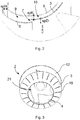
- FIGS. 1 and 2 is a side sectional view of a fan assembly 1 in a first embodiment with detail views A and B and an enlarged view ( Fig. 2 ) of the detail.
- the blower arrangement 1 comprises a (radial) impeller 2, formed from a flat bottom disk 12, a funnel-shaped cover disk 3 and a blade ring formed therebetween and formed of a plurality of impeller blades 4.
- the cover disk 3 of the impeller 2 covers the impeller blades 4 and has an axial intake opening 21 and a radial exhaust section.
- the blower arrangement 1 Upstream of the impeller 2 in the flow direction, the blower arrangement 1 comprises a suction nozzle 6, which extends in sections into the intake opening 21 of the impeller 2 in the overlapping section 5.
- the outer diameter of the suction nozzle 6 is less in the overlapping portion 5 than that of the suction port 21 of the impeller 2, so that between the suction nozzle 6 and the cover plate 3 of the impeller 2, a circumferential nozzle gap 7 is formed.
- the impeller 2 and the suction nozzle 6 are enclosed radially on the outside by an outer nozzle 8 in the circumferential direction, wherein between the outer nozzle 8 and the suction nozzle 6, a circumferential radial gap is provided which forms the running in the direction of flow inlet nozzle channel 9, and between the outer nozzle 8 and the cover plate 3 of the impeller 2, a circumferential radial gap is provided which forms the gap channel 10 extending in the flow direction.
- the suction nozzle 6 protrudes in the axial direction beyond the suction-side axial end of the outer nozzle 8 and extends in its free axial end portion 16 radially outwardly curved, so that between the suction nozzle 6 and the outer nozzle 8 is formed a radially outwardly facing inlet opening 19.
- the geometric shape of the outer nozzle 8 and the suction nozzle 6 is identical in the region of the inlet opening 19, so that both elements run parallel to one another and form the inlet nozzle channel 9 with an essentially constant gap dimension spN.
- the free, extending into the suction port 21 of the impeller 2 in End portion of the suction nozzle 6 is formed so that it tapers radially outwards onto the cover disk 3 of the impeller 2 so that the radial nozzle gap dimension spD of the nozzle gap 7 in the axial flow direction is reduced in the overlapping section 5 between the suction nozzle 6 and the impeller 2.
- the flow is directed against the inner wall of the cover plate 3.
- the geometric shape is implemented by a rounding of the suction nozzle 6 and an axial section of the cover disk 3 which extends parallel to the axis of rotation of the impeller 2 and adjoins the suction opening 21.
- the inlet channel 9 terminates at the axial end of the cover plate 3, i. the inlet opening 21.
- the cover plate 3 divides the inlet channel 9 substantially centrally in a downstream in the flow direction splitting channel 10 between the cover plate 3 of the impeller 2 and the outer nozzle 8, which has a substantially constant gap spK. This is achieved by a substantially identical geometric shape of outer nozzle 8 and cover disk 3 in the region of the cover disk 3.
- the outer nozzle 8 has on the pressure side over the impeller 2 also extended Strömungsleitgeometrie 11 which extends in the radial and axial direction on the adjacent to the cover plate 3 of the impeller 2 exhaust opening of the impeller 2 out and blown out of the impeller 2 flow in the axial Direction heads.
- the outer nozzle 8 is shaped in such a way that its throughflow cross-section, viewed in the direction of flow, is reduced from an initial cross-section to a minimum cross-section and then increased initially to the region of the cover disk 3 and beyond in the region of the flow-guide geometry 11.
- the nozzle gap 7 between the suction nozzle 6 and the cover disk 3 of the impeller 2 is in the region of the minimum cross-section, i. arranged in the region of maximum negative pressure.
- the total volume flow generated via the impeller 2 is suction side of the suction nozzle 6 and the outer nozzle 8 in divided by the suction nozzle 6 into the suction port 21 of the impeller 2 flowing main volume flow HV and flowing through the inlet nozzle channel 9 secondary volume flow NV.
- the secondary volume flow NV is then divided by the cover plate 3 of the impeller 2 and the outer nozzle 8 into the gap volume flow SV flowing through the gap channel 10 and the auxiliary volume flow HiV flowing into the nozzle gap 7 as a pulse flow to the main volume flow HV.
- all streams are brought together again.
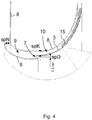
- FIG. 3 is one for the execution according to FIG. 1 usable, designed as a radial impeller impeller 2 is shown in a perspective view.
- the gap blades 15 are uniformly distributed in the circumferential direction over the cover plate 3 and extend at a distance to and between the edge portions of the suction port 21 and the blow-out between the bottom plate 12 and cover plate third
- FIG. 4 is an alternative embodiment of the fan assembly 1 of the FIGS. 1 and 2 shown.
- impeller 2 used with splitter blades 15 which protrude into the gap channel 10 in the direction of the outer nozzle 8.
- the radial extent of the gap vanes 15 corresponds to 50% of the gap dimension spK of the gap channel 10.
- an alternative outer nozzle 8 is used, the suction side extended in a straight line in the radial direction and pressure side is formed without Strömungsleitgeometrie.
- the intake opening gap dimension spN is greater than the gap channel dimension spK of the gap channel 10 and is larger than the nozzle gap dimension spD of the nozzle gap 7.
- the ratios of the minimum and maximum intake flow cross-sections DHmin, DHmax to the maximum impeller outer diameter DA of the impeller 2 are set to 0.3 ⁇ DHmin / DA ⁇ 0.9 and DHmin / DA ⁇ DHmax / DA ⁇ 1.
- the ratio between the nozzle gap dimension spD of the nozzle gap 7 and the impeller outer diameter DA is 0.005.
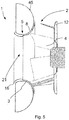
- FIG. 5 is a side sectional view of the fan assembly 1 is shown in an embodiment in which the outer nozzle 8 forms a diffuser 45.
- the diffuser 45 forms an extension of the nozzle contour at the impeller outlet of the impeller 2 in order to reduce Carnot losses.
- the nozzle contour is formed in accordance with the contour of the cover disk 3 of the impeller 3, so that the gap channel 10 has a substantially constant flow cross-sectional area.
- split vanes 15 can be used, as described above.
Landscapes
- Engineering & Computer Science (AREA)
- Mechanical Engineering (AREA)
- General Engineering & Computer Science (AREA)
- Structures Of Non-Positive Displacement Pumps (AREA)
- Jet Pumps And Other Pumps (AREA)
Abstract
Description
- Die Erfindung betrifft eine Gebläseanordnung mit einem Laufrad, einer dem Laufrad in Strömungsrichtung vorgeschalteten Ansaugdüse und einer Außendüse, die zu dem Laufrad und der Ansaugdüse in radialer Richtung beabstandet und diese in Umfangsrichtung umschließend angeordnet ist.
- Die zugrundeliegende technische Aufgabe einer Düsenanordnung an einem Gebläse besteht darin, das zu fördernde Fluid möglichst verlustfrei zuzuführen. Dabei wird zwischen dem Hauptvolumenstrom und dem Rezirkulisationsvolumenstrom unterschieden. Der Hauptvolumenstrom stellt den eigentlich geförderten Volumenstrom dar und wird von der Ansaugseite durch das Laufrad zur Druckseite befördert. Der Rezirkulisationsvolumenstrom ist eine Rückströmung, die von der Druckseite her kommend durch den Spalt zwischen Laufrad und Düse wieder auf der Saugseite in das Laufrad des Gebläses eintritt. Dies entspricht einem Impulsstrom durch den Spalt zwischen Laufrad und Düse der zur Umlenkung der Strömung im Bereich der Deckscheibe sehr vorteilhaft ist. Gleichzeitig ist jedoch nachteilig, dass dieser Rezirkulisationsvolumenstrom einen volumetrischen Verlust darstellt.
- Der Erfindung liegt deshalb die Aufgabe zugrunde, eine Gebläseanordnung mit Düse bereitzustellen, welche die Vorteile des Impulsstroms zwischen Laufrad und Düse nutzt, ohne einen volumetrischen Verlust durch einen Rezirkulisationsvolumenstrom hinnehmen zu müssen. Dabei soll der Hauptvolumenstrom dem Laufrad des Gebläses weiterhin soweit als möglich verlustfrei zugeführt werden.
- Diese Aufgabe wird durch die Merkmalskombination gemäß Patentanspruch 1 gelöst.
- Erfindungsgemäß wird hierfür eine Gebläseanordnung mit einem Laufrad mit einer axialen Ansaugöffnung, die von einer Laufradschaufeln zumindest abschnittsweise überdeckenden Deckscheibe gebildet ist, einer dem Laufrad in Strömungsrichtung vorgeschalteten Ansaugdüse, die sich in die Ansaugöffnung des Laufrads zumindest abschnittsweise in einem Überlappungsabschnitt hinein erstreckt, wobei zwischen der Ansaugdüse und der Deckscheibe des Laufrads ein umlaufender Düsenspalt gebildet ist, und einer Außendüse, die zu dem Laufrad und der Ansaugdüse in radialer Richtung beabstandet und diese in Umfangsrichtung umschließend angeordnet ist, vorgeschlagen. Zwischen der Außendüse und der Ansaugdüse ist ein umlaufender Radialspalt vorgesehen, der einen in Strömungsrichtung verlaufenden Einlaufdüsenkanal bildet. Zwischen der Außendüse und der Deckscheibe des Laufrads ist ebenfalls ein umlaufender Radialspalt vorgesehen, der einen in Strömungsrichtung verlaufenden Spaltkanal bildet, so dass ein von dem Laufrad angesaugter Gesamtvolumenstrom von der Ansaugdüse und der Außendüse in einen durch die Ansaugdüse in das Laufrad strömenden Hauptvolumenstrom und einen durch den Einlaufdüsenkanal strömenden Nebenvolumenstrom aufteilbar ist und der Nebenvolumenstrom anschließend von der Deckscheibe des Laufrads und der Außendüse in einen durch den Spaltkanal strömenden Spaltvolumenstrom und einen in den Düsenspalt zu dem Hauptvolumenstrom einströmenden Hilfsvolumenstrom aufteilbar ist. Die Ansaugdüse bietet mithin eine zweifache Aufteilung sowohl im Ansaugbereich als auch im Überlappungsbereich mit dem Laufrad und fungiert somit als Strömungsteilungsdüse.
- Die erfindungsgemäße Gebläseanordnung bewirkt eine Wirkungsgradsteigerung bei Laufrädern, insbesondere bei Radiallaufrädern infolge der Vermeidung bzw. Verringerung des Rezirkulisationsvolumenstroms bei gleichzeitiger Aufrechterhaltung des vorteilhaften Impulsstromes im Düsenspalt zwischen Laufrad und Ansaugdüse.
- Bei der Gebläseanordnung ist vorgesehen, dass der Gesamtvolumenstrom gebildet ist aus der Summe des von der Ansaugdüse und der Außendüse in den durch die Ansaugdüse in das Laufrad strömenden Hauptvolumenstroms und des durch den Einlaufdüsenkanal strömenden Nebenvolumenstroms.
- Der Nebenvolumenstrom ist wiederum gebildet aus der Summe des durch den Spaltkanal strömenden Spaltvolumenstroms und des in den Düsenspalt zu dem Hauptvolumenstrom einströmenden Hilfsvolumenstroms.
- Eine vorteilhafte Ausführungsvariante der Gebläseanordnung sieht vor, dass sich die Ansaugdüse in axialer Richtung über ein ansaugseitiges axiales Ende der Außendüse hinaus und in ihrem freien axialen Endabschnitt nach radial außen gekrümmt erstreckt, so dass zwischen der Ansaugdüse und der Außendüse eine nach radial außen weisende Einlassöffnung gebildet ist. Die Ansaugung zwischen der Außendüse und der Ansaugdüse in den Einlaufdüsenkanal erfolgt somit nicht in axialer, sondern in radialer Richtung, wohingegen die Hauptströmung durch die gesamte Ansaugdüse hauptsächlich in axialer Richtung verläuft.
- Das Zusammenwirken zwischen Ansaugdüse und Laufrad, insbesondere Radiallaufrad, sieht in einer Ausführungsvariante vor, dass der freie Endabschnitt der Ansaugdüse, der sich in die Ansaugöffnung des Laufrads hinein erstreckt, auf die Deckscheibe des Laufrads nach radial außen zuläuft, so dass sich im Überlappungsabschnitt zwischen Ansaugdüse und Laufrad ein radiales Düsenspaltmaß des Düsenspalts in axialer Strömungsrichtung gesehen verringert. Die Strömung wird somit im Düsenspalt gegen die Deckscheibe des Laufrads gelenkt.
- Dabei ist eine Ausführung günstig, bei der die Deckscheibe an ihrem an die Ansaugöffnung angrenzenden Axialabschnitt parallel zur Rotationsachse des Laufrads verläuft. Dadurch ist der Verlauf im Überlappungsabschnitt ebenfalls parallel zur Rotationsachse des Laufrads. Im weiteren axialen Verlauf vergrößert sich der Durchströmungsquerschnitt des Laufrads entlang der Deckscheibe in Strömungsrichtung, wobei sich die Deckscheibe entsprechend in radialer Richtung aufweitet.
- Ferner ist eine Ausführung der Gebläseanordnung strömungstechnisch vorteilhaft, bei der ein Spaltkanalmaß spK des Spaltkanals zwischen der Außendüse und der Deckscheibe des Laufrads in axialer Strömungsrichtung im Wesentlichen konstant ist. Der geometrische Verlauf von Außendüse und Deckscheibe sind mithin identisch oder im Wesentlichen identisch.
- Zudem ist strömungstechnisch vorteilhaft, wenn das Einlaufdüsenkanalspaltmaß spN des Einlaufdüsenspaltkanals in axialer Strömungsrichtung von der Einlauföffnung bis zu der Deckscheibe des Laufrads konstant oder im Wesentlichen konstant ist.
- In einer Weiterbildung der Gebläseanordnung ist vorgesehen, dass die Außendüse druckseitig eine über das Laufrad hinaus verlängerte Strömungsleitgeometrie aufweist, die sich in radialer Richtung über eine an der Deckscheibe des Laufrads angrenzenden Ausblasöffnung des Laufrads hinaus erstreckt und ausgebildet ist, die von dem Laufrad ausgeblasene Strömung in eine vorbestimmte Richtung zu leiten. Alternativ oder zusätzlich kann in einer Ausführung der Gebläseanordnung ferner vorgesehen werden, dass die Außendüse druckseitig eine über das Laufrad hinaus verlängerte Strömungsleitgeometrie aufweist, die eine an der Deckscheibe des Laufrads angrenzende Ausblasöffnung des Laufrads in axialer Richtung überspannt und ausgebildet ist, die von dem Laufrad ausgeblasene Strömung in eine vorbestimmte Richtung zu leiten. Die Strömungsleitgeometrie kann dabei auch dazu genutzt werden, die Strömungsrichtung umzulenken. Bei einem Radiallaufrad beispielsweise aus einer radialen in eine axiale Richtung. Dies führt bei einer Verwendung der Gebläseanordnung beispielsweise in einem Rohr oder in einem Kasten, wo eine axiale Strömung erreicht werden soll, zu einer erheblichen Wirkungsgradsteigerung. Zudem sind Zusatzbauteile zur Ausrichtung der Strömung obsolet.
- Ein weiteres Ausführungsbeispiel der Gebläseanordnung sieht vor, dass auf der Deckscheibe des Laufrads in Richtung der Außendüse hervorstehende Spaltschaufeln vorgesehen sind. Dabei ist vorteilhaft, dass die Spaltschaufeln eine Verbesserung des Wirkungsgrades gewährleisten, indem sie im Betrieb des Laufrads gegen die Druckdifferenz von Druckseite und Saugseite der Gebläseanordnung bzw. von einem Bereich der Ansaugdüse und einem Ausblasabschnitt am Laufrad arbeiten.
- Die Spaltschaufeln sind in vorteilhaften Ausführungsbeispielen als geradlinige Radialschaufeln oder vorwärts- oder rückwärtsgekrümmte Schaufeln ausgebildet. Ihre Höhenerstreckung in den Spaltkanal liegt in einem Bereich von 40-60% der Maximalhöhe des Spaltkanals abzüglich der Fertigungstoleranz.
- Ferner ist günstig, wenn die Spaltschaufeln gegenüber der Ansaugöffnung des Laufrads in axialer Strömungsrichtung beabstandet angeordnet sind. Ihre bevorzugte Erstreckung in Strömungsrichtung entspricht 40-90%, insbesondere 40-70% der axialen Projektionslänge der Deckscheibe des Laufrads. Zudem werden die Spaltschaufeln in gleichmäßigen Abständen über den gesamten Umfang der Deckscheibe verteilt angeordnet. Die Anzahl der Spaltschaufeln ist in einer vorteilhaften Ausführung größer als 12, weiter bevorzugt größer als 16, noch weiter bevorzugt größer als 20.
- Bezüglich der Geometrie der Außendüse ist vorteilhafterweise vorgesehen, dass sich ihr Durchströmungsquerschnitt in Strömungsrichtung gesehen von einem Anfangsquerschnitt auf einen Minimalquerschnitt verringert und anschließend auf einen Endquerschnitt vergrößert. Der Düsenspalt ist vorzugsweise zwischen der Ansaugdüse und der Deckscheibe des Laufrads in einem Bereich des Minimalquerschnitts angeordnet, in dem der Druck minimal und die Strömungsgeschwindigkeit maximal sind.
- Zur Erreichung eines hohen Wirkungsgrades wird bei der Gebläseanordnung das Verhältnis zwischen dem Düsenspaltmaß spD des Düsenspalts und dem Laufradaußendurchmesser DA des Laufrads möglichst klein festgelegt und liegt in einem Bereich von 0,003 bis 0,007 oder bei 0,005.
- Ferner wird in einer strömungstechnisch günstigen Ausführungsvariante der Gebläseanordnung vorgesehen, dass das Ansaugöffnungsspaltmaß spN größer als das Spaltkanalmaß spK des Spaltkanals und größer als das Düsenspaltmaß spD des Düsenspalts ist. Der zehnfache Wert ist jedoch nicht zu überschreiten, so dass gilt spN ≤ 10*spK, SpD.
- Auch ist eine Ausführung strömungstechnisch vorteilhaft, bei der sich der Durchströmungsquerschnitt DH der Ansaugdüse in Strömungsrichtung von einem maximalen Ansaugdurchströmungsquerschnitt DHmax auf einen minimalen Durchströmungsquerschnitt DHmin verringert, wobei ein Verhältnis des minimalen und maximalen Ansaugdurchströmungsquerschnitts DHmin, DHmax zu einem Laufradaußendurchmesser DA des Laufrads in einem Bereich liegt, dass gilt DHmin/DA < DHmax/DA < 1. Zudem liegt ein vorteilhaftes Verhältnis des minimalen Ansaugdurchströmungsquerschnitts DHmin zu dem Laufradaußendurchmesser DA des Laufrads in einem Bereich, dass gilt 0,3 < DHmin/DA < 0,9.
- Andere vorteilhafte Weiterbildungen der Erfindung sind in den Unteransprüchen gekennzeichnet bzw. werden nachstehend zusammen mit der Beschreibung der bevorzugten Ausführung der Erfindung anhand der Figuren näher dargestellt. Alle offenbarten Merkmale sind beliebig kombinierbar soweit dies technisch möglich und nicht widersprüchlich ist. Es zeigen:
- Fig. 1
- eine seitliche Schnittansicht der Gebläseanordnung in einem ersten Ausführungsbeispiel mit Detailansichten A und B;
- Fig. 2
- eine vergrößerte Ansicht der Detailansichten A, B aus
Figur 1 ; - Fig. 3
- eine perspektivische Ansicht eines Laufrads in einer alternativen Ausführungsform;
- Fig. 4
- eine seitliche Schnittansicht einer Gebläseanordnung in einem weiteren Ausführungsbeispiel;
- Fig. 5
- eine seitliche Schnittansicht der Gebläseanordnung in einem weiteren Ausführungsbeispiel.
- Gleiche Bezugszeichen benennen gleiche Teile in allen Ansichten.
- In den
Figuren 1 und2 ist eine seitliche Schnittansicht einer Gebläseanordnung 1 in einem ersten Ausführungsbeispiel mit Detailansichten A und B sowie einer vergrößerten Ansicht (Fig. 2 ) des Details gezeigt. Die Gebläseanordnung 1 umfasst ein (Radial-)Laufrad 2, gebildet aus einer ebenen Bodenscheibe 12, einer trichterförmigen Deckscheibe 3 sowie einem dazwischen angeordneten, aus mehreren Laufradschaufeln 4 gebildeten Schaufelkranz. Die Deckscheibe 3 des Laufrads 2 überdeckt die Laufradschaufeln 4 und weist eine axiale Ansaugöffnung 21 sowie einen radialen Ausblasabschnitt auf. Dem Laufrad 2 in Strömungsrichtung vorgeschaltet umfasst die Gebläseanordnung 1 eine Ansaugdüse 6, die sich in die Ansaugöffnung 21 des Laufrads 2 abschnittsweise im Überlappungsabschnitt 5 hinein erstreckt. Der Außendurchmesser der Ansaugdüse 6 ist im Überlappungsabschnitt 5 geringer als derjenige der Ansaugöffnung 21 des Laufrads 2, so dass zwischen der Ansaugdüse 6 und der Deckscheibe 3 des Laufrads 2 ein umlaufender Düsenspalt 7 gebildet ist. Das Laufrad 2 und die Ansaugdüse 6 werden radial außenseitig von einer Außendüse 8 in Umfangsrichtung umschlossen, wobei zwischen der Außendüse 8 und der Ansaugdüse 6 ein umlaufender Radialspalt vorgesehen ist, der den in Strömungsrichtung verlaufenden Einlaufdüsenkanal 9 bildet, und zwischen der Außendüse 8 und der Deckscheibe 3 des Laufrads 2 ein umlaufender Radialspalt vorgesehen ist, der den in Strömungsrichtung verlaufenden Spaltkanal 10 bildet. - Die Ansaugdüse 6 steht in axialer Richtung über das ansaugseitige axiale Ende der Außendüse 8 hervor und erstreckt sich in ihrem freien axialen Endabschnitt 16 nach radial außen gekrümmt, so dass zwischen der Ansaugdüse 6 und der Außendüse 8 eine nach radial außen weisende Einlassöffnung 19 gebildet ist. Die geometrische Form der Außendüse 8 und der Ansaugdüse 6 ist im Bereich der Einlassöffnung 19 identisch, so dass beide Elemente parallel zueinander verlaufen und den Einlaufdüsenkanal 9 mit im Wesentlichen konstanten Spaltmaß spN bilden.
- Der freie, sich in die Ansaugöffnung 21 des Laufrads 2 hinein erstreckende Endabschnitt der Ansaugdüse 6 ist so ausgebildet, dass er auf die Deckscheibe 3 des Laufrads 2 nach radial außen zuläuft, so dass sich im Überlappungsabschnitt 5 zwischen Ansaugdüse 6 und Laufrad 2 das radiale Düsenspaltmaß spD des Düsenspalts 7 in axialer Strömungsrichtung gesehen verringert. Zudem wird die Strömung gegen die Innenwand der Deckscheibe 3 geleitet. Umgesetzt ist die geometrische Form durch eine Rundung der Ansaugdüse 6 und einem parallel zur Rotationsachse des Laufrads 2 verlaufenden, an die Ansaugöffnung 21 angrenzenden Axialabschnitt der Deckscheibe 3.
- Der Einlaufkanal 9 endet an dem axialen Ende der Deckscheibe 3, d.h. der Ansaugöffnung 21. Die Deckscheibe 3 teilt den Einlaufkanal 9 im Wesentlichen mittig in einen sich in Strömungsrichtung anschließenden Spaltkanal 10 zwischen der Deckscheibe 3 des Laufrads 2 und der Außendüse 8, der ein im Wesentlichen konstantes Spaltmaß spK aufweist. Dies wird durch eine im Wesentlichen identische geometrische Form von Außendüse 8 und Deckscheibe 3 im Bereich der Deckscheibe 3 erreicht. Die Außendüse 8 weist druckseitig eine über das Laufrad 2 hinaus verlängerte Strömungsleitgeometrie 11 auf, die sich in radialer und axialer Richtung über die an der Deckscheibe 3 des Laufrads 2 angrenzenden Ausblasöffnung des Laufrads 2 hinaus erstreckt und die von dem Laufrad 2 ausgeblasene Strömung in die axiale Richtung leitet. Die Außendüse 8 ist so geformt, dass sich ihr Durchströmungsquerschnitt in Strömungsrichtung gesehen von einem Anfangsquerschnitt auf einen Minimalquerschnitt verringert und anschließend zunächst bis zum Bereich der Deckscheibe 3 sowie darüber hinaus im Bereich der Strömungsleitgeometrie 11 vergrößert. Der Düsenspalt 7 zwischen der Ansaugdüse 6 und der Deckscheibe 3 des Laufrads 2 ist im Bereich des Minimalquerschnitts, d.h. im Bereich des maximalen Unterdrucks angeordnet.
- Bei der Gebläseanordnung 1 wird der über das Laufrad 2 erzeugte Gesamtvolumenstrom ansaugseitig von der Ansaugdüse 6 und der Außendüse 8 in den durch die Ansaugdüse 6 in die Ansaugöffnung 21 des Laufrads 2 strömenden Hauptvolumenstrom HV und den durch den Einlaufdüsenkanal 9 strömenden Nebenvolumenstrom NV aufgeteilt. Der Nebenvolumenstrom NV wird anschließend von der Deckscheibe 3 des Laufrads 2 und der Außendüse 8 in den durch den Spaltkanal 10 strömenden Spaltvolumenstrom SV und den in den Düsenspalt 7 als Impulsstrom zu dem Hauptvolumenstrom HV einströmenden Hilfsvolumenstrom HiV aufgeteilt. Im radialen Ausblasabschnitt des Laufrads 2 sind alle Ströme wieder zusammengeführt.
- In
Figur 3 ist ein für die Ausführung gemäßFigur 1 einsetzbares, als Radiallaufrad ausgebildetes Laufrad 2 in einer perspektivischen Ansicht dargestellt. Bei der Ausführung gemäßFigur 3 ist jedoch im Gegensatz zur Ausführung gemäßFigur 1 auf der Deckscheibe 3 eine Vielzahl von als Radialschaufeln ausgebildete Spaltschaufeln 15 angeordnet. Die Spaltschaufeln 15 sind gleichmäßig in Umfangsrichtung über die Deckscheibe 3 verteilt und erstrecken sich beabstandet zu und zwischen den Randabschnitten der Ansaugöffnung 21 und des Ausblasabschnitts zwischen Bodenscheibe 12 und Deckscheibe 3. - In
Figur 4 ist eine alternative Ausführung der Gebläseanordnung 1 aus denFiguren 1 und2 dargestellt. Zur Vermeidung von Wiederholungen gilt die obige Offenbarung zu denFiguren 1 und2 auch fürFigur 4 . Im Unterschied zur Ausführung gemäßFigur 1 ist das inFigur 3 gezeigte Laufrad 2 mit Spaltschaufeln 15 verwendet, die in den Spaltkanal 10 in Richtung der Außendüse 8 hervorstehen. Die radiale Erstreckung der Spaltschaufeln 15 entspricht 50% des Spaltmaßes spK des Spaltkanals 10. Zudem ist eine alternative Außendüse 8 verwendet, die ansaugseitig in radialer Richtung geradlinig verlängert und druckseitig ohne Strömungsleitgeometrie ausgebildet ist. - Für alle offenbarten Ausführungsbeispiele gilt, dass das Ansaugöffnungsspaltmaß spN größer als das Spaltkanalmaß spK des Spaltkanals 10 und größer als das Düsenspaltmaß spD des Düsenspalts 7 ist. In den Ausführungen gemäß
Figur 2 undFigur 4 gilt spN = 1,5*spK und spN = 2,5*SpD. - Ferner sind die Verhältnisse des minimalen und maximalen Ansaugdurchströmungsquerschnitts DHmin, DHmax zu dem maximalen Laufradaußendurchmesser DA des Laufrads 2 festgelegt auf 0,3<DHmin/DA < 0,9 und DHmin/DA <DHmax/DA ≤ 1.
- Das Verhältnis zwischen dem Düsenspaltmaß spD des Düsenspalts 7 und dem Laufradaußendurchmesser DA liegt bei 0,005.
- In
Figur 5 ist eine seitliche Schnittansicht der Gebläseanordnung 1 in einem Ausführungsbeispiel dargestellt, bei dem die Außendüse 8 einen Diffusor 45 bildet. Im Übrigen geltenden die Merkmale der vorigen Ausführungsbeispiele vollumfänglich auch für das Ausführungsbeispiel gemäßFig. 5 . Der Diffusor 45 bildet eine Verlängerung der Düsenkontur am Laufradaustritt des Laufrads 2, um die Carnot-Verluste zu verringern. Die Düsenkontur ist entsprechend der Kontur der Deckscheibe 3 des Laufrads 3 ausgebildet, so dass der Spaltkanal 10 eine im Wesentlichen konstante Durchströmungsquerschnittsfläche aufweist. Auch in dieser Ausführung können Spaltschaufeln 15 eingesetzt werden, wie vorstehend beschrieben.
Claims (20)
- Gebläseanordnung (1) mita. einem Laufrad (2), das eine axiale Ansaugöffnung (21) aufweist, die von einer Laufradschaufeln (4) zumindest abschnittsweise überdeckenden Deckscheibe (3) gebildet ist,b. einer dem Laufrad (2) in Strömungsrichtung vorgeschalteten Ansaugdüse (6), die sich in die Ansaugöffnung des Laufrads (2) zumindest abschnittsweise in einem Überlappungsabschnitt (5) hinein erstreckt, wobei zwischen der Ansaugdüse (6) und der Deckscheibe (3) des Laufrads (2) ein umlaufender Düsenspalt (7) gebildet ist,c. einer Außendüse (8), die zu dem Laufrad (2) und der Ansaugdüse (6) in radialer Richtung beabstandet und diese in Umfangsrichtung umschließend angeordnet ist,i. wobei zwischen der Außendüse (8) und der Ansaugdüse (6) ein umlaufender Radialspalt vorgesehen ist, der einen in Strömungsrichtung verlaufenden Einlaufdüsenkanal (9) bildet, und wobei zwischen der Außendüse (8) und der Deckscheibe (3) des Laufrads (2) ein umlaufender Radialspalt vorgesehen ist, der einen in Strömungsrichtung verlaufenden Spaltkanal (10) bildet,ii. so dass ein von dem Laufrad (2) angesaugter Gesamtvolumenstrom von der Ansaugdüse (6) und der Außendüse (8) in einen durch die Ansaugdüse (6) in das Laufrad (2) strömenden Hauptvolumenstrom und einen durch den Einlaufdüsenkanal (9) strömenden Nebenvolumenstrom aufteilbar ist und der Nebenvolumenstrom anschließend von der Deckscheibe (3) des Laufrads (2) und der Außendüse (8) in einen durch den Spaltkanal (10) strömenden Spaltvolumenstrom und einen in den Düsenspalt (7) zu dem Hauptvolumenstrom einströmenden Hilfsvolumenstrom aufteilbar ist.
- Gebläseanordnung nach Anspruch 1, dadurch gekennzeichnet, dass sich die Ansaugdüse (6) in axialer Richtung über ein ansaugseitiges axiales Ende der Außendüse (8) hinaus und in ihrem freien axialen Endabschnitt (16) nach radial außen gekrümmt erstreckt, wobei zwischen der Ansaugdüse (6) und der Außendüse (8) eine nach radial außen weisende Einlassöffnung gebildet ist.
- Gebläseanordnung nach Anspruch 1 oder 2, dadurch gekennzeichnet, dass ein freier Endabschnitt der Ansaugdüse (6), der sich in die Ansaugöffnung des Laufrads (2) hinein erstreckt, auf die Deckscheibe (3) des Laufrads (2) nach radial außen zuläuft, wobei sich im Überlappungsabschnitt (5) zwischen Ansaugdüse (6) und Laufrad (2) ein radiales Düsenspaltmaß spD des Düsenspalts in axialer Strömungsrichtung gesehen verringert.
- Gebläseanordnung nach einem der vorigen Ansprüche, dadurch gekennzeichnet, dass die Deckscheibe (3) an ihrem an die Ansaugöffnung angrenzenden Axialabschnitt parallel zur Rotationsachse des Laufrads (2) verläuft.
- Gebläseanordnung nach einem der vorigen Ansprüche, dadurch gekennzeichnet, dass ein Spaltkanalmaß spK des Spaltkanals (10) in axialer Strömungsrichtung konstant ist.
- Gebläseanordnung nach einem der vorigen Ansprüche, dadurch gekennzeichnet, dass ein Einlaufdüsenkanalspaltmaß spN des Einlaufdüsenspaltkanals (9) in axialer Strömungsrichtung von der Einlauföffnung (19) bis zu der Deckscheibe (3) des Laufrads (2) konstant ist.
- Gebläseanordnung nach einem der vorigen Ansprüche, dadurch gekennzeichnet, dass die Außendüse (8) druckseitig eine über das Laufrad (2) hinaus verlängerte Strömungsleitgeometrie (11) aufweist, die sich in radialer Richtung über eine an der Deckscheibe (3) des Laufrads (2) angrenzenden Ausblasöffnung des Laufrads (2) hinaus erstreckt und ausgebildet ist, die von dem Laufrad (2) ausgeblasene Strömung zu leiten.
- Gebläseanordnung nach einem der vorigen Ansprüche, dadurch gekennzeichnet, dass die Außendüse (8) druckseitig eine über das Laufrad (2) hinaus verlängerte Strömungsleitgeometrie (11) aufweist, die eine an der Deckscheibe (3) des Laufrads (2) angrenzende Ausblasöffnung des Laufrads (2) in axialer Richtung überspannt und ausgebildet ist, die von dem Laufrad (2) ausgeblasene Strömung zu leiten.
- Gebläseanordnung nach einem der vorigen Ansprüche, dadurch gekennzeichnet, dass auf der Deckscheibe (3) des Laufrads (2) in Richtung der Außendüse (8) hervorstehende Spaltschaufeln (15) vorgesehen sind.
- Gebläseanordnung nach dem vorigen Anspruch, dadurch gekennzeichnet, dass die Spaltschaufeln (15) als geradlinige Radialschaufeln oder rückwärtsgekrümmte Schaufeln ausgebildet sind.
- Gebläseanordnung nach einem der vorigen Ansprüche 9 - 10, dadurch gekennzeichnet, dass die Spaltschaufeln (15) gegenüber der Ansaugöffnung des Laufrads (2) in axialer Strömungsrichtung beabstandet angeordnet sind.
- Gebläseanordnung nach einem der vorigen Ansprüche, dadurch gekennzeichnet, dass sich ein Durchströmungsquerschnitt der Außendüse (8) in Strömungsrichtung gesehen von einem Anfangsquerschnitt auf einen Minimalquerschnitt verringert und anschließend auf einen Endquerschnitt vergrößert, wobei der Düsenspalt (7) zwischen der Ansaugdüse (6) und der Deckscheibe (3) des Laufrads (2) in einem Bereich des Minimalquerschnitts angeordnet ist.
- Gebläseanordnung nach einem der vorigen Ansprüche 3 bis 12, dadurch gekennzeichnet, dass ein Verhältnis spD/DA zwischen dem Düsenspaltmaß spD des Düsenspalts und einem Laufradaußendurchmesser DA des Laufrads (2) in einem Bereich von 0,003 bis 0,003 oder bei 0,005 liegt.
- Gebläseanordnung nach einem der vorigen Ansprüche 6 - 13, dadurch gekennzeichnet, dass das Ansaugöffnungsspaltmaß spN größer als das Spaltkanalmaß spK des Spaltkanals und größer als das Düsenspaltmaß spD des Düsenspalts ist, wobei gilt spN ≤ 10*spK, SpD.
- Gebläseanordnung nach einem der vorigen Ansprüche, dadurch gekennzeichnet, dass sich ein Durchströmungsquerschnitt DH der Ansaugdüse (6) in Strömungsrichtung von einem maximalen Ansaugdurchströmungsquerschnitt DHmax auf einen minimalen Durchströmungsquerschnitt DHmin verringert, wobei ein Verhältnis des minimalen und maximalen Ansaugdurchströmungsquerschnitts DHmin, DHmax zu einem Laufradaußendurchmesser DA des Laufrads (2) in einem Bereich liegt, dass gilt DHmin/DA < DHmax/DA < 1.
- Gebläseanordnung nach einem der vorigen Ansprüche, dadurch gekennzeichnet, dass sich ein Durchströmungsquerschnitt DH der Ansaugdüse (6) in Strömungsrichtung von einem maximalen Ansaugdurchströmungsquerschnitt DHmax auf einen minimalen Durchströmungsquerschnitt DHmin verringert, wobei ein Verhältnis des minimalen Ansaugdurchströmungsquerschnitts DHmin zu einem Laufradaußendurchmesser DA des Laufrads (2) in einem Bereich liegt, dass gilt 0,3 < DHmin/DA < 0,9.
- Gebläseanordnung nach einem der vorigen Ansprüche, dadurch gekennzeichnet, dass sich ein Durchströmungsquerschnitt des Laufrads (2) entlang der Deckscheibe (3) in Strömungsrichtung vergrößert.
- Gebläseanordnung nach einem der vorigen Ansprüche, dadurch gekennzeichnet, dass der Gesamtvolumenstrom gebildet ist aus der Summe des von der Ansaugdüse (6) und der Außendüse (8) in den durch die Ansaugdüse (6) in das Laufrad (2) strömenden Hauptvolumenstroms und des durch den Einlaufdüsenkanal strömenden Nebenvolumenstroms.
- Gebläseanordnung nach einem der vorigen Ansprüche, dadurch gekennzeichnet, dass der Nebenvolumenstrom gebildet ist aus der Summe des durch den Spaltkanal strömenden Spaltvolumenstroms und des in den Düsenspalt (7) zu dem Hauptvolumenstrom einströmenden Hilfsvolumenstroms.
- Gebläseanordnung nach einem der vorigen Ansprüche, dadurch gekennzeichnet, dass die Außendüse (8) einen druckseitig eine über das Laufrad (2) hinaus verlängerten Diffusor (45) bildet.
Applications Claiming Priority (1)
| Application Number | Priority Date | Filing Date | Title |
|---|---|---|---|
| DE102017110642.1A DE102017110642A1 (de) | 2017-05-16 | 2017-05-16 | Gebläseanordnung mit Strömungsteilungsdüse |
Publications (2)
| Publication Number | Publication Date |
|---|---|
| EP3404269A1 true EP3404269A1 (de) | 2018-11-21 |
| EP3404269B1 EP3404269B1 (de) | 2020-09-30 |
Family
ID=61381165
Family Applications (1)
| Application Number | Title | Priority Date | Filing Date |
|---|---|---|---|
| EP18159980.4A Active EP3404269B1 (de) | 2017-05-16 | 2018-03-05 | Gebläseanordnung mit strömungsteilungsdüse |
Country Status (4)
| Country | Link |
|---|---|
| US (1) | US10808719B2 (de) |
| EP (1) | EP3404269B1 (de) |
| CN (1) | CN206957995U (de) |
| DE (1) | DE102017110642A1 (de) |
Families Citing this family (7)
| Publication number | Priority date | Publication date | Assignee | Title |
|---|---|---|---|---|
| DE202019100240U1 (de) | 2019-01-16 | 2019-03-06 | Ebm-Papst Mulfingen Gmbh & Co. Kg | Strömungsleitvorrichtung und Gebläseanordnung mit Strömungsleitvorrichtung |
| DE102019101096A1 (de) | 2019-01-16 | 2020-07-16 | Ebm-Papst Mulfingen Gmbh & Co. Kg | Strömungsleitvorrichtung und Gebläseanordnung mit Strömungsleitvorrichtung |
| US11255348B2 (en) * | 2019-03-14 | 2022-02-22 | Regal Beloit America, Inc. | Blower assembly and methods of assembling the same |
| US11761457B2 (en) | 2019-04-16 | 2023-09-19 | Atlas Copco (Wuxi) Compressor Co., Ltd. | Guide device for directing gas through a gas pressurizing device |
| WO2021059899A1 (ja) | 2019-09-27 | 2021-04-01 | 株式会社デンソー | 送風機 |
| DE102021204491A1 (de) | 2021-05-04 | 2022-11-10 | Ziehl-Abegg Se | Ventilator, insbesondere Radial- oder Diagonalventilator |
| CN116658462A (zh) * | 2023-07-15 | 2023-08-29 | 湖南透博工业设计有限公司 | 一种向叶轮进口前端引回流的离心风机 |
Citations (4)
| Publication number | Priority date | Publication date | Assignee | Title |
|---|---|---|---|---|
| US1787656A (en) * | 1929-09-21 | 1931-01-06 | American Blower Corp | Induction flow inlet fan |
| AT241674B (de) * | 1962-10-16 | 1965-08-10 | Theodor Dr Ing Helmbold | Axialgebläse |
| DE4227901A1 (de) * | 1992-08-22 | 1994-02-24 | Behr Gmbh & Co | Lüfteranordnung, insbesondere für die Kühlung von Kraftfahrzeugmotoren |
| DE102013101133A1 (de) * | 2012-02-10 | 2013-08-14 | Visteon Global Technologies Inc. | Gebläsebaugruppe |
Family Cites Families (7)
| Publication number | Priority date | Publication date | Assignee | Title |
|---|---|---|---|---|
| US5525036A (en) * | 1991-11-29 | 1996-06-11 | Goldstar Co., Ltd. | Suction structure of a sirocco fan housing |
| SE515524C2 (sv) * | 1992-10-01 | 2001-08-20 | Flaekt Ab | Inloppsklocka för centrifugalfläktar |
| US5478201A (en) * | 1994-06-13 | 1995-12-26 | Carrier Corporation | Centrifugal fan inlet orifice and impeller assembly |
| DE4431840A1 (de) * | 1994-09-07 | 1996-03-14 | Behr Gmbh & Co | Lüfter für eine Kühlanlage eines Kraftfahrzeugs |
| DE19713712C1 (de) * | 1997-04-03 | 1998-04-16 | Laengerer & Reich Gmbh & Co | Radialventilator, insbesonders als Lüfter für die Kühlanlage eines Kraftfahrzeuges |
| EP1473465B2 (de) * | 2003-04-30 | 2018-08-01 | Holset Engineering Company Limited | Verdichter |
| JP6001707B2 (ja) * | 2015-02-25 | 2016-10-05 | 株式会社オティックス | 過給機用のコンプレッサハウジング |
-
2017
- 2017-05-16 DE DE102017110642.1A patent/DE102017110642A1/de not_active Withdrawn
- 2017-07-18 CN CN201720871134.XU patent/CN206957995U/zh active Active
-
2018
- 2018-03-05 EP EP18159980.4A patent/EP3404269B1/de active Active
- 2018-04-18 US US15/956,272 patent/US10808719B2/en active Active
Patent Citations (4)
| Publication number | Priority date | Publication date | Assignee | Title |
|---|---|---|---|---|
| US1787656A (en) * | 1929-09-21 | 1931-01-06 | American Blower Corp | Induction flow inlet fan |
| AT241674B (de) * | 1962-10-16 | 1965-08-10 | Theodor Dr Ing Helmbold | Axialgebläse |
| DE4227901A1 (de) * | 1992-08-22 | 1994-02-24 | Behr Gmbh & Co | Lüfteranordnung, insbesondere für die Kühlung von Kraftfahrzeugmotoren |
| DE102013101133A1 (de) * | 2012-02-10 | 2013-08-14 | Visteon Global Technologies Inc. | Gebläsebaugruppe |
Also Published As
| Publication number | Publication date |
|---|---|
| CN206957995U (zh) | 2018-02-02 |
| US20180335048A1 (en) | 2018-11-22 |
| DE102017110642A1 (de) | 2018-11-22 |
| EP3404269B1 (de) | 2020-09-30 |
| US10808719B2 (en) | 2020-10-20 |
Similar Documents
| Publication | Publication Date | Title |
|---|---|---|
| EP3404269B1 (de) | Gebläseanordnung mit strömungsteilungsdüse | |
| DE69506297T2 (de) | Axialpumpen | |
| DE102010046870B4 (de) | Seitenkanalgebläse, insbesondere Sekundärluftgebläse für eine Verbrennungskraftmaschine | |
| EP1860325A1 (de) | Diffusor | |
| WO2011054812A2 (de) | Turbomaschine mit axialer verdichtung oder expansion | |
| DE1428191A1 (de) | Kreiselgeblaese | |
| EP3325812B1 (de) | Seitenkanal-maschine (verdichter, vakuumpumpe oder gebläse) mit einem entnahmekanal im abstreifer | |
| EP0916812A1 (de) | Endstufe für axialdurchströmte Turbine | |
| DE102011013841B4 (de) | Radialventilatorrad und Radialventilator | |
| WO2019063384A1 (de) | Diffusor für einen verdichter | |
| EP2194231A1 (de) | Ringdiffusor für eine Axialturbomaschine | |
| DE102009006652B4 (de) | Seitenkanalgebläse, insbesondere Sekundärluftgebläse für eine Verbrennungskraftmaschine | |
| DE102015100215B4 (de) | Seitenkanalgebläse für eine Verbrennungskraftmaschine | |
| WO2019034740A1 (de) | Diffusor für einen radialverdichter | |
| DE202017102950U1 (de) | Gebläseanordnung mit Strömungsteilungsdüse | |
| DE112018000960B4 (de) | Turbinenlaufschaufel und gasturbine | |
| EP3388626A1 (de) | Konturierung einer schaufelgitterplattform | |
| WO2021083442A1 (de) | Turbomaschinen-leitschaufelanordnung | |
| EP3771829A1 (de) | Fördervorrichtung mit einem seitenkanal- oder peripheralgebläse | |
| WO2017194272A1 (de) | Rückführstufe für einen radialturboverdichter und radialturboverdichter | |
| DE1601627C3 (de) | Gekühlte Schaufel fur eine Stromungs maschine | |
| DE102015014900A1 (de) | Radialturbinengehäuse | |
| DE102005012815A1 (de) | Gehäuse, Laufrad und Radialgebläse mit einem Gehäuse und einem Laufrad | |
| DE3439780A1 (de) | Ventilator, insbesondere rohrventilator | |
| EP3114354A1 (de) | Lüfterrad eines axiallüfters |
Legal Events
| Date | Code | Title | Description |
|---|---|---|---|
| PUAI | Public reference made under article 153(3) epc to a published international application that has entered the european phase |
Free format text: ORIGINAL CODE: 0009012 |
|
| STAA | Information on the status of an ep patent application or granted ep patent |
Free format text: STATUS: THE APPLICATION HAS BEEN PUBLISHED |
|
| AK | Designated contracting states |
Kind code of ref document: A1 Designated state(s): AL AT BE BG CH CY CZ DE DK EE ES FI FR GB GR HR HU IE IS IT LI LT LU LV MC MK MT NL NO PL PT RO RS SE SI SK SM TR |
|
| AX | Request for extension of the european patent |
Extension state: BA ME |
|
| STAA | Information on the status of an ep patent application or granted ep patent |
Free format text: STATUS: REQUEST FOR EXAMINATION WAS MADE |
|
| 17P | Request for examination filed |
Effective date: 20190410 |
|
| RBV | Designated contracting states (corrected) |
Designated state(s): AL AT BE BG CH CY CZ DE DK EE ES FI FR GB GR HR HU IE IS IT LI LT LU LV MC MK MT NL NO PL PT RO RS SE SI SK SM TR |
|
| GRAP | Despatch of communication of intention to grant a patent |
Free format text: ORIGINAL CODE: EPIDOSNIGR1 |
|
| STAA | Information on the status of an ep patent application or granted ep patent |
Free format text: STATUS: GRANT OF PATENT IS INTENDED |
|
| RIC1 | Information provided on ipc code assigned before grant |
Ipc: F04D 29/42 20060101ALI20200520BHEP Ipc: F04D 29/16 20060101AFI20200520BHEP Ipc: F04D 29/68 20060101ALI20200520BHEP |
|
| INTG | Intention to grant announced |
Effective date: 20200623 |
|
| GRAS | Grant fee paid |
Free format text: ORIGINAL CODE: EPIDOSNIGR3 |
|
| GRAA | (expected) grant |
Free format text: ORIGINAL CODE: 0009210 |
|
| STAA | Information on the status of an ep patent application or granted ep patent |
Free format text: STATUS: THE PATENT HAS BEEN GRANTED |
|
| AK | Designated contracting states |
Kind code of ref document: B1 Designated state(s): AL AT BE BG CH CY CZ DE DK EE ES FI FR GB GR HR HU IE IS IT LI LT LU LV MC MK MT NL NO PL PT RO RS SE SI SK SM TR |
|
| REG | Reference to a national code |
Ref country code: CH Ref legal event code: EP Ref country code: GB Ref legal event code: FG4D Free format text: NOT ENGLISH |
|
| REG | Reference to a national code |
Ref country code: DE Ref legal event code: R096 Ref document number: 502018002570 Country of ref document: DE Ref country code: AT Ref legal event code: REF Ref document number: 1319075 Country of ref document: AT Kind code of ref document: T Effective date: 20201015 |
|
| REG | Reference to a national code |
Ref country code: IE Ref legal event code: FG4D Free format text: LANGUAGE OF EP DOCUMENT: GERMAN |
|
| REG | Reference to a national code |
Ref country code: NL Ref legal event code: FP |
|
| REG | Reference to a national code |
Ref country code: SE Ref legal event code: TRGR |
|
| PG25 | Lapsed in a contracting state [announced via postgrant information from national office to epo] |
Ref country code: FI Free format text: LAPSE BECAUSE OF FAILURE TO SUBMIT A TRANSLATION OF THE DESCRIPTION OR TO PAY THE FEE WITHIN THE PRESCRIBED TIME-LIMIT Effective date: 20200930 Ref country code: GR Free format text: LAPSE BECAUSE OF FAILURE TO SUBMIT A TRANSLATION OF THE DESCRIPTION OR TO PAY THE FEE WITHIN THE PRESCRIBED TIME-LIMIT Effective date: 20201231 Ref country code: NO Free format text: LAPSE BECAUSE OF FAILURE TO SUBMIT A TRANSLATION OF THE DESCRIPTION OR TO PAY THE FEE WITHIN THE PRESCRIBED TIME-LIMIT Effective date: 20201230 Ref country code: BG Free format text: LAPSE BECAUSE OF FAILURE TO SUBMIT A TRANSLATION OF THE DESCRIPTION OR TO PAY THE FEE WITHIN THE PRESCRIBED TIME-LIMIT Effective date: 20201230 Ref country code: HR Free format text: LAPSE BECAUSE OF FAILURE TO SUBMIT A TRANSLATION OF THE DESCRIPTION OR TO PAY THE FEE WITHIN THE PRESCRIBED TIME-LIMIT Effective date: 20200930 |
|
| PG25 | Lapsed in a contracting state [announced via postgrant information from national office to epo] |
Ref country code: LV Free format text: LAPSE BECAUSE OF FAILURE TO SUBMIT A TRANSLATION OF THE DESCRIPTION OR TO PAY THE FEE WITHIN THE PRESCRIBED TIME-LIMIT Effective date: 20200930 Ref country code: RS Free format text: LAPSE BECAUSE OF FAILURE TO SUBMIT A TRANSLATION OF THE DESCRIPTION OR TO PAY THE FEE WITHIN THE PRESCRIBED TIME-LIMIT Effective date: 20200930 |
|
| REG | Reference to a national code |
Ref country code: LT Ref legal event code: MG4D |
|
| PG25 | Lapsed in a contracting state [announced via postgrant information from national office to epo] |
Ref country code: LT Free format text: LAPSE BECAUSE OF FAILURE TO SUBMIT A TRANSLATION OF THE DESCRIPTION OR TO PAY THE FEE WITHIN THE PRESCRIBED TIME-LIMIT Effective date: 20200930 Ref country code: EE Free format text: LAPSE BECAUSE OF FAILURE TO SUBMIT A TRANSLATION OF THE DESCRIPTION OR TO PAY THE FEE WITHIN THE PRESCRIBED TIME-LIMIT Effective date: 20200930 Ref country code: PT Free format text: LAPSE BECAUSE OF FAILURE TO SUBMIT A TRANSLATION OF THE DESCRIPTION OR TO PAY THE FEE WITHIN THE PRESCRIBED TIME-LIMIT Effective date: 20210201 Ref country code: RO Free format text: LAPSE BECAUSE OF FAILURE TO SUBMIT A TRANSLATION OF THE DESCRIPTION OR TO PAY THE FEE WITHIN THE PRESCRIBED TIME-LIMIT Effective date: 20200930 Ref country code: SM Free format text: LAPSE BECAUSE OF FAILURE TO SUBMIT A TRANSLATION OF THE DESCRIPTION OR TO PAY THE FEE WITHIN THE PRESCRIBED TIME-LIMIT Effective date: 20200930 |
|
| PG25 | Lapsed in a contracting state [announced via postgrant information from national office to epo] |
Ref country code: IS Free format text: LAPSE BECAUSE OF FAILURE TO SUBMIT A TRANSLATION OF THE DESCRIPTION OR TO PAY THE FEE WITHIN THE PRESCRIBED TIME-LIMIT Effective date: 20210130 Ref country code: PL Free format text: LAPSE BECAUSE OF FAILURE TO SUBMIT A TRANSLATION OF THE DESCRIPTION OR TO PAY THE FEE WITHIN THE PRESCRIBED TIME-LIMIT Effective date: 20200930 Ref country code: AL Free format text: LAPSE BECAUSE OF FAILURE TO SUBMIT A TRANSLATION OF THE DESCRIPTION OR TO PAY THE FEE WITHIN THE PRESCRIBED TIME-LIMIT Effective date: 20200930 Ref country code: ES Free format text: LAPSE BECAUSE OF FAILURE TO SUBMIT A TRANSLATION OF THE DESCRIPTION OR TO PAY THE FEE WITHIN THE PRESCRIBED TIME-LIMIT Effective date: 20200930 |
|
| PG25 | Lapsed in a contracting state [announced via postgrant information from national office to epo] |
Ref country code: SK Free format text: LAPSE BECAUSE OF FAILURE TO SUBMIT A TRANSLATION OF THE DESCRIPTION OR TO PAY THE FEE WITHIN THE PRESCRIBED TIME-LIMIT Effective date: 20200930 |
|
| REG | Reference to a national code |
Ref country code: DE Ref legal event code: R097 Ref document number: 502018002570 Country of ref document: DE |
|
| PLBE | No opposition filed within time limit |
Free format text: ORIGINAL CODE: 0009261 |
|
| STAA | Information on the status of an ep patent application or granted ep patent |
Free format text: STATUS: NO OPPOSITION FILED WITHIN TIME LIMIT |
|
| PG25 | Lapsed in a contracting state [announced via postgrant information from national office to epo] |
Ref country code: DK Free format text: LAPSE BECAUSE OF FAILURE TO SUBMIT A TRANSLATION OF THE DESCRIPTION OR TO PAY THE FEE WITHIN THE PRESCRIBED TIME-LIMIT Effective date: 20200930 |
|
| 26N | No opposition filed |
Effective date: 20210701 |
|
| PG25 | Lapsed in a contracting state [announced via postgrant information from national office to epo] |
Ref country code: MC Free format text: LAPSE BECAUSE OF FAILURE TO SUBMIT A TRANSLATION OF THE DESCRIPTION OR TO PAY THE FEE WITHIN THE PRESCRIBED TIME-LIMIT Effective date: 20200930 |
|
| REG | Reference to a national code |
Ref country code: CH Ref legal event code: PL |
|
| PG25 | Lapsed in a contracting state [announced via postgrant information from national office to epo] |
Ref country code: SI Free format text: LAPSE BECAUSE OF FAILURE TO SUBMIT A TRANSLATION OF THE DESCRIPTION OR TO PAY THE FEE WITHIN THE PRESCRIBED TIME-LIMIT Effective date: 20200930 |
|
| REG | Reference to a national code |
Ref country code: BE Ref legal event code: MM Effective date: 20210331 |
|
| PG25 | Lapsed in a contracting state [announced via postgrant information from national office to epo] |
Ref country code: LI Free format text: LAPSE BECAUSE OF NON-PAYMENT OF DUE FEES Effective date: 20210331 Ref country code: LU Free format text: LAPSE BECAUSE OF NON-PAYMENT OF DUE FEES Effective date: 20210305 Ref country code: CH Free format text: LAPSE BECAUSE OF NON-PAYMENT OF DUE FEES Effective date: 20210331 Ref country code: IE Free format text: LAPSE BECAUSE OF NON-PAYMENT OF DUE FEES Effective date: 20210305 |
|
| PG25 | Lapsed in a contracting state [announced via postgrant information from national office to epo] |
Ref country code: IS Free format text: LAPSE BECAUSE OF FAILURE TO SUBMIT A TRANSLATION OF THE DESCRIPTION OR TO PAY THE FEE WITHIN THE PRESCRIBED TIME-LIMIT Effective date: 20210130 |
|
| PG25 | Lapsed in a contracting state [announced via postgrant information from national office to epo] |
Ref country code: BE Free format text: LAPSE BECAUSE OF NON-PAYMENT OF DUE FEES Effective date: 20210331 |
|
| P01 | Opt-out of the competence of the unified patent court (upc) registered |
Effective date: 20230522 |
|
| PG25 | Lapsed in a contracting state [announced via postgrant information from national office to epo] |
Ref country code: CY Free format text: LAPSE BECAUSE OF FAILURE TO SUBMIT A TRANSLATION OF THE DESCRIPTION OR TO PAY THE FEE WITHIN THE PRESCRIBED TIME-LIMIT Effective date: 20200930 |
|
| PG25 | Lapsed in a contracting state [announced via postgrant information from national office to epo] |
Ref country code: HU Free format text: LAPSE BECAUSE OF FAILURE TO SUBMIT A TRANSLATION OF THE DESCRIPTION OR TO PAY THE FEE WITHIN THE PRESCRIBED TIME-LIMIT; INVALID AB INITIO Effective date: 20180305 |
|
| PG25 | Lapsed in a contracting state [announced via postgrant information from national office to epo] |
Ref country code: MK Free format text: LAPSE BECAUSE OF FAILURE TO SUBMIT A TRANSLATION OF THE DESCRIPTION OR TO PAY THE FEE WITHIN THE PRESCRIBED TIME-LIMIT Effective date: 20200930 |
|
| PG25 | Lapsed in a contracting state [announced via postgrant information from national office to epo] |
Ref country code: TR Free format text: LAPSE BECAUSE OF FAILURE TO SUBMIT A TRANSLATION OF THE DESCRIPTION OR TO PAY THE FEE WITHIN THE PRESCRIBED TIME-LIMIT Effective date: 20200930 |
|
| PG25 | Lapsed in a contracting state [announced via postgrant information from national office to epo] |
Ref country code: MT Free format text: LAPSE BECAUSE OF FAILURE TO SUBMIT A TRANSLATION OF THE DESCRIPTION OR TO PAY THE FEE WITHIN THE PRESCRIBED TIME-LIMIT Effective date: 20200930 |
|
| PGFP | Annual fee paid to national office [announced via postgrant information from national office to epo] |
Ref country code: IT Payment date: 20250331 Year of fee payment: 8 |
|
| PGFP | Annual fee paid to national office [announced via postgrant information from national office to epo] |
Ref country code: SE Payment date: 20260323 Year of fee payment: 9 |
|
| PGFP | Annual fee paid to national office [announced via postgrant information from national office to epo] |
Ref country code: GB Payment date: 20260324 Year of fee payment: 9 |
|
| PGFP | Annual fee paid to national office [announced via postgrant information from national office to epo] |
Ref country code: DE Payment date: 20260320 Year of fee payment: 9 |
|
| PGFP | Annual fee paid to national office [announced via postgrant information from national office to epo] |
Ref country code: AT Payment date: 20260319 Year of fee payment: 9 |
|
| PGFP | Annual fee paid to national office [announced via postgrant information from national office to epo] |
Ref country code: NL Payment date: 20260323 Year of fee payment: 9 |
|
| PGFP | Annual fee paid to national office [announced via postgrant information from national office to epo] |
Ref country code: FR Payment date: 20260324 Year of fee payment: 9 |
|
| PGFP | Annual fee paid to national office [announced via postgrant information from national office to epo] |
Ref country code: CZ Payment date: 20260223 Year of fee payment: 9 |