EP3404258B1 - Steuerungssysteme und -verfahren zur stromerzeugung - Google Patents
Steuerungssysteme und -verfahren zur stromerzeugung Download PDFInfo
- Publication number
- EP3404258B1 EP3404258B1 EP18172275.2A EP18172275A EP3404258B1 EP 3404258 B1 EP3404258 B1 EP 3404258B1 EP 18172275 A EP18172275 A EP 18172275A EP 3404258 B1 EP3404258 B1 EP 3404258B1
- Authority
- EP
- European Patent Office
- Prior art keywords
- power
- wind turbine
- set point
- mode
- speed
- Prior art date
- Legal status (The legal status is an assumption and is not a legal conclusion. Google has not performed a legal analysis and makes no representation as to the accuracy of the status listed.)
- Active
Links
Images


Classifications
-
- F—MECHANICAL ENGINEERING; LIGHTING; HEATING; WEAPONS; BLASTING
- F03—MACHINES OR ENGINES FOR LIQUIDS; WIND, SPRING, OR WEIGHT MOTORS; PRODUCING MECHANICAL POWER OR A REACTIVE PROPULSIVE THRUST, NOT OTHERWISE PROVIDED FOR
- F03D—WIND MOTORS
- F03D7/00—Controlling wind motors
- F03D7/02—Controlling wind motors the wind motors having rotation axis substantially parallel to the air flow entering the rotor
- F03D7/04—Automatic control; Regulation
- F03D7/042—Automatic control; Regulation by means of an electrical or electronic controller
- F03D7/048—Automatic control; Regulation by means of an electrical or electronic controller controlling wind farms
-
- F—MECHANICAL ENGINEERING; LIGHTING; HEATING; WEAPONS; BLASTING
- F03—MACHINES OR ENGINES FOR LIQUIDS; WIND, SPRING, OR WEIGHT MOTORS; PRODUCING MECHANICAL POWER OR A REACTIVE PROPULSIVE THRUST, NOT OTHERWISE PROVIDED FOR
- F03D—WIND MOTORS
- F03D17/00—Monitoring or testing of wind motors, e.g. diagnostics
-
- F—MECHANICAL ENGINEERING; LIGHTING; HEATING; WEAPONS; BLASTING
- F03—MACHINES OR ENGINES FOR LIQUIDS; WIND, SPRING, OR WEIGHT MOTORS; PRODUCING MECHANICAL POWER OR A REACTIVE PROPULSIVE THRUST, NOT OTHERWISE PROVIDED FOR
- F03D—WIND MOTORS
- F03D7/00—Controlling wind motors
- F03D7/02—Controlling wind motors the wind motors having rotation axis substantially parallel to the air flow entering the rotor
- F03D7/0276—Controlling wind motors the wind motors having rotation axis substantially parallel to the air flow entering the rotor controlling rotor speed, e.g. variable speed
-
- F—MECHANICAL ENGINEERING; LIGHTING; HEATING; WEAPONS; BLASTING
- F03—MACHINES OR ENGINES FOR LIQUIDS; WIND, SPRING, OR WEIGHT MOTORS; PRODUCING MECHANICAL POWER OR A REACTIVE PROPULSIVE THRUST, NOT OTHERWISE PROVIDED FOR
- F03D—WIND MOTORS
- F03D7/00—Controlling wind motors
- F03D7/02—Controlling wind motors the wind motors having rotation axis substantially parallel to the air flow entering the rotor
- F03D7/028—Controlling wind motors the wind motors having rotation axis substantially parallel to the air flow entering the rotor controlling wind motor output power
- F03D7/0284—Controlling wind motors the wind motors having rotation axis substantially parallel to the air flow entering the rotor controlling wind motor output power in relation to the state of the electric grid
-
- F—MECHANICAL ENGINEERING; LIGHTING; HEATING; WEAPONS; BLASTING
- F03—MACHINES OR ENGINES FOR LIQUIDS; WIND, SPRING, OR WEIGHT MOTORS; PRODUCING MECHANICAL POWER OR A REACTIVE PROPULSIVE THRUST, NOT OTHERWISE PROVIDED FOR
- F03D—WIND MOTORS
- F03D9/00—Adaptations of wind motors for special use; Combinations of wind motors with apparatus driven thereby; Wind motors specially adapted for installation in particular locations
- F03D9/20—Wind motors characterised by the driven apparatus
- F03D9/25—Wind motors characterised by the driven apparatus the apparatus being an electrical generator
- F03D9/255—Wind motors characterised by the driven apparatus the apparatus being an electrical generator connected to electrical distribution networks; Arrangements therefor
- F03D9/257—Wind motors characterised by the driven apparatus the apparatus being an electrical generator connected to electrical distribution networks; Arrangements therefor the wind motor being part of a wind farm
-
- G—PHYSICS
- G05—CONTROLLING; REGULATING
- G05B—CONTROL OR REGULATING SYSTEMS IN GENERAL; FUNCTIONAL ELEMENTS OF SUCH SYSTEMS; MONITORING OR TESTING ARRANGEMENTS FOR SUCH SYSTEMS OR ELEMENTS
- G05B13/00—Adaptive control systems, i.e. systems automatically adjusting themselves to have a performance which is optimum according to some preassigned criterion
- G05B13/02—Adaptive control systems, i.e. systems automatically adjusting themselves to have a performance which is optimum according to some preassigned criterion electric
- G05B13/0205—Adaptive control systems, i.e. systems automatically adjusting themselves to have a performance which is optimum according to some preassigned criterion electric not using a model or a simulator of the controlled system
- G05B13/024—Adaptive control systems, i.e. systems automatically adjusting themselves to have a performance which is optimum according to some preassigned criterion electric not using a model or a simulator of the controlled system in which a parameter or coefficient is automatically adjusted to optimise the performance
-
- Y—GENERAL TAGGING OF NEW TECHNOLOGICAL DEVELOPMENTS; GENERAL TAGGING OF CROSS-SECTIONAL TECHNOLOGIES SPANNING OVER SEVERAL SECTIONS OF THE IPC; TECHNICAL SUBJECTS COVERED BY FORMER USPC CROSS-REFERENCE ART COLLECTIONS [XRACs] AND DIGESTS
- Y02—TECHNOLOGIES OR APPLICATIONS FOR MITIGATION OR ADAPTATION AGAINST CLIMATE CHANGE
- Y02E—REDUCTION OF GREENHOUSE GAS [GHG] EMISSIONS, RELATED TO ENERGY GENERATION, TRANSMISSION OR DISTRIBUTION
- Y02E10/00—Energy generation through renewable energy sources
- Y02E10/70—Wind energy
- Y02E10/72—Wind turbines with rotation axis in wind direction
Definitions
- the present disclosure relates generally to wind turbines, and more particularly to providing stabilization control for wind turbines.
- Wind power is considered one of the cleanest, most environmentally friendly energy sources presently available, and wind turbines have gained increased attention in this regard.
- a modern wind turbine typically includes a tower, a generator, a gearbox, a nacelle, and a rotor including one or more rotor blades.
- the rotor blades capture kinetic energy from wind using known foil principles and transmit the kinetic energy through rotational energy to turn a shaft coupling the rotor blades to a gearbox, or if a gearbox is not used, directly to the generator.
- the generator then converts the mechanical energy to electrical energy that may be deployed to a utility grid.
- Wind turbine generators and wind farms are typically designed to deliver constant active and reactive power to the utility grid with the delivered power being independent of system frequency. This is accomplished by decoupling the rotor inertia and speed from the grid using fast acting power electronics and controls. Due to increases in wind-farm size and penetration, some utilities are now requiring that wind-farm and wind-turbine controls provide enhanced capabilities such as frequency stabilization.
- the grid frequency tends to decrease when the load exceeds the generation and to increase when the generation exceeds the load. Such decreases or increases may occur in a monotonic manner, an oscillating manner, or combinations thereof when the grid is subjected to a sudden change in the balance between generation and load. It is a consideration in the design of such a system that any method to achieve compensation of such decreases or increases should be one that does not cause unacceptable coupling between grid oscillatory modes and the wind turbine mechanical oscillatory modes.
- Modern wind farms include the capability to curtail output power below the level available based on wind conditions.
- Utility grid operators sometimes require curtailment if the available grid power is not needed by the utility.
- Continuous curtailment may also be required by utility operators to provide an operating range for the wind farm to increase power output when frequency decreases.
- the present disclosure is directed to systems and methods for controlling a wind turbine connected to a power grid that activates a predefined control scheme in response to a frequency drop in the power grid in order to the grid requirements thereof.
- the method includes monitoring a frequency of the power grid.
- the method includes activating a control scheme in order to meet one or more grid requirements of the power grid.
- the control scheme includes increasing a power output of the wind turbine to, at least, a pre-event measured grid power.
- the method includes calculating a power correction factor for a power set point of the wind turbine as a function of, at least, the frequency event.
- the method includes adjusting the power set point via the power correction factor such that the power output follows a predetermined trajectory.
- the control scheme includes controlling, via a turbine controller, the wind turbine based on the adjusted power set point for as long as the control scheme is activated.
- control scheme further includes applying a gain to the power correction factor to obtain an adjusted power correction factor.
- the gain may be determined as a function of one or more electrical or mechanical limits of the wind turbine.
- control scheme includes calculating a torque correction factor as a function of the adjusted power correction factor and a speed of the wind turbine, adding the torque correction factor to a torque set point as a feedforward term, and adding the adjusted power correction factor to the power set point.
- the method may include imposing an above rated mode when the control scheme is activated such that a speed regulator governs a pitch angle and a power regulator governs the torque set point.
- the method may include switching a mode of operation when the control scheme is deactivated from the imposed above rated mode to an optimum operation condition or switching the mode of operation from the above rated mode of operation to a below rated mode of operation where the speed regulator is controlling the torque set point.
- control scheme may include changing a speed set point of the wind turbine to a rated speed of the wind turbine via a bumpless transfer. More specifically, in one embodiment, while switching the mode back to the below rated mode of operation, the step of changing the speed set point of the wind turbine to the rated speed of the wind turbine via the bumpless transfer may include tracking, via at least one filter, a current speed of the wind turbine and gradually increasing the speed set point based on the tracking until the rated speed is reached so as to smoothly transition out of the control scheme.
- the method may include transitioning out of the control scheme when the frequency event is over via a standard or normal operating process.
- the standard operating process may include increasing the adjusted power set point to a predetermined power set point.
- the method may include disabling one or more control loops of the turbine controller for as long as the control scheme is activated, wherein disabling the one or more control loops prevents an additional power drop of the wind turbine.
- the present disclosure is directed to a method for controlling a wind turbine connected to a power grid.
- the method includes monitoring a frequency of the power grid.
- the method includes activating a control scheme in order to meet one or more grid requirements of the power grid.
- the control scheme includes calculating a power correction factor for the power set point as a function of, at least, the frequency event.
- the control scheme includes calculating a torque correction factor as a function of the power correction factor and a speed of the wind turbine.
- the control scheme includes adjusting the power set point via the power correction factor.
- the control scheme includes adding the torque correction factor to the adjusted power set point as a feedforward term.
- the control scheme also includes controlling, via a turbine controller, the wind turbine based on the adjusted power set point for as long as the control scheme is activated. It should also be understood that the method may further include any of the additional features and/or steps as described herein.
- the invention is directed to a stabilization system for a wind power generation system connected to a power grid, according to claim 10.
- the stabilization system includes a deadband limiter for detecting when a signal is outside of a respective signal range, wherein the signal comprises a frequency.
- the stabilization system includes a power shaper for providing a supplementary power correction factor as a function of the frequency.
- the system includes a torque shaper for initially increasing a power output of the wind turbine to a pre-event measured grid power and adjusting a power set point as a function of the supplementary power correction factor so as to temporarily boost the supplied power to the power grid in response to the signal being outside of the respective signal range.
- the system includes a turbine controller for controlling the wind turbine based on the adjusted power set point for as long as the signal is outside of the respective signal range. It should also be understood that the system may further include any of the additional features as described herein.
- the stabilization system further includes a gain block for applying a gain to the power correction factor to obtain an adjusted power correction factor, the gain being determined as a function of one or more electrical or mechanical limits of the wind turbine.
- the system includes a power regulator optimization module for calculating a torque correction factor as a function of the adjusted power correction factor and a speed of the wind turbine, adding the torque correction factor to a torque set point as a feedforward term, and adding the adjusted power correction factor to the power set point.
- the system may include an operational mode selector for determining a mode of operation of the wind turbine.
- the operational mode selector is configured to impose an above rated mode when the control scheme is activated such that a speed regulator is governing a pitch angle and a power regulator is governing the torque set point.
- the operational mode selector is further configured to switch a mode of operation when the control scheme is deactivated from the imposed above rated mode to an optimum operation condition or switch the mode of operation from the above rated mode of operation to a below rated mode of operation where the speed regulator is controlling the torque set point.
- the turbine controller switches the mode to the above rated mode of operation in response to the signal being outside of the respective signal range. In further embodiments, the turbine controller may also switch the mode back to the below rated mode of operation in response to the signal returning within the respective signal range.
- the stabilization system may also include a bumpless transfer module for changing a speed set point of the wind turbine to a rated speed of the wind turbine while switching the mode back to the below rated mode of operation.
- the bumpless transfer module may include a low-pass filter for tracking a current speed of the wind turbine and gradually increasing the speed set point based on the tracking until the rated speed is reached so as to smoothly transition out of the control scheme.
- the turbine controller may disable a drivetrain damper of the wind turbine in response to the signal being outside of the respective signal range.
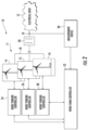
- FIG. 1 illustrates a wind turbine system 110 operable to generate electric power is illustrated.
- the wind turbine system 110 includes a hub 112 having multiple rotor blades 114 mounted thereto.
- the rotor blades 114 convert the mechanical energy of the wind into a rotational torque, which is further converted into electrical energy by the wind turbine system 110.
- the wind turbine system 110 further includes a turbine portion 116 that is operable to convert the mechanical energy of the wind into a rotational torque and a power conversion system 118 that is operable to convert the rotational torque produced by the turbine portion 116 into electrical power.
- a drive train 120 is provided to couple the turbine portion 116 to the power conversion system 118.
- the wind turbine power conversion system 118 typically comprises a doubly fed asynchronous generator with a power electronic converter for rotor field control or a synchronous generator for use with a full power electronic converter interface to collector system 134.
- the turbine portion 116 includes a turbine rotor low-speed shaft 122 that is coupled to the hub 112. Rotational torque is transmitted from rotor low-speed shaft 122 to a generator shaft 124 via drive train 120.
- drive train 120 includes a gear box 126 transmitting torque from low-speed shaft 122 to a high speed shaft 130.
- a high speed shaft 130 is coupled to power conversion system shaft 124 with a coupling element 128.
- Power conversion system 118 is coupled to wind turbine controls 144.
- Wind turbine controls 144 receive signals 146 from the power conversion system that are representative of the operating parameters of the system. Wind turbine controls 144, in response, may generate control signals, for example a pitch signal 156 to change the pitch of blades 114 or a torque signal for the power conversion system. Wind turbine controls 144 are also coupled to a wind farm controller 132.
- an electrical power generation system 10 for generating electrical power is illustrated.
- the electrical power generation system 10 includes a wind farm 11 electrically coupled to an electrical grid 12.
- the electrical grid 12 is utilized to transfer electrical power from the wind farm 11 to electrical loads.
- the wind farm 11 is provided to generate electrical power utilizing wind energy.
- the wind farm 11 includes wind turbines 14, 15, 16 (more generally referenced as “energy sources”), a collector system 18, a transformer 20, wind turbine controllers 24, 26, 28, a measurement device 30, and a wind farm controller 32. It should be noted that a number of wind turbines utilized in the wind farm 11 can vary. For example, the number of wind turbines in the wind farm 11 can be greater than three wind turbines or less than or equal to three wind turbines.
- the wind turbines 14, 15, 16 are provided to generate voltages and currents utilizing wind energy.
- the wind turbines 14, 15, 16 are operably controlled utilizing the wind turbine controllers 24, 26, 28, respectively, which communicate with the wind turbines 14, 15, 16, respectively.
- the wind turbine controllers 24, 26, 28 are configured to generate command signals which control operation of the wind turbines 14, 15, 16, respectively. Further, the wind turbine controllers 24, 26, 28 are provided to measure operational parameters associated with the wind turbines 14, 15, 16 respectively. The wind turbine controllers 24, 26, 28 operably communicate with the wind farm controller 32.
- the collector system 18 is electrically coupled to the wind turbines 14, 15, 16 and routes voltages and currents from each of the turbines to the power transformer 20.
- the power transformer 20 receives the voltages and currents from the wind turbines 14, 15, 16 and outputs a voltage and a current having desired characteristics onto the electrical grid 12. For example, the power transformer 20 can output a voltage having a desired amplitude and a current having a desired amplitude onto the electrical grid 12.
- the measurement device 30 is electrically coupled to a point of interconnection 19 between the transformer 20 and the electrical grid 12.
- the measurement device 30 is configured to measure electrical parameters associated with the electrical grid.
- the measurement device 30 is configured to measure a voltage level (V POI ) at the point of interconnection 19, a real power level (P n ) at the point of interconnection 19, and a frequency level (F n ) at the point of interconnection 19.
- V POI voltage level
- P n real power level
- F n frequency level
- the wind farm controller 32 is provided to control operation of the wind turbines 14, 15, 16 based on measured or estimated parameter values at the point of interconnection 19 associated with either the wind farm 11 or the electrical grid 12.
- the wind farm controller 32 is configured to generate command messages that are received by the wind turbine controllers 24, 26, 28 for controlling operation of the wind turbines 14, 15, 16, respectively.
- the wind turbines 14, 15, 16 can be operated based on various operational modes of operation.
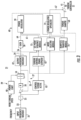
- the control system includes a stabilization system 21 for a power generation system 10 (such as one of the wind turbines 14, 15, 16) connected to a power grid 12.
- the stabilization system 21 includes an input frequency washout 35 configured for tracking slow variations in grid frequency and used for calculating frequency deviations around a center point.
- the stabilization system 21 includes a deadband limiter 25 configured for detecting when a signal 23 from the input frequency washout 35 is outside of a signal range.
- the signal 23 may include any appropriate signal.
- the signal 23 corresponds to system frequency.
- the signal may be obtained either by direct measurement of the respective signal or by measurement of another signal and computations to obtain the respective signal.
- the stabilization system 21 in response to detecting a frequency event, such as a frequency drop or decrease that is outside of the signal range, is configured to activate a control scheme in order to meet one or more grid requirements of the power grid 12 for as long as the signal 23 is outside of the signal range.
- the deadband limiter 25 is configured to limit the frequency deviation signal between frequency threshold values determined by the application.
- Utility grid frequency typically has a nominal value equal to either 50 Hertz (Hz) or 60 Hz. However, the frequency may drift somewhat such that the center point is at a different value such as 59.9 Hz rather than 60 Hz, for example.
- the input frequency washout 35 is used to find the actual frequency rather than the nominal value. Typically, the frequency is measured at a substation of the wind farm 11, but measurement at that location is not required.
- the frequency deadband limiter 25 is used to limit the response of the stabilization system 21 to sufficiently large events.
- the frequency will always vary somewhat due to dithering that occurs when loads come on and off the system.
- load variation typically affects frequency by about 0.05 Hz, depending on the system.
- the stabilization system 21 is useful for more significant events that occur when a sudden difference is present between load and generation. Such significant events may include a utility system losing a large generator or a transmission line tripping.
- the deadband is set to a predetermined value, such as plus or minus 0.12 Hz off the center point frequency. The selection of this limit is typically based on factors such as the location and nature of the power generation system and the variability of frequency center points.
- the stabilization system 21 may have a variable limit that is set by the end user after taking into account such factors.
- the stabilization system 21 may also include a power shaper 33 configured for generating a supplementary power correction factor 56 as a function of the frequency in response to the signal 23 being outside of the signal range.
- the power correction factor 56 may include any linear or non-linear term.
- the power correction factor 56 may be calculated in real-time or may be predetermined static factor pre-programed in the turbine controller 31.
- the stabilization system 21 includes a limit controller 29 configured to prevent the adjustment signal from causing the energy source of the power generation system to operate outside of at least one operating constraint.
- the stabilization system 21 includes a turbine controller 31 for controlling the power generation system 10 based on an adjustment signal 41 for as long as the signal 23 is outside of the respective signal range.
- the power shaper 33 provides a signal for the turbine controller 31 to transiently boost power while staying within energy source operating constraints and limiting coupling between grid oscillatory modes and energy source mechanical modes.
- power could alternatively be used for the same effect, and power as used herein is meant to encompass torque.
- the system may be set up to be based on power throughout, torque throughout, or a combination of power and torque.
- the control scheme is completed for a power response, but implementation is such that the wind turbine obtains a torque command that corresponds to the desired power control.
- the power shaper 33 is configured to shape a pulse in response to the frequency event and decrease the frequency disturbance magnitude in the power generation system.
- the power shaper 33 may be made to address either positive or negative frequency events, the shaper 33 will be particularly useful in embodiments addressing negative frequency events because less alternatives (other than curtailed power operation) exist to momentarily increase power above nominal.
- the limit controller 29 is used to prevent turbine over and under speed operation. Most 60 Hz wind turbines have a predetermined speed range, such as for example from about 800 rotations per minute (rpm) to about 1700 rpm. The goal when the operating constraint is generator rotor speed is to ensure that no request is processed for additional power when the generator is close to the wind turbine cut-in speed limit and that no control signal for reducing power is processed when the generator is close to the wind turbine cut-out speed limit.
- the limit controller 29 includes a power limiter 40 configured to change the bounds of integrator 54 in response to the wind turbine speed (i.e. the generator speed or the rotor speed).
- the generator speed is just one example of an operating constraint and other constraints may be used in addition or alternatively, as discussed below.
- the adjustment signal 41 may include any combination of a power command, a torque command, and/or a speed command.
- the adjustment signal 41 is typically further constrained so as to limit oscillatory coupling. If the grid frequency is oscillatory but at a level smaller than the deadband, no adjustment signal is generated. If the grid is oscillatory and larger than the deadband, then the shaping characteristic prevents the compounding of the oscillation.
- the shape of the power adjustment signal can be controlled by gain and ramp values that will typically vary with application, due to differing utility requirements and responses.
- the illustrated stabilization system 21 further includes an output frequency washout 42 configured to drive an adjustment signal ⁇ P to zero.
- the output frequency washout 42 is shown in the illustrated position for purposes of example only and may be present in any appropriate control block.
- the washout function may be included within control loop 27.
- the stabilization system 21 may include a limiter 34 configured to modify an output of the output frequency washout 42.
- the output of the limiter 34 may be referred to herein as the supplementary power correction factor 56.
- the power shaper 33 includes a gain block 50 and a control loop 27 used to provide a shaping response which is faster upon initiation and slower upon recovery (in other words "fast up, slow down”).
- the gain of block 60 may vary and will typically be set according to location and system requirements.
- the gain block 50 is used to control the rate of signal adjustment for the integrator 54.
- the gain of block 50 is typically a fixed value designed to control the response of the control loop 27.
- the frequency is quickly compensated for upon an event, but the power adjustment after the event recovers slowly.
- the gain block 50 defines the pulse shape and may be varied based on system needs or conditions.
- at least one of the parameter settings for the gain block 50 is configured for having a variable value in response to at least one of a utility condition, a utility command, generator speed, and air density.
- the stabilization system 21 further includes a torque shaper 60 configured to modify the supplementary power correction factor 56 before being used as an input for the turbine controller 31. More specifically, as shown, the torque shaper 60 receives the supplementary power correction factor 56 and applies a tunable gain to the signal via gain block 58 to obtain an adjusted power set point 64.
- the gain may be a function of one or more electrical and/or mechanical system capabilities as well as limits requested from the utility/grid operator.
- the adjusted power set point 64 can then be further modified via one or more modules 70, 72, 74, 76 within the torque shaper 60, which are discussed in more detail below.
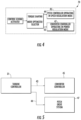
- FIGS. 4-11 illustrates various schematic block diagrams of the various modules 70, 72, 74, 76 of the torque shaper 60 illustrated in FIG. 3 .
- one of the modules of the torque shaper 60 may include an operational mode selector module 70.
- the operational mode selector module 70 allows the turbine controller 31 to assign appropriate regulation functions for the wind turbine 10. More specifically, as shown in FIG. 4 , the mode selector module 70 allows the turbine controller 31 to assign appropriate regulation functions (e.g. torque set point 43 and angle set point 44) for the pitch drive system 47 and the converter controller 45 when the control scheme is activated (as shown at block 82 of FIG. 3 ).
- appropriate regulation functions e.g. torque set point 43 and angle set point 44
- the pitch controller 45 is operating in a speed regulation mode and the converter controller 47 is operating in power regulation mode.
- the control scheme when activated, is configured to optimize operation of the turbine controller 31 such that the power converter operates to regulate power while the pitch system will regulate the speed during the frequency event.
- the power regulator 39 of the turbine controller 31 may generate the torque set point 43 using a proportional integral controller 53.
- the proportional integral controller 53 receives a difference between the power set point of the power generation system 10 and the power feedback from the grid 12. The output of the proportional integral controller 53 may then be fed into a ramp rate limiter 55 that generates the torque set point 43 for the converter controller 45 ( FIG. 5 ).
- the torque set point 43 from the power regulator 39 may be used as an input to the power regulator optimizer module 74, which is further discussed below.
- one of the modules of the torque shaper 60 may include a power set point sequence module 72.
- the power set point sequence module 72 assists to initialize the power set point regulator so as to minimize the error with respect to power feedback, thereby creating a bumpless transfer of the power set point. More specifically, as shown, when the control scheme is activated (as indicated by line 63 changing from zero to one in FIG. 8 ), the power set point sequencing block 57 receives the power feedback 59 from the grid 12 and sets the power command 61 to a pre-event measured grid power (i.e. a measured power of the electrical grid 12 before the frequency event occurs). As such, the torque shaper 60 is configured to adjust the power set point as a function of the supplementary power correction factor 56 so as to temporarily boost the supplied power to the power grid 12 in response to the signal being outside of the respective signal range.
- a temporary power boost may be obtained by temporarily absorbing energy from the energy source.
- the additional energy is available from the turbine inertia and from excess wind.
- other forms of energy storage besides inertia (such as battery storage) can also be used.
- the power may be increased by five to ten percent for up to ten seconds.
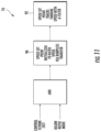
- another one of the modules of the torque shaper 60 may include a power regulator optimization module 74. More specifically, as shown in FIG. 9 , the power regulator optimization module 74 is configured to calculate a torque correction factor 65 as a function of the adjusted power correction factor 64 and a speed 78 of the power generation system 10. In such embodiments, the torque correction factor 65 can be added to the torque set point 43 as a feedforward term to obtain an adjusted torque set point 67. In other words, as shown, the adjusted power correction factor 64 is fed to the power regulator optimization module 74 of the turbine controller 31 in two places: to the power regulator closed loop to ensure that the power regulator is optimized and as a feedforward term for quick response.
- the turbine controller 31 is configured to switch the mode to the above rated mode of operation in response to the signal 23 being outside of the respective signal range. In further embodiments, the turbine controller 31 may also switch the mode back to the below rated mode of operation in response to the signal returning within the respective signal range.
- still another one of the modules of the torque shaper 60 may include a bumpless transfer module 76.
- the module 76 when the control scheme is active 82, the module 76 is configured to optimize operation of the system 10, however, oftentimes, there are multiple control loops active during operation thereof that can reduce the power output of the system 10.
- one of the control loops may include the drivetrain damper of the power generation system 10, which may reduce the power output of the system 10.
- the bumpless transfer module 76 is configured to disable the drivetrain damper of the wind turbine 10 in response to the signal 23 being outside of the respective signal range to prevent a power reduction.
- the bumpless transfer module 76 is configured to disable the drivetrain damper of the wind turbine 10 in response to the signal 23 being outside of the respective signal range to prevent a power reduction.
- the module 76 is configured to determine when the frequency event is over, and then provide a drivetrain damper bumpless transfer 88.
- the module 76 implements the bumpless transfer 88 via a low-pass filter.
- the output of the bumpless transfer module 76 may be fed through a torque damper 68 before being provided to the turbine controller 31.
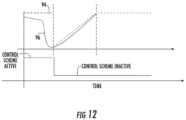
- the speed set point 94 of the system 10 may be initialized or changed to a rated speed via bumpless transfer as shown at block 90. Similar to FIG. 11 , as shown at 92 and FIG. 12 , the speed set point 94 may track the turbine speed 96, e.g. via a low-pass filter. Thus, the module 76 is configured to gradually increase the speed set point 94 based on the tracking until the rated speed is reached so as to smoothly transition out of the control scheme. It should be understood that the speed set point 94 may be ramped back to the rated speed via a fixed or variable rate.
- the bumpless transfer module 76 may transition out of the control scheme when the frequency event is over via a standard or normal operating process.
- the standard operating process may include increasing the adjusted power set point to a predetermined power set point.
- wind turbines are illustrated as the energy sources, the concepts disclosed herein are believed to be applicable to any non-conventional energy sources with several other examples including battery energy storage, microturbines, and/or fuel cells.
- the power obtained from the stabilization system 21 is not supported by the wind, so the turbine will slow down to provide the power from the spinning inertia.
- the energy source includes a generator with a constraint on the rotation speed of the generator.
- operating constraints may include, for example, constraints such as turbine torque (magnitude and time) constraints, ramp rate constraints, and blade pitch operating constraints.
- Torque constraints are typically set based on turbine design (that is, by how much and for how long a turbine can withstand exceeding its rated operating point).
- the output frequency washout 42 can be used to build in protections for such operating constraints.
- the deadband limiter 25, the power shaper 33, the limit controller 29, and/or the torque shaper 60 are embodied in a power generation system controller 32 ( FIG. 2 ).
- the deadband limiter 25, the power shaper 33, the limit controller 29, and/or the torque shaper 60 are embodied in a controller 24 of an energy source 14 ( FIG. 2 ).
- a separate controller (not shown) may be coupled to either the system controller 32 or the source controller 24, or the various control sub-units/functions may be spread among several controllers.
- frequency estimation may be centralized or distributed.
- a frequency signal may be obtained by any desired means with several examples including: measurements at the energy source, measurements at a substation point 19 ( FIG. 2 ), measurements at the utility connection, or information from the utility.
- measurements are obtained at a substation because power fluctuations will tend to modulate apparent frequency (defined as the rate of change of voltage angle) differently at each turbine.
Landscapes
- Engineering & Computer Science (AREA)
- Life Sciences & Earth Sciences (AREA)
- Sustainable Development (AREA)
- Sustainable Energy (AREA)
- Chemical & Material Sciences (AREA)
- Combustion & Propulsion (AREA)
- Mechanical Engineering (AREA)
- General Engineering & Computer Science (AREA)
- Artificial Intelligence (AREA)
- Health & Medical Sciences (AREA)
- Power Engineering (AREA)
- Computer Vision & Pattern Recognition (AREA)
- Evolutionary Computation (AREA)
- Medical Informatics (AREA)
- Software Systems (AREA)
- Physics & Mathematics (AREA)
- General Physics & Mathematics (AREA)
- Automation & Control Theory (AREA)
- Control Of Eletrric Generators (AREA)
- Wind Motors (AREA)
Claims (12)
- Verfahren zum Steuern einer Windturbine (14, 15, 16) eines Windparks (11), die an einem Verbindungspunkt (19) mit einem Stromnetz (12) verbunden ist, wobei das Stromnetz (12) verwendet wird, um elektrische Energie von dem Windpark (11) zu elektrischen Lasten zu übertragen, wobei das Verfahren umfasst:Überwachen einer Frequenz des Stromnetzes (12);
Messen einer Wirkleistung an dem Verbindungspunkt (19), der den Windpark (11) mit dem Stromnetz (12) verbindet, als eine vor dem Ereignis gemessene Netzleistung;als Reaktion auf das Erfassen eines im Stromnetz (12) auftauchenden Frequenzereignisses, Aktivieren eines Steuerungsplans um eine oder mehrere Netzanforderungen des Stromnetzes (12) zu erfüllen, wobei der Steuerungsplan umfasst:Erhöhung der Ausgangsleistung der Windturbine (14, 15, 16) auf mindestens die vor dem Ereignis gemessene Netzleistung am Verbindungspunkt (19);Berechnen eines Leistungskorrekturfaktors für einen Leistungssollwert der Windturbine (14, 15, 16) als eine Funktion von mindestens dem Frequenzereignis;Anpassen des Leistungssollwerts über den Leistungskorrekturfaktor, so dass die Leistungsabgabe einer vorgegebenen Trajektorie folgt;Steuern der Windturbine (14, 15, 16) über eine Turbinensteuerung (24, 26, 28) auf der Grundlage des angepassten Leistungssollwerts, solange der Steuerungsplan aktiviert ist;Anwenden einer Zunahme auf den Leistungskorrekturfaktor, um einen angepassten Leistungskorrekturfaktor zu erhalten, wobei die Zunahme als Funktion einer oder mehrerer elektrischer oder mechanischer Grenzen der Windturbine (14, 15, 16) bestimmt wird; undBerechnen eines Drehmomentkorrekturfaktors (65) als eine Funktion des angepassten Leistungskorrekturfaktors und einer Drehzahl der Windturbine (14, 15, 16);Hinzufügen des Drehmomentkorrekturfaktors zu einem Drehmomentsollwert als ein Vorsteuerungs-Term; undHinzufügen des angepassten Leistungskorrekturfaktors zu dem Leistungssollwert in dem geschlossenen Regelkreis des Leistungsreglers (39). - Verfahren nach Anspruch 1, das ferner das Auferlegen eines Modus oberhalb der Nennleistung umfasst, wenn der Steuerungsplan aktiviert ist, so dass ein Drehzahlregler einen Anstellwinkel steuert und ein Leistungsregler den Drehmomentsollwert steuert.
- Verfahren nach einem der vorhergehenden Ansprüche, das ferner das Umschalten eines Betriebsmodus umfasst, wenn der Steuerungsplan deaktiviert wird, von dem auferlegten Modus oberhalb der Nennleistung zu einem optimalen Betriebszustand oder das Umschalten des Betriebsmodus von dem Betriebsmodus oberhalb der Nennleistung zu einem Betriebsmodus unterhalb der Nennleistung, bei dem der Drehzahlregler den Drehmomentsollwert steuert.
- Verfahren nach einem der vorhergehenden Ansprüche, wobei, wenn die Windturbine (14, 15, 16) im Betriebsmodus unterhalb der Nennleistung arbeitet, wenn das Frequenzereignis erfasst wird, das Verfahren ferner das Umschalten des Modus in den Betriebsmodus oberhalb der Nennleistung umfasst, wenn der Steuerungsplan aktiviert wird.
- Verfahren nach einem der vorhergehenden Ansprüche, ferner umfassend das Umschalten des Modus zurück in den Betriebsmodus unterhalb der Nennleistung, wenn das Frequenzereignis vorüber ist.
- Verfahren nach einem der vorhergehenden Ansprüche, wobei der Steuerungsplan ferner das Ändern eines Drehzahlsollwerts der Windturbine (14, 15, 16) auf eine Nenndrehzahl der Windturbine (14, 15, 16) über einen stoßfreien Übergang umfasst.
- Verfahren nach einem der vorhergehenden Ansprüche, wobei, während des Umschaltens des Modus zurück auf den Betriebsmodus unterhalb der Nennleistung der Schritt des Änderns des Drehzahlsollwerts der Windturbine (14, 15, 16) auf die Nenndrehzahl der Windturbine (14, 15, 16) über den stoßfreien Übergang ferner umfasst:Verfolgen einer aktuellen Drehzahl der Windturbine (14, 15, 16) über mindestens einen Filter; undschrittweises Erhöhen des Drehzahlsollwerts auf der Grundlage des Verfolgens, bis die Nenndrehzahl erreicht ist, um einen sanften Übergang aus dem Steuerungsplan zu erreichen.
- Verfahren nach einem der vorhergehenden Ansprüche, wobei, wenn die Windturbine (14, 15, 16) in dem Betriebsmodus oberhalb der Nennleistung arbeitet, das Verfahren ferner umfasst:
Verlassen des Steuerungsplans, wenn das Frequenzereignis vorbei ist, über einen Standardbetriebsprozess, wobei der Standardbetriebsprozess umfasst:
Erhöhen des eingestellten Leistungssollwerts auf einen vorbestimmten Leistungssollwert. - Verfahren nach einem der vorhergehenden Ansprüche, ferner umfassend das Deaktivieren eines oder mehrerer Regelkreise der Turbinensteuerung (24, 26, 28) für die Dauer der Aktivierung des Steuerungsplans, wobei das Deaktivieren des einen oder der mehreren Regelkreise einen zusätzlichen Leistungsabfall der Windturbine (14, 15, 16) verhindert.
- Stabilisierungssystem (21) für ein Windenergieerzeugungssystem, das an einem Verbindungspunkt (19) mit einem Stromnetz (12) verbunden ist, wobei das Stromnetz (12) verwendet wird, um elektrische Energie von dem Windenergieerzeugungssystem (11) zu elektrischen Lasten zu übertragen, wobei das Stabilisierungssystem (21) umfasst:eine Messvorrichtung (30), die elektrisch mit dem Verbindungspunkt (19) zwischen dem Windenergieerzeugungssystem und dem Stromnetz (12) gekoppelt ist, wobei die Messvorrichtung so konfiguriert ist, dass sie eine Wirkleistung am Verbindungspunkt (19), der den Windpark (11) mit dem Stromnetz (12) verbindet, als eine vor dem Ereignis gemessene Netzleistung misst;einen Totbandbegrenzer (25) zum Erfassen, wenn ein Signal außerhalb eines jeweiligen Signalbereichs liegt, wobei das Signal eine Frequenz umfasst;einen Leistungsformer (33) zum Bereitstellen eines zusätzlichen Leistungskorrekturfaktors als Funktion der Frequenz;einen Drehmomentformer (60) zum anfänglichen Erhöhen einer Leistungsabgabe der Windturbine (14, 15, 16) auf die vor dem Ereignis gemessene Netzleistung am Verbindungspunkt (19) und zum Anpassen des Leistungssollwerts als eine Funktion des zusätzlichen Leistungskorrekturfaktors, um die an das Stromnetz (12) gelieferte Leistung vorübergehend zu erhöhen, als Reaktion auf das Signal, das außerhalb des jeweiligen Signalbereichs liegt; wobei der Drehmomentformer umfasst:eine Turbinensteuerung (24, 26, 28) zum Steuern der Windturbine (14, 15, 16) auf der Grundlage des angepassten Leistungssollwerts, solange das Signal außerhalb des jeweiligen Signalbereichs liegt;einen Verstärkungsblock (50) zum Anwenden einer Verstärkung auf den Leistungskorrekturfaktor, um einen angepassten Leistungskorrekturfaktor zu erhalten, wobei die Verstärkung als eine Funktion von einem oder mehreren elektrischen oder mechanischen Grenzwerten der Windturbine (14, 15, 16) bestimmt wird; undein Leistungsregler-Optimierungsmodul (74) zum Berechnen eines DrehmomentKorrekturfaktors (65) als eine Funktion des angepassten Leistungskorrekturfaktors (64) und einer Drehzahl (78) der Windturbine (14, 15, 16), zum Addieren des Drehmomentkorrekturfaktors zu einem Drehmomentsollwert als Vorsteuerungs-Term, und zum Addieren des angepassten Leistungskorrekturfaktors zu dem Leistungssollwert in dem geschlossenen Regelkreis des Leistungsreglers (39).
- Stabilisierungssystem (21) nach Anspruch 10, das ferner einen Betriebsmodus-Auswähler zum Bestimmen eines Betriebsmodus der Windturbine (14, 15, 16) umfasst, wobei der Betriebsmodus-Auswähler so konfiguriert ist, dass er einen Modus oberhalb der Nennleistung auferlegt, wenn das Steuerschema aktiviert ist, so dass ein Drehzahlregler einen Anstellwinkel regelt und ein Leistungsregler den Drehmomentsollwert regelt, wobei der Betriebsmodus-Auswähler ferner so konfiguriert ist, dass er einen Betriebsmodus umschaltet, wenn das Steuerschema deaktiviert wird, und zwar von dem auferlegten Modus oberhalb der Nennleistung zu einem optimalen Betriebszustand oder den Betriebsmodus oberhalb der Nennleistung zu einem Betriebsmodus unterhalb der Nennleistung umschaltet, in dem der Drehzahlregler den Drehmomentsollwert steuert.
- Stabilisierungssystem (21) nach einem der Ansprüche 10 oder 11, das ferner ein Modul für den stoßfreien Übergang zum Ändern eines Drehzahlsollwerts der Windturbine (14, 15, 16) auf eine Nenndrehzahl der Windturbine (14, 15, 16) umfasst, während der Betriebsmodus zurück auf den Betriebsmodus unterhalb der Nennleistung umgeschaltet wird, das stoßfreie Übergangsmodul, das einen Tiefpassfilter zum Verfolgen einer aktuellen Drehzahl der Windturbine (14, 15, 16) und zum allmählichen Erhöhen des Drehzahlsollwerts auf der Grundlage der Verfolgung umfasst, bis die Nenndrehzahl erreicht ist, um einen sanften Übergang aus dem Steuerplan zu ermöglichen.
Applications Claiming Priority (1)
| Application Number | Priority Date | Filing Date | Title |
|---|---|---|---|
| IN201741017643 | 2017-05-19 |
Publications (2)
| Publication Number | Publication Date |
|---|---|
| EP3404258A1 EP3404258A1 (de) | 2018-11-21 |
| EP3404258B1 true EP3404258B1 (de) | 2025-04-16 |
Family
ID=62167194
Family Applications (1)
| Application Number | Title | Priority Date | Filing Date |
|---|---|---|---|
| EP18172275.2A Active EP3404258B1 (de) | 2017-05-19 | 2018-05-15 | Steuerungssysteme und -verfahren zur stromerzeugung |
Country Status (4)
| Country | Link |
|---|---|
| US (1) | US10731633B2 (de) |
| EP (1) | EP3404258B1 (de) |
| DK (1) | DK3404258T3 (de) |
| ES (1) | ES3035696T3 (de) |
Families Citing this family (9)
| Publication number | Priority date | Publication date | Assignee | Title |
|---|---|---|---|---|
| DE102016125947A1 (de) * | 2016-12-30 | 2018-07-05 | Wobben Properties Gmbh | Verfahren zum Steuern eines elektrischen Verteilnetzes |
| DE102018116446A1 (de) * | 2018-07-06 | 2020-01-09 | Wobben Properties Gmbh | Windenergiesystem und Verfahren zum Erkennen niederfrequenter Schwingungen in einem elektrischen Versorgungsnetz |
| GB201908897D0 (en) * | 2019-06-21 | 2019-08-07 | Univ Birmingham | Fast frequency support from wind turbine systemS |
| US10975847B1 (en) * | 2019-11-08 | 2021-04-13 | General Electric Company | System and method for farm-level control of transient power boost during frequency events |
| US12051907B2 (en) | 2020-02-26 | 2024-07-30 | Vestas Wind Systems A/S | Method for controlling a renewable power plant during voltage events |
| CN115839305B (zh) | 2021-09-22 | 2023-11-28 | 北京金风科创风电设备有限公司 | 风储联合调频方法和风储联合调频装置 |
| CN115940296B (zh) * | 2021-09-22 | 2024-05-17 | 北京金风科创风电设备有限公司 | 风储联合惯量响应方法和惯量响应装置 |
| CN120239783A (zh) * | 2022-11-17 | 2025-07-01 | 通用电气可再生能源西班牙有限公司 | 用于控制风力涡轮的系统和方法 |
| US12492678B1 (en) * | 2024-11-19 | 2025-12-09 | Vestas Wind Systems A/S | Method for controlling a power output of a grid forming wind turbine |
Family Cites Families (13)
| Publication number | Priority date | Publication date | Assignee | Title |
|---|---|---|---|---|
| US7528496B2 (en) | 2003-09-03 | 2009-05-05 | Repower Systems Ag | Method for operating or controlling a wind turbine and method for providing primary control power by means of wind turbines |
| US8237301B2 (en) * | 2008-01-31 | 2012-08-07 | General Electric Company | Power generation stabilization control systems and methods |
| ES2561842T3 (es) | 2009-06-29 | 2016-03-01 | Vestas Wind Systems A/S | Turbina eólica que proporciona soporte a la red de distribución |
| DE102010014165A1 (de) | 2010-04-08 | 2011-10-13 | Repower Systems Ag | Dynamische Trägheitsregelung |
| US9728969B2 (en) * | 2011-05-31 | 2017-08-08 | Vestas Wind Systems A/S | Systems and methods for generating an inertial response to a change in the voltage of an electricial grid |
| EP2679809A1 (de) | 2012-06-28 | 2014-01-01 | Siemens Aktiengesellschaft | Verfahren und Anordnung zur Reaktion auf ein Netz-Ereignis, wie beispielsweise schneller Frequenzausfall, durch Kombinieren von Anfragereaktion, Trägheitsreaktion und Drehungsreserve |
| EP2896101B1 (de) * | 2012-09-14 | 2016-11-09 | Vestas Wind Systems A/S | Kraftwerksteuerung während eines niederspannungs- oder hochspannungsereignisses |
| WO2014090255A1 (en) * | 2012-12-14 | 2014-06-19 | Vestas Wind Systems A/S | Method and arrangement for swift power regulation |
| US9450416B2 (en) * | 2013-07-16 | 2016-09-20 | Siemens Aktiengesellschaft | Wind turbine generator controller responsive to grid frequency change |
| EP3007298A1 (de) | 2014-10-07 | 2016-04-13 | Siemens Aktiengesellschaft | Generische Frequenzantwort für Windkraftsysteme |
| US20160160839A1 (en) | 2014-12-09 | 2016-06-09 | State Grid Corporation Of China | Method for controlling inertia response of variable-speed wind turbine generator |
| EP3096004A1 (de) | 2015-05-18 | 2016-11-23 | ABB Technology AG | Windparkträgheitsreaktion |
| WO2017059862A1 (en) * | 2015-10-09 | 2017-04-13 | Vestas Wind Systems A/S | Power boost of a wind turbine using model predictive control |
-
2018
- 2018-05-11 US US15/977,179 patent/US10731633B2/en active Active
- 2018-05-15 DK DK18172275.2T patent/DK3404258T3/da active
- 2018-05-15 ES ES18172275T patent/ES3035696T3/es active Active
- 2018-05-15 EP EP18172275.2A patent/EP3404258B1/de active Active
Also Published As
| Publication number | Publication date |
|---|---|
| US10731633B2 (en) | 2020-08-04 |
| US20180335020A1 (en) | 2018-11-22 |
| EP3404258A1 (de) | 2018-11-21 |
| ES3035696T3 (en) | 2025-09-08 |
| DK3404258T3 (da) | 2025-06-30 |
Similar Documents
| Publication | Publication Date | Title |
|---|---|---|
| EP3404258B1 (de) | Steuerungssysteme und -verfahren zur stromerzeugung | |
| US8237301B2 (en) | Power generation stabilization control systems and methods | |
| US8994200B2 (en) | Power system frequency inertia for power generation system | |
| JP5339451B2 (ja) | 励磁機及び系統に接続されていない電力変換器を有する可変速風力タービンの発電ブレーキ(dynamicelectricbrake) | |
| CN102301584B (zh) | 风力涡轮系统和稳定公用系统的频率和功率摆动的方法 | |
| EP2847457B1 (de) | Stromsystem und verfahren zum betreiben einer windenergieanlage mit einem verteilungsalgorithmus | |
| EP2688172B1 (de) | Verfahren und Vorrichtung zur adaptiven Steuerung von Windparkturbinen | |
| US12173692B2 (en) | Method of operating a wind turbine and control system | |
| KR20180105692A (ko) | 전기 공급 네트워크에 전력을 공급하기 위한 방법 | |
| KR20200017472A (ko) | 컨버터 제어형 발전 유닛, 특히 풍력 발전 설비에 의해 전력을 공급하기 위한 방법 | |
| WO2024167493A1 (en) | Grid-forming island detection and continuous operation of an inverter-based resource | |
| Guo et al. | Nonlinear control of wind power generation systems | |
| Rosyadi et al. | Damping load frequency in multi-area power system using wind farm cooperated Primary Load Frequency Control | |
| ADILOV et al. | CONTROLLING THE FREQUENCY OF ELECTRICITY PRODUCED BY A LARGE WIND FARM | |
| WO2024136833A1 (en) | System and method for coordinated frequency response of an inverter-based resource to grid frequency changes | |
| WO2026084712A1 (en) | System and method for coordinated frequency response of an inverter-based resource to grid frequency changes | |
| WO2025140765A1 (en) | A method to limit current for grid forming wind turbine | |
| AU2011203021A1 (en) | Dynamic Electric Brake For A Variable Speed Wind Turbine Having An Exciter Machine and a Power Converter Not Connected To The Grid |
Legal Events
| Date | Code | Title | Description |
|---|---|---|---|
| PUAI | Public reference made under article 153(3) epc to a published international application that has entered the european phase |
Free format text: ORIGINAL CODE: 0009012 |
|
| STAA | Information on the status of an ep patent application or granted ep patent |
Free format text: STATUS: THE APPLICATION HAS BEEN PUBLISHED |
|
| AK | Designated contracting states |
Kind code of ref document: A1 Designated state(s): AL AT BE BG CH CY CZ DE DK EE ES FI FR GB GR HR HU IE IS IT LI LT LU LV MC MK MT NL NO PL PT RO RS SE SI SK SM TR |
|
| AX | Request for extension of the european patent |
Extension state: BA ME |
|
| STAA | Information on the status of an ep patent application or granted ep patent |
Free format text: STATUS: REQUEST FOR EXAMINATION WAS MADE |
|
| 17P | Request for examination filed |
Effective date: 20190521 |
|
| RBV | Designated contracting states (corrected) |
Designated state(s): AL AT BE BG CH CY CZ DE DK EE ES FI FR GB GR HR HU IE IS IT LI LT LU LV MC MK MT NL NO PL PT RO RS SE SI SK SM TR |
|
| STAA | Information on the status of an ep patent application or granted ep patent |
Free format text: STATUS: EXAMINATION IS IN PROGRESS |
|
| 17Q | First examination report despatched |
Effective date: 20220201 |
|
| P01 | Opt-out of the competence of the unified patent court (upc) registered |
Effective date: 20230530 |
|
| RAP1 | Party data changed (applicant data changed or rights of an application transferred) |
Owner name: GENERAL ELECTRIC RENOVABLES ESPANA, S.L. |
|
| GRAP | Despatch of communication of intention to grant a patent |
Free format text: ORIGINAL CODE: EPIDOSNIGR1 |
|
| STAA | Information on the status of an ep patent application or granted ep patent |
Free format text: STATUS: GRANT OF PATENT IS INTENDED |
|
| INTG | Intention to grant announced |
Effective date: 20241202 |
|
| GRAS | Grant fee paid |
Free format text: ORIGINAL CODE: EPIDOSNIGR3 |
|
| GRAA | (expected) grant |
Free format text: ORIGINAL CODE: 0009210 |
|
| STAA | Information on the status of an ep patent application or granted ep patent |
Free format text: STATUS: THE PATENT HAS BEEN GRANTED |
|
| AK | Designated contracting states |
Kind code of ref document: B1 Designated state(s): AL AT BE BG CH CY CZ DE DK EE ES FI FR GB GR HR HU IE IS IT LI LT LU LV MC MK MT NL NO PL PT RO RS SE SI SK SM TR |
|
| REG | Reference to a national code |
Ref country code: GB Ref legal event code: FG4D |
|
| REG | Reference to a national code |
Ref country code: CH Ref legal event code: EP Ref country code: DE Ref legal event code: R096 Ref document number: 602018081097 Country of ref document: DE |
|
| REG | Reference to a national code |
Ref country code: IE Ref legal event code: FG4D |
|
| REG | Reference to a national code |
Ref country code: DK Ref legal event code: T3 Effective date: 20250627 |
|
| PGFP | Annual fee paid to national office [announced via postgrant information from national office to epo] |
Ref country code: DE Payment date: 20250423 Year of fee payment: 8 |
|
| PGFP | Annual fee paid to national office [announced via postgrant information from national office to epo] |
Ref country code: ES Payment date: 20250604 Year of fee payment: 8 Ref country code: DK Payment date: 20250625 Year of fee payment: 8 |
|
| REG | Reference to a national code |
Ref country code: NL Ref legal event code: MP Effective date: 20250416 |
|
| REG | Reference to a national code |
Ref country code: ES Ref legal event code: FG2A Ref document number: 3035696 Country of ref document: ES Kind code of ref document: T3 Effective date: 20250908 |
|
| PG25 | Lapsed in a contracting state [announced via postgrant information from national office to epo] |
Ref country code: NL Free format text: LAPSE BECAUSE OF FAILURE TO SUBMIT A TRANSLATION OF THE DESCRIPTION OR TO PAY THE FEE WITHIN THE PRESCRIBED TIME-LIMIT Effective date: 20250416 |
|
| REG | Reference to a national code |
Ref country code: AT Ref legal event code: MK05 Ref document number: 1785850 Country of ref document: AT Kind code of ref document: T Effective date: 20250416 |
|
| PG25 | Lapsed in a contracting state [announced via postgrant information from national office to epo] |
Ref country code: PT Free format text: LAPSE BECAUSE OF FAILURE TO SUBMIT A TRANSLATION OF THE DESCRIPTION OR TO PAY THE FEE WITHIN THE PRESCRIBED TIME-LIMIT Effective date: 20250818 Ref country code: FI Free format text: LAPSE BECAUSE OF FAILURE TO SUBMIT A TRANSLATION OF THE DESCRIPTION OR TO PAY THE FEE WITHIN THE PRESCRIBED TIME-LIMIT Effective date: 20250416 |
|
| REG | Reference to a national code |
Ref country code: LT Ref legal event code: MG9D |
|
| PG25 | Lapsed in a contracting state [announced via postgrant information from national office to epo] |
Ref country code: GR Free format text: LAPSE BECAUSE OF FAILURE TO SUBMIT A TRANSLATION OF THE DESCRIPTION OR TO PAY THE FEE WITHIN THE PRESCRIBED TIME-LIMIT Effective date: 20250717 Ref country code: NO Free format text: LAPSE BECAUSE OF FAILURE TO SUBMIT A TRANSLATION OF THE DESCRIPTION OR TO PAY THE FEE WITHIN THE PRESCRIBED TIME-LIMIT Effective date: 20250716 |
|
| PG25 | Lapsed in a contracting state [announced via postgrant information from national office to epo] |
Ref country code: PL Free format text: LAPSE BECAUSE OF FAILURE TO SUBMIT A TRANSLATION OF THE DESCRIPTION OR TO PAY THE FEE WITHIN THE PRESCRIBED TIME-LIMIT Effective date: 20250416 |
|
| PG25 | Lapsed in a contracting state [announced via postgrant information from national office to epo] |
Ref country code: BG Free format text: LAPSE BECAUSE OF FAILURE TO SUBMIT A TRANSLATION OF THE DESCRIPTION OR TO PAY THE FEE WITHIN THE PRESCRIBED TIME-LIMIT Effective date: 20250416 |
|
| PG25 | Lapsed in a contracting state [announced via postgrant information from national office to epo] |
Ref country code: HR Free format text: LAPSE BECAUSE OF FAILURE TO SUBMIT A TRANSLATION OF THE DESCRIPTION OR TO PAY THE FEE WITHIN THE PRESCRIBED TIME-LIMIT Effective date: 20250416 |
|
| PG25 | Lapsed in a contracting state [announced via postgrant information from national office to epo] |
Ref country code: AT Free format text: LAPSE BECAUSE OF FAILURE TO SUBMIT A TRANSLATION OF THE DESCRIPTION OR TO PAY THE FEE WITHIN THE PRESCRIBED TIME-LIMIT Effective date: 20250416 |
|
| PG25 | Lapsed in a contracting state [announced via postgrant information from national office to epo] |
Ref country code: RS Free format text: LAPSE BECAUSE OF FAILURE TO SUBMIT A TRANSLATION OF THE DESCRIPTION OR TO PAY THE FEE WITHIN THE PRESCRIBED TIME-LIMIT Effective date: 20250716 |
|
| PG25 | Lapsed in a contracting state [announced via postgrant information from national office to epo] |
Ref country code: IS Free format text: LAPSE BECAUSE OF FAILURE TO SUBMIT A TRANSLATION OF THE DESCRIPTION OR TO PAY THE FEE WITHIN THE PRESCRIBED TIME-LIMIT Effective date: 20250816 |
|
| PG25 | Lapsed in a contracting state [announced via postgrant information from national office to epo] |
Ref country code: LV Free format text: LAPSE BECAUSE OF FAILURE TO SUBMIT A TRANSLATION OF THE DESCRIPTION OR TO PAY THE FEE WITHIN THE PRESCRIBED TIME-LIMIT Effective date: 20250416 |
|
| REG | Reference to a national code |
Ref country code: CH Ref legal event code: H13 Free format text: ST27 STATUS EVENT CODE: U-0-0-H10-H13 (AS PROVIDED BY THE NATIONAL OFFICE) Effective date: 20251223 |
|
| PG25 | Lapsed in a contracting state [announced via postgrant information from national office to epo] |
Ref country code: SM Free format text: LAPSE BECAUSE OF FAILURE TO SUBMIT A TRANSLATION OF THE DESCRIPTION OR TO PAY THE FEE WITHIN THE PRESCRIBED TIME-LIMIT Effective date: 20250416 |
|
| PG25 | Lapsed in a contracting state [announced via postgrant information from national office to epo] |
Ref country code: LU Free format text: LAPSE BECAUSE OF NON-PAYMENT OF DUE FEES Effective date: 20250515 |
|
| PG25 | Lapsed in a contracting state [announced via postgrant information from national office to epo] |
Ref country code: CH Free format text: LAPSE BECAUSE OF NON-PAYMENT OF DUE FEES Effective date: 20250531 |
|
| REG | Reference to a national code |
Ref country code: DE Ref legal event code: R097 Ref document number: 602018081097 Country of ref document: DE |
|
| PG25 | Lapsed in a contracting state [announced via postgrant information from national office to epo] |
Ref country code: CZ Free format text: LAPSE BECAUSE OF FAILURE TO SUBMIT A TRANSLATION OF THE DESCRIPTION OR TO PAY THE FEE WITHIN THE PRESCRIBED TIME-LIMIT Effective date: 20250416 |
|
| PG25 | Lapsed in a contracting state [announced via postgrant information from national office to epo] |
Ref country code: EE Free format text: LAPSE BECAUSE OF FAILURE TO SUBMIT A TRANSLATION OF THE DESCRIPTION OR TO PAY THE FEE WITHIN THE PRESCRIBED TIME-LIMIT Effective date: 20250416 |
|
| PG25 | Lapsed in a contracting state [announced via postgrant information from national office to epo] |
Ref country code: RO Free format text: LAPSE BECAUSE OF FAILURE TO SUBMIT A TRANSLATION OF THE DESCRIPTION OR TO PAY THE FEE WITHIN THE PRESCRIBED TIME-LIMIT Effective date: 20250416 Ref country code: SK Free format text: LAPSE BECAUSE OF FAILURE TO SUBMIT A TRANSLATION OF THE DESCRIPTION OR TO PAY THE FEE WITHIN THE PRESCRIBED TIME-LIMIT Effective date: 20250416 |
|
| PG25 | Lapsed in a contracting state [announced via postgrant information from national office to epo] |
Ref country code: IT Free format text: LAPSE BECAUSE OF FAILURE TO SUBMIT A TRANSLATION OF THE DESCRIPTION OR TO PAY THE FEE WITHIN THE PRESCRIBED TIME-LIMIT Effective date: 20250416 |
|
| REG | Reference to a national code |
Ref country code: BE Ref legal event code: MM Effective date: 20250531 |
|
| PG25 | Lapsed in a contracting state [announced via postgrant information from national office to epo] |
Ref country code: MC Free format text: LAPSE BECAUSE OF FAILURE TO SUBMIT A TRANSLATION OF THE DESCRIPTION OR TO PAY THE FEE WITHIN THE PRESCRIBED TIME-LIMIT Effective date: 20250416 |
|
| PLBE | No opposition filed within time limit |
Free format text: ORIGINAL CODE: 0009261 |
|
| STAA | Information on the status of an ep patent application or granted ep patent |
Free format text: STATUS: NO OPPOSITION FILED WITHIN TIME LIMIT |
|
| REG | Reference to a national code |
Ref country code: CH Ref legal event code: L10 Free format text: ST27 STATUS EVENT CODE: U-0-0-L10-L00 (AS PROVIDED BY THE NATIONAL OFFICE) Effective date: 20260225 |
|
| 26N | No opposition filed |
Effective date: 20260119 |
|
| GBPC | Gb: european patent ceased through non-payment of renewal fee |
Effective date: 20250716 |
|
| PG25 | Lapsed in a contracting state [announced via postgrant information from national office to epo] |
Ref country code: GB Free format text: LAPSE BECAUSE OF NON-PAYMENT OF DUE FEES Effective date: 20250716 |
|
| PG25 | Lapsed in a contracting state [announced via postgrant information from national office to epo] |
Ref country code: IE Free format text: LAPSE BECAUSE OF NON-PAYMENT OF DUE FEES Effective date: 20250515 |
|
| PG25 | Lapsed in a contracting state [announced via postgrant information from national office to epo] |
Ref country code: BE Free format text: LAPSE BECAUSE OF NON-PAYMENT OF DUE FEES Effective date: 20250531 |
|
| PG25 | Lapsed in a contracting state [announced via postgrant information from national office to epo] |
Ref country code: FR Free format text: LAPSE BECAUSE OF NON-PAYMENT OF DUE FEES Effective date: 20250616 |