EP3404251A1 - Portable gasoline tool and electronic ignition system thereof - Google Patents
Portable gasoline tool and electronic ignition system thereof Download PDFInfo
- Publication number
- EP3404251A1 EP3404251A1 EP17738211.6A EP17738211A EP3404251A1 EP 3404251 A1 EP3404251 A1 EP 3404251A1 EP 17738211 A EP17738211 A EP 17738211A EP 3404251 A1 EP3404251 A1 EP 3404251A1
- Authority
- EP
- European Patent Office
- Prior art keywords
- voltage
- ignition
- voltage boosting
- flywheel
- controller
- Prior art date
- Legal status (The legal status is an assumption and is not a legal conclusion. Google has not performed a legal analysis and makes no representation as to the accuracy of the status listed.)
- Pending
Links
Images


Classifications
-
- F—MECHANICAL ENGINEERING; LIGHTING; HEATING; WEAPONS; BLASTING
- F02—COMBUSTION ENGINES; HOT-GAS OR COMBUSTION-PRODUCT ENGINE PLANTS
- F02N—STARTING OF COMBUSTION ENGINES; STARTING AIDS FOR SUCH ENGINES, NOT OTHERWISE PROVIDED FOR
- F02N11/00—Starting of engines by means of electric motors
- F02N11/08—Circuits or control means specially adapted for starting of engines
- F02N11/0862—Circuits or control means specially adapted for starting of engines characterised by the electrical power supply means, e.g. battery
-
- F—MECHANICAL ENGINEERING; LIGHTING; HEATING; WEAPONS; BLASTING
- F02—COMBUSTION ENGINES; HOT-GAS OR COMBUSTION-PRODUCT ENGINE PLANTS
- F02P—IGNITION, OTHER THAN COMPRESSION IGNITION, FOR INTERNAL-COMBUSTION ENGINES; TESTING OF IGNITION TIMING IN COMPRESSION-IGNITION ENGINES
- F02P3/00—Other installations
- F02P3/02—Other installations having inductive energy storage, e.g. arrangements of induction coils
- F02P3/04—Layout of circuits
- F02P3/05—Layout of circuits for control of the magnitude of the current in the ignition coil
-
- F—MECHANICAL ENGINEERING; LIGHTING; HEATING; WEAPONS; BLASTING
- F02—COMBUSTION ENGINES; HOT-GAS OR COMBUSTION-PRODUCT ENGINE PLANTS
- F02B—INTERNAL-COMBUSTION PISTON ENGINES; COMBUSTION ENGINES IN GENERAL
- F02B63/00—Adaptations of engines for driving pumps, hand-held tools or electric generators; Portable combinations of engines with engine-driven devices
-
- F—MECHANICAL ENGINEERING; LIGHTING; HEATING; WEAPONS; BLASTING
- F02—COMBUSTION ENGINES; HOT-GAS OR COMBUSTION-PRODUCT ENGINE PLANTS
- F02N—STARTING OF COMBUSTION ENGINES; STARTING AIDS FOR SUCH ENGINES, NOT OTHERWISE PROVIDED FOR
- F02N11/00—Starting of engines by means of electric motors
- F02N11/08—Circuits or control means specially adapted for starting of engines
-
- F—MECHANICAL ENGINEERING; LIGHTING; HEATING; WEAPONS; BLASTING
- F02—COMBUSTION ENGINES; HOT-GAS OR COMBUSTION-PRODUCT ENGINE PLANTS
- F02P—IGNITION, OTHER THAN COMPRESSION IGNITION, FOR INTERNAL-COMBUSTION ENGINES; TESTING OF IGNITION TIMING IN COMPRESSION-IGNITION ENGINES
- F02P5/00—Advancing or retarding ignition; Control therefor
- F02P5/04—Advancing or retarding ignition; Control therefor automatically, as a function of the working conditions of the engine or vehicle or of the atmospheric conditions
- F02P5/145—Advancing or retarding ignition; Control therefor automatically, as a function of the working conditions of the engine or vehicle or of the atmospheric conditions using electrical means
- F02P5/15—Digital data processing
- F02P5/1502—Digital data processing using one central computing unit
-
- F—MECHANICAL ENGINEERING; LIGHTING; HEATING; WEAPONS; BLASTING
- F02—COMBUSTION ENGINES; HOT-GAS OR COMBUSTION-PRODUCT ENGINE PLANTS
- F02P—IGNITION, OTHER THAN COMPRESSION IGNITION, FOR INTERNAL-COMBUSTION ENGINES; TESTING OF IGNITION TIMING IN COMPRESSION-IGNITION ENGINES
- F02P9/00—Electric spark ignition control, not otherwise provided for
-
- F—MECHANICAL ENGINEERING; LIGHTING; HEATING; WEAPONS; BLASTING
- F02—COMBUSTION ENGINES; HOT-GAS OR COMBUSTION-PRODUCT ENGINE PLANTS
- F02N—STARTING OF COMBUSTION ENGINES; STARTING AIDS FOR SUCH ENGINES, NOT OTHERWISE PROVIDED FOR
- F02N11/00—Starting of engines by means of electric motors
- F02N11/08—Circuits or control means specially adapted for starting of engines
- F02N2011/0881—Components of the circuit not provided for by previous groups
-
- F—MECHANICAL ENGINEERING; LIGHTING; HEATING; WEAPONS; BLASTING
- F16—ENGINEERING ELEMENTS AND UNITS; GENERAL MEASURES FOR PRODUCING AND MAINTAINING EFFECTIVE FUNCTIONING OF MACHINES OR INSTALLATIONS; THERMAL INSULATION IN GENERAL
- F16F—SPRINGS; SHOCK-ABSORBERS; MEANS FOR DAMPING VIBRATION
- F16F15/00—Suppression of vibrations in systems; Means or arrangements for avoiding or reducing out-of-balance forces, e.g. due to motion
- F16F15/30—Flywheels
-
- Y—GENERAL TAGGING OF NEW TECHNOLOGICAL DEVELOPMENTS; GENERAL TAGGING OF CROSS-SECTIONAL TECHNOLOGIES SPANNING OVER SEVERAL SECTIONS OF THE IPC; TECHNICAL SUBJECTS COVERED BY FORMER USPC CROSS-REFERENCE ART COLLECTIONS [XRACs] AND DIGESTS
- Y02—TECHNOLOGIES OR APPLICATIONS FOR MITIGATION OR ADAPTATION AGAINST CLIMATE CHANGE
- Y02T—CLIMATE CHANGE MITIGATION TECHNOLOGIES RELATED TO TRANSPORTATION
- Y02T10/00—Road transport of goods or passengers
- Y02T10/10—Internal combustion engine [ICE] based vehicles
- Y02T10/40—Engine management systems
Definitions
- the present invention relates to a portable gasoline tool and an electronic ignition system thereof.
- a portable gasoline tool is often used in the area of garden greening, and its electronic ignition system is a key system therein.
- the electronic ignition system mainly comprises a flywheel, a voltage boosting device, and a spark plug, and mainly functioning to ignite, with a spark produced by the spark plug driven by a high voltage coil, the combustible gas mixture introduced into the combustion chamber, to make it explode to release energy.
- the electronic ignition system operates at a most suitable ignition angle and gives out sufficient ignition voltage such that the gasoline engine of the portable gasoline tool can run smoothly and has an improved efficiency.
- the commonly used electronic ignition system comprises a magnet motor, an igniter, an inductive coil provided on the cylinder, and a permanent magnet mounted on the flywheel.
- the permanent magnet is rotated with the flywheel, and every time it meets the inductive coil fixed on the cylinder around a circle, an inductive current is produced in the inductive coil (as in an electric generator in principle).
- An electric circuit is used to amplify the coil inductive current into a voltage of tens of kV such that the spark plug connected thereto and placed in parallel in the combustion chamber of the gasoline engine, ignites.
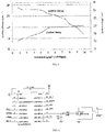
- the electronic ignition system has the following defects: the voltage is proportional to the rotation speed, and when the rotation speed is relatively low, the produced inductive current is small and the ignition voltage is relatively low wherein the relation of the ignition time point, the ignition voltage and the rotation speed is shown in FIG. 1 . Moreover, in the start-up stage, the rotation speed is relatively low, the ignition voltage cannot produce a large spark needed at this time and it is adverse to ignition, resulting in the difficulties to start the gasoline engine for the user to employ.
- the technical problem to be solved by the present invention is to provide a portable gasoline tool and an electronic ignition system thereof wherein the operation is simple and convenient, it can be started even if the rotation speed is relatively low in the start-up stage, enabling an enhanced user experience and facilitating popularization and promotion of the product.
- the first technical solution of the present invention is: an electronic ignition system for a portable gasoline tool, comprising a voltage boosting device and a spark plug connected with an output of the voltage boosting device; the electronic ignition system for the portable gasoline tool further comprises a DC power source and a controller electrically connected with the DC power source and connected with the voltage boosting device, wherein the controller controls ignition voltage and an ignition advance angle.
- the voltage boosting device boosts an output voltage of the DC power source to an ignition voltage; the output voltage of the DC power source is 6 V ⁇ 12 V, and the ignition voltage is 10 kV ⁇ 30 kV.
- the ignition voltage is 15 kV ⁇ 30 kV.
- the voltage boosting device comprises a plurality of stages of voltage boosting units; an output voltage of the lithium battery is boosted, through the plurality of stages of voltage boosting units, to the ignition voltage.
- the voltage boosting device comprises a first-stage voltage boosting unit and a second-stage voltage boosting unit, the first-stage voltage boosting unit boosts the voltage from the output voltage of the lithium battery to 200 V ⁇ 250 V, and the second-stage voltage boosting unit further boosts the voltage from 200 V ⁇ 250 V to the ignition voltage.
- the portable gasoline tool comprises: a body, and a flywheel provided on the body; the electronic ignition system further comprises: a sensing element provided on the flywheel or the body, and a position sensor provided on the body or the flywheel to obtain a rotation speed of the flywheel through the sensing element; the controller controls the ignition voltage and the ignition advance angle according to the rotation speed of the flywheel.
- the sensing element is provided on the flywheel and it is a magnet, with its number being at least one; the position sensor is provided on the body, with its number being one.
- the sensing element is provided on the flywheel and it is Fe, with its number being at least one; the position sensor is provided on the body, with its number being one, wherein the position sensor is an approach switch.
- the DC power source is a Li battery; the controller is an MCU controller.
- the DC power source is removable and rechargeable.
- the electronic ignition system further comprises a temperature sensor connected with the controller, the temperature sensor obtains an ambient temperature; the controller can control the ignition voltage and the ignition advance angle according to the ambient temperature.
- the voltage boosting device comprises an ignition coil.
- the second technical solution of the present invention is: a portable gasoline tool, comprising a body, a cylinder provided in the body, a piston movable to and fro in the cylinder, a crankshaft co-moved with the piston, a flywheel provided on the body and driven by the crankshaft to rotate, and the electronic ignition system described above.
- the controller with an MCU design can precisely control the ignition angle and energy.
- the controller can, with the change in rotation speed as detected by the position sensor, adjust the ignition angle at the appropriate time, thus making the gasoline engine work more stably.
- the operation is simple and convenient, and it can be started even if the rotation speed is relatively low in the start-up stage, thus enabling an enhanced user experience and facilitating popularization and promotion of the product.
- a first embodiment of an electronic ignition system for a portable gasoline tool comprising: a voltage boosting device and a spark plug 40 connected with an output of the voltage boosting device.
- the electronic ignition system for the portable gasoline tool further comprises a Direct Current (DC) power source 70 and a controller electrically connected with the DC power source 70 and connected with the voltage boosting device.
- the DC power source 70 is preferably a Li battery, more preferably a removable rechargeable lithium battery.
- the controller is a Micro Control Unit (MCU) controller, wherein the controller controls ignition voltage and an ignition advance angle.
- MCU Micro Control Unit
- a second embodiment of an electronic ignition system for a portable gasoline tool wherein the portable gasoline tool comprises: a body 10, and a flywheel 30 provided on the body 10 and drawn manually or electrically.
- the electronic ignition system for the portable gasoline tool comprises a voltage boosting device and a spark plug 40 connected with an output of the voltage boosting device.
- the electronic ignition system for the portable gasoline tool further comprises: a sensing element provided on the flywheel 30 or the body 10, and a position sensor 50 provided on the body 10 or the flywheel 30 to obtain a rotation speed of the flywheel 30 through the sensing element, and a controller electrically connected with the position sensor 50 and connected with the voltage boosting device, wherein the controller controls ignition voltage and an ignition advance angle.
- the sensing element is provided on the flywheel 30 and it is a magnet, with its number being at least two; and the position sensor 50 is provided on the body 10, with its number being one.
- the position sensor 50 is preferably a Hall element, or may be a photoelectric element or other elements.
- the sensing element comprises a positioning magnet 32 for initial positioning, and a measuring magnet 34 for rotation speed measurement, wherein the positioning magnet 32 is also referred as the top dead point positioning magnet.
- the present embodiment further comprises a Printed Circuit Board (PCB) 52 provided on the body 10 and electrically connected and fixed with the position sensor 50.
- the sensing element is provided in a circumferential direction of the flywheel 30, and the PCB 52 is located at a side of the flywheel 30 and is kept spaced from the flywheel 30.
- PCB Printed Circuit Board
- the sensing element is a magnet, with its number being one, and at least two position sensors are provided.
- the present embodiment further comprises a DC power source 70 providing electric energy to the controller.
- the DC power source 70 is preferably a Li battery, more preferably a removable lithium battery.
- the voltage boosting device boosts an output voltage of the Li battery to an ignition voltage, thus providing sufficient energy to ignite the fuel-gas mixture.
- the output voltage of the Li battery is 6 V ⁇ 12 V
- the ignition voltage is 10 kV ⁇ 30 kV.
- the voltage boosting device comprises a plurality of stages of voltage boosting units.
- the voltage boosting device comprises a first-stage voltage boosting unit and a second-stage voltage boosting unit, the first-stage voltage boosting unit boosts the voltage from the output voltage of the lithium battery to 200 V ⁇ 250 V, and the second-stage voltage boosting unit further boosts the voltage from 220 V ⁇ 250 V to the ignition voltage.
- the output voltage of the lithium battery is 6 V or 7.2 V.
- the voltage boosting device 241 first boosts the output voltage of the lithium battery to 220 V by a series induction manner, and then boosts the 220 V voltage to the ignition voltage wherein the ignition voltage is 15 kV ⁇ 30 kV.
- the voltage boosting device comprises an ignition coil.
- a third embodiment of a portable gasoline tool comprising: a body 10, a cylinder 20 provided in the body 10, a piston 60 movable to and fro within the cylinder 20, a crankshaft 62 driving the piston 60 to move, a flywheel 30 provided on the body 10 and driven by the crankshaft 62 to rotate, and an electronic ignition system which comprises a voltage boosting device and a spark plug 40 connected with an output of the voltage boosting device and provided on the cylinder 20.
- the electronic ignition system further comprises: a sensing element provided on the flywheel 30 or the body 10, a position sensor 50 provided on the body 10 or the flywheel 30 to obtain a rotation speed of the flywheel through the sensing element, and a controller electrically connected with the position sensor 50 and connected with the voltage boosting device.
- the sensing element is preferably provided on the flywheel 30 and it is a magnet, with its number being at least two; and the position sensor 50 is provided on the body 10, with its number being one.
- the position sensor 50 is preferably a Hall element, or may be a photoelectric element or other elements.
- the cylinder 20 is provided therein with a combustion chamber 22, wherein the spark plug 40 is fixed on the cylinder 20 and is at least partially extended into the combustion chamber 22.
- the sensing element comprises a positioning magnet 32 for initial positioning, and a measuring magnet 34 for rotation speed measurement, wherein the positioning magnet 32 is also referred as the top dead point positioning magnet.
- the present embodiment further comprises a PCB 52 provided on the body 10 and electrically connected and fixed with the position sensor 50.
- the sensing element is provided in a circumferential direction of the flywheel 30, and the PCB 52 is located at a side of the flywheel 30 and is kept spaced from the flywheel 30.
- the sensing element is a magnet, with its number being one, and at least two position sensors are provided.
- the position sensor 50 is preferably a Hall element, or may be a photoelectric element or other elements.
- the present embodiment further comprises a DC power source 70 providing electric energy to the controller, and a temperature sensor connected with the controller.
- a fourth embodiment of an electronic ignition system for a portable gasoline tool comprising: a voltage boosting device and a spark plug 40 connected with an output of the voltage boosting device.
- the electronic ignition system for the portable gasoline tool further comprises: a DC power source 70, and a controller electrically connected with the DC power source 70 and connected with the voltage boosting device, and a temperature sensor connected with the controller.
- the DC power source 70 is preferably a Li battery, more preferably a removable lithium battery.
- a fifth embodiment of an electronic ignition system for a portable gasoline tool wherein the portable gasoline tool comprises: a body 10, and a flywheel 30 provided on the body 10 and drawn manually or electrically.
- the electronic ignition system for the portable gasoline tool comprises a voltage boosting device and a spark plug 40 connected with an output of the voltage boosting device.
- the electronic ignition system for the portable gasoline tool further comprises: a sensing element provided on the flywheel 30 or the body 10, a position sensor 50 provided on the body 10 or the flywheel 30 to obtain a rotation speed of the flywheel through the sensing element, a controller electrically connected with the position sensor 50 and connected with the voltage boosting device, a DC power source 70 providing electric energy to the controller, and a temperature sensor connected with the controller.
- the position sensor 50 is preferably a Hall element, or may be a photoelectric element or other elements.
- the DC power source 70 is preferably a Li battery, more preferably a removable rechargeable lithium battery.
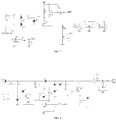
- an electric circuit function block diagram of the present invention comprises: a Li battery with its negative electrode connected to the ground, a power source module for voltage reduction connected with a positive electrode of the Li battery, a controller connected with the power source module, a damper controlling mechanism connected with the controller, a throttle controlling mechanism connected with the controller, an electrically-starting controlling mechanism connected with the controller, a high voltage ignition mechanism connected with the controller, a speed feedback mechanism connected with the controller and with a Hall element, and a temperature sensor connected with the controller, wherein the controller is provided therein with a main chip circuit and its electric circuit structure is specifically detailed in FIG. 6 , the inside electric circuit of the power source module is specifically detailed in FIG.
- the high voltage ignition mechanism comprises a voltage boosting device, a spark plug, and other element(s).
- the Li battery is used as the DC power source
- the position sensor is used to detect the rotation speed of the flywheel to determine the ignition angle
- the temperature sensor is used to detect the current temperature
- the controller converts the DC power source from a low voltage to a high voltage via the voltage boosting device.
- the controller according to various working conditions including the current rotation speed, working time, temperature, etc., calculates the currently necessary ignition angle and ignition voltage, then the electronic ignition system, with the angle calculated by the controller itself, uses a high voltage pack to release an electric spark with corresponding energy such that the fuel-gas mixture in the cylinder combusts, pushing the piston to move to and fro so that the gasoline engine is in an ideal working state.
- the temperature sensor is used to detect the current temperature and when the temperature is relatively low, the ignition voltage should be increased.
- the controller can control the ignition angle and energy such that the ignition occurs when the concentration in the cylinder is the highest, producing the largest spark, so that it is relatively easy to start the gasoline engine, easier to operate and higher in efficiency.
- magnet motor in the present invention, it is not necessary to install bulky magnet modules on the blades of the flywheel, and thus the weight of the blades can be reduced, so that the power (from the gasoline engine) consumed by the blades is relatively small and the whole efficiency of the system can be improved.
- the controller with an MCU design can precisely control the ignition angle and energy.
- the controller can, with the flywheel position detected by the position sensor and the flywheel rotation speed and with controlling of the program algorithms, adjust the ignition angle at the appropriate time.
- the controller can, with the flywheel position detected by the position sensor and the flywheel rotation speed and with controlling of the program algorithms, adjust the ignition angle at the appropriate time.
Abstract
Description
- The present invention relates to a portable gasoline tool and an electronic ignition system thereof.
- A portable gasoline tool is often used in the area of garden greening, and its electronic ignition system is a key system therein. The electronic ignition system mainly comprises a flywheel, a voltage boosting device, and a spark plug, and mainly functioning to ignite, with a spark produced by the spark plug driven by a high voltage coil, the combustible gas mixture introduced into the combustion chamber, to make it explode to release energy. In addition, the electronic ignition system operates at a most suitable ignition angle and gives out sufficient ignition voltage such that the gasoline engine of the portable gasoline tool can run smoothly and has an improved efficiency. Currently, the commonly used electronic ignition system comprises a magnet motor, an igniter, an inductive coil provided on the cylinder, and a permanent magnet mounted on the flywheel. The permanent magnet is rotated with the flywheel, and every time it meets the inductive coil fixed on the cylinder around a circle, an inductive current is produced in the inductive coil (as in an electric generator in principle). The higher the rotation speed of the flywheel is, the larger the inductive current is produced; the lower the rotation speed, the smaller the inductive current is. An electric circuit is used to amplify the coil inductive current into a voltage of tens of kV such that the spark plug connected thereto and placed in parallel in the combustion chamber of the gasoline engine, ignites. However, the electronic ignition system has the following defects: the voltage is proportional to the rotation speed, and when the rotation speed is relatively low, the produced inductive current is small and the ignition voltage is relatively low wherein the relation of the ignition time point, the ignition voltage and the rotation speed is shown in
FIG. 1 . Moreover, in the start-up stage, the rotation speed is relatively low, the ignition voltage cannot produce a large spark needed at this time and it is adverse to ignition, resulting in the difficulties to start the gasoline engine for the user to employ. - The technical problem to be solved by the present invention is to provide a portable gasoline tool and an electronic ignition system thereof wherein the operation is simple and convenient, it can be started even if the rotation speed is relatively low in the start-up stage, enabling an enhanced user experience and facilitating popularization and promotion of the product.
- The first technical solution of the present invention is: an electronic ignition system for a portable gasoline tool, comprising a voltage boosting device and a spark plug connected with an output of the voltage boosting device; the electronic ignition system for the portable gasoline tool further comprises a DC power source and a controller electrically connected with the DC power source and connected with the voltage boosting device, wherein the controller controls ignition voltage and an ignition advance angle.
- Based on the first technical solution, the following dependent technical solutions are further included:
The voltage boosting device boosts an output voltage of the DC power source to an ignition voltage; the output voltage of the DC power source is 6 V∼12 V, and the ignition voltage is 10 kV∼30 kV. - The ignition voltage is 15 kV∼30 kV.
- The voltage boosting device comprises a plurality of stages of voltage boosting units; an output voltage of the lithium battery is boosted, through the plurality of stages of voltage boosting units, to the ignition voltage.
- The voltage boosting device comprises a first-stage voltage boosting unit and a second-stage voltage boosting unit, the first-stage voltage boosting unit boosts the voltage from the output voltage of the lithium battery to 200 V∼250 V, and the second-stage voltage boosting unit further boosts the voltage from 200 V∼250 V to the ignition voltage.
- The portable gasoline tool comprises: a body, and a flywheel provided on the body; the electronic ignition system further comprises: a sensing element provided on the flywheel or the body, and a position sensor provided on the body or the flywheel to obtain a rotation speed of the flywheel through the sensing element; the controller controls the ignition voltage and the ignition advance angle according to the rotation speed of the flywheel.
- The sensing element is provided on the flywheel and it is a magnet, with its number being at least one; the position sensor is provided on the body, with its number being one.
- The sensing element is provided on the flywheel and it is Fe, with its number being at least one; the position sensor is provided on the body, with its number being one, wherein the position sensor is an approach switch.
- The DC power source is a Li battery; the controller is an MCU controller.
- The DC power source is removable and rechargeable.
- The electronic ignition system further comprises a temperature sensor connected with the controller, the temperature sensor obtains an ambient temperature; the controller can control the ignition voltage and the ignition advance angle according to the ambient temperature.
- The voltage boosting device comprises an ignition coil.
- The second technical solution of the present invention is: a portable gasoline tool, comprising a body, a cylinder provided in the body, a piston movable to and fro in the cylinder, a crankshaft co-moved with the piston, a flywheel provided on the body and driven by the crankshaft to rotate, and the electronic ignition system described above.
- In the present invention, the controller with an MCU design can precisely control the ignition angle and energy. When the load of the gasoline engine changes rapidly, the controller can, with the change in rotation speed as detected by the position sensor, adjust the ignition angle at the appropriate time, thus making the gasoline engine work more stably. In addition, the operation is simple and convenient, and it can be started even if the rotation speed is relatively low in the start-up stage, thus enabling an enhanced user experience and facilitating popularization and promotion of the product.
-
-
FIG. 1 is a characteristic graph of a traditional ignition system; -
FIG. 2 is a perspective structure diagram of the present invention, with a portion of the housing removed; -
FIG. 3 is a section view ofFIG. 1 ; -
FIG. 4 is an electric circuit function block diagram of the present invention; -
FIG. 5 is a characteristic graph of an ignition system of the present invention; -
FIG. 6 is an electric circuit diagram of a controller of the present invention; -
FIG. 7 is an electric circuit diagram of a power source module of the present invention; -
FIG. 8 is an electric circuit diagram of a high voltage ignition mechanism of the present invention; -
FIG. 9 is an electric circuit diagram of a damper and throttle controlling mechanism of the present invention; and -
FIG. 10 is an electric circuit diagram of an electrically-starting controlling mechanism of the present invention. - Embodiment(s): as shown in
FIGs. 2-3 , in the present invention, a first embodiment of an electronic ignition system for a portable gasoline tool is provided, comprising: a voltage boosting device and aspark plug 40 connected with an output of the voltage boosting device. The electronic ignition system for the portable gasoline tool further comprises a Direct Current (DC)power source 70 and a controller electrically connected with theDC power source 70 and connected with the voltage boosting device. TheDC power source 70 is preferably a Li battery, more preferably a removable rechargeable lithium battery. The controller is a Micro Control Unit (MCU) controller, wherein the controller controls ignition voltage and an ignition advance angle. - As shown in
FIGs. 2-3 for reference, in the present invention, a second embodiment of an electronic ignition system for a portable gasoline tool is provided wherein the portable gasoline tool comprises: abody 10, and aflywheel 30 provided on thebody 10 and drawn manually or electrically. The electronic ignition system for the portable gasoline tool comprises a voltage boosting device and aspark plug 40 connected with an output of the voltage boosting device. The electronic ignition system for the portable gasoline tool further comprises: a sensing element provided on theflywheel 30 or thebody 10, and aposition sensor 50 provided on thebody 10 or theflywheel 30 to obtain a rotation speed of theflywheel 30 through the sensing element, and a controller electrically connected with theposition sensor 50 and connected with the voltage boosting device, wherein the controller controls ignition voltage and an ignition advance angle. In the present embodiment, the sensing element is provided on theflywheel 30 and it is a magnet, with its number being at least two; and theposition sensor 50 is provided on thebody 10, with its number being one. Theposition sensor 50 is preferably a Hall element, or may be a photoelectric element or other elements. - Preferably, the sensing element comprises a
positioning magnet 32 for initial positioning, and ameasuring magnet 34 for rotation speed measurement, wherein thepositioning magnet 32 is also referred as the top dead point positioning magnet. - Preferably, the present embodiment further comprises a Printed Circuit Board (PCB) 52 provided on the
body 10 and electrically connected and fixed with theposition sensor 50. The sensing element is provided in a circumferential direction of theflywheel 30, and the PCB 52 is located at a side of theflywheel 30 and is kept spaced from theflywheel 30. - Preferably, the sensing element is a magnet, with its number being one, and at least two position sensors are provided.
- Preferably, the present embodiment further comprises a
DC power source 70 providing electric energy to the controller. TheDC power source 70 is preferably a Li battery, more preferably a removable lithium battery. - Preferably, the voltage boosting device boosts an output voltage of the Li battery to an ignition voltage, thus providing sufficient energy to ignite the fuel-gas mixture. The output voltage of the Li battery is 6 V∼12 V, and the ignition voltage is 10 kV∼30 kV. Preferably, the voltage boosting device comprises a plurality of stages of voltage boosting units. In the present embodiment, the voltage boosting device comprises a first-stage voltage boosting unit and a second-stage voltage boosting unit, the first-stage voltage boosting unit boosts the voltage from the output voltage of the lithium battery to 200 V∼250 V, and the second-stage voltage boosting unit further boosts the voltage from 220 V∼250 V to the ignition voltage. Specifically in the present embodiment, the output voltage of the lithium battery is 6 V or 7.2 V. The voltage boosting device 241 first boosts the output voltage of the lithium battery to 220 V by a series induction manner, and then boosts the 220 V voltage to the ignition voltage wherein the ignition voltage is 15 kV∼30 kV.
- Preferable, the voltage boosting device comprises an ignition coil.
- As shown in
FIGs. 2-3 for reference, in the present invention, a third embodiment of a portable gasoline tool is provided, comprising: abody 10, acylinder 20 provided in thebody 10, apiston 60 movable to and fro within thecylinder 20, acrankshaft 62 driving thepiston 60 to move, aflywheel 30 provided on thebody 10 and driven by thecrankshaft 62 to rotate, and an electronic ignition system which comprises a voltage boosting device and aspark plug 40 connected with an output of the voltage boosting device and provided on thecylinder 20. The electronic ignition system further comprises: a sensing element provided on theflywheel 30 or thebody 10, aposition sensor 50 provided on thebody 10 or theflywheel 30 to obtain a rotation speed of the flywheel through the sensing element, and a controller electrically connected with theposition sensor 50 and connected with the voltage boosting device. Wherein, the sensing element is preferably provided on theflywheel 30 and it is a magnet, with its number being at least two; and theposition sensor 50 is provided on thebody 10, with its number being one. Theposition sensor 50 is preferably a Hall element, or may be a photoelectric element or other elements. Thecylinder 20 is provided therein with acombustion chamber 22, wherein thespark plug 40 is fixed on thecylinder 20 and is at least partially extended into thecombustion chamber 22. - Preferably, the sensing element comprises a
positioning magnet 32 for initial positioning, and a measuringmagnet 34 for rotation speed measurement, wherein thepositioning magnet 32 is also referred as the top dead point positioning magnet. - Preferably, the present embodiment further comprises a
PCB 52 provided on thebody 10 and electrically connected and fixed with theposition sensor 50. The sensing element is provided in a circumferential direction of theflywheel 30, and thePCB 52 is located at a side of theflywheel 30 and is kept spaced from theflywheel 30. - Preferably, the sensing element is a magnet, with its number being one, and at least two position sensors are provided. The
position sensor 50 is preferably a Hall element, or may be a photoelectric element or other elements. - Preferably, the present embodiment further comprises a
DC power source 70 providing electric energy to the controller, and a temperature sensor connected with the controller. - As shown in
FIGs. 2-3 for reference, in the present invention, a fourth embodiment of an electronic ignition system for a portable gasoline tool is provided, comprising: a voltage boosting device and aspark plug 40 connected with an output of the voltage boosting device. The electronic ignition system for the portable gasoline tool further comprises: aDC power source 70, and a controller electrically connected with theDC power source 70 and connected with the voltage boosting device, and a temperature sensor connected with the controller. TheDC power source 70 is preferably a Li battery, more preferably a removable lithium battery. - As shown in
FIGs. 2-3 for reference, in the present invention, a fifth embodiment of an electronic ignition system for a portable gasoline tool is provided wherein the portable gasoline tool comprises: abody 10, and aflywheel 30 provided on thebody 10 and drawn manually or electrically. The electronic ignition system for the portable gasoline tool comprises a voltage boosting device and aspark plug 40 connected with an output of the voltage boosting device. The electronic ignition system for the portable gasoline tool further comprises: a sensing element provided on theflywheel 30 or thebody 10, aposition sensor 50 provided on thebody 10 or theflywheel 30 to obtain a rotation speed of the flywheel through the sensing element, a controller electrically connected with theposition sensor 50 and connected with the voltage boosting device, aDC power source 70 providing electric energy to the controller, and a temperature sensor connected with the controller. Theposition sensor 50 is preferably a Hall element, or may be a photoelectric element or other elements. TheDC power source 70 is preferably a Li battery, more preferably a removable rechargeable lithium battery. - As shown in
FIG. 4 for reference, an electric circuit function block diagram of the present invention is provided, and in structure it comprises: a Li battery with its negative electrode connected to the ground, a power source module for voltage reduction connected with a positive electrode of the Li battery, a controller connected with the power source module, a damper controlling mechanism connected with the controller, a throttle controlling mechanism connected with the controller, an electrically-starting controlling mechanism connected with the controller, a high voltage ignition mechanism connected with the controller, a speed feedback mechanism connected with the controller and with a Hall element, and a temperature sensor connected with the controller, wherein the controller is provided therein with a main chip circuit and its electric circuit structure is specifically detailed inFIG. 6 , the inside electric circuit of the power source module is specifically detailed inFIG. 7 , the electric circuit structure of the high voltage ignition mechanism is specifically detailed inFIG. 8 , the electric circuit structure of the damper and throttle controlling mechanism is specifically detailed inFIG. 9 , and the electric circuit structure of the electrically-starting controlling mechanism is specifically detailed inFIG. 10 . The high voltage ignition mechanism comprises a voltage boosting device, a spark plug, and other element(s). - In summary of the above embodiments, in the present invention, the Li battery is used as the DC power source, the position sensor is used to detect the rotation speed of the flywheel to determine the ignition angle, the temperature sensor is used to detect the current temperature, the controller converts the DC power source from a low voltage to a high voltage via the voltage boosting device. The controller, according to various working conditions including the current rotation speed, working time, temperature, etc., calculates the currently necessary ignition angle and ignition voltage, then the electronic ignition system, with the angle calculated by the controller itself, uses a high voltage pack to release an electric spark with corresponding energy such that the fuel-gas mixture in the cylinder combusts, pushing the piston to move to and fro so that the gasoline engine is in an ideal working state. Therefore, ignition can be achieved at a very low rotation speed. The temperature sensor is used to detect the current temperature and when the temperature is relatively low, the ignition voltage should be increased. Also, the controller can control the ignition angle and energy such that the ignition occurs when the concentration in the cylinder is the highest, producing the largest spark, so that it is relatively easy to start the gasoline engine, easier to operate and higher in efficiency. Compared with the prior technical solution of magnet motor, in the present invention, it is not necessary to install bulky magnet modules on the blades of the flywheel, and thus the weight of the blades can be reduced, so that the power (from the gasoline engine) consumed by the blades is relatively small and the whole efficiency of the system can be improved. Also, by speed detection, the ignition angles at different speeds can be controlled to be in the ideal state, thus improving the working efficiency of the gasoline engine system in any speed state. Moreover, the controller with an MCU design can precisely control the ignition angle and energy. When the load of the gasoline engine changes rapidly, the controller can, with the flywheel position detected by the position sensor and the flywheel rotation speed and with controlling of the program algorithms, adjust the ignition angle at the appropriate time. Thus a relation of the ignition time point, the ignition voltage and the rotation speed as obtained is shown in
FIG. 5 , thus making the gasoline engine work more stably. - Certainly, the above embodiments are provided only to explain the technical concepts and features of the present invention, with the purpose for enabling those skilled in the art to implement the present invention by understanding the contents thereof, rather than limiting the protection scope of the present invention thereto. Any equivalent alternative or modification made to the main technical solutions of the present invention based on the substantial spirit of the present invention will fall within the protection scope of the present invention.
Claims (10)
- An electronic ignition system for a portable gasoline tool, comprising: a voltage boosting device and a spark plug connected with an output of the voltage boosting device, wherein the electronic ignition system for the portable gasoline tool further comprises a DC power source and a controller electrically connected with the DC power source and connected with the voltage boosting device, wherein the controller controls ignition voltage and an ignition advance angle.
- The garden tool according to claim 1, wherein the voltage boosting device boosts an output voltage of the DC power source to an ignition voltage; the output voltage of the DC power source is 6 V∼12 V, and the ignition voltage is 10 kV∼30 kV.
- The garden tool according to claim 2, wherein the ignition voltage is 15 kV∼30 kV.
- The garden tool according to any one of claims 1-3, wherein the voltage boosting device comprises a plurality of stages of voltage boosting units; an output voltage of the lithium battery is boosted to the ignition voltage through the plurality of stages of voltage boosting units.
- The garden tool according to claim 4, wherein the voltage boosting device comprises a first-stage voltage boosting unit and a second-stage voltage boosting unit, the first-stage voltage boosting unit boosts a voltage from the output voltage of the lithium battery to 200 V∼250 V, and the second-stage voltage boosting unit further boosts the voltage from 200 V∼250 V to the ignition voltage.
- The electronic ignition system for the portable gasoline tool according to claim 1, wherein the portable gasoline tool comprises: a body, and a flywheel provided on the body; the electronic ignition system further comprises: a sensing element provided on the flywheel or the body, and a position sensor provided on the body or the flywheel to obtain a rotation speed of the flywheel through the sensing element; the controller controls the ignition voltage and the ignition advance angle according to the rotation speed of the flywheel.
- The electronic ignition system for the portable gasoline tool according to claim 1, wherein the DC power source is a removable rechargeable Li battery; the controller is an MCU controller.
- The electronic ignition system for the portable gasoline tool according to claim 1, wherein the electronic ignition system further comprises a temperature sensor connected with the controller, and the temperature sensor obtains an ambient temperature; the controller can control the ignition voltage and the ignition advance angle according to the ambient temperature.
- The electronic ignition system for the portable gasoline tool according to claim 1, wherein the voltage boosting device comprises an ignition coil.
- A portable gasoline tool, comprising: a body, a cylinder provided in the body, a piston movable to and fro within the cylinder, a crankshaft co-moved with the piston, a flywheel provided on the body and driven by the crankshaft to rotate, and the electronic ignition system according to any one of claims 1-8.
Applications Claiming Priority (2)
| Application Number | Priority Date | Filing Date | Title |
|---|---|---|---|
| CN201610024698.XA CN105508117A (en) | 2016-01-15 | 2016-01-15 | Portable gasoline tool and electronic ignition system thereof |
| PCT/CN2017/071178 WO2017121398A1 (en) | 2016-01-15 | 2017-01-13 | Portable gasoline tool and electronic ignition system thereof |
Publications (2)
| Publication Number | Publication Date |
|---|---|
| EP3404251A1 true EP3404251A1 (en) | 2018-11-21 |
| EP3404251A4 EP3404251A4 (en) | 2019-02-13 |
Family
ID=55716347
Family Applications (1)
| Application Number | Title | Priority Date | Filing Date |
|---|---|---|---|
| EP17738211.6A Pending EP3404251A4 (en) | 2016-01-15 | 2017-01-13 | Portable gasoline tool and electronic ignition system thereof |
Country Status (4)
| Country | Link |
|---|---|
| US (1) | US10704521B2 (en) |
| EP (1) | EP3404251A4 (en) |
| CN (1) | CN105508117A (en) |
| WO (1) | WO2017121398A1 (en) |
Families Citing this family (3)
| Publication number | Priority date | Publication date | Assignee | Title |
|---|---|---|---|---|
| EP3404239B1 (en) | 2016-01-15 | 2024-05-01 | Suzhou Cleva Precision Machinery & Technology Co., Ltd. | Garden tool |
| CN105508117A (en) * | 2016-01-15 | 2016-04-20 | 苏州科瓴精密机械科技有限公司 | Portable gasoline tool and electronic ignition system thereof |
| CN108757265B (en) * | 2018-07-09 | 2024-01-05 | 苏州科瓴精密机械科技有限公司 | Engine starting circuit |
Family Cites Families (37)
| Publication number | Priority date | Publication date | Assignee | Title |
|---|---|---|---|---|
| EP0069889B1 (en) * | 1981-07-03 | 1988-05-11 | Nissan Motor Co., Ltd. | Ignition system for an internal combustion engine |
| JPS62107272A (en) * | 1985-10-31 | 1987-05-18 | Nippon Soken Inc | Ignition device for internal combustion engine |
| CN1028890C (en) * | 1992-06-16 | 1995-06-14 | 姜林 | Energy-storage starter on vehicles |
| IT1275771B1 (en) * | 1995-06-21 | 1997-10-17 | Ducati Energia Spa | ELECTRONIC IGNITION SYSTEM WITH MICRO-CONTROLLER FOR INVERTIBLE INTERNAL COMBUSTION ENGINES |
| JP3410294B2 (en) * | 1996-06-21 | 2003-05-26 | 三菱電機株式会社 | Knock control device for internal combustion engine |
| JP3799898B2 (en) * | 1999-09-20 | 2006-07-19 | 株式会社日立製作所 | In-cylinder injection engine control device |
| JP3827059B2 (en) | 2000-07-11 | 2006-09-27 | 本田技研工業株式会社 | Engine start control device |
| JP4270426B2 (en) | 2001-01-31 | 2009-06-03 | スターテング工業株式会社 | Engine starter |
| JP4199688B2 (en) * | 2004-03-18 | 2008-12-17 | 本田技研工業株式会社 | Auto choke device |
| US7525287B2 (en) | 2004-10-08 | 2009-04-28 | Husqvarna Zenoah Co., Ltd. | Battery pack for driving electric motor of compact engine starting device, engine starting device driven by the battery pack, and manual working machine having the engine starting device |
| DE102006038277B4 (en) * | 2006-08-16 | 2021-01-21 | Andreas Stihl Ag & Co. Kg | Method for regulating the composition of a fuel / air mixture for an internal combustion engine |
| JP4868523B2 (en) | 2007-04-04 | 2012-02-01 | 京都電機器株式会社 | Auto choke device in engine |
| JP2009185695A (en) * | 2008-02-06 | 2009-08-20 | Walbro Japan Inc | Layered scavenging carburetor |
| US8434444B2 (en) * | 2008-05-27 | 2013-05-07 | Briggs & Stratton Corporation | Engine with an automatic choke and method of operating an automatic choke for an engine |
| JP4497238B2 (en) * | 2008-09-16 | 2010-07-07 | トヨタ自動車株式会社 | Vehicle control system |
| CN101363380A (en) | 2008-10-09 | 2009-02-11 | 张和君 | Electric-controlled petrol engine work system |
| JP5256151B2 (en) | 2009-09-02 | 2013-08-07 | 株式会社マキタ | Brush cutter |
| DE102009053236A1 (en) * | 2009-11-06 | 2011-05-12 | Andreas Stihl Ag & Co. Kg | Hand-held implement with an air-cooled internal combustion engine |
| EP2693019B1 (en) * | 2011-03-31 | 2017-04-05 | Makita Corporation | Mobile operating machine having hybrid driving system |
| CN202047923U (en) * | 2011-05-27 | 2011-11-23 | 山东绿环动力设备有限公司 | Control system for four-cylinder gas engine |
| DE102012012798B4 (en) | 2012-06-28 | 2014-11-13 | Andreas Stihl Ag & Co. Kg | Working device with a braking device |
| US10161376B2 (en) | 2013-05-24 | 2018-12-25 | Denso Corporation | Ignition control apparatus |
| CN103758671A (en) * | 2014-01-14 | 2014-04-30 | 曲日 | Noiseless starting gasoline engine and starting method thereof |
| CN204253214U (en) * | 2014-10-31 | 2015-04-08 | 白树春 | Be applicable to the automatic throttle device that common motorcycle carburetor uses |
| CN205370829U (en) * | 2016-01-15 | 2016-07-06 | 苏州科瓴精密机械科技有限公司 | Portable petrol instrument |
| CN105673290B (en) * | 2016-01-15 | 2018-11-09 | 苏州科瓴精密机械科技有限公司 | Portable gasoline tool |
| CN105484899B (en) | 2016-01-15 | 2018-09-18 | 苏州科瓴精密机械科技有限公司 | Portable gasoline engine and its self closing door control system |
| CN205638760U (en) * | 2016-01-15 | 2016-10-12 | 苏州科瓴精密机械科技有限公司 | Mini gasoline engine |
| CN205638761U (en) * | 2016-01-15 | 2016-10-12 | 苏州科瓴精密机械科技有限公司 | Portable gasoline instrument |
| EP3404239B1 (en) * | 2016-01-15 | 2024-05-01 | Suzhou Cleva Precision Machinery & Technology Co., Ltd. | Garden tool |
| CN105545562A (en) * | 2016-01-15 | 2016-05-04 | 苏州科瓴精密机械科技有限公司 | Small gasoline engine |
| CN205638728U (en) | 2016-01-15 | 2016-10-12 | 苏州科瓴精密机械科技有限公司 | Portable gasoline machine and automatic ventilation door control system thereof |
| CN205638762U (en) * | 2016-01-15 | 2016-10-12 | 苏州科瓴精密机械科技有限公司 | Portable gasoline instrument and electronic ignition system thereof |
| CN105484876A (en) | 2016-01-15 | 2016-04-13 | 苏州科瓴精密机械科技有限公司 | Electric accelerator device and control system thereof |
| CN105464875B (en) * | 2016-01-15 | 2019-04-05 | 苏州科瓴精密机械科技有限公司 | Portable gasoline tool |
| CN205503286U (en) | 2016-01-15 | 2016-08-24 | 苏州科瓴精密机械科技有限公司 | Electronic throttle device and control system thereof |
| CN105508117A (en) * | 2016-01-15 | 2016-04-20 | 苏州科瓴精密机械科技有限公司 | Portable gasoline tool and electronic ignition system thereof |
-
2016
- 2016-01-15 CN CN201610024698.XA patent/CN105508117A/en active Pending
-
2017
- 2017-01-13 WO PCT/CN2017/071178 patent/WO2017121398A1/en active Application Filing
- 2017-01-13 US US16/069,557 patent/US10704521B2/en active Active
- 2017-01-13 EP EP17738211.6A patent/EP3404251A4/en active Pending
Also Published As
| Publication number | Publication date |
|---|---|
| US20190024620A1 (en) | 2019-01-24 |
| WO2017121398A1 (en) | 2017-07-20 |
| US10704521B2 (en) | 2020-07-07 |
| EP3404251A4 (en) | 2019-02-13 |
| CN105508117A (en) | 2016-04-20 |
Similar Documents
| Publication | Publication Date | Title |
|---|---|---|
| US10704521B2 (en) | Portable gasoline tool and electronic ignition system thereof | |
| US11909251B2 (en) | Portable propane-fueled battery charger | |
| US20150316018A1 (en) | Capacitive Igniter with a Flameout Time-delay Function | |
| CN205638762U (en) | Portable gasoline instrument and electronic ignition system thereof | |
| CN105509093A (en) | Low-power-consumption intelligent arc lighter and ignition method | |
| CN106150826A (en) | A kind of repeatedly high-energy ignition system based on ion current closed loop control | |
| MXPA05009588A (en) | Power supply for vehicle. | |
| CN203347928U (en) | Small engine electronic control unit with igniting function | |
| CN207830025U (en) | Adaptive motorcycle ignition circuit | |
| CN201837503U (en) | Automobile engine knocking sensor test stand and motor control circuit | |
| CN106321325B (en) | Ignition method and device capable of adjusting ignition time according to temperature | |
| CN201687634U (en) | Automobile multifunctional coordinator | |
| JPS5720559A (en) | Noncontact igniter for internal combustion engine | |
| CN205876584U (en) | A lot of high energy ignition system based on ionic current closed -loop control | |
| JPS5566659A (en) | Ignition device for internal combustion engine | |
| CN205779410U (en) | Battery bag starts and ignition engine | |
| CN215672522U (en) | Integrated igniter | |
| CN212154982U (en) | Electric control carburetor for small fuel engine | |
| CN202157890U (en) | Ignition device of motorcycle | |
| CN212429072U (en) | Integrated igniter for gasoline engine | |
| CN101893514A (en) | Experiment bench with knock sensor for automobile engine and motor control circuit | |
| CN207018135U (en) | A kind of capacitive discharge ignition device | |
| CN106438156B (en) | A kind of timing of engine flameout control circuit | |
| CN202927877U (en) | High-effect electronic igniter | |
| CN202007733U (en) | Alternating-current and direct-current dual-purpose igniter |
Legal Events
| Date | Code | Title | Description |
|---|---|---|---|
| STAA | Information on the status of an ep patent application or granted ep patent |
Free format text: STATUS: THE INTERNATIONAL PUBLICATION HAS BEEN MADE |
|
| PUAI | Public reference made under article 153(3) epc to a published international application that has entered the european phase |
Free format text: ORIGINAL CODE: 0009012 |
|
| STAA | Information on the status of an ep patent application or granted ep patent |
Free format text: STATUS: REQUEST FOR EXAMINATION WAS MADE |
|
| 17P | Request for examination filed |
Effective date: 20180806 |
|
| AK | Designated contracting states |
Kind code of ref document: A1 Designated state(s): AL AT BE BG CH CY CZ DE DK EE ES FI FR GB GR HR HU IE IS IT LI LT LU LV MC MK MT NL NO PL PT RO RS SE SI SK SM TR |
|
| AX | Request for extension of the european patent |
Extension state: BA ME |
|
| A4 | Supplementary search report drawn up and despatched |
Effective date: 20190110 |
|
| RIC1 | Information provided on ipc code assigned before grant |
Ipc: F02P 5/15 20060101ALI20190104BHEP Ipc: F02N 11/08 20060101AFI20190104BHEP Ipc: F02P 5/00 20060101ALI20190104BHEP |
|
| STAA | Information on the status of an ep patent application or granted ep patent |
Free format text: STATUS: REQUEST FOR EXAMINATION WAS MADE |
|
| DAV | Request for validation of the european patent (deleted) | ||
| DAX | Request for extension of the european patent (deleted) | ||
| STAA | Information on the status of an ep patent application or granted ep patent |
Free format text: STATUS: EXAMINATION IS IN PROGRESS |
|
| 17Q | First examination report despatched |
Effective date: 20220117 |