EP3403889B1 - Adaptateur destiné à relier un balai d'essuyage à un bras d'entrainement d'un système d'essuyage - Google Patents
Adaptateur destiné à relier un balai d'essuyage à un bras d'entrainement d'un système d'essuyage Download PDFInfo
- Publication number
- EP3403889B1 EP3403889B1 EP18171486.6A EP18171486A EP3403889B1 EP 3403889 B1 EP3403889 B1 EP 3403889B1 EP 18171486 A EP18171486 A EP 18171486A EP 3403889 B1 EP3403889 B1 EP 3403889B1
- Authority
- EP
- European Patent Office
- Prior art keywords
- adapter
- drive arm
- flexible tongue
- foot
- wiper blade
- Prior art date
- Legal status (The legal status is an assumption and is not a legal conclusion. Google has not performed a legal analysis and makes no representation as to the accuracy of the status listed.)
- Active
Links
Images

Classifications
-
- B—PERFORMING OPERATIONS; TRANSPORTING
- B60—VEHICLES IN GENERAL
- B60S—SERVICING, CLEANING, REPAIRING, SUPPORTING, LIFTING, OR MANOEUVRING OF VEHICLES, NOT OTHERWISE PROVIDED FOR
- B60S1/00—Cleaning of vehicles
- B60S1/02—Cleaning windscreens, windows or optical devices
- B60S1/04—Wipers or the like, e.g. scrapers
- B60S1/32—Wipers or the like, e.g. scrapers characterised by constructional features of wiper blade arms or blades
- B60S1/38—Wiper blades
- B60S1/3848—Flat-type wiper blade, i.e. without harness
- B60S1/3849—Connectors therefor; Connection to wiper arm; Attached to blade
-
- B—PERFORMING OPERATIONS; TRANSPORTING
- B60—VEHICLES IN GENERAL
- B60S—SERVICING, CLEANING, REPAIRING, SUPPORTING, LIFTING, OR MANOEUVRING OF VEHICLES, NOT OTHERWISE PROVIDED FOR
- B60S1/00—Cleaning of vehicles
- B60S1/02—Cleaning windscreens, windows or optical devices
- B60S1/04—Wipers or the like, e.g. scrapers
- B60S1/32—Wipers or the like, e.g. scrapers characterised by constructional features of wiper blade arms or blades
- B60S1/40—Connections between blades and arms
- B60S1/4038—Connections between blades and arms for arms provided with a channel-shaped end
- B60S1/4045—Connections between blades and arms for arms provided with a channel-shaped end comprising a detachable intermediate element mounted on the channel-shaped end
- B60S1/4048—Connections between blades and arms for arms provided with a channel-shaped end comprising a detachable intermediate element mounted on the channel-shaped end the element being provided with retention means co-operating with the channel-shaped end of the arm
-
- B—PERFORMING OPERATIONS; TRANSPORTING
- B60—VEHICLES IN GENERAL
- B60S—SERVICING, CLEANING, REPAIRING, SUPPORTING, LIFTING, OR MANOEUVRING OF VEHICLES, NOT OTHERWISE PROVIDED FOR
- B60S1/00—Cleaning of vehicles
- B60S1/02—Cleaning windscreens, windows or optical devices
- B60S1/04—Wipers or the like, e.g. scrapers
- B60S1/32—Wipers or the like, e.g. scrapers characterised by constructional features of wiper blade arms or blades
- B60S1/40—Connections between blades and arms
- B60S1/4006—Connections between blades and arms for arms provided with a hook-shaped end
-
- B—PERFORMING OPERATIONS; TRANSPORTING
- B60—VEHICLES IN GENERAL
- B60S—SERVICING, CLEANING, REPAIRING, SUPPORTING, LIFTING, OR MANOEUVRING OF VEHICLES, NOT OTHERWISE PROVIDED FOR
- B60S1/00—Cleaning of vehicles
- B60S1/02—Cleaning windscreens, windows or optical devices
- B60S1/04—Wipers or the like, e.g. scrapers
- B60S1/32—Wipers or the like, e.g. scrapers characterised by constructional features of wiper blade arms or blades
- B60S1/40—Connections between blades and arms
- B60S1/4038—Connections between blades and arms for arms provided with a channel-shaped end
- B60S1/4045—Connections between blades and arms for arms provided with a channel-shaped end comprising a detachable intermediate element mounted on the channel-shaped end
- B60S1/4048—Connections between blades and arms for arms provided with a channel-shaped end comprising a detachable intermediate element mounted on the channel-shaped end the element being provided with retention means co-operating with the channel-shaped end of the arm
- B60S2001/4051—Connections between blades and arms for arms provided with a channel-shaped end comprising a detachable intermediate element mounted on the channel-shaped end the element being provided with retention means co-operating with the channel-shaped end of the arm the intermediate element engaging the side walls of the arm
-
- B—PERFORMING OPERATIONS; TRANSPORTING
- B60—VEHICLES IN GENERAL
- B60S—SERVICING, CLEANING, REPAIRING, SUPPORTING, LIFTING, OR MANOEUVRING OF VEHICLES, NOT OTHERWISE PROVIDED FOR
- B60S1/00—Cleaning of vehicles
- B60S1/02—Cleaning windscreens, windows or optical devices
- B60S1/04—Wipers or the like, e.g. scrapers
- B60S1/32—Wipers or the like, e.g. scrapers characterised by constructional features of wiper blade arms or blades
- B60S1/40—Connections between blades and arms
- B60S1/4038—Connections between blades and arms for arms provided with a channel-shaped end
- B60S1/4045—Connections between blades and arms for arms provided with a channel-shaped end comprising a detachable intermediate element mounted on the channel-shaped end
- B60S1/4048—Connections between blades and arms for arms provided with a channel-shaped end comprising a detachable intermediate element mounted on the channel-shaped end the element being provided with retention means co-operating with the channel-shaped end of the arm
- B60S2001/4054—Connections between blades and arms for arms provided with a channel-shaped end comprising a detachable intermediate element mounted on the channel-shaped end the element being provided with retention means co-operating with the channel-shaped end of the arm the intermediate element engaging the back part of the arm
-
- B—PERFORMING OPERATIONS; TRANSPORTING
- B60—VEHICLES IN GENERAL
- B60S—SERVICING, CLEANING, REPAIRING, SUPPORTING, LIFTING, OR MANOEUVRING OF VEHICLES, NOT OTHERWISE PROVIDED FOR
- B60S1/00—Cleaning of vehicles
- B60S1/02—Cleaning windscreens, windows or optical devices
- B60S1/04—Wipers or the like, e.g. scrapers
- B60S1/32—Wipers or the like, e.g. scrapers characterised by constructional features of wiper blade arms or blades
- B60S1/40—Connections between blades and arms
- B60S2001/4093—Connections between blades and arms characterised by the mounting of the pivot on the main yoke of the blade
Definitions
- the present invention relates to wiping systems for a motor vehicle, and more particularly relates to an adapter constituting a device for connecting such a wiping system.
- windshield wipers Conventionly comprise elongated blades, carrying scraper blades made of an elastic material, driven in motion by a drive arm to which they are attached by an appropriate connection device.
- the drive arm is itself connected to a drive device which moves it in an angular reciprocating motion. The scraper blades rub against the glass surface and evacuate water and dirt, bringing them out of the driver's field of vision.
- connection device conventionally comprises a connector and an adapter which connect the wiper blade to the drive arm while allowing a degree of freedom in rotation between these components.
- the connection device also ensures removable wiper blade and drive arm, so as to be able to replace the wiper blade when the latter is worn.
- this adapter conventionally comprises a flexible tab from which emerges a button configured to lock the adapter in the drive arm.
- this flexible tongue may break, the adapter then no longer being able to fulfill its function of connection with the drive arm.
- DE-A-102011053090 shows the preamble of claim 1.
- the object of the invention is to limit the risk of breakage when changing these wiper blades by providing an adapter for a connection device comprising a device making it possible to avoid the risk of over-rotation.
- the button has at least one retainer configured to limit movement of the adapter along a direction perpendicular to a plane in which the material bridge is inscribed, and the adapter comprises a device. limitation of a rotation of the flexible tab relative to the rear part of the adapter.
- the button of the flexible tongue blocks the translational movements along the longitudinal axis, and the retaining member makes it possible to block the movements of the adapter in the direction perpendicular to the material bridge.
- This retaining member defines, with the button from which it comes and with the flexible tongue, a receiving zone configured to receive an edge of the end part of the drive arm.
- the retainer extends in a direction parallel to the longitudinal axis, from the button and towards the body of the adapter.
- the device for limiting the rotation of the flexible tongue relative to the rear part of the adapter comprises at least one tab which bears on the rear part of the adapter.
- the flexible tongue extends mainly in an extension plane in which the longitudinal axis is inscribed.
- the tab extends mainly along a vertical axis, this vertical axis being perpendicular to the extension plane of the flexible tongue.
- the button of the flexible tongue also extends along the vertical axis of the tab, this button therefore extending perpendicularly to the flexible tongue from which it originates.
- the tab is made from one material at least with the button.
- the tab extends in the extension of the button, therefore perpendicular to the flexible tab, this tab and this button extending in opposite directions along the vertical axis.
- the tab can also be partially made from material with the flexible tab.
- the tab has an L-shape, this tab comprising a small branch and a large branch.
- the large side of this tab can for example come from the button of the flexible tongue and the small branch rest on the rear part of the adapter.
- the rear part comprises at least one side panel issuing from a side of the body of the adapter.
- the device for limiting the rotation comprises a single tab which emerges from the button of the adapter by its large branch and the small branch of which bears on a lower edge of the side panel of the rear part.
- the lower edge is located opposite an upper face of the adapter, in which the flexible tongue extends, relative to the longitudinal axis.
- the rear part of the adapter may comprise two side panels respectively coming from each of the sides of the body of the adapter and a bottom wall connecting these two side panels.
- This rear part can then surround, at least partially, the button and the device for limiting the rotation.
- the tab emerges from the button of the flexible tongue via its large branch and the small branch of this tab is supported on a lower edge of the bottom wall of the rear part.
- the device for limiting the rotation of the flexible tongue with respect to the rear part of the adapter comprises two tabs.
- each of the tabs emerges from the button via its large branch and rests on the rear part thanks to its small branch.
- each tab can bear either on the lower edge of the bottom wall of the rear part, or on the lower edge of one of the side panels of this rear part.
- the head of the adapter has at least one lug issuing from a shoulder joining the head and the body, this lug being configured to be received in a hearing provided in the end part of the arm of the lug. training.
- At least one external face of one of the sides of the body comprises at least one crank pin configured to be received in a louver formed in the end part of the drive arm.
- the ear of the drive arm may have a "U" shape capable of receiving both the ear of the head of the adapter and the crankpin of the body of this adapter.
- the crankpin and the lug of the adapter are aligned along the longitudinal axis of the adapter.
- the invention also relates to a wiper blade comprising at least one adapter according to the present invention.
- the invention also relates to a wiping system comprising a wiper blade according to the present invention and a drive arm, an end part of which has two side walls and an upper wall, a louver being provided in each of the side walls, each of which is provided. gills being configured to cooperate with an ear and / or a crank pin of the adapter and the upper wall of the end part being provided with an orifice intended to receive the button of the adapter, one edge of this orifice being interposed between the retainer and the flexible tab.
- At least one of the edges of the orifice formed in the upper wall of the end part of the drive arm is thus received in the reception zone delimited by the retaining member, by the button from which it comes and by the flexible tab from which this button emerges.
- the retaining member bears on the edge of the orifice formed in the upper wall and in which the button of the flexible tongue is inserted, thus ensuring locking of the adapter in the vertical direction.
- the end part of the drive arm may have a clear "U” shaped space configured to receive the adapter, the sides of this "U” shape corresponding to the side walls of the end part and the side walls of the end part. base of this "U” shape corresponding to the upper wall of this end part.
- the side walls of the end part of the drive arm cover the sides of the body of the adapter and that the upper wall of this end part covers at least the material bridge of this body as well as the flexible tongue. of the adapter.
- each of the side walls of the end part of the drive arm has an end ridge which fits in a plane parallel to the upper wall of this end part.
- the longitudinal or transverse names refer to the orientation of an adapter of a wiping system.
- the longitudinal direction corresponds to a direction of longitudinal extension of the adapter, this longitudinal direction being parallel to an axis Ox of an orthonormal frame for example shown in figure 1 .
- a transverse direction corresponds to a direction parallel to an axis Oy of this orthonormal frame, the axis Oy being perpendicular to the axis Ox.
- a vertical direction corresponds to a direction parallel to an axis Oz of the orthonormal coordinate system, the axis Oz being perpendicular to the axis Ox and to the axis Oy.
- transverse sections mentioned below are made according to section planes in which the axes Oy and Oz of the orthonormal coordinate system are inscribed, and the sections Longitudinal are for their part produced according to a section plane in which are inscribed the axes Ox and Oz of this orthonormal frame.
- a motor vehicle is commonly equipped with a wiping system 100 for removing water and / or dirt present on a glazed surface 1, in particular a rear window or a motor vehicle windshield.
- the wiping system 100 comprises a drive arm 2 able to perform an angular reciprocating movement along and over the glazed surface 1.
- the drive bottom 2 may include a driver 3 loaded with 'ensure a mechanical connection between the drive arm 2 and a drive shaft (not shown) in rotation of the drive arm 2.
- the wiping system 100 also comprises a wiper blade 4 which extends along a longitudinal axis, parallel to the axis Ox, called the longitudinal axis X.
- the wiper blade 4 comprises at least one air deflector 5 and a scraper blade 6 connected to one another by a structural element 7 of the wiper blade 4, the latter then being devoid of lifting beams.
- a structural element 7 can for example be formed by a single flexion member, or by a plurality of flexion members or else by a support in which one or more flexion members are threaded.
- the air deflector 5 is designed to transform a pressure applied by a flow of air circulating along the glazed surface 1 into a force for pressing the wiper blade 4 against the glazed surface 1 of the motor vehicle.
- the scraper blade 6 is the part of the wiper blade 4 in direct contact with the glazed surface 1 and it is configured to evacuate the water and / or the dirt present on the latter.
- the air deflector 5, the scraper blade 6 and the structural element 7 form a semi-rigid assembly carried by a connection device 8, interposed between the drive arm 2 and the wiper blade 4.
- this connection device 8 comprises an adapter and a connector, the connector being connected on the one hand to the wiper blade 4 and on the other hand to the adapter, and the adapter being connected both to the connector and to the adapter. to an end part 11 of the driving arm 2.
- connection device 8 thus provides a mechanical connection between the end part 11 of the drive arm 2 and the wiper blade 4.
- This connection device 8 also makes it possible to separate the wiper blade 4 from the drive arm 2. , with a view to replacing the wiper blade 4.
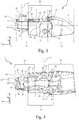
- connection device 8 of the present invention comprising the adapter 9 and the connector 10, where the adapter 9 is the part which fits into the end part 11 of the drive arm 2, this end part 11 also being shown on this figure 2 .
- the connection device 8 extends along the longitudinal axis X.
- the connector 10 comprises an upper part, called the pivot support 12 and a lower part, called the base 13.
- the designations “lower” and “upper” should be understood with reference to the end part 11 of the drive arm, in that sense that this end part 11 covers an upper part of the connection device 8.
- the pivot support 12 and the base 13 are aligned, along a vertical direction Z, this vertical direction Z being parallel to the axis Oz of the orthonormal coordinate system as represented on figure 2 and therefore perpendicular to the longitudinal axis X of the connection device 8.
- pivot support 12 is responsible for ensuring rotation relative to the adapter 9 and extends into a clear "U" shaped space in the adapter 9, as will be described below. .
- the base 13 takes the form of two hooks which enclose a structural element of the wiper blade, this structural element possibly for example being a bending member as described above.
- an orifice 14 is formed in an upper wall 15 of the end part 11 of the drive arm 2, this orifice 14 being configured to receive a button 16 coming from the adapter 9 and which has a retaining member. 17. As illustrated, this retaining member 17 extends in a direction parallel to the upper wall 15 and is intended to bear against one of the edges 18 delimiting the orifice 14.
- the button 16 allows a first locking of a translation of the adapter 9 along the longitudinal axis X and that the retaining member 17 allows a second locking of the adapter 9 in the vertical direction Z.
- the edges 18 of the orifice 14 serve as a stop for this button 16 and for this retaining member 17.
- connection device 8 maintains a certain degree of freedom in rotation with respect to the end part 11 of the drive arm, in particular in order to allow the wiper blade to be changed when the latter is worn out.
- the invention thus proposes an adapter comprising a device for limiting this rotation in order to prevent the user from damaging his wiping system during this change.
- the adapter according to the present invention is thus suitable for both an initial market and an after-sales market.
- the end part 11 of the drive arm 2 also comprises two side walls 19. Only one of these side walls 19 is visible on the figure. figure 2 but it is understood that the other faces it, these two side walls 19 possibly being symmetrical with respect to the longitudinal axis X.
- An opening 20 is provided in at least one of these side walls 19, this opening 20 having a "U" shape configured to receive a crankpin 21 and an ear 22 coming from the adapter 9. This crankpin 21 and this ear 22 will be more fully described in the remainder of the description.
- crank pin 21 and this lug 22 are configured to cooperate with the hearing 20 provided in the end part 11 of the drive arm and thus make it possible to guide and center the adapter 9 during its assembly in the end part. 11.
- the figures 3 and 4 are perspective views of the adapter 9 according to an exemplary embodiment of the present invention, this adapter 9 being seen from the side on the figure 3 and from below on the figure 4 .
- the adapter 9 extends mainly along the longitudinal axis X and comprises, in order along the longitudinal axis X, a head 23, a body 24 and a rear part 25.
- the longitudinal axis X can form an axis of symmetry of the adapter 9.
- the head 23 forms a first longitudinal end of the adapter 9 and the rear part 25 forms a second longitudinal end of this adapter 9, this first end and this second end being opposite with respect to the body 24 of the adapter 9.
- the body 24 of the adapter 9 is delimited at least by two flanks 26 interconnected at least by a material bridge 27, so as to take a "U" shape, viewed from above. It will then be understood that the base of this U is made by the material bridge 27 and the sides of U are made by upper edges 28 of the sides 26 of the body 24.
- This body 24 also has a "U" -shaped cross section, this cross section being in a plane parallel to the Oyz plane. This "U" shape makes it possible to release a space configured to receive the pivot support 12 of the connector, as previously mentioned.
- the material bridge 27 extends along a main extension plane which defines an upper face of the body 24.
- the adapter 9 comprises at least one crank pin 21 configured to be received in the household ear in the side wall of the end part of the drive arm.
- the crank pin 21 is produced on at least one of the sides 26 of the body, and more particularly on an external face of this side 26, in other words on a face intended to cooperate with the end part of the drive arm described above. above.
- these flanks 26 also each comprise an internal face, opposite to the external face of the corresponding flank 26, and intended to cooperate with the connector of the connection device, and more particularly with the pivot support of this connector.
- the adapter according to the present invention comprises two crank pins 21 respectively provided on each of the flanks 26 of the body 24 of the adapter 9.
- crankpins 21 each have a cylindrical shape and extend in a transverse direction Y, parallel to the axis Oy of the orthonormal reference mark as shown in FIG. figure 4 . These crankpins 21 thus extend in a direction perpendicular to the longitudinal axis X of the adapter 9 and away from the body 24.
- crankpins 21 are configured to facilitate the assembly of the adapter 9 with the end part of the drive arm.
- the adapter 9 also comprises a head 23 which extends longitudinally in the extension of the body 24, along the longitudinal axis X previously defined. As can be seen on the figures 3 and 4 , the head 23 is higher and / or wider than the body 24 of the adapter 9. A shoulder 31 is thus formed which partially covers the outer faces of the sides 26 of the body 24. This shoulder 31 serves as a stop for the end part of the drive arm, at least at one longitudinal end edge of the side walls of this end part coming to rest on it when the adapter 9 is mounted in this end part.
- the head 23 has a cross section, that is to say a section of the head 23 inscribed in a plane parallel to the Oyz plane of the orthonormal frame, in the shape of a “U” which, like for the body 24, makes it possible to free up a space in which the connector participating in the connection device can extend and debate in rotation.
- the adapter 9 further comprises at least one ear 22 intended to be received in the ear provided in the end part of the drive arm.
- This lug 22 extends longitudinally, that is to say along the longitudinal axis X, from the head 23 and encroaching at least partially on the external face of one of the flanks 26 of the body 24.
- L the ear 22 originates on the shoulder 31 and has a curved shape whose the top of the curvature is oriented towards the body 24 of the adapter 9.
- this lug 22 performs a wedging and centering function of the adapter 9 in the end part of the drive arm.
- Such a lug 22 can for example be formed by a single half-disc coming from the head 23 of the adapter 9, as can be seen on the figures 3 and 4 .
- an ear 22 can encroach on one of the flanks 26 of the body 24, or two ears 22 can respectively encroach on each of the flanks 26 of this body 24.
- the adapter 9 comprises a rear part 25 which also extends along the longitudinal axis X, away from the body 24.
- this rear part 25 comprises two side panels 32 interconnected by a bottom wall 33, this rear part 25 thus having a “U” shape, seen from below, as for example shown in FIG. figure 4 .
- Each of the side panels 32 of this rear part 25 emerges from one of the sides 26 of the body 24, these side panels 32 and these sides 26 partially overlapping.
- the rear part 25 of the adapter at least partially surrounds a flexible tongue 34 made integrally with the material bridge 27 of the body 24 and also extending along the longitudinal axis X.
- this flexible tongue 34 is surrounded by 'on the one hand by the "U" shape of the rear part 25, and on the other hand by the material bridge 27 of the body 24, this material bridge 27 thus closing the "U" shape of the rear part 25 .
- the flexible tongue 34 has the button 16 configured to be housed in the orifice made in the upper wall of the end part of the driving arm as described above.
- This button 16 extends mainly along a vertical axis Z ', parallel to the axis Oz of the orthonormal frame of reference, and has the retaining member 17 which extends mainly in a direction parallel to the longitudinal axis X, from the button 16 and towards the body 24 of the adapter 9.
- a device 35 for limiting a rotation of the flexible tongue 34 relative to the rear part 25 also comes, at least in part, from the button 16.
- This device 35 for limiting the rotation of the flexible tongue 34 is configured to prevent excessive rotation - also called “over-rotation” - of this flexible tongue 34, for example when changing the wiper blade, for example. compared to the rear part 25 of the adapter 9. In fact, in the event of over-rotation, the flexible tongue 34 could break, which would then render the adapter 9 unusable.
- the device 35 for limiting the rotation of the flexible tongue 34 comprises two tabs 36 which extend mainly in directions parallel to the vertical axis Z 'along which the button 16 extends, these tabs 36 and this button 16 extending in two opposite directions.
- these tabs 36 come from both the button 16 and the flexible tab 34 carrying this button 16.
- These legs 36 each comprise a large branch 37 and a small branch 38, thus taking an "L" shape.
- these tabs 36 emerge from the button 16 and from the flexible tongue 34 by their large branch 37, their small branch 38 extending towards the outside of the rear part 25, in the transverse direction Y.
- these small branches 38 extend transversely away from the adapter 9.
- the small branches 38 of these tabs 36 are configured to bear respectively against each of the side panels 32 of the rear part 25. More precisely, the small arms 38 of these tabs 36 bear against the lower edges 39 of these panels side 32.
- the flexible tongue 34 is movable with respect to the rear part 25 of the adapter 9.
- the flexible tongue 34 moves, it is understood that its movement is limited by the tabs 36. Indeed, the small branches 38 of these tabs 36 come to rest against the lower edges 39 of the side panels 32 of this rear part 25 which then serve as a stop for these tabs 36. The rotation of this flexible tongue 34 relative to the rear part 25 of the adapter 9 is thus limited, preventing the rupture of this flexible tongue 34.
- the device for limiting the rotation of the flexible tongue comprises a single tab configured to bear on the bottom wall of the rear part of the adapter or on one of the two side panels of this rear part.
- the rear part of the adapter comprises a single side panel emerging from one of the sides of the body of this adapter, the tab (s) then resting against this single side panel.
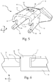
- the figure 5 is a perspective view of the end part 11 of the drive arm, this end part 11 extending mainly along the longitudinal axis X. As described with reference to figure 2 , this end part 11 comprises the top wall 15 from which the two side walls 19 originate. According to a cross section, the end part 11 thus has a profile in the shape of a “U”, each of the side walls 19 ending in an end edge 40.
- each of these end ridges 40 is inscribed in a plane parallel to the upper wall 15.
- the side walls 19 each have a longitudinal end edge 41 intended to bear against the shoulder formed by the covering of the body of the adapter by the head of this adapter.
- a clearance is provided between this shoulder and each of the longitudinal end edges 41 of the end portion 11 of the drive arm.
- the side walls 19 of the end part 11 are also provided with louvers 20, each of these louvers 20 being formed longitudinally from one of the longitudinal end edges 41 of this end part 11. As previously described, each of these louvers.
- gills 20 has a U-shape and is configured to receive both the lug coming from the head of the adapter and the crankpin made on at least one of the outer faces of the sides of the body of this adapter.
- This rotation of the adapter makes it possible to change the wiper blade when it is worn but generates a risk called "over-rotation", that is to say a risk of too great a rotation of the wiper blade.
- 'adapter with respect to the drive arm - and more particularly with respect to the end part 11 of this drive arm - which can damage this adapter and then render it unusable.
- the present invention makes it possible to limit this risk by virtue of the device for limiting the rotation of the flexible tongue relative to the rear part of the adapter.
- the upper wall 15 of this end part 11 for its part comprises the orifice 14 configured to receive the button coming from the flexible tongue of the adapter.
- This orifice 14 has a rectangular shape and is thus delimited by four edges 18. As previously mentioned, at least one of these edges 18 serves as a stop for the retaining member coming from the button.
- the figure 6 is a schematic view of a longitudinal section, that is to say a section taken along a plane parallel to the Oxz plane, made at the orifice 14 formed in the upper wall 15 of the end part 11 of the arm d 'training.
- the flexible tongue 34, the button 16 and the retaining member 17 delimits a reception zone configured to receive at least one of the edges 18 delimiting the orifice 14. It is understood from this figure 6 that the edges 18 of the orifice 14 serve as a stop for both the button 16 and the retaining member 17 of this button 16, thus ensuring the first blocking and the second blocking described above.
- the invention allows a user to change a wiper blade of the wiping system of his vehicle, without risking damaging this wiping system by too much rotation.
- This objective is achieved by means of an adapter comprising a device for limiting the rotation of the flexible tongue with respect to the rear part of this adapter.
- the invention cannot however be limited to the means and configurations described and illustrated.
- the shape and the arrangement of the device limiting the rotation of the flexible tongue with respect to the rear part of the adapter can be modified without harming the invention, insofar as it fulfills the same functionalities as those described in this document.
Landscapes
- Engineering & Computer Science (AREA)
- Mechanical Engineering (AREA)
- Pivots And Pivotal Connections (AREA)
- Brushes (AREA)
- Toys (AREA)
- Cleaning Implements For Floors, Carpets, Furniture, Walls, And The Like (AREA)
Description
- La présente invention se rapporte aux systèmes d'essuyage pour véhicule automobile, et concerne plus particulièrement un adaptateur constitutif d'un dispositif de connexion d'un tel système d'essuyage.
- Les véhicules automobiles sont couramment équipés de système d'essuie-glaces pour assurer un balayage des surfaces vitrées, notamment des pare-brise avant ou lunettes arrière du véhicule, et pour éviter que la vision qu'a le conducteur de son environnement ne soit perturbée. Ces essuie-glaces comportent classiquement des balais allongés, porteurs de lames racleuses réalisées en une matière élastique, entraînés en mouvement par un bras d'entrainement auquel ils sont rattachés par un dispositif de connexion approprié. Le bras d'entrainement est lui-même relié à un dispositif d'entraînement qui le déplace selon un mouvement de va-et-vient angulaire. Les lames racleuses frottent contre la surface vitrée et en évacuent l'eau et les salissures en les amenant en dehors du champ de vision du conducteur.
- Le dispositif de connexion comprend classiquement un connecteur et un adaptateur qui relient le balai d'essuyage au bras d'entraînement en autorisant un degré de liberté en rotation entre ces composants. Le dispositif de connexion assure également une amovibilité entre le balai d'essuyage et le bras d'entraînement, de manière à pouvoir remplacer le balai d'essuyage lorsque celui-ci est usagé.
- Lors du remplacement du balai d'essuyage, l'utilisateur doit effectuer une rotation du balai d'essuyage par rapport au bras d'entrainement. Il existe alors un risque « d'over-rotation », c'est-à-dire un risque de rotation trop importante de ce balai d'essuyage par rapport au bras d'entrainement. L'adaptateur permettant la connexion entre ce balai d'essuyage et ce bras d'entrainement peut être endommagé par une telle « over-rotation ».
- Plus précisément, cet adaptateur comprend classiquement une languette flexible de laquelle émerge un bouton configuré pour bloquer l'adaptateur dans le bras d'entrainement. En cas «d'over-rotation », cette languette flexible peut se casser, l'adaptateur ne pouvant alors plus remplir sa fonction de connexion avec le bras d'entrainement.
DE-A-102011053090 montre le préambule de la revendication 1. - L'invention a pour objectif de limiter le risque de casse lors du changement de ces balais d'essuyage en proposant un adaptateur pour un dispositif de connexion comprenant un dispositif permettant d'éviter le risque d'over-rotation.
- La présente invention concerne ainsi un adaptateur destiné à relier un balai d'essuyage à un bras d'entraînement d'un système d'essuyage pour véhicule automobile, l'adaptateur s'étendant principalement selon un axe longitudinal et comprenant au moins :
- un corps comprenant deux flancs reliés entre eux, au moins en partie, par un pont de matière,
- une tête formant une première extrémité longitudinale de l'adaptateur,
- une partie arrière formant une deuxième extrémité longitudinale de l'adaptateur opposée à la première extrémité longitudinale par rapport au corps,
- une languette flexible issue du corps de l'adaptateur et un bouton émergeant de la languette flexible, ce bouton étant configuré pour bloquer l'adaptateur dans une partie terminale du bras d'entrainement du système d'essuyage.
- Selon la présente invention, le bouton présente au moins un organe de retenue configuré pour limiter un mouvement de l'adaptateur le long d'une direction perpendiculaire à un plan dans lequel s'inscrit le pont de matière, et l'adaptateur comprend un dispositif de limitation d'une rotation de la languette flexible par rapport à la partie arrière de l'adaptateur.
- Le bouton de la languette flexible bloque les mouvements de translation selon l'axe longitudinal, et l'organe de retenue permet de bloquer les mouvements de l'adaptateur selon la direction perpendiculaire au pont de matière.
- Cet organe de retenue délimite, avec le bouton dont il est issu et avec la languette flexible, une zone de réception configurée pour recevoir un bord de la partie terminale du bras d'entrainement.
- L'organe de retenue s'étend selon une direction parallèle à l'axe longitudinal, depuis le bouton et vers le corps de l'adaptateur.
- Selon la présente invention, le dispositif de limitation de la rotation de la languette flexible par rapport à la partie arrière de l'adaptateur comprend au moins une patte qui prend appui sur la partie arrière de l'adaptateur.
- La languette flexible s'étend principalement dans un plan d'extension dans lequel s'inscrit l'axe longitudinal. La patte s'étend principalement selon un axe vertical, cet axe vertical étant perpendiculaire au plan d'extension de la languette flexible. Le bouton de la languette flexible s'étend quant à lui également selon l'axe vertical de la patte, ce bouton s'étendant donc perpendiculairement à la languette flexible dont il est issu.
- Selon une caractéristique de la présente invention, la patte est issue de matière au moins avec le bouton.
- Plus précisément, la patte s'étend dans le prolongement du bouton, donc perpendiculairement à la languette flexible, cette patte et ce bouton s'étendant dans des sens opposés le long de l'axe vertical. La patte peut également être partiellement issue de matière avec la languette flexible.
- Selon l'invention, la patte présente une forme de L, cette patte comprenant une petite branche et une grande branche.
- Le grand coté de cette patte peut par exemple être issu du bouton de la languette flexible et la petite branche s'appuyer sur la partie arrière de l'adaptateur.
- Selon l'invention, la partie arrière comprend au moins un pan latéral issu d'un flanc du corps de l'adaptateur.
- Selon l'invention, le dispositif de limitation de la rotation comprend une seule patte qui émerge du bouton de l'adaptateur par sa grande branche et dont la petite branche prend appui sur un bord inférieur du pan latéral de la partie arrière.
- On comprend que le bord inférieur se situe à l'opposé d'une face supérieure de l'adaptateur, dans laquelle s'étend la languette flexible, par rapport à l'axe longitudinal.
- Selon la présente invention, la partie arrière de l'adaptateur peut comprendre deux pans latéraux respectivement issus de chacun des flancs du corps de l'adaptateur et une paroi de fond reliant ces deux pans latéraux.
- Cette partie arrière peut alors entourer, au moins partiellement, le bouton et le dispositif de limitation de la rotation.
- Selon une variante du premier mode de réalisation, la patte émerge du bouton de la languette flexible par sa grande branche et la petite branche de cette patte prend appui sur un bord inférieur de la paroi de fond de la partie arrière.
- Selon un deuxième mode de réalisation de la présente invention, le dispositif de limitation de la rotation de la languette flexible par rapport à la partie arrière de l'adaptateur comprend deux pattes. Selon ce deuxième mode de réalisation, chacune des pattes émerge du bouton par sa grande branche et prend appui sur la partie arrière grâce à sa petite branche.
- Selon différentes variantes de ce deuxième mode de réalisation, chaque patte peut prendre appui soit sur le bord inférieur de la paroi de fond de la partie arrière, soit sur le bord inférieur de l'un des pans latéraux de cette partie arrière.
- Selon une caractéristique de la présente invention, la tête de l'adaptateur présente au moins une oreille issue d'un épaulement joignant la tête et le corps, cette oreille étant configurée pour être reçue dans une ouïe ménagée dans la partie terminale du bras d'entrainement.
- Selon une caractéristique de la présente invention, au moins une face externe de l'un des flancs du corps comprend au moins un maneton configuré pour être reçu dans une ouïe ménagée dans la partie terminale du bras d'entrainement.
- Selon l'invention, l'ouïe du bras d'entrainement peut présenter une forme de « U » apte à recevoir à la fois l'oreille de la tête de l'adaptateur et le maneton du corps de cet adaptateur. Selon la présente invention, le maneton et l'oreille de l'adaptateur sont alignés le long de l'axe longitudinal de l'adaptateur.
- L'invention concerne également un balai d'essuyage comprenant au moins un adaptateur selon la présente invention.
- L'invention concerne encore un système d'essuyage comprenant un balai d'essuyage selon la présente invention et un bras d'entrainement dont une partie terminale présente deux parois latérales et une paroi supérieure, une ouïe étant ménagée dans chacune des parois latérales, chacune des ouïes étant configurée pour coopérer avec une oreille et/ou un maneton de l'adaptateur et la paroi supérieure de la partie terminale étant pourvue d'un orifice destiné à recevoir le bouton de l'adaptateur, un bord de cet orifice étant interposé entre l'organe de retenue et la languette flexible.
- Au moins l'un des bords de l'orifice ménagé dans la paroi supérieure de la partie terminale du bras d'entrainement est ainsi reçu dans la zone de réception délimitée par l'organe de retenue, par le bouton dont il est issu et par la languette flexible de laquelle émerge ce bouton.
- On comprend donc que l'organe de retenue prend appui sur le bord de l'orifice ménagé dans la paroi supérieure et dans lequel est inséré le bouton de la languette flexible, assurant ainsi un blocage de l'adaptateur selon la direction verticale.
- Selon la présente invention, la partie terminale du bras d'entrainement peut présenter un espace dégagé en forme de « U » configuré pour recevoir l'adaptateur, les flancs de cette forme de « U » correspondant aux parois latérales de la partie terminale et la base de cette forme de « U » correspondant à la paroi supérieure de cette partie terminale.
- Ainsi, on comprend que les parois latérales de la partie terminale du bras d'entrainement recouvrent les flancs du corps de l'adaptateur et que la paroi supérieure de cette partie terminale recouvre au moins le pont de matière de ce corps ainsi que la languette flexible de l'adaptateur.
- Selon la présente invention, chacune des parois latérales de la partie terminale du bras d'entrainement présente une arête terminale qui s'inscrit dans un plan parallèle à la paroi supérieure de cette partie terminale.
- D'autres détails, caractéristiques et avantages ressortiront plus clairement à la lecture de la description détaillée donnée ci-après à titre indicatif, en relation avec les différents modes de réalisation illustrés sur les figures suivantes :
- la
figure 1 est une représentation schématique d'un système d'essuyage selon la présente invention ; - la
figure 2 est une vue en perspective d'un dispositif de connexion du système d'essuyage selon la présente invention ; - la
figure 3 est une vue en perspective d'un adaptateur du dispositif de connexion illustré sur lafigure 2 ; - la
figure 4 est une vue en perspective de dessous de l'adaptateur du dispositif de connexion représenté sur lafigure 2 ; - la
figure 5 est une vue en perspective d'une partie terminale d'un bras d'entrainement d'un système d'essuyage selon la présente invention ; - la
figure 6 est une représentation schématique d'une coupe longitudinale, ici verticale, réalisée au niveau d'une connexion entre l'adaptateur et la partie terminale du bras d'entrainement du système d'essuyage selon la présente invention. - Dans la suite de la description, les dénominations longitudinales ou transversales se réfèrent à l'orientation d'un adaptateur d'un système d'essuyage. La direction longitudinale correspond à une direction d'extension longitudinale de l'adaptateur, cette direction longitudinale étant parallèle à un axe Ox d'un repère orthonormé par exemple représenté à la
figure 1 . Une direction transversale correspond à une direction parallèle à un axe Oy de ce repère orthonormé, l'axe Oy étant perpendiculaire à l'axe Ox. Une direction verticale correspond à une direction parallèle à un axe Oz du repère orthonormé, l'axe Oz étant perpendiculaire à l'axe Ox et à l'axe Oy. - Les coupes transversales mentionnées ci-après sont réalisées selon des plans de coupe dans lesquels s'inscrivent les axes Oy et Oz du repère orthonormé, et les coupes longitudinales sont quant à elles réalisées selon un plan de coupe dans lequel s'inscrivent les axes Ox et Oz de ce repère orthonormé.
- En référence à la
figure 1 , un véhicule automobile est couramment équipé d'un système d'essuyage 100 pour évacuer une eau et/ou des salissures présentes sur une surface vitrée 1, notamment une lunette arrière ou un pare-brise de véhicule automobile. Le système d'essuyage 100 comprend un bras d'entraînement 2 apte à effectuer un mouvement de va-et-vient angulaire le long et au-dessus de la surface vitrée 1. Le bas d'entraînement 2 peut comprendre un entraîneur 3 chargé d'assurer une liaison mécanique entre le bras d'entraînement 2 et un arbre d'entrainement (non représenté) en rotation du bras d'entraînement 2. - Le système d'essuyage 100 comprend aussi un balai d'essuyage 4 qui s'étend selon un axe longitudinal, parallèle à l'axe Ox, dit axe longitudinal X. Le balai d'essuyage 4 comprend au moins un déflecteur d'air 5 et une lame racleuse 6 reliés l'un à l'autre par un élément de structure 7 du balai d'essuyage 4, ce dernier étant alors dépourvu de palonniers. Un tel élément de structure 7 peut par exemple être formé par un unique organe de flexion, ou par une pluralité d'organes de flexion ou encore par un support dans lequel sont enfilés un ou plusieurs organes de flexion.
- Le déflecteur d'air 5 est prévu pour transformer une pression appliquée par un flux d'air circulant le long de la surface vitrée 1 en une force d'appui du balai d'essuyage 4 contre la surface vitrée 1 du véhicule automobile. La lame racleuse 6 est la pièce du balai d'essuyage 4 en contact direct avec la surface vitrée 1 et elle est configurée pour évacuer l'eau et/ou les salissures présentes sur cette dernière. Le déflecteur d'air 5, la lame racleuse 6 et l'élément de structure 7 forment un ensemble semi-rigide porté par un dispositif de connexion 8, interposé entre le bras d'entraînement 2 et le balai d'essuyage 4.
- Classiquement, ce dispositif de connexion 8 comprend un adaptateur et un connecteur, le connecteur étant connecté d'une part au balai d'essuyage 4 et d'autre part à l'adaptateur, et l'adaptateur étant connecté à la fois au connecteur et à une partie terminale 11 du bras d'entrainement 2.
- Le dispositif de connexion 8 assure ainsi une liaison mécanique entre la partie terminale 11 du bras d'entraînement 2 et le balai d'essuyage 4. Ce dispositif de connexion 8 permet également de séparer le balai d'essuyage 4 du bras d'entraînement 2, en vue d'un remplacement du balai d'essuyage 4.
- La
figure 2 illustre le dispositif de connexion 8 de la présente invention comprenant l'adaptateur 9 et le connecteur 10, où l'adaptateur 9 est la pièce qui se loge dans la partie terminale 11 du bras d'entraînement 2, cette partie terminale 11 étant également représentée sur cettefigure 2 . Tel qu'illustré, le dispositif de connexion 8 s'étend selon l'axe longitudinal X. - Le connecteur 10 comprend une partie supérieure, appelée support de pivot 12 et une partie inférieure, appelée embase 13. Les dénominations « inférieure » et « supérieure » doivent s'entendre en référence à la partie terminale 11 du bras d'entrainement, en ce sens que cette partie terminale 11 vient recouvrir une partie supérieure du dispositif de connexion 8. Ainsi, le support de pivot 12 et l'embase 13 sont alignés, le long d'une direction verticale Z, cette direction verticale Z étant parallèle à l'axe Oz du repère orthonormé tel que représenté sur la
figure 2 et donc perpendiculaire à l'axe longitudinal X du dispositif de connexion 8. - On comprend que le support de pivot 12 est chargé d'assurer une rotation par rapport à l'adaptateur 9 et s'étend dans un espace dégagé en forme de « U » dans l'adaptateur 9, tel que cela sera décrit ci-après.
- Selon un exemple de réalisation, l'embase 13 prend la forme de deux crochets qui enserrent un élément de structure du balai d'essuyage, cet élément de structure pouvant par exemple être un organe de flexion tel que précédemment décrit.
- Tel qu'illustré, un orifice 14 est ménagé dans une paroi supérieure 15 de la partie terminale 11 du bras d'entrainement 2, cet orifice 14 étant configuré pour recevoir un bouton 16 issu de l'adaptateur 9 et qui présente un organe de retenue 17. Tel qu'illustré, cet organe de retenue 17 s'étend selon une direction parallèle à la paroi supérieure 15 et est destiné à venir en appui contre l'un des bords 18 délimitant l'orifice 14.
- On comprend que le bouton 16 permet un premier blocage d'une translation de l'adaptateur 9 selon l'axe longitudinal X et que l'organe de retenue 17 permet un deuxième blocage de l'adaptateur 9 selon la direction verticale Z. Tel que cela est visible sur la
figure 2 , les bords 18 de l'orifice 14 servent de butée à ce bouton 16 et à cet organe de retenue 17. - Malgré ces blocages, il est important que le dispositif de connexion 8 conserve un certain degré de liberté en rotation par rapport à la partie terminale 11 du bras d'entrainement, notamment afin de permettre le changement du balai d'essuyage lorsque celui-ci est usé.
- Lors du changement de ce balai d'essuyage, il existe un risque pour l'utilisateur de mal gérer la rotation du balai d'essuyage et d'effectuer une rotation trop importante pouvant alors endommager le dispositif de connexion, et plus particulièrement l'adaptateur de ce dispositif de connexion. L'invention propose ainsi un adaptateur comprenant un dispositif de limitation de cette rotation afin d'éviter à l'utilisateur d'endommager son système d'essuyage lors de ce changement. L'adaptateur selon la présente invention est ainsi adapté à la fois à un marché initial et à un marché d'après-vente.
- Ce dispositif de limitation de la rotation sera plus amplement décrit dans la suite de la description, notamment en référence aux
figures 3 et 4 . - La partie terminale 11 du bras d'entrainement 2 comprend également deux parois latérales 19. Une seule de ces parois latérales 19 est visible sur la
figure 2 mais on comprend que l'autre lui fait face, ces deux parois latérales 19 pouvant être symétriques par rapport à l'axe longitudinal X. - Une ouïe 20 est ménagée dans au moins l'une de ces parois latérales 19, cette ouïe 20 présentant une forme de « U » configurée pour recevoir un maneton 21 et une oreille 22 issus de l'adaptateur 9. Ce maneton 21 et cette oreille 22 seront plus amplement décrits dans la suite de la description.
- On comprend que ce maneton 21 et cette oreille 22 sont configurés pour coopérer avec l'ouïe 20 ménagée dans la partie terminale 11 du bras d'entrainement et permettent ainsi de guider et de centrer l'adaptateur 9 lors de son assemblage dans la partie terminale 11.
- Les
figures 3 et 4 sont des vues en perspective de l'adaptateur 9 selon un exemple de réalisation de la présente invention, cet adaptateur 9 étant vu de côté sur lafigure 3 et de dessous sur lafigure 4 . - L'adaptateur 9 selon la présente invention s'étend principalement selon l'axe longitudinal X et comprend, dans l'ordre le long de l'axe longitudinal X, une tête 23, un corps 24 et une partie arrière 25.
- Selon un aspect de la présente invention, l'axe longitudinal X peut former un axe de symétrie de l'adaptateur 9. Tel qu'illustré, la tête 23 forme une première extrémité longitudinale de l'adaptateur 9 et la partie arrière 25 forme une deuxième extrémité longitudinale de cet adaptateur 9, cette première extrémité et cette deuxième extrémité étant opposées par rapport au corps 24 de l'adaptateur 9.
- Le corps 24 de l'adaptateur 9 est délimité au moins par deux flancs 26 reliés entre eux au moins par un pont de matière 27, de manière à prendre une forme en « U », vue de dessus. On comprend alors que la base de ce U est réalisée par le pont de matière 27 et les flancs de U sont réalisés par des bords supérieurs 28 des flancs 26 du corps 24.
- Ce corps 24 présente également une section transversale en forme de « U », cette section transversale s'inscrivant dans un plan parallèle au plan Oyz. Cette forme de « U » permet de dégager un espace configuré pour recevoir le support de pivot 12 du connecteur, tel que précédemment mentionné.
- Le pont de matière 27 s'étend selon un plan d'extension principal qui définit une face supérieure du corps 24.
- Tel que précédemment mentionné, l'adaptateur 9 comprend au moins un maneton 21 configuré pour être reçu dans l'ouïe ménage dans la paroi latérale de la partie terminale du bras d'entrainement. Tel que cela est visible sur les
figures 3 et 4 , le maneton 21 est réalisé sur au moins l'un des flancs 26 du corps, et plus particulièrement sur une face externe de ce flanc 26, autrement dit sur une face destinée à coopérer avec la partie terminale du bras d'entrainement décrite ci-dessus. On comprend ainsi que ces flancs 26 comprennent également chacun une face interne, opposée à la face externe du flanc 26 correspondant, et destinée à coopérer avec le connecteur du dispositif de connexion, et plus particulièrement avec le support de pivot de ce connecteur. - Tel qu'on peut le voir sur la
figure 4 , l'adaptateur selon la présente invention comprend deux manetons 21 respectivement ménagés sur chacun des flancs 26 du corps 24 de l'adaptateur 9. - Ces manetons 21 présentent chacun une forme cylindrique et s'étendent selon une direction transversale Y, parallèle à l'axe Oy du repère orthonormé tel que représenté sur la
figure 4 . Ces manetons 21 s'étendent ainsi selon une direction perpendiculaire à l'axe longitudinal X de l'adaptateur 9 et en éloignement du corps 24. - On comprend que ces manetons 21 sont configurés pour faciliter l'assemblage de l'adaptateur 9 avec la partie terminale du bras d'entrainement.
- Comme mentionné, l'adaptateur 9 comporte également une tête 23 qui s'étend longitudinalement dans le prolongement du corps 24, selon l'axe longitudinal X précédemment défini. Tel que cela est visible sur les
figures 3 et 4 , la tête 23 est plus haute et/ou plus large que le corps 24 de l'adaptateur 9. Il est ainsi formé un épaulement 31 qui recouvre partiellement les faces externes des flancs 26 du corps 24. Cet épaulement 31 sert de butée à la partie terminale du bras d'entrainement, au moins à un bord d'extrémité longitudinale des parois latérales de cette partie terminale venant s'y appuyer lorsque l'adaptateur 9 est monté dans cette partie terminale. - Selon un exemple de réalisation, la tête 23 présente une section transversale, c'est-à-dire une section de la tête 23 s'inscrivant dans un plan parallèle au plan Oyz du repère orthonormé, en forme de « U » qui, comme pour le corps 24, permet de dégager un espace dans lequel le connecteur participant au dispositif de connexion peut s'étendre et débattre en rotation.
- L'adaptateur 9 comprend encore au moins une oreille 22 destinée à être reçu dans l'ouïe ménagée dans la partie terminale du bras d'entrainement. Cette oreille 22 s'étend longitudinalement, c'est-à-dire selon l'axe longitudinal X, à partir de la tête 23 et en empiétant au moins partiellement sur la face externe de l'un des flancs 26 du corps 24. L'oreille 22 prend naissance sur l'épaulement 31 et présente une forme courbée dont le sommet de la courbure est orienté vers le corps 24 de l'adaptateur 9. Tel que précédemment mentionnée, cette oreille 22 assure une fonction de calage et de centrage de l'adaptateur 9 dans la partie terminale du bras d'entrainement. Une telle oreille 22 peut par exemple être formée par un unique demi-disque issu de la tête 23 de l'adaptateur 9, tel que cela est visible sur les
figures 3 et 4 . - Selon une caractéristique de la présente invention une oreille 22 peut empiéter sur l'un des flancs 26 du corps 24, ou deux oreilles 22 peuvent respectivement empiéter sur chacun des flancs 26 de ce corps 24.
- Enfin, l'adaptateur 9 comprend une partie arrière 25 qui s'étend également selon l'axe longitudinal X, en éloignement du corps 24. Selon un exemple de réalisation de la présente invention illustré sur les
figures 3 et 4 , cette partie arrière 25 comprend deux pans latéraux 32 reliés entre eux par une paroi de fond 33, cette partie arrière 25 présentant ainsi une forme de « U », vue de dessous, tel que par exemple représenté sur lafigure 4 . Chacun des pans latéraux 32 de cette partie arrière 25 émerge de l'un des flancs 26 du corps 24, ces pans latéraux 32 et ces flancs 26 se chevauchant partiellement. - La partie arrière 25 de l'adaptateur entoure au moins partiellement une languette flexible 34 issue de matière avec le pont de matière 27 du corps 24 et s'étendant également selon l'axe longitudinal X. Autrement dit, cette languette flexible 34 est entourée d'une part par la forme de « U » de la partie arrière 25, et d'autre part par le pont de matière 27 du corps 24, ce pont de matière 27 venant ainsi fermer la forme de « U » de la partie arrière 25.
- La languette flexible 34 présente le bouton 16 configuré pour être logé dans l'orifice ménagé dans la paroi supérieure de la partie terminale du bras d'entrainement tel que précédemment décrit. Ce bouton 16 s'étend principalement selon un axe vertical Z', parallèle à l'axe Oz du repère orthonormé, et présente l'organe de retenue 17 qui s'étend principalement selon une direction parallèle à l'axe longitudinal X, depuis le bouton 16 et vers le corps 24 de l'adaptateur 9.
- Un dispositif 35 de limitation d'une rotation de la languette flexible 34 par rapport à la partie arrière 25 est également issu, au moins en partie, du bouton 16.
- Ce dispositif 35 de limitation de la rotation de la languette flexible 34 est configuré pour éviter une rotation trop importante - également appelée « over-rotation » - de cette languette flexible 34, par exemple lors d'un changement de balai d'essuyage, par rapport à la partie arrière 25 de l'adaptateur 9. En effet, en cas d'over-rotation, la languette flexible 34 pourrait se casser, ce qui rendrait alors l'adaptateur 9 inutilisable.
- Selon un premier exemple de réalisation de la présente invention illustré sur les
figures 3 et 4 , le dispositif 35 de limitation de la rotation de la languette flexible 34 comprend deux pattes 36 qui s'étendent principalement selon des directions parallèles à l'axe vertical Z' selon lequel s'étend le bouton 16, ces pattes 36 et ce bouton 16 s'étendant dans deux sens opposés. - Comme cela est notamment visible sur la
figure 4 , ces pattes 36 sont issue à la fois du bouton 16 et de la languette flexible 34 portant ce bouton 16. - Ces pattes 36 comprennent, chacune, une grande branche 37 et une petite branche 38, prenant ainsi une forme de « L ». Tel que l'on peut notamment le voir sur la
figure 4 , ces pattes 36 émergent du bouton 16 et de la languette flexible 34 par leur grande branche 37, leur petite branche 38 s'étendant quant à elle vers l'extérieur de la partie arrière 25, selon la direction transversale Y. En d'autres termes, ces petites branches 38 s'étendent transversalement en éloignement de l'adaptateur 9. - On comprend donc que selon l'exemple de réalisation illustré sur les
figures 3 et 4 , les petites branches 38 de ces pattes 36 sont configurées pour venir en appui respectivement contre chacun des pans latéraux 32 de la partie arrière 25. Plus précisément, les petites branches 38 de ces pattes 36 viennent en appui contre des bords inférieurs 39 de ces pans latéraux 32. - Afin de permettre la rotation de l'adaptateur 9 par rapport à la partie terminale du bras d'entrainement dans laquelle il est assemblé, la languette flexible 34 est mobile par rapport à la partie arrière 25 de l'adaptateur 9. Lorsque, dû par exemple à une rotation du balai d'essuyage, la languette flexible 34 bouge, on comprend que son mouvement est limité par les pattes 36. En effet, les petites branches 38 de ces pattes 36 viennent en appui contre les bords inférieurs 39 des pans latéraux 32 de cette partie arrière 25 qui servent alors de butée à ces pattes 36. La rotation de cette languette flexible 34 par rapport à la partie arrière 25 de l'adaptateur 9 est ainsi limitée, empêchant la rupture de cette languette flexible 34.
- On comprend en effet qu'en cas de rupture de cette languette flexible 34, le premier blocage et le deuxième blocage de l'adaptateur par rapport à la partie terminale du bras d'entrainement décrit ci-dessus ne sont plus assurés, l'adaptateur 9 étant dès lors inutilisable.
- Selon un deuxième exemple de réalisation de la présente invention non représenté, le dispositif de limitation de la rotation de la languette flexible comprend une seule patte configurée pour prendre appui sur la paroi de fond de la partie arrière de l'adaptateur ou sur l'un des deux pans latéraux de cette partie arrière.
- Selon une variante de réalisation applicable au premier exemple de réalisation ou au deuxième exemple de réalisation, la partie arrière de l'adaptateur comprend un unique pan latéral émergeant de l'un des flancs du corps de cet adaptateur, la/les patte(s) prenant alors appui contre cet unique pan latéral.
- La
figure 5 est une vue en perspective de la partie terminale 11 du bras d'entrainement, cette partie terminale 11 s'étendant principalement selon l'axe longitudinal X. Tel que décrit en référence à lafigure 2 , cette partie terminale 11 comprend la paroi supérieure 15 dont sont issus les deux parois latérales 19. Selon une coupe transversale, la partie terminale 11 présente ainsi un profil en forme de « U », chacune des parois latérales 19 se terminant par une arête terminale 40. - Tel qu'illustré sur cette
figure 5 , chacune de ces arêtes terminales 40 s'inscrit dans un plan parallèle à la paroi supérieure 15. - On comprend que la forme de « U » de cette partie terminale 11 dégage un espace configuré pour recevoir l'adaptateur, tel qu'illustré sur la
figure 2 . - Tel que précédemment décrit, les parois latérales 19 présentent chacune un bord d'extrémité longitudinale 41 destiné à venir en appui contre l'épaulement formé par le recouvrement du corps de l'adaptateur par la tête de cet adaptateur. Afin de permettre une rotation de l'adaptateur dans un sens antihoraire autour de l'axe Oy du repère orthonormé, un jeu est prévu entre cet épaulement et chacun des bords d'extrémité longitudinale 41 de la partie terminale 11 du bras d'entrainement.
- Les parois latérales 19 de la partie terminale 11 sont également pourvues d'ouïes 20, chacune de ces ouïes 20 étant ménagés longitudinalement depuis l'un des bords d'extrémité longitudinale 41 de cette partie terminale 11. Tel que précédemment décrit, chacune de ces ouïes 20 présente une forme de U et est configurée pour recevoir à la fois l'oreille issue de la tête de l'adaptateur et le maneton réalisé sur au moins l'une des faces externes des flancs du corps de cet adaptateur.
- La rotation de l'adaptateur autour de l'axe Oy est également permise par l'espace en forme de « U » de cette partie terminale 11 ainsi que par un jeu prévu entre chaque maneton ménagé sur l'adaptateur et l'ouïe 20 ménagée dans la partie terminale 11 du bras d'entrainement avec laquelle il coopère.
- Cette rotation de l'adaptateur permet de changer le balai d'essuyage lorsque celui-ci est usé mais engendre un risque dit « d'over-rotation », c'est-à-dire un risque d'une rotation trop importante de l'adaptateur par rapport au bras d'entrainement - et plus particulièrement par rapport à la partie terminale 11 de ce bras d'entrainement - qui peut endommager cet adaptateur et le rendre alors inutilisable.
- Tel que précédemment mentionné, la présente invention permet de limiter ce risque grâce au dispositif de limitation de la rotation de la languette flexible par rapport à la partie arrière de l'adaptateur.
- La paroi supérieure 15 de cette partie terminale 11 comprend quant à elle l'orifice 14 configuré pour recevoir le bouton issu de la languette flexible de l'adaptateur. Cet orifice 14, présente une forme rectangulaire et est ainsi délimité par quatre bords 18. Tel que précédemment mentionné, au moins l'un de ces bords 18 sert de butée à l'organe de retenue issu du bouton.
- La
figure 6 est une vue schématique d'une coupe longitudinale, c'est-à-dire une coupe réalisée selon un plan parallèle au plan Oxz, réalisée au niveau de l'orifice 14 ménagé dans la paroi supérieure 15 de la partie terminale 11 du bras d'entrainement. Tel qu'illustré, la languette flexible 34, le bouton 16 et l'organe de retenue 17 délimite une zone de réception configurée pour recevoir au moins l'un des bords 18 délimitant l'orifice 14. On comprend de cettefigure 6 que les bords 18 de l'orifice 14 servent de butée à la fois au bouton 16 et à l'organe de retenue 17 de ce bouton 16, assurant ainsi le premier blocage et le deuxième blocage précédemment décrits. - On comprend à la lecture de ce qui précède que l'invention permet à un utilisateur de changer un balai d'essuyage du système d'essuyage de son véhicule, sans risquer d'endommager ce système d'essuyage par une rotation trop importante. Cet objectif est atteint grâce à un adaptateur comprenant un dispositif de limitation de la rotation de la languette flexible par rapport à la partie arrière de cet adaptateur.
- L'invention ne saurait toutefois se limiter aux moyens et configurations décrits et illustrés En particulier, la forme, et la disposition du dispositif limitant la rotation de la languette flexible par rapport à la partie arrière de l'adaptateur peuvent être modifiées sans nuire à l'invention, dans la mesure où il remplit les mêmes fonctionnalités que celles décrites dans ce document.
Claims (8)
- Adaptateur (9) destiné à relier un balai d'essuyage (4) à un bras d'entraînement (2) d'un système d'essuyage (100) pour véhicule automobile, l'adaptateur (9) s'étendant principalement selon un axe longitudinal (X) et comprenant au moins :- un corps (24) comprenant deux flancs (26) reliés entre eux, au moins en partie, par un pont de matière (27),- une tête (23) formant une première extrémité longitudinale de l'adaptateur (9),- une partie arrière (25) formant une deuxième extrémité longitudinale de l'adaptateur (9) opposée à la première extrémité longitudinale par rapport au corps (24),- une languette flexible (34) issue du corps (24) de l'adaptateur (9) et un bouton (16) émergeant de la languette flexible (34), ce bouton (16) étant configuré pour bloquer l'adaptateur (9) dans une partie terminale (11) du bras d'entrainement (2) du système d'essuyage (100),le bouton (16) présentant au moins un organe de retenue (17) configuré pour limiter un mouvement de l'adaptateur (9) le long d'une direction perpendiculaire à un plan dans lequel s'inscrit le pont de matière (27), et l'adaptateur (9) comprenant un dispositif (35) de limitation d'une rotation de la languette flexible (34) par rapport à la partie arrière (25) de l'adaptateur,
le dispositif (35) de limitation de la rotation de la languette flexible (34) par rapport à la partie arrière (25) de l'adaptateur (9) comprenant au moins une patte (36) qui prend appui sur la partie arrière (25) de l'adaptateur (9), la patte (36) présentant une forme de L, cette patte (36) comprenant une petite branche (38) et une grande branche (37) caractérisé en ce que la partie arrière (25) présente au moins un pan latéral (32) issu d'un flanc (26) du corps (24) de l'adaptateur (9), la patte (36) émergeant du bouton de l'adaptateur (9) par sa grande branche (37) et dans lequel la petite branche (38) de cette patte (36) prend appui sur un bord inférieur (39) du pan latéral (32) de la partie arrière (25). - Adaptateur (9) selon la revendication précédente, dans lequel la patte (36) est issue de matière au moins avec le bouton (16).
- Adaptateur (9) selon l'une quelconque des revendications précédentes, dans lequel la partie arrière (25) comprend deux pans latéraux (32) respectivement issus de chacun des flancs (26) du corps (24) de l'adaptateur et une paroi de fond (33) reliant ces deux pans latéraux (32).
- Adaptateur (9) selon la revendication 3, dans lequel la patte (36) émerge du bouton (16) de l'adaptateur (9) par sa grande branche (37) et dans lequel la petite branche (38) de cette patte (36) prend appui sur un bord inférieur de la paroi de fond (33) de la partie arrière (25).
- Adaptateur (9) selon l'une quelconque des revendications précédentes, dans lequel la tête (23) de l'adaptateur (9) présente au moins une oreille (22) issue d'un épaulement (31) joignant la tête (23) et le corps (24), cette oreille (22) étant configurée pour être reçue dans une ouïe (20) ménagée dans la partie terminale (11) du bras d'entrainement (2).
- Adaptateur (9) selon l'une quelconque des revendications précédentes, dans lequel au moins une face externe de l'un des flancs (26) du corps (24) comprend au moins un maneton (21) configuré pour être reçu dans une ouïe (20) ménagée dans la partie terminale (11) du bras d'entrainement (2).
- Balai d'essuyage (4) comprenant au moins un adaptateur (9) selon l'une quelconque des revendications précédentes.
- Système d'essuyage (100) comprenant un balai d'essuyage (4) selon la revendication précédente et un bras d'entrainement (2) dont une partie terminale (11) présente deux parois latérales (19) et une paroi supérieure (15), une ouïe (20) étant ménagée dans
chacune des parois latérales (19), chacune des ouïes (20) étant configurée pour coopérer avec une oreille (22) et/ou un maneton (21) de l'adaptateur (9) et la paroi supérieure (15) de la partie terminale (11) étant pourvue d'un orifice (14) destiné à recevoir le bouton (16) de l'adaptateur (9), un bord (18) délimitant l'orifice (14) étant 10 interposé entre l'organe de retenue (17) et la languette flexible (34).
Applications Claiming Priority (1)
| Application Number | Priority Date | Filing Date | Title |
|---|---|---|---|
| FR1754458A FR3066457B1 (fr) | 2017-05-19 | 2017-05-19 | Adaptateur destine a relier un balai d'essuyage a un bras d'entrainement d'un systeme d'essuyage |
Publications (2)
| Publication Number | Publication Date |
|---|---|
| EP3403889A1 EP3403889A1 (fr) | 2018-11-21 |
| EP3403889B1 true EP3403889B1 (fr) | 2021-06-09 |
Family
ID=59746040
Family Applications (1)
| Application Number | Title | Priority Date | Filing Date |
|---|---|---|---|
| EP18171486.6A Active EP3403889B1 (fr) | 2017-05-19 | 2018-05-09 | Adaptateur destiné à relier un balai d'essuyage à un bras d'entrainement d'un système d'essuyage |
Country Status (5)
| Country | Link |
|---|---|
| US (1) | US10730484B2 (fr) |
| EP (1) | EP3403889B1 (fr) |
| JP (1) | JP7201337B2 (fr) |
| CN (1) | CN108944809B (fr) |
| FR (1) | FR3066457B1 (fr) |
Cited By (1)
| Publication number | Priority date | Publication date | Assignee | Title |
|---|---|---|---|---|
| FR3152133A1 (fr) * | 2024-01-04 | 2025-02-21 | Valeo Systemes D'essuyage | Adaptateur pour l’assemblage d’un balai à un bras d’essuie-glace |
Families Citing this family (5)
| Publication number | Priority date | Publication date | Assignee | Title |
|---|---|---|---|---|
| FR3089184B1 (fr) | 2018-12-04 | 2021-06-04 | Valeo Systemes Dessuyage | Adaptateur pour la connexion d'un balai d'essuyage a un bras d'entrainement d'un systeme d'essuyage pour vehicule automobile |
| CN110040113B (zh) * | 2019-04-29 | 2022-04-19 | 赵玉 | 一种便携式洗车设备 |
| FR3107682B1 (fr) | 2020-02-28 | 2025-03-14 | Valeo Systemes Dessuyage | Dispositif de connexion d’un balai d’essuyage à un bras d’essuie-glace |
| CN111231898B (zh) * | 2020-03-10 | 2021-08-27 | 厦门富可汽车配件有限公司 | 一种连接器和雨刷器 |
| KR102673613B1 (ko) | 2022-03-21 | 2024-06-12 | 주식회사 캐프 | 와이퍼용 체결기구, 와이퍼 블레이드 조립체 및 와이퍼 장치 |
Citations (1)
| Publication number | Priority date | Publication date | Assignee | Title |
|---|---|---|---|---|
| EP3395630A1 (fr) * | 2017-04-28 | 2018-10-31 | Valeo Systèmes d'Essuyage | Adaptateur constitutif d'un systeme d'essuyage |
Family Cites Families (16)
| Publication number | Priority date | Publication date | Assignee | Title |
|---|---|---|---|---|
| US2597000A (en) * | 1952-05-20 | Metal rectifier bridge | ||
| US3006649A (en) * | 1958-07-11 | 1961-10-31 | Southwest Res Inst | Animal immobilizer |
| EP1494902B1 (fr) * | 2002-04-04 | 2008-11-05 | Robert Bosch Gmbh | Levier d'essuie-glace muni d'un bras d'essuie-glace et d'un balai d'essuie-glace articule dessus |
| DE10257990A1 (de) * | 2002-04-04 | 2003-10-16 | Bosch Gmbh Robert | Wischhebel mit einem Wischerarm und einem an diesem angelenkten Wischblatt zum Reinigen von Scheiben insbesondere von Kraftfahrzeugen |
| DE10347637A1 (de) * | 2003-10-09 | 2005-05-12 | Bosch Gmbh Robert | Vorrichtung zum Verbinden eines Wischblatts mit einem Wischerarm sowie ein Wischblatt, einen Wischerarm und ein entsprechendes Verbindungsstück |
| DE102010062940A1 (de) * | 2010-12-13 | 2012-06-14 | Robert Bosch Gmbh | Wischvorrichtung |
| DE102011053090A1 (de) * | 2011-08-29 | 2013-02-28 | Valeo Systèmes d'Essuyage | Wischblatt für eine Wischeinrichtung eines Kraftfahrzeugs |
| DE102012018027B4 (de) * | 2011-09-15 | 2021-10-21 | Denso Corporation | Fahrzeugwischer |
| FR2981622B1 (fr) * | 2011-10-25 | 2014-09-12 | Valeo Systemes Dessuyage | Dispositif de fixation d'essuie-glace a position de securite, connecteur et adaptateur d'un tel dispositif et systeme d'essuyage comprenant ledit dispositif de fixation. |
| EP2597000B1 (fr) * | 2011-11-23 | 2014-04-23 | Unipoint Electric Mfg. Co., Ltd. | Adaptateur d'essuie-glace et ensemble formant essuie-glace |
| DE102012102912A1 (de) * | 2012-04-03 | 2013-10-10 | Valeo Systèmes d'Essuyage | Wischvorrichtung zum Reinigen von Fahrzeugscheiben |
| DE102013102011B4 (de) * | 2013-02-28 | 2024-05-29 | Valeo Wischersysteme Gmbh | Wischblatt zum Reinigen von Fahrzeugscheiben |
| FR3006649B1 (fr) * | 2013-06-10 | 2016-09-02 | Valeo Systemes Dessuyage | Dispositif de fixation d'un balai d'essuie-glace |
| JP6293441B2 (ja) * | 2013-09-05 | 2018-03-14 | アスモ株式会社 | ワイパブレード及びワイパ |
| US20150151718A1 (en) * | 2013-12-02 | 2015-06-04 | Trico Products Corporation | Wiper coupler assembly and wiper assembly incorporating same |
| FR3043615B1 (fr) * | 2015-11-13 | 2019-05-10 | Valeo Systemes D'essuyage | Adaptateur pour un essuie-glace de vehicule automobile |
-
2017
- 2017-05-19 FR FR1754458A patent/FR3066457B1/fr not_active Expired - Fee Related
-
2018
- 2018-05-09 EP EP18171486.6A patent/EP3403889B1/fr active Active
- 2018-05-17 US US15/982,487 patent/US10730484B2/en active Active
- 2018-05-18 JP JP2018096274A patent/JP7201337B2/ja active Active
- 2018-05-18 CN CN201810479176.8A patent/CN108944809B/zh active Active
Patent Citations (1)
| Publication number | Priority date | Publication date | Assignee | Title |
|---|---|---|---|---|
| EP3395630A1 (fr) * | 2017-04-28 | 2018-10-31 | Valeo Systèmes d'Essuyage | Adaptateur constitutif d'un systeme d'essuyage |
Cited By (2)
| Publication number | Priority date | Publication date | Assignee | Title |
|---|---|---|---|---|
| FR3152133A1 (fr) * | 2024-01-04 | 2025-02-21 | Valeo Systemes D'essuyage | Adaptateur pour l’assemblage d’un balai à un bras d’essuie-glace |
| WO2025146495A1 (fr) * | 2024-01-04 | 2025-07-10 | Valeo Systèmes d'Essuyage | Adaptateur pour l'assemblage d'un balai à un bras d'essuie-glace |
Also Published As
| Publication number | Publication date |
|---|---|
| US10730484B2 (en) | 2020-08-04 |
| EP3403889A1 (fr) | 2018-11-21 |
| CN108944809B (zh) | 2021-07-27 |
| FR3066457B1 (fr) | 2019-07-12 |
| JP2019006378A (ja) | 2019-01-17 |
| CN108944809A (zh) | 2018-12-07 |
| JP7201337B2 (ja) | 2023-01-10 |
| FR3066457A1 (fr) | 2018-11-23 |
| US20180334139A1 (en) | 2018-11-22 |
Similar Documents
| Publication | Publication Date | Title |
|---|---|---|
| FR3066457B1 (fr) | Adaptateur destine a relier un balai d'essuyage a un bras d'entrainement d'un systeme d'essuyage | |
| EP2861472B1 (fr) | Balai d'essuyage a connecteur hydraulique | |
| FR3023773A1 (fr) | Ressort a lame pour un balai d'essuie-glace de vehicule | |
| EP2755874B1 (fr) | Ensemble de connexion pour systeme d'essuyage d'un vehicule automobile | |
| EP3554899B1 (fr) | Dispositif de connexion pour la liaison d'un balai d'essuyage a un bras d'entrainement pour vehicule | |
| EP4144600A1 (fr) | Adaptateur d'un système d essuyage | |
| EP3512743B1 (fr) | Adaptateur pour la connexion d'un balai d'essuyage a un bras d'entrainement d'un systeme d'essuyage pour vehicule automobile | |
| FR3055860A1 (fr) | Adaptateur constitutif d'un systeme d'essuyage | |
| EP3012163B1 (fr) | Dispositif de projection de liquide lave-glace pour un balai d essuyage de système d essuie-glace de véhicule | |
| WO2023110974A1 (fr) | Embout d'extrémité et balai d'essuie-glace pour véhicule automobile | |
| EP3461701B1 (fr) | Dispositif de connexion d'un balai d'essuyage a un bras d'entrainemant pour vehicule | |
| EP3604051B1 (fr) | Ensemble de connexion d'un bras d'entrainement d'un balai d'essuyage a un arbre moteur d'un vehicule | |
| EP3434536A1 (fr) | Dispositif de fixation pour un système de tringlerie d'actionnement d'essuie-glaces | |
| WO2022219097A1 (fr) | Capot pour ensemble d'essuyage pour véhicule automobile | |
| EP3412526B1 (fr) | Embout d'extremité pour balai d'essuyage de véhicule automobile | |
| EP4114693B1 (fr) | Support de boite a rotule, bielle et procede d'assemblage correspondants | |
| EP3595943B1 (fr) | Organe de flexion pour balai d'essuyage | |
| FR3130721A1 (fr) | Embout d’extrémité et balai d’essuie-glace pour véhicule automobile | |
| EP3615390B1 (fr) | Embout d'extrémité destine à un balai d'essuyage | |
| EP3375675A1 (fr) | Capot, dispositif de connexion pour le montage d'un balai d essuie-glace sur un bras d essuie-glace et système d essuyage correspondants | |
| FR3143494A1 (fr) | Adaptateur d’un système d’essuyage | |
| WO2025146493A1 (fr) | Adaptateur pour l'assemblage d'un balai à un bras d'essuie-glace | |
| FR3152135A1 (fr) | Adaptateur pour un connecteur de balai d’essuyage | |
| WO2024126419A1 (fr) | Adaptateur pour balai d'essuie-glace et dispositif d'essuyage | |
| EP4634011A1 (fr) | Adaptateur d'un système d'essuyage |
Legal Events
| Date | Code | Title | Description |
|---|---|---|---|
| PUAI | Public reference made under article 153(3) epc to a published international application that has entered the european phase |
Free format text: ORIGINAL CODE: 0009012 |
|
| STAA | Information on the status of an ep patent application or granted ep patent |
Free format text: STATUS: REQUEST FOR EXAMINATION WAS MADE |
|
| 17P | Request for examination filed |
Effective date: 20180509 |
|
| AK | Designated contracting states |
Kind code of ref document: A1 Designated state(s): AL AT BE BG CH CY CZ DE DK EE ES FI FR GB GR HR HU IE IS IT LI LT LU LV MC MK MT NL NO PL PT RO RS SE SI SK SM TR |
|
| AX | Request for extension of the european patent |
Extension state: BA ME |
|
| STAA | Information on the status of an ep patent application or granted ep patent |
Free format text: STATUS: EXAMINATION IS IN PROGRESS |
|
| 17Q | First examination report despatched |
Effective date: 20200608 |
|
| GRAP | Despatch of communication of intention to grant a patent |
Free format text: ORIGINAL CODE: EPIDOSNIGR1 |
|
| STAA | Information on the status of an ep patent application or granted ep patent |
Free format text: STATUS: GRANT OF PATENT IS INTENDED |
|
| INTG | Intention to grant announced |
Effective date: 20210115 |
|
| GRAS | Grant fee paid |
Free format text: ORIGINAL CODE: EPIDOSNIGR3 |
|
| GRAA | (expected) grant |
Free format text: ORIGINAL CODE: 0009210 |
|
| STAA | Information on the status of an ep patent application or granted ep patent |
Free format text: STATUS: THE PATENT HAS BEEN GRANTED |
|
| AK | Designated contracting states |
Kind code of ref document: B1 Designated state(s): AL AT BE BG CH CY CZ DE DK EE ES FI FR GB GR HR HU IE IS IT LI LT LU LV MC MK MT NL NO PL PT RO RS SE SI SK SM TR |
|
| REG | Reference to a national code |
Ref country code: GB Ref legal event code: FG4D Free format text: NOT ENGLISH |
|
| REG | Reference to a national code |
Ref country code: AT Ref legal event code: REF Ref document number: 1400219 Country of ref document: AT Kind code of ref document: T Effective date: 20210615 Ref country code: CH Ref legal event code: EP |
|
| REG | Reference to a national code |
Ref country code: DE Ref legal event code: R096 Ref document number: 602018018253 Country of ref document: DE |
|
| REG | Reference to a national code |
Ref country code: IE Ref legal event code: FG4D Free format text: LANGUAGE OF EP DOCUMENT: FRENCH |
|
| REG | Reference to a national code |
Ref country code: NL Ref legal event code: FP |
|
| REG | Reference to a national code |
Ref country code: LT Ref legal event code: MG9D |
|
| PG25 | Lapsed in a contracting state [announced via postgrant information from national office to epo] |
Ref country code: HR Free format text: LAPSE BECAUSE OF FAILURE TO SUBMIT A TRANSLATION OF THE DESCRIPTION OR TO PAY THE FEE WITHIN THE PRESCRIBED TIME-LIMIT Effective date: 20210609 Ref country code: LT Free format text: LAPSE BECAUSE OF FAILURE TO SUBMIT A TRANSLATION OF THE DESCRIPTION OR TO PAY THE FEE WITHIN THE PRESCRIBED TIME-LIMIT Effective date: 20210609 Ref country code: FI Free format text: LAPSE BECAUSE OF FAILURE TO SUBMIT A TRANSLATION OF THE DESCRIPTION OR TO PAY THE FEE WITHIN THE PRESCRIBED TIME-LIMIT Effective date: 20210609 Ref country code: BG Free format text: LAPSE BECAUSE OF FAILURE TO SUBMIT A TRANSLATION OF THE DESCRIPTION OR TO PAY THE FEE WITHIN THE PRESCRIBED TIME-LIMIT Effective date: 20210909 |
|
| REG | Reference to a national code |
Ref country code: AT Ref legal event code: MK05 Ref document number: 1400219 Country of ref document: AT Kind code of ref document: T Effective date: 20210609 |
|
| PG25 | Lapsed in a contracting state [announced via postgrant information from national office to epo] |
Ref country code: GR Free format text: LAPSE BECAUSE OF FAILURE TO SUBMIT A TRANSLATION OF THE DESCRIPTION OR TO PAY THE FEE WITHIN THE PRESCRIBED TIME-LIMIT Effective date: 20210910 Ref country code: LV Free format text: LAPSE BECAUSE OF FAILURE TO SUBMIT A TRANSLATION OF THE DESCRIPTION OR TO PAY THE FEE WITHIN THE PRESCRIBED TIME-LIMIT Effective date: 20210609 Ref country code: NO Free format text: LAPSE BECAUSE OF FAILURE TO SUBMIT A TRANSLATION OF THE DESCRIPTION OR TO PAY THE FEE WITHIN THE PRESCRIBED TIME-LIMIT Effective date: 20210909 Ref country code: RS Free format text: LAPSE BECAUSE OF FAILURE TO SUBMIT A TRANSLATION OF THE DESCRIPTION OR TO PAY THE FEE WITHIN THE PRESCRIBED TIME-LIMIT Effective date: 20210609 Ref country code: SE Free format text: LAPSE BECAUSE OF FAILURE TO SUBMIT A TRANSLATION OF THE DESCRIPTION OR TO PAY THE FEE WITHIN THE PRESCRIBED TIME-LIMIT Effective date: 20210609 |
|
| PG25 | Lapsed in a contracting state [announced via postgrant information from national office to epo] |
Ref country code: RO Free format text: LAPSE BECAUSE OF FAILURE TO SUBMIT A TRANSLATION OF THE DESCRIPTION OR TO PAY THE FEE WITHIN THE PRESCRIBED TIME-LIMIT Effective date: 20210609 Ref country code: PT Free format text: LAPSE BECAUSE OF FAILURE TO SUBMIT A TRANSLATION OF THE DESCRIPTION OR TO PAY THE FEE WITHIN THE PRESCRIBED TIME-LIMIT Effective date: 20211011 Ref country code: CZ Free format text: LAPSE BECAUSE OF FAILURE TO SUBMIT A TRANSLATION OF THE DESCRIPTION OR TO PAY THE FEE WITHIN THE PRESCRIBED TIME-LIMIT Effective date: 20210609 Ref country code: AT Free format text: LAPSE BECAUSE OF FAILURE TO SUBMIT A TRANSLATION OF THE DESCRIPTION OR TO PAY THE FEE WITHIN THE PRESCRIBED TIME-LIMIT Effective date: 20210609 Ref country code: SM Free format text: LAPSE BECAUSE OF FAILURE TO SUBMIT A TRANSLATION OF THE DESCRIPTION OR TO PAY THE FEE WITHIN THE PRESCRIBED TIME-LIMIT Effective date: 20210609 Ref country code: SK Free format text: LAPSE BECAUSE OF FAILURE TO SUBMIT A TRANSLATION OF THE DESCRIPTION OR TO PAY THE FEE WITHIN THE PRESCRIBED TIME-LIMIT Effective date: 20210609 Ref country code: EE Free format text: LAPSE BECAUSE OF FAILURE TO SUBMIT A TRANSLATION OF THE DESCRIPTION OR TO PAY THE FEE WITHIN THE PRESCRIBED TIME-LIMIT Effective date: 20210609 Ref country code: ES Free format text: LAPSE BECAUSE OF FAILURE TO SUBMIT A TRANSLATION OF THE DESCRIPTION OR TO PAY THE FEE WITHIN THE PRESCRIBED TIME-LIMIT Effective date: 20210609 |
|
| PG25 | Lapsed in a contracting state [announced via postgrant information from national office to epo] |
Ref country code: PL Free format text: LAPSE BECAUSE OF FAILURE TO SUBMIT A TRANSLATION OF THE DESCRIPTION OR TO PAY THE FEE WITHIN THE PRESCRIBED TIME-LIMIT Effective date: 20210609 |
|
| REG | Reference to a national code |
Ref country code: DE Ref legal event code: R097 Ref document number: 602018018253 Country of ref document: DE |
|
| PLBE | No opposition filed within time limit |
Free format text: ORIGINAL CODE: 0009261 |
|
| STAA | Information on the status of an ep patent application or granted ep patent |
Free format text: STATUS: NO OPPOSITION FILED WITHIN TIME LIMIT |
|
| PG25 | Lapsed in a contracting state [announced via postgrant information from national office to epo] |
Ref country code: DK Free format text: LAPSE BECAUSE OF FAILURE TO SUBMIT A TRANSLATION OF THE DESCRIPTION OR TO PAY THE FEE WITHIN THE PRESCRIBED TIME-LIMIT Effective date: 20210609 |
|
| 26N | No opposition filed |
Effective date: 20220310 |
|
| PG25 | Lapsed in a contracting state [announced via postgrant information from national office to epo] |
Ref country code: AL Free format text: LAPSE BECAUSE OF FAILURE TO SUBMIT A TRANSLATION OF THE DESCRIPTION OR TO PAY THE FEE WITHIN THE PRESCRIBED TIME-LIMIT Effective date: 20210609 |
|
| PG25 | Lapsed in a contracting state [announced via postgrant information from national office to epo] |
Ref country code: IT Free format text: LAPSE BECAUSE OF FAILURE TO SUBMIT A TRANSLATION OF THE DESCRIPTION OR TO PAY THE FEE WITHIN THE PRESCRIBED TIME-LIMIT Effective date: 20210609 |
|
| REG | Reference to a national code |
Ref country code: CH Ref legal event code: PL |
|
| REG | Reference to a national code |
Ref country code: BE Ref legal event code: MM Effective date: 20220531 |
|
| PG25 | Lapsed in a contracting state [announced via postgrant information from national office to epo] |
Ref country code: MC Free format text: LAPSE BECAUSE OF FAILURE TO SUBMIT A TRANSLATION OF THE DESCRIPTION OR TO PAY THE FEE WITHIN THE PRESCRIBED TIME-LIMIT Effective date: 20210609 Ref country code: LU Free format text: LAPSE BECAUSE OF NON-PAYMENT OF DUE FEES Effective date: 20220509 Ref country code: LI Free format text: LAPSE BECAUSE OF NON-PAYMENT OF DUE FEES Effective date: 20220531 Ref country code: CH Free format text: LAPSE BECAUSE OF NON-PAYMENT OF DUE FEES Effective date: 20220531 |
|
| PG25 | Lapsed in a contracting state [announced via postgrant information from national office to epo] |
Ref country code: IE Free format text: LAPSE BECAUSE OF NON-PAYMENT OF DUE FEES Effective date: 20220509 |
|
| PG25 | Lapsed in a contracting state [announced via postgrant information from national office to epo] |
Ref country code: BE Free format text: LAPSE BECAUSE OF NON-PAYMENT OF DUE FEES Effective date: 20220531 |
|
| P01 | Opt-out of the competence of the unified patent court (upc) registered |
Effective date: 20230528 |
|
| PG25 | Lapsed in a contracting state [announced via postgrant information from national office to epo] |
Ref country code: HU Free format text: LAPSE BECAUSE OF FAILURE TO SUBMIT A TRANSLATION OF THE DESCRIPTION OR TO PAY THE FEE WITHIN THE PRESCRIBED TIME-LIMIT; INVALID AB INITIO Effective date: 20180509 |
|
| PG25 | Lapsed in a contracting state [announced via postgrant information from national office to epo] |
Ref country code: MK Free format text: LAPSE BECAUSE OF FAILURE TO SUBMIT A TRANSLATION OF THE DESCRIPTION OR TO PAY THE FEE WITHIN THE PRESCRIBED TIME-LIMIT Effective date: 20210609 Ref country code: CY Free format text: LAPSE BECAUSE OF FAILURE TO SUBMIT A TRANSLATION OF THE DESCRIPTION OR TO PAY THE FEE WITHIN THE PRESCRIBED TIME-LIMIT Effective date: 20210609 |
|
| PG25 | Lapsed in a contracting state [announced via postgrant information from national office to epo] |
Ref country code: TR Free format text: LAPSE BECAUSE OF FAILURE TO SUBMIT A TRANSLATION OF THE DESCRIPTION OR TO PAY THE FEE WITHIN THE PRESCRIBED TIME-LIMIT Effective date: 20210609 |
|
| PG25 | Lapsed in a contracting state [announced via postgrant information from national office to epo] |
Ref country code: MT Free format text: LAPSE BECAUSE OF FAILURE TO SUBMIT A TRANSLATION OF THE DESCRIPTION OR TO PAY THE FEE WITHIN THE PRESCRIBED TIME-LIMIT Effective date: 20210609 |
|
| PGFP | Annual fee paid to national office [announced via postgrant information from national office to epo] |
Ref country code: NL Payment date: 20250429 Year of fee payment: 8 |
|
| PGFP | Annual fee paid to national office [announced via postgrant information from national office to epo] |
Ref country code: DE Payment date: 20250513 Year of fee payment: 8 |
|
| PGFP | Annual fee paid to national office [announced via postgrant information from national office to epo] |
Ref country code: GB Payment date: 20250521 Year of fee payment: 8 |
|
| PGFP | Annual fee paid to national office [announced via postgrant information from national office to epo] |
Ref country code: FR Payment date: 20250530 Year of fee payment: 8 |