EP3403833A1 - Printing apparatus - Google Patents
Printing apparatus Download PDFInfo
- Publication number
- EP3403833A1 EP3403833A1 EP18173200.9A EP18173200A EP3403833A1 EP 3403833 A1 EP3403833 A1 EP 3403833A1 EP 18173200 A EP18173200 A EP 18173200A EP 3403833 A1 EP3403833 A1 EP 3403833A1
- Authority
- EP
- European Patent Office
- Prior art keywords
- medium
- heating
- pressing portion
- printing apparatus
- printing
- Prior art date
- Legal status (The legal status is an assumption and is not a legal conclusion. Google has not performed a legal analysis and makes no representation as to the accuracy of the status listed.)
- Granted
Links
Images






Classifications
-
- B—PERFORMING OPERATIONS; TRANSPORTING
- B41—PRINTING; LINING MACHINES; TYPEWRITERS; STAMPS
- B41J—TYPEWRITERS; SELECTIVE PRINTING MECHANISMS, i.e. MECHANISMS PRINTING OTHERWISE THAN FROM A FORME; CORRECTION OF TYPOGRAPHICAL ERRORS
- B41J11/00—Devices or arrangements of selective printing mechanisms, e.g. ink-jet printers or thermal printers, for supporting or handling copy material in sheet or web form
- B41J11/0015—Devices or arrangements of selective printing mechanisms, e.g. ink-jet printers or thermal printers, for supporting or handling copy material in sheet or web form for treating before, during or after printing or for uniform coating or laminating the copy material before or after printing
- B41J11/002—Curing or drying the ink on the copy materials, e.g. by heating or irradiating
- B41J11/0024—Curing or drying the ink on the copy materials, e.g. by heating or irradiating using conduction means, e.g. by using a heated platen
-
- B—PERFORMING OPERATIONS; TRANSPORTING
- B41—PRINTING; LINING MACHINES; TYPEWRITERS; STAMPS
- B41J—TYPEWRITERS; SELECTIVE PRINTING MECHANISMS, i.e. MECHANISMS PRINTING OTHERWISE THAN FROM A FORME; CORRECTION OF TYPOGRAPHICAL ERRORS
- B41J11/00—Devices or arrangements of selective printing mechanisms, e.g. ink-jet printers or thermal printers, for supporting or handling copy material in sheet or web form
- B41J11/0015—Devices or arrangements of selective printing mechanisms, e.g. ink-jet printers or thermal printers, for supporting or handling copy material in sheet or web form for treating before, during or after printing or for uniform coating or laminating the copy material before or after printing
- B41J11/002—Curing or drying the ink on the copy materials, e.g. by heating or irradiating
-
- B—PERFORMING OPERATIONS; TRANSPORTING
- B41—PRINTING; LINING MACHINES; TYPEWRITERS; STAMPS
- B41J—TYPEWRITERS; SELECTIVE PRINTING MECHANISMS, i.e. MECHANISMS PRINTING OTHERWISE THAN FROM A FORME; CORRECTION OF TYPOGRAPHICAL ERRORS
- B41J11/00—Devices or arrangements of selective printing mechanisms, e.g. ink-jet printers or thermal printers, for supporting or handling copy material in sheet or web form
- B41J11/0015—Devices or arrangements of selective printing mechanisms, e.g. ink-jet printers or thermal printers, for supporting or handling copy material in sheet or web form for treating before, during or after printing or for uniform coating or laminating the copy material before or after printing
- B41J11/002—Curing or drying the ink on the copy materials, e.g. by heating or irradiating
- B41J11/0021—Curing or drying the ink on the copy materials, e.g. by heating or irradiating using irradiation
- B41J11/00216—Curing or drying the ink on the copy materials, e.g. by heating or irradiating using irradiation using infrared [IR] radiation or microwaves
-
- B—PERFORMING OPERATIONS; TRANSPORTING
- B41—PRINTING; LINING MACHINES; TYPEWRITERS; STAMPS
- B41J—TYPEWRITERS; SELECTIVE PRINTING MECHANISMS, i.e. MECHANISMS PRINTING OTHERWISE THAN FROM A FORME; CORRECTION OF TYPOGRAPHICAL ERRORS
- B41J11/00—Devices or arrangements of selective printing mechanisms, e.g. ink-jet printers or thermal printers, for supporting or handling copy material in sheet or web form
- B41J11/02—Platens
- B41J11/04—Roller platens
-
- B—PERFORMING OPERATIONS; TRANSPORTING
- B41—PRINTING; LINING MACHINES; TYPEWRITERS; STAMPS
- B41J—TYPEWRITERS; SELECTIVE PRINTING MECHANISMS, i.e. MECHANISMS PRINTING OTHERWISE THAN FROM A FORME; CORRECTION OF TYPOGRAPHICAL ERRORS
- B41J15/00—Devices or arrangements of selective printing mechanisms, e.g. ink-jet printers or thermal printers, specially adapted for supporting or handling copy material in continuous form, e.g. webs
- B41J15/04—Supporting, feeding, or guiding devices; Mountings for web rolls or spindles
- B41J15/048—Conveyor belts or like feeding devices
-
- B—PERFORMING OPERATIONS; TRANSPORTING
- B41—PRINTING; LINING MACHINES; TYPEWRITERS; STAMPS
- B41J—TYPEWRITERS; SELECTIVE PRINTING MECHANISMS, i.e. MECHANISMS PRINTING OTHERWISE THAN FROM A FORME; CORRECTION OF TYPOGRAPHICAL ERRORS
- B41J29/00—Details of, or accessories for, typewriters or selective printing mechanisms not otherwise provided for
- B41J29/38—Drives, motors, controls or automatic cut-off devices for the entire printing mechanism
- B41J29/393—Devices for controlling or analysing the entire machine ; Controlling or analysing mechanical parameters involving printing of test patterns
Definitions
- the present invention relates to a printing apparatus.
- an ink jet type printing apparatus which discharges ink toward a surface of fabrics and performs printing patterns or the like on fabrics.
- the printing apparatus used in textile printing is provided with a transport belt which mounts a medium and transports the medium in a transport direction to handle fabrics having flexibility as a medium.
- an apparatus having a mechanism for bringing the transport belt and the medium into close contact with each other is known.
- Chinese Utility Model No. CN 204322762 U discloses an ink jet type printing machine (printing apparatus) including a pressing roller with a heating function for pressing a medium against a transport belt while heating the medium.
- a pressing roller with a heating function is disposed so as to press an upstream side driving roller via the transport belt.
- the pressing roller with heating function always presses the medium from one point on the upstream side driving roller.
- the medium is intermittently transported in accordance with a printing operation. When the transport of the medium is stopped, the same portion of the medium is heated and pressed, so striped heating marks along a direction intersecting with the transport direction are left on the medium, and the appearance of the medium may be damaged.
- a printing apparatus including a printing unit which performs printing on a medium; a transport belt which supports the medium; a driving roller which transports the medium in a transport direction by rotating the transport belt; a heating and pressing portion which has a heater, and is provided to be movable along the transport direction while heating the medium and pressing the medium against the transport belt; and a control unit which controls a movement and a temperature of the heating and pressing portion.
- the printing apparatus is provided with the heating and pressing portion that is movable along the transport direction while heating and pressing the medium. Even when the transport of the medium is stopped, since the heating and pressing portion is moved in the transport direction by the control unit, it is possible to suppress heating marks being left on the medium and damaging the appearance of the medium.
- the medium be adhered to the transport belt via an adhesive applied to the transport belt, and adhesiveness of the adhesive increase by heating.
- the medium can be suitably adhered to the transport belt by heating and pressing by the heating and pressing portion.
- the printing apparatus of the application example include an abutting portion which indirectly abuts on the heating and pressing portion via the transport belt, in which the abutting portion be formed at a position including a moving range of the heating and pressing portion in the transport direction.
- the printing apparatus has an abutting portion that can indirectly abut on the heating and pressing portion via the transport belt. Since the abutting portion is formed at a position including the moving range of the heating and pressing portion, even in a case where the heating and pressing portion is moved along the transport direction, the medium and the transport belt can be suitably heated and pressed between the heating and pressing portion and the abutting portion.
- control unit change the temperature of the heating and pressing portion based on a type of the medium.
- control unit changes the temperature of the heating and pressing portion based on the type of the medium, it is possible to suitably bring the medium into close contact with the transport belt without damaging the appearance of the medium.
- control unit change a moving speed of the heating and pressing portion based on the type of the medium.
- control unit changes the moving speed of the heating and pressing portion based on the type of medium, it is possible to suitably bring the medium into close contact with the transport belt without damaging the appearance of the medium.
- control unit receive input of a print mode including information on a print speed of printing performed by the printing unit, and change the temperature of the heating and pressing portion based on the print speed of the print mode.
- control unit changes the temperature of the heating and pressing portion based on the information on the print speed included in the print mode, that is, the transport speed at which the medium is transported in the transport direction, the medium can be suitably brought into close contact with the transport belt.
- control unit receive input of the print mode including information on the print speed of printing performed by the printing unit, and change the moving speed of the heating and pressing portion based on the print speed of the print mode.
- control unit changes the moving speed of the heating and pressing portion based on the information on the print speed included in the print mode, that is, the transport speed at which the medium is transported in the transport direction, it is possible to suitably bring the medium into close contact with the transport belt.
- control unit receive input of the print mode including information on the print speed of printing performed by the printing unit, and change the moving range of the heating and pressing portion in the transport direction based on the print speed of the print mode.
- control unit changes the moving range of the heating and pressing portion based on the information on the print speed included in the print mode, that is, the transport speed at which the medium is transported in the transport direction, it is possible to suitably bring the medium into close contact with the transport belt.
- the printing apparatus of the application example include a temperature measuring unit which measures a temperature of the transport belt.
- the control unit controls the temperature of the heating and pressing portion based on the temperature measured by the temperature measuring unit, so that the transport belt can be kept at a predetermined temperature.
- a plurality of the heaters of the heating and pressing portion be provided in an intersecting direction intersecting with the transport direction, and the control unit change the temperature for each of the plurality of heaters.
- the plurality of heaters of the heating and pressing portion are provided toward the intersecting direction intersecting with the transport direction, that is, the width direction of the medium.
- the plurality of heaters of the heating and pressing portion are provided toward the intersecting direction intersecting with the transport direction, that is, the width direction of the medium.
- control unit control the temperature of the heater provided at an abutting position where the heating and pressing portion abuts on an end portion of the medium in the intersecting direction to be higher than the temperature of the heater provided at a position other than the abutting position.
- the heat transferred from the heating and pressing portion to the transport belt via the medium is easily released from the end portion of the medium. Further, for example, in a case where folding processing is performed on the end portion of the medium, the heat of the heating and pressing portion is hard to be transmitted to the transport belt.
- the control unit increases the temperature of the heater provided at the abutting position where the heating and pressing portion abuts on the end portion of the medium to be higher than the temperature of the heater provided at the position other than the abutting position, and the heat is suitably transferred from the heating and pressing portion to the transport belt.
- control unit separate the heating and pressing portion from the medium when stopping a printing operation.
- the control unit when the control unit stops the printing operation, the control unit separates the heating and pressing portion from the medium, so that it is possible to suppress the heating marks being left on the medium.
- Figs. 1 to 5 for convenience of explanation, three axes, X axis, Y axis, and Z axis, orthogonal to each other are illustrated in the drawings, and the tip end side of the arrow illustrating the axial direction is set to"+ side" and base end side to "- side".
- a direction parallel to the X axis is referred to as an "X axial direction”
- a direction parallel to the Y axis is referred to as a "Y axial direction”
- a direction parallel to the Z axis is referred to as a "Z axial direction”.
- Fig. 1 is a schematic view illustrating an entire schematic configuration of a printing apparatus according to an embodiment.
- a printing apparatus 100 First, an entire schematic configuration of a printing apparatus 100 according to the embodiment will be explained with reference to Fig. 1 .
- an ink jet type printing apparatus 100 which performs textile printing on a medium 95 with forming an image or the like on the medium 95 will be described as an example.
- the printing apparatus 100 includes a medium transport portion 20, a medium close contact portion 60, a printing unit 40, a drying unit 27, a cleaning unit 50, and the like.
- the printing apparatus also includes a control unit 1 which controls each of these parts.
- Each part of the printing apparatus 100 is attached to a frame portion 90.
- the medium transport portion 20 transports the medium 95 in the transport direction.
- the medium transport portion 20 includes a medium supply portion 10, transport rollers 21 and 22, a transport belt 23, a belt rotating roller 24, a belt driving roller 25 as a driving roller, transport rollers 26 and 28, and a medium collecting portion 30.
- a transport path of the medium 95 from the medium supply portion 10 to the medium collecting portion 30 will be described.
- a direction along gravity is set as a Z axis
- a direction to which the medium 95 is transported in the printing unit 40 as an X axis
- a width direction of the medium 95 that intersects with both Z axis and X axis as a Y axis may be referred to as "upstream side" or "downstream side".
- the medium supply portion 10 supplies the medium 95 for forming an image to the printing unit 40 side. Fabrics such as cotton, silk, wool, and polyester are used as the medium 95.
- the medium supply portion 10 includes a supply shaft portion 11 and a bearing portion 12.
- the supply shaft portion 11 is formed in a cylindrical shape or a columnar shape, and is provided so as to be rotatable in a circumferential direction.
- a strip-shaped medium 95 is wound into a roll shape.
- the supply shaft portion 11 is detachably attached to the bearing portion 12. In this way, the medium 95 in a state wound around the supply shaft portion 11 in advance can be attached to the bearing portion 12 along with the supply shaft portion 11.
- the bearing portion 12 rotatably supports both ends of the supply shaft portion 11 in an axial direction.
- the medium supply portion 10 includes a rotational driving unit (not illustrated) which rotationally drives the supply shaft portion 11.
- the rotational driving unit rotates the supply shaft portion 11 in a direction in which the medium 95 is sent out.
- the operation of the rotational driving unit is controlled by the control unit 1.
- the transport rollers 21 and 22 relay the medium 95 from the medium supply portion 10 to the transport belt 23.
- the transport belt 23 is held between at least two rollers which rotate the transport belt 23, and transports the medium 95 in the transport direction (+X axial direction) as the transport belt 23 rotationally moves.
- both end portions of a strip-shaped belt of the transport belt 23 are connected to form an endless shape, and set on and between two rollers, namely of the belt rotating roller 24 and the belt driving roller 25.
- the transport belt 23 is held in a state in which a predetermined tension is applied, so the part between the belt rotating roller 24 and the belt driving roller 25 become horizontal.
- On a surface (supporting surface) 23a of the transport belt 23 an adhesive 29 to which adheres the medium 95 is applied, and the medium 95 is adhered to the transport belt 23 via the adhesive 29.
- the transport belt 23 supports (holds) the medium 95 supplied from the transport roller 22 and adhered to the adhesive 29 at the medium close contact portion 60 described later. In this way, fabrics having flexibility or the like can be handled as the medium 95.
- the adhesive 29 be increased in adhesiveness by being heated.
- adhesive 29 for example, a hot-melt type adhesive containing thermoplastic elastomer SIS as a main component can be used.
- the medium 95 can be suitably adhered to the transport belt 23.
- the belt rotating roller 24 and the belt driving roller 25 support an inner peripheral surface 23b of the transport belt 23.
- an abutting portion 69 for supporting the transport belt 23, a belt supporting portion 91, and a platen 46 are provided between the belt rotating roller 24 and the belt driving roller 25, between the belt rotating roller 24 and the belt driving roller 25, an abutting portion 69 for supporting the transport belt 23, a belt supporting portion 91, and a platen 46 are provided.
- the abutting portion 69 is disposed in a region opposed to the heating and pressing portion 61 via the transport belt 23 which will be described later
- the platen 46 is disposed in a region opposed to the printing unit 40 via the transport belt 23, and the belt supporting portion 91 is disposed between the abutting portion 69 and the platen 46. Since the abutting portion 69, the belt supporting portion 91, and the platen 46 support the transport belt 23, it is possible to suppress vibration of the transport belt 23 and the like as the transport belt 23 is moved.
- the belt driving roller 25 is a driving unit that transports the medium 95 in the transport direction by rotating the transport belt 23, and includes a motor (not illustrated) that rotationally drives the belt driving roller 25.
- the belt driving roller 25 is provided on the downstream side from the printing unit 40 in the transport direction of the medium 95 and the belt rotating roller 24 is provided on the upstream side from the printing unit 40.
- the transport belt 23 rotates as the belt driving roller 25 rotates, and the belt rotating roller 24 rotates by the rotation of the transport belt 23.
- the medium 95 supported by the transport belt 23 is transported in the transport direction (+X axial direction), and an image is formed on the medium 95 at the printing unit 40 described later.
- medium 95 is supported on a side (+Z axial side) where the surface 23a of the transport belt 23 is opposite to the printing unit 40, and the medium 95 is transported from the belt rotating roller 24 side to the belt driving roller 25 side along with the transport belt 23.
- a side (-Z axial side) where the surface 23a of the transport belt 23 is opposite to the cleaning unit 50 only the transport belt 23 moves to the belt rotating roller 24 side from the belt driving roller 25 side.
- the transport roller 26 separates the medium 95 on which an image is formed from the adhesive 29 of the transport belt 23.
- the transport rollers 26 and 28 relay the medium 95 from the transport belt 23 to the medium collecting portion 30.
- the medium collecting portion 30 collects the medium 95 transported by the medium transport portion 20.
- the medium collecting portion 30 includes a winding shaft portion 31 and a bearing portion 32.
- the winding shaft portion 31 is formed in a cylindrical shape or a columnar shape, and is provided so as to be rotatable in a circumferential direction.
- the strip-shaped medium 95 is wound in a roll shape.
- the winding shaft portion 31 is detachably attached to the bearing portion 32. In this way, the medium 95 in a state wound around the winding shaft portion 31 can be removed with the winding shaft portion 31.
- the bearing portion 32 rotatably supports both ends of the winding shaft portion 31 in an axial line direction.
- the medium collecting portion 30 includes the rotational driving unit (not illustrated) which rotationally drives the winding shaft portion 31.
- the rotational driving unit rotates the winding shaft portion 31 in a direction on which the medium 95 is wound.
- the operation of the rotational driving unit is controlled by the control unit 1.
- the printing unit 40 is disposed above (+Z axial side) the arrangement position of the transport belt 23, and performs printing on the medium 95 mounted on the surface 23a of the transport belt 23.
- the printing unit 40 includes a head unit 42, a carriage 43 on which the head unit 42 is mounted, a carriage moving unit 45 that moves the carriage 43 to the width direction (Y axial direction) of the medium 95 which intersects with the transport direction, and the like.
- a plurality of discharge heads for discharging ink (for example, yellow, cyan, magenta, black, and the like) supplied from an ink supply portion (not illustrated) to the medium 95 mounted on the transport belt 23 as liquid are provided.
- the carriage moving unit 45 is provided above (+Z axial side) the transport belt 23.
- the carriage moving unit 45 includes a pair of guide rails 45a and 45b extending along the Y axial direction.
- the head unit 42 is supported by the guide rails 45a and 45b in a state reciprocable along the Y axial direction along with the carriage 43.
- the carriage moving unit 45 is provided with a moving mechanism and a power source (not illustrated).
- a moving mechanism for example, a mechanism combining a ball screw with a ball nut, a linear guide mechanism, or the like can be adopted.
- the carriage moving unit 45 includes a motor (not illustrated) as the power source for moving the carriage 43 along the guide rails 45a and 45b.
- a motor various types of motors such as a stepping motor, a servo motor, and a linear motor can be adopted.
- the head unit 42 moves in the Y axial direction along with the carriage 43.
- the drying unit 27 is provided between the transport roller 26 and the transport roller 28.
- the drying unit 27 dries ink discharged on the medium 95.
- an IR heater is included, and it is possible to dry the ink discharged on the medium 95 in a short period of time by driving the IR heater. In this way, it is possible to wind the strip-shaped medium 95 on which an image or the like is formed around the winding shaft portion 31.
- the cleaning unit 50 is disposed between the belt rotating roller 24 and the belt driving roller 25 in the X axial direction.
- the cleaning unit 50 includes a cleaning portion 51, a pressing portion 52 and a moving portion 53.
- the moving portion 53 moves integrally with the cleaning unit 50 along a floor surface 99 and fixes the cleaning unit at a predetermined position.
- the pressing portion 52 for example, is a lifting device configured with an air cylinder 56 and a ball bush 57, and causes the cleaning portion 51 provided thereabove to move towards and abut the surface 23a of the transport belt 23.
- the cleaning portion 51 is set between the belt rotating roller 24 and the belt driving roller 25 in a state in which a predetermined tension is applied, and cleans the surface (supporting surface) 23a of the transport belt 23 moving from the belt driving roller 25 toward the belt rotating roller 24 from below (-Z axial direction).
- the cleaning portion 51 includes a cleaning tank 54, a cleaning roller 58 and a blade 55.
- the cleaning tank 54 is a tank for storing a cleaning liquid used for cleaning ink or foreign matters adhered to the surface 23a of the transport belt 23, and the cleaning roller 58 and the blade 55 are provided inside the cleaning tank 54.
- a cleaning liquid for example, water or a water-soluble solvent (alcohol solution or the like) can be used, and a surfactant or an antifoaming agent may be added as necessary.
- the cleaning roller 58 rotates, the cleaning liquid is supplied to the surface 23a of the transport belt 23, and the cleaning roller 58 and the transport belt 23 slide on each other. In this way, the ink adheres to the transport belt 23, and fibers of the fabrics serving as the medium 95, or the like are removed by the cleaning roller 58.
- the blade 55 for example, can be made of a flexible material such as silicone rubber.
- the blade 55 is provided on the downstream side from the cleaning roller 58 in the transport direction of the transport belt 23.
- the remaining cleaning liquid on the surface 23a of the transport belt 23 is removed as the blade 55 and the transport belt 23 slide on each other.
- Fig. 2 is a side view illustrating a configuration of a heating and pressing portion.
- Fig. 3 is a perspective view illustrating the configuration of the heating and pressing portion.
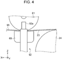
- Fig. 4 is a view illustrating a state that the medium is pressed against a transport belt with the heating and pressing portion.
- Fig. 5 is a view illustrating a state in which the heating and pressing portion is separated from the medium.
- a lifting device 92 shown in Figs. 4 and 5 is omitted for convenience of explanation.
- the medium close contact portion 60 brings the medium 95 into close contact with the transport belt 23.
- the medium close contact portion 60 is provided on the upstream side (-X axial side) of the printing unit 40 in the transport direction.
- the medium close contact portion 60 has the heating and pressing portion 61, the abutting portion 69, and a moving mechanism 62.
- the heating and pressing portion 61 is formed in a cylindrical or columnar shape longer than the width of the medium 95 and is provided so as to be rotatable in the circumferential direction.
- the heating and pressing portion 61 is disposed so that the axial line direction intersects with the transport direction so as to rotate in the direction along the transport direction.
- the heating and pressing portion 61 has a heater 61a inside a metal cylinder (column) covered with a resin or the like, and the surface of the heating and pressing portion 61 is heated by the heater 61a.
- the heater 61a can be constituted by a heating wire made of, for example, an alloy containing nickel and chromium as a main component (nichrome), or an alloy of iron, chromium and aluminum (Kanthal (registered trademark)).
- the heating and pressing portion 61 presses the medium 95 supplied from the transport roller 22 against the transport belt 23 by its own weight. At this time, the transport belt 23 is heated via the medium 95. Since the adhesive 29 increasing in adhesiveness by heating is applied to the surface 23a of the transport belt 23, the medium 95 is suitably adhered to the transport belt 23.
- a plurality of the heaters 61a are provided toward the intersecting direction (Y axial direction) intersecting with the transport direction.
- the heating and pressing portion 61 is divided into five regions, and the heater 61a is built in each of the regions.
- the region (width) for heating the heating and pressing portion 61 by changing the number of divisions of the heater 61a to be used according to the width of the medium, it is possible to change the region (width) for heating the heating and pressing portion 61.
- the number of divisions of the heater 61a is an example, and the number of divisions may be changed according to the type of the width of the medium 95 usable in the printing apparatus 100.
- the moving mechanism 62 allows the heating and pressing portion 61 to move in the transport direction.
- the moving mechanism 62 includes a pressing portion moving motor 63, a first rotating portion 68, a belt 64, a second rotating portion 65, and arm portions 66 and 67.
- the heating and pressing portion 61 is connected to the second rotating portion 65 via the arm portions 66 and 67.
- the second rotating portion 65 is connected to the pressing portion moving motor 63 via the belt 64 and the first rotating portion 68.
- the control unit 1 drives the pressing portion moving motor 63 to rotate the first rotating portion 68 in the rotation direction C, and the rotation force is transmitted to the second rotating portion 65 via the belt 64, and as the second rotating portion 65 rotates in the rotation direction C, the heating and pressing portion 61 is swung in the transport direction (+X axial direction) and a direction opposite to the transport direction (-X axial direction) in a moving range L1 via the arm portions 66 and 67. This makes it possible to suppress heating marks being left on the medium 95.
- the abutting portion 69 is provided so as to indirectly abut on the heating and pressing portion 61 via the transport belt 23.
- the abutting portion 69 has a rectangular shape which is equal to or longer than the length of the heating and pressing portion 61 in the intersecting direction and is formed at a position including the moving range L1 of the heating and pressing portion 61 in the transport direction. In this way, in a case where the heating and pressing portion 61 is swung in the transport direction by the moving mechanism 62, the medium 95, the transport belt 23, and the adhesive 29 can be suitably heated and pressed between the heating and pressing portion 61 and the abutting portion 69.
- the abutting portion 69 is provided with a temperature measuring unit 69a for measuring the temperature of the transport belt 23 inside a metallic casing covered with a cushioning material or the like.
- a temperature measuring unit 69a for example, a thermocouple or the like can be used.
- the control unit 1 can control the heater 61a based on the temperature measured by the temperature measuring unit 69a, thereby keeping the transport belt 23 at a predetermined temperature.
- a plurality of the temperature measuring units 69a may be provided according to the number of divisions of the heater 61a.
- the temperature measuring unit 69a is described as being configured with a thermocouple or the like provided in the abutting portion 69, a non-contact type thermometer using infrared rays may be used.
- the medium close contact portion 60 is provided with the lifting device 92 for separating the heating and pressing portion 61 from the medium 95.
- the lifting device 92 can be constituted by an air cylinder that supports both ends of the heating and pressing portion 61 in the intersecting direction from below (-Z axial side).
- a rod 92a of the lifting device 92 air cylinder
- the whole heating and pressing portion 61 is lifted and separated from the medium 95.
- the rod 92a is lowered, the rod 92a and the heating and pressing portion 61 are separated from each other, and the heating and pressing portion 61 is configured to press the medium 95 by its own weight.
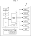
- Fig. 6 is an electrical block diagram illustrating an electrical configuration of the printing apparatus. Next, the electrical configuration of the printing apparatus 100 will be described with reference to Fig. 6 .
- the printing apparatus 100 includes an input device 6 to which printing conditions or the like are input, the control unit 1 which controls each part of the printing apparatus 100, or the like.
- the input device 6 a desktop type or a laptop type personal computer (PC), a tablet type terminal, a portable terminal, and the like can be used.
- the input device 6 may be provided separately from the printing apparatus 100.
- the control unit 1 includes an interface (I/F) 2, a central processing unit (CPU) 3, a storage unit 4, a control circuit 5 and the like.
- the interface 2 is a receiving unit that receives information such as the printing conditions and the type of medium input by the input device 6.
- the interface 2 transmits and receives data between the input device 6 and the control unit 1 for handling input signals and images.
- the CPU 3 is an arithmetic processing device for processing an input signal from various measuring device groups 7 including the temperature measuring unit 69a, and controlling a printing operation of the printing apparatus 100.
- the storage unit 4 is a storage medium for securing an area for storing a program of the CPU 3 or a work area, and has a storage element such as random access memory (RAM), electrically erasable programmable read-only memory (EEPROM), and the like.
- RAM random access memory
- EEPROM electrically erasable programmable read-only memory
- the control unit 1 controls driving of a discharge head provided in the head unit 42 by a control signal output from the control circuit 5 and discharges ink toward the medium 95.
- the control unit 1 controls driving of the motor provided in the carriage moving unit 45 by the control signal output from the control circuit 5 and reciprocally moves the carriage 43 mounted with the head unit 42 in a main scanning direction (Y axial direction).
- the control unit 1 controls driving of the motor provided in the belt driving roller 25 by the control signal output from the control circuit 5 and rotationally moves the transport belt 23. In this way, the medium 95 mounted on the transport belt 23 is moved in the transport direction (+X axial direction).
- the control unit 1 controls the pressing portion moving motor 63 provided in the moving mechanism 62 by the control signal output from the control circuit 5 to swing the heating and pressing portion 61 in the transport direction.
- the control unit 1 controls the voltage applied to the heater 61a based on the control signal output from the control circuit 5 based on the temperature measured by the temperature measuring unit 69a and controls the amount of heat generated by the heater 61a.
- the control unit 1 raises and lowers the lifting device 92 by a control signal output from the control circuit 5 so as to separate the heating and pressing portion 61 from the medium 95 or to press the medium 95 against the transport belt 23 by the heating and pressing portion 61. Further, the control unit 1 controls each device (not illustrated).
- Fig. 7 is a flowchart explaining the printing method of a printing apparatus.
- Fig. 8 is a table illustrating a relationship between a fabric type and fabric thickness and a temperature of the heating and pressing portion. Next, a printing method of the printing apparatus 100 will be described with reference to Figs. 7 and 8 .
- step S1 print information is received.
- the control unit 1 receives input of print data for printing an image on the medium 95, or the print information including the type of the medium 95 and a print mode from the input device 6, and stores it in the storage unit 4.
- step S2 the lifting device 92 is lowered.
- the control unit 1 controls the lifting device 92 to lower the rod 92a of the lifting device 92 (air cylinder). As a result, the medium 95 is pressed against the transport belt 23 by the heating and pressing portion 61.
- step S3 the heater 61a is operated based on the width of the medium 95.
- the print information received in step S1 includes information on a fabric width of the medium 95 or the end portion processing of the fabric.
- the control unit 1 changes the temperature for each of the plurality of heaters 61a according to the fabric width. For example, in a case where the medium 95 having a fabric width narrower than the width of the transport belt 23 is used, the temperature of the heater 61a provided at a position where the medium 95 is not mounted is lowered or the operation is stopped. As a result, the power consumption of the printing apparatus 100 can be reduced. Further, since the adhesive 29 in the portion where the medium 95 is not mounted is not heated and the adhesive force remains low, adhesion of dust in this portion can be reduced.
- the control unit 1 controls the temperature of the heater 61a provided at the abutting position where the heating and pressing portion 61 abuts on the end portion of the medium 95, in accordance with the width of the medium 95 and information on the end portion processing, to be higher than the temperature of the heater 61a provided a position other than the abutting position.
- heat is suitably transferred from the heating and pressing portion 61 to the adhesive 29, so that the medium 95 is more likely to be brought into close contact with the transport belt 23 via the adhesive 29.
- step S4 the temperature of the heating and pressing portion 61 is changed based on the type of the medium 95.
- the print information received in step S1 includes information on the fabric type and the fabric thickness of the medium 95.
- a table showing the relationship between the fabric type and fabric thickness and the temperature of the heating and pressing portion 61 is stored in the storage unit 4 in advance.
- tables similar to the table of fabric type of cotton illustrated in Fig. 8 are stored for each fabric type such as silk, wool, and polyester.
- the control unit 1 changes the temperature of the heating and pressing portion 61 with reference to the table stored in the storage unit 4 based on the type of the medium including received information on the fabric type and the fabric thickness of the medium 95. More specifically, for example, in a case where the medium 95 is "fabric type: cotton” and “fabric thickness: medium”, the control unit 1 sets the temperature of the heating and pressing portion 61 to "medium”, and controls the voltage applied to the heater 61a based on the temperature measured by the temperature measuring unit 69a. Accordingly, even in the case of using the medium 95 having different fabric types and fabric thicknesses, heat is transferred to the adhesive 29 without damaging the appearance of the medium 95, so that the medium 95 can suitably be brought into close contact with the transport belt 23.
- the temperature of the heating and pressing portion 61 is set to "high". This is because in the case where the medium 95 is thick, the energy required for heating is large. Further, in a case where the medium 95 is "fabric type: cotton” and “fabric thickness: thin", the temperature of the heating and pressing portion 61 is set to "low". In the case where the medium 95 is thin, energy required for heating is small.
- step S5 a moving speed of the heating and pressing portion 61 is set.
- the control unit 1 sets the speed at which the heating and pressing portion 61 is moved to a predetermined moving speed and controls the moving mechanism 62 to swing the heating and pressing portion 61 at the predetermined moving speed within the moving range L1.
- steps S2 to S5 have been described in different steps, but steps S2 to S5 are performed substantially at the same time or can be performed in a different order.
- step S6 printing is performed.
- the control unit 1 alternately repeats a main scanning which controls the head unit 42 and the carriage moving unit 45 to move the head unit 42 while discharging ink from the discharge head, and a sub-scanning which controls the belt driving roller 25 to transport the medium 95 in the transport direction.
- a main scanning which controls the head unit 42 and the carriage moving unit 45 to move the head unit 42 while discharging ink from the discharge head
- a sub-scanning which controls the belt driving roller 25 to transport the medium 95 in the transport direction.
- step S7 the heater 61a and the moving mechanism 62 are stopped.
- the control unit 1 stops driving the heater 61a and the moving mechanism 62.
- step S8 the lifting device 92 is raised.
- the control unit 1 controls the lifting device 92 (air cylinder) to raise the rod 92a and separates the heating and pressing portion 61 from the medium 95. This makes it possible to suppress the heating marks being left on the medium 95.
- steps S7 and S8 are described in different steps, but step S7 and step S8 are performed substantially at the same time, or in the reverse order.
- the printing apparatus 100 has the heating and pressing portion 61 for heating the medium 95 and pressing the medium against the transport belt 23 and a control unit 1 for moving the heating and pressing portion 61 along the transport direction. Even when the transport of the medium 95 is stopped, the heating and pressing portion 61 repeats movement (swinging) in the transport direction by the moving mechanism 62 controlled by the control unit 1. As a result, it is possible to suppress the heating marks being left on the medium 95 and damaging the appearance of the medium 95.
- the transport belt 23 of the printing apparatus 100 is coated with the adhesive 29 which increases its adhesiveness by heating. Since the adhesive 29 is heated by the heat from the heating and pressing portion 61 swinging in the transport direction and the medium 95 is pressed against the adhesive 29 on the transport belt 23 by the heating and pressing portion 61, it is possible to suitably adhere the medium 95 to the transport belt 23.
- the printing apparatus 100 is provided with the abutting portion 69 that indirectly abuts on the heating and pressing portion 61 via the transport belt 23 at a position including the moving range L1 of the heating and pressing portion 61.
- the medium 95, the transport belt 23, and the adhesive 29 can be suitably heated and pressed between the heating and pressing portion 61 and the abutting portion 69.
- the printing apparatus 100 includes the temperature measuring unit 69a for measuring the temperature of the transport belt 23. By controlling the heater 61a based on the temperature measured by the temperature measuring unit 69a, the control unit 1 can keep the transport belt 23 at a predetermined temperature.
- the control unit 1 changes the temperature of the heating and pressing portion 61 based on the type of the medium 95 (fabric type, fabric thickness). As a result, heat is transferred to the adhesive 29 without damaging the appearance of the medium 95, so that the medium 95 can be suitably brought into close contact with the transport belt 23.
- the plurality of heaters 61a are provided in the heating and pressing portion 61.
- the control unit 1 changes the number and the temperature of the heaters 61a to be operated according to the width of the medium 95, the power consumption of the printing apparatus 100 can be reduced.
- the control unit 1 controls the temperature of the heater 61a provided at the abutting position where the heating and pressing portion 61 abuts on the end portion of the medium 95 to be higher than the temperature of the heater 61a provided at the position other than the abutting position.
- heat is suitably transferred from the heating and pressing portion 61 to the adhesive 29, so that the medium 95 is more likely to come into close contact with the transport belt 23.
- control unit 1 When stopping the printing operation, the control unit 1 raises the lifting device 92 to separate the heating and pressing portion 61 from the medium 95, so that it is possible to suppress the heating marks being left on the medium 95.
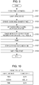
- Fig. 9 is a flowchart explaining a printing method of a printing apparatus according to Modification Example 1.
- Fig. 10 is a table illustrating a relationship between the fabric type and fabric thickness and a moving speed of the heating and pressing portion.
- the printing method of the printing apparatus 100 described in the modification example is different from the embodiment in that the moving speed of a heating medium portion 61 is changed in accordance with the type (fabric type) of the medium 95 and the fabric thickness, instead of the temperature. However, it is possible to control both the moving speed and temperature in this way.
- a printing method of the printing apparatus 100 according to Modification Example 1 will be described with reference to Figs. 9 and 10 . Since the configuration of the printing apparatus 100 is the same as that of the embodiment, its description will be omitted. In the flowchart illustrated in Fig. 9 , since steps S101 to S103 are the same as steps S1 to S3 described in the embodiment, and steps S106 to S108 are the same as steps S6 to S8 described in the embodiment, their explanation is omitted.
- step S104 the temperature of the heating and pressing portion 61 is set.
- the control unit 1 sets the temperature at which the heating and pressing portion 61 is heated as a predetermined temperature and controls the voltage to be applied to the heater 61a based on the temperature measured by the temperature measuring unit 69a. As a result, the heating and pressing portion 61 is heated to a predetermined temperature, and the temperature is maintained.
- step S105 the moving speed of the heating and pressing portion 61 is changed based on the type of the medium 95.
- the print information received in step S101 includes information on the fabric type and fabric thickness of the medium 95.
- a table showing the relationship between the fabric type and the fabric thickness and the moving speed at the time of swinging the heating and pressing portion 61 is stored in the storage unit 4 in advance.
- tables similar to the table of fabric type of cotton illustrated in Fig. 10 are stored for each fabric type such as silk, wool, and polyester.
- the control unit 1 changes the moving speed of the heating and pressing portion 61 with reference to the table stored in the storage unit 4 based on the type of the medium including received information on the fabric type and the fabric thickness of the medium 95. More specifically, for example, in a case where the medium 95 is "fabric type: cotton” and “fabric thickness: medium”, the control unit 1 sets the moving speed of the heating and pressing portion 61 to “medium” and controls the moving mechanism 62 to swing the heating and pressing portion 61 at the moving speed of "medium” within the moving range L1. As a result, heat is transferred to the adhesive 29 without damaging the appearance of the medium 95, so that the medium 95 can be suitably brought into close contact with the transport belt 23.
- the moving speed of the heating and pressing portion 61 is set to "slow". In the case where the medium 95 is thick, since the energy necessary for heating is large, the contact time between the medium 95 and the heating and pressing portion 61 is lengthened. Further, in a case where the medium 95 is "fabric type: cotton” and “fabric thickness: thin”, the moving speed of the heating and pressing portion 61 is set to "slow". In the case where the medium 95 is thin, wrinkles and the like are likely to occur and transportation becomes difficult. Therefore, the transport amount per unit time of the medium 95 tends to decrease (transport speed becomes slow). Therefore, the moving speed of the heating and pressing portion 61 is made slow.
- the moving speed of the heating and pressing portion 61 may be set to "fast".
- Fig. 11 is a flowchart explaining a printing method of a printing apparatus according to Modification Example 2.
- Fig. 12 is a table illustrating a relationship between a fabric type and print mode and the temperature of the heating and pressing portion.
- the printing method of the printing apparatus 100 described in this modification example is different from the embodiment in that the temperature of the heating medium portion 61 is changed in accordance with the type (fabric type) of the medium 95 and the print mode (print speed).
- a printing method of the printing apparatus 100 according to Modification Example 2 will be described with reference to Figs. 11 and 12 . Since the configuration of the printing apparatus 100 is the same as that of the embodiment, its description will be omitted. In the flowchart illustrated in Fig. 11 , since steps S201 to S203 are the same as steps S1 to S3 described in the embodiment, and steps S205 to S208 are the same as steps S5 to S8 described in the embodiment, its explanation is omitted.
- step S204 the temperature of the heating and pressing portion 61 is changed based on the print speed.
- the print mode (print information) received in step S201 information on the print speed of printing performed by the printing unit 40 is included.
- a table showing the relationship between the fabric type and the print mode and the temperature of the heating and pressing portion 61 is stored in the storage unit 4 in advance.
- tables similar to the table of fabric type of cotton illustrated in Fig. 12 are stored for each fabric type such as silk, wool, and polyester.
- the control unit 1 changes the temperature of the heating and pressing portion 61 with reference to the table stored in the storage unit 4 based on the received information on the print speed included in fabric type of the medium 95 and the print mode.
- the print speed corresponds to the transport amount by which the medium 95 is transported in one sub-scanning in the sub-scanning in which the medium 95 is transported in the transport direction. More specifically, the print speed refers to the transport amount per unit time (transport speed). In a case where the print mode is "super-high image quality", the print speed is slower than "high image quality” (transport amount per unit time is small) and in a case where the print mode is "fast”, it means that the print speed is faster than "high image quality" (that is, the transport amount per unit time is larger).
- the control unit 1 sets the temperature of the heating and pressing portion 61 to "medium” and controls the voltage applied to the heater 61a based on the temperature measured by the temperature measuring unit 69a. As a result, heat is transferred to the adhesive 29 without damaging the appearance of the medium 95, so that the medium 95 can be suitably brought into close contact with the transport belt 23. Further, in a case where the medium 95 is "fabric type: cotton” and “print mode: super-high image quality", the temperature of the heating and pressing portion 61 is set to "low".
- Fig. 13 is a flowchart explaining a printing method of a printing apparatus according to Modification Example 3.
- Fig. 14 is a table illustrating a relationship between the fabric type and print mode and the moving speed of the heating and pressing portion.
- the printing method of the printing apparatus 100 described in this modification example is different from the embodiment in that the moving speed of the heating medium portion 61 is changed according to the type (fabric type) of the medium 95 and the print mode (print speed).
- a printing method of the printing apparatus 100 according to Modification Example 3 will be described with reference to Figs. 13 and 14 . Since the configuration of the printing apparatus 100 is the same as that of the embodiment, its description will be omitted. In the flowchart illustrated in Fig. 13 , since steps S301 to S303 are the same as steps S1 to S3 described in the embodiment, and steps S306 to S308 are the same as steps S6 to S8 described in the embodiment, its explanation is omitted.
- step S304 the temperature of the heating and pressing portion 61 is set.
- the control unit 1 sets the temperature at which the heating and pressing portion 61 is heated as a predetermined temperature and controls the voltage to be applied to the heater 61a based on the temperature measured by the temperature measuring unit 69a. As a result, the heating and pressing portion 61 is heated to a predetermined temperature, and the temperature is maintained.
- step S305 the moving speed of the heating and pressing portion 61 is changed based on the print speed.
- the print mode print information
- information on the print speed of printing performed by the printing unit 40 is included.
- the relationship between the print mode and the print speed is the same as that of Modification Example 2.
- a table showing the relationship between the fabric type and the print mode and the moving speed when swinging the heating and pressing portion 61 is stored in the storage unit 4 in advance.
- tables similar to the table of fabric type of cotton illustrated in Fig. 14 are stored for each fabric type such as silk, wool, and polyester.
- the control unit 1 changes the moving speed of the heating and pressing portion 61 with reference to the table stored in the storage unit 4 based on the received information on the print speed included in fabric type of the medium 95 and the print mode. Specifically, in a case where the medium 95 is "fabric type: cotton" and “print mode: high image quality", for example, the control unit 1 sets the moving speed of the heating and pressing portion 61 to "medium”, and controls the moving mechanism 62 to swing the heating and pressing portion 61 at the moving speed of "medium” within the moving range L1. As a result, heat is transferred to the adhesive 29 without damaging the appearance of the medium 95, so that the medium 95 can be suitably brought into close contact with the transport belt 23.
- the moving speed of the heating and pressing portion 61 is set to "slow".
- the print mode is "super-high image quality”
- the moving speed of the heating and pressing portion 61 is set to "high speed”.
- the print mode is "fast” since the print speed is high and the contact time between the medium 95 and the heating and pressing portion 61 is shortened, it is preferable to increase the moving speed of the heating and pressing portion 61 in order to perform sufficient heating.
- Fig. 15 is a flowchart explaining a printing method of a printing apparatus according to Modification Example 4.
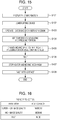
- Fig. 16 is a table illustrating a relationship between the fabric type and print mode and a moving range of the heating and pressing portion.
- the printing method of the printing apparatus 100 described in this modification example is different from the embodiment in that the moving range of the heating medium portion 61 is changed in accordance with the type (fabric type) of the medium 95 and the print mode (print speed).
- the moving range could be changed based on the material thickness instead, or as well, in other examples.
- a printing method of the printing apparatus 100 according to Modification Example 4 will be described with reference to Figs. 15 and 16 . Since the configuration of the printing apparatus 100 is the same as that of the embodiment, its description will be omitted. In the flowchart illustrated in Fig. 15 , since steps S401 to S403 are the same as steps S1 to S3 described in the embodiment, and steps S406 to S408 are the same as steps S6 to S8 described in the embodiment, its explanation is omitted.
- step S404 the temperature of the heating and pressing portion 61 is set.
- the control unit 1 sets the temperature at which the heating and pressing portion 61 is heated as a predetermined temperature and controls the voltage to be applied to the heater 61a based on the temperature measured by the temperature measuring unit 69a. As a result, the heating and pressing portion 61 is heated to a predetermined temperature, and the temperature is maintained.
- step S405 the moving range of the heating and pressing portion 61 is changed based on the print speed.
- the print mode print information
- information on the print speed of printing performed by the printing unit 40 is included.
- the relationship between the print mode and the print speed is the same as that of Modification Example 2.
- a table showing the relationship between the fabric type and the print mode and the moving range when the heating and pressing portion 61 is swung is stored in the storage unit 4 in advance.
- tables similar to the table of fabric type of cotton illustrated in Fig. 16 are stored for each fabric type such as silk, wool, and polyester.
- the control unit 1 changes the moving range of the heating and pressing portion 61 in the transport direction with reference to the table stored in the storage unit 4 based on the received information on the print speed included in fabric type of the medium 95 and print mode. More specifically, for example, in a case where the medium 95 is "fabric type: cotton" and “print mode: high image quality", the control unit 1 sets the moving range of the heating and pressing portion 61 to “medium”, and controls the moving mechanism 62 to swing the heating and pressing portion 61 in the moving range of "medium”. As a result, heat is transferred to the adhesive 29 without damaging the appearance of the medium 95, so that the medium 95 can be suitably brought into close contact with the transport belt 23.
- the moving range of the heating and pressing portion 61 is set to "narrow". In a case where the print mode is "super-high image quality”, it is preferable that the transport amount per unit time be small, and the moving range of the heating and pressing portion 61 be also narrowed accordingly. Further, in a case where the medium 95 is "fabric type: cotton” and “print mode: fast”, the moving range of the heating and pressing portion 61 is set to "wide”. In the case where the print mode is "fast”, it is preferable that the transport amount per unit time be large, and the moving range of the heating and pressing portion 61 be also preferably widened accordingly.
- the printing method of changing one of the temperature, the moving speed, and the moving range of the heating and pressing portion 61 has been described, but it is also possible to change two or more conditions among the temperature, the moving speed, and the moving range of the heating and pressing portion 61 based on at least one information of the fabric type, the fabric thickness, and the print speed (print mode). Therefore, any one or more of the embodiments and modification examples can be combined.
- control unit 1 changes the temperature, the moving speed, and/or the moving range of the heating and pressing unit 61 with reference to the table based on the input print information (fabric type, fabric thickness, print speed, and/or the like), the user may directly input the temperature, the moving speed, and moving range of the heating and pressing portion 61 to the printing apparatus 100.
Landscapes
- Health & Medical Sciences (AREA)
- General Health & Medical Sciences (AREA)
- Toxicology (AREA)
- Ink Jet (AREA)
Abstract
Description
- The present invention relates to a printing apparatus.
- Recently, in textile printing on fabrics such as cotton, silk, wool, chemical fiber, and mixed fabrics, an ink jet type printing apparatus which discharges ink toward a surface of fabrics and performs printing patterns or the like on fabrics is used. The printing apparatus used in textile printing is provided with a transport belt which mounts a medium and transports the medium in a transport direction to handle fabrics having flexibility as a medium. In this kind of printing apparatus, an apparatus having a mechanism for bringing the transport belt and the medium into close contact with each other is known. For example, Chinese Utility Model No.
CN 204322762 U discloses an ink jet type printing machine (printing apparatus) including a pressing roller with a heating function for pressing a medium against a transport belt while heating the medium. - However, in the printing apparatus described in Chinese Utility Model No.
CN 204322762 U , a pressing roller with a heating function is disposed so as to press an upstream side driving roller via the transport belt. In other words, the pressing roller with heating function always presses the medium from one point on the upstream side driving roller. In the ink jet printing apparatus, the medium is intermittently transported in accordance with a printing operation. When the transport of the medium is stopped, the same portion of the medium is heated and pressed, so striped heating marks along a direction intersecting with the transport direction are left on the medium, and the appearance of the medium may be damaged. - The invention can be realized in the following aspects or application examples.
- According to this application example, there is provided a printing apparatus including a printing unit which performs printing on a medium; a transport belt which supports the medium; a driving roller which transports the medium in a transport direction by rotating the transport belt; a heating and pressing portion which has a heater, and is provided to be movable along the transport direction while heating the medium and pressing the medium against the transport belt; and a control unit which controls a movement and a temperature of the heating and pressing portion.
- According to the application example, the printing apparatus is provided with the heating and pressing portion that is movable along the transport direction while heating and pressing the medium. Even when the transport of the medium is stopped, since the heating and pressing portion is moved in the transport direction by the control unit, it is possible to suppress heating marks being left on the medium and damaging the appearance of the medium.
- In the printing apparatus of the application example, it is preferable that the medium be adhered to the transport belt via an adhesive applied to the transport belt, and adhesiveness of the adhesive increase by heating.
- According to the application example, since the adhesive which increases its adhesiveness by heating is applied to the transport belt, the medium can be suitably adhered to the transport belt by heating and pressing by the heating and pressing portion.
- It is preferable that the printing apparatus of the application example include an abutting portion which indirectly abuts on the heating and pressing portion via the transport belt, in which the abutting portion be formed at a position including a moving range of the heating and pressing portion in the transport direction.
- According to the application example, the printing apparatus has an abutting portion that can indirectly abut on the heating and pressing portion via the transport belt. Since the abutting portion is formed at a position including the moving range of the heating and pressing portion, even in a case where the heating and pressing portion is moved along the transport direction, the medium and the transport belt can be suitably heated and pressed between the heating and pressing portion and the abutting portion.
- In the printing apparatus of the application example, it is preferable that the control unit change the temperature of the heating and pressing portion based on a type of the medium.
- According to the application example, since the control unit changes the temperature of the heating and pressing portion based on the type of the medium, it is possible to suitably bring the medium into close contact with the transport belt without damaging the appearance of the medium.
- In the printing apparatus of the application example, it is preferable that the control unit change a moving speed of the heating and pressing portion based on the type of the medium.
- According to the application example, since the control unit changes the moving speed of the heating and pressing portion based on the type of medium, it is possible to suitably bring the medium into close contact with the transport belt without damaging the appearance of the medium.
- In the printing apparatus of the application example, it is preferable that the control unit receive input of a print mode including information on a print speed of printing performed by the printing unit, and change the temperature of the heating and pressing portion based on the print speed of the print mode.
- According to the application example, since the control unit changes the temperature of the heating and pressing portion based on the information on the print speed included in the print mode, that is, the transport speed at which the medium is transported in the transport direction, the medium can be suitably brought into close contact with the transport belt.
- In the printing apparatus of the application example, it is preferable that the control unit receive input of the print mode including information on the print speed of printing performed by the printing unit, and change the moving speed of the heating and pressing portion based on the print speed of the print mode.
- According to the application example, since the control unit changes the moving speed of the heating and pressing portion based on the information on the print speed included in the print mode, that is, the transport speed at which the medium is transported in the transport direction, it is possible to suitably bring the medium into close contact with the transport belt.
- In the printing apparatus of the application example, it is preferable that the control unit receive input of the print mode including information on the print speed of printing performed by the printing unit, and change the moving range of the heating and pressing portion in the transport direction based on the print speed of the print mode.
- According to the application example, since the control unit changes the moving range of the heating and pressing portion based on the information on the print speed included in the print mode, that is, the transport speed at which the medium is transported in the transport direction, it is possible to suitably bring the medium into close contact with the transport belt.
- It is preferable that the printing apparatus of the application example include a temperature measuring unit which measures a temperature of the transport belt.
- According to the application example, since the printing apparatus is provided with the temperature measuring unit for measuring the temperature of the transport belt, the control unit controls the temperature of the heating and pressing portion based on the temperature measured by the temperature measuring unit, so that the transport belt can be kept at a predetermined temperature.
- In the printing apparatus of the application example, it is preferable that a plurality of the heaters of the heating and pressing portion be provided in an intersecting direction intersecting with the transport direction, and the control unit change the temperature for each of the plurality of heaters.
- According to the application example, the plurality of heaters of the heating and pressing portion are provided toward the intersecting direction intersecting with the transport direction, that is, the width direction of the medium. For example, in the case of using mediums having different width sizes, it is possible to reduce the power consumption of the printing apparatus by changing the number of heaters to be heated according to the width of the medium.
- In the printing apparatus of the application example, it is preferable that the control unit control the temperature of the heater provided at an abutting position where the heating and pressing portion abuts on an end portion of the medium in the intersecting direction to be higher than the temperature of the heater provided at a position other than the abutting position.
- According to the application example, the heat transferred from the heating and pressing portion to the transport belt via the medium is easily released from the end portion of the medium. Further, for example, in a case where folding processing is performed on the end portion of the medium, the heat of the heating and pressing portion is hard to be transmitted to the transport belt. In view of this, the control unit increases the temperature of the heater provided at the abutting position where the heating and pressing portion abuts on the end portion of the medium to be higher than the temperature of the heater provided at the position other than the abutting position, and the heat is suitably transferred from the heating and pressing portion to the transport belt.
- In the printing apparatus of the application example, it is preferable that control unit separate the heating and pressing portion from the medium when stopping a printing operation.
- According to the application example, when the control unit stops the printing operation, the control unit separates the heating and pressing portion from the medium, so that it is possible to suppress the heating marks being left on the medium.
- Embodiment of the invention will now be described by way of example only with reference to the accompanying drawings, wherein like numbers reference like elements.
-
Fig. 1 is a schematic view illustrating an entire schematic configuration of a printing apparatus according to an embodiment. -
Fig. 2 is a side view illustrating a configuration of a heating and pressing portion. -
Fig. 3 is a perspective view illustrating the configuration of the heating and pressing portion. -
Fig. 4 is a view illustrating a state in which the medium is pressed against a transport belt with the heating and pressing portion. -
Fig. 5 is a view illustrating a state in which the heating and pressing portion is separated from the medium. -
Fig. 6 is an electrical block diagram illustrating an electrical configuration of the printing apparatus. -
Fig. 7 is a flowchart explaining a printing method of the printing apparatus. -
Fig. 8 is a table illustrating a relationship between a fabric type and fabric thickness and a temperature of the heating and pressing portion. -
Fig. 9 is a flowchart explaining a printing method of a printing apparatus according to Modification Example 1. -
Fig. 10 is a table illustrating a relationship between the fabric type and fabric thickness and a moving speed of the heating and pressing portion. -
Fig. 11 is a flowchart explaining a printing method of a printing apparatus according to Modification Example 2. -
Fig. 12 is a table illustrating a relationship between a fabric type and print mode and the temperature of the heating and pressing portion. -
Fig. 13 is a flowchart explaining a printing method of a printing apparatus according to Modification Example 3. -
Fig. 14 is a table illustrating a relationship between the fabric type and print mode and the moving speed of the heating and pressing portion. -
Fig. 15 is a flowchart explaining a printing method of a printing apparatus according to Modification Example 4. -
Fig. 16 is a table illustrating a relationship between the fabric type and print mode and a moving range of the heating and pressing portion. - Hereinafter, an embodiment of the invention will be described with reference to drawings. Furthermore, in each drawing, scales of each layer and member are made different from the actual scales thereof to a size large enough to be recognized.
- Also, in
Figs. 1 to 5 , for convenience of explanation, three axes, X axis, Y axis, and Z axis, orthogonal to each other are illustrated in the drawings, and the tip end side of the arrow illustrating the axial direction is set to"+ side" and base end side to "- side". A direction parallel to the X axis is referred to as an "X axial direction", a direction parallel to the Y axis is referred to as a "Y axial direction", and a direction parallel to the Z axis is referred to as a "Z axial direction". Embodiment -
Fig. 1 is a schematic view illustrating an entire schematic configuration of a printing apparatus according to an embodiment. First, an entire schematic configuration of aprinting apparatus 100 according to the embodiment will be explained with reference toFig. 1 . Furthermore, in the embodiment, an ink jettype printing apparatus 100 which performs textile printing on a medium 95 with forming an image or the like on the medium 95 will be described as an example. - As illustrated in
Fig. 1 , theprinting apparatus 100 includes amedium transport portion 20, a mediumclose contact portion 60, aprinting unit 40, a dryingunit 27, acleaning unit 50, and the like. The printing apparatus also includes a control unit 1 which controls each of these parts. Each part of theprinting apparatus 100 is attached to aframe portion 90. - The
medium transport portion 20 transports the medium 95 in the transport direction. Themedium transport portion 20 includes amedium supply portion 10,transport rollers transport belt 23, abelt rotating roller 24, abelt driving roller 25 as a driving roller,transport rollers medium collecting portion 30. First, a transport path of the medium 95 from themedium supply portion 10 to themedium collecting portion 30 will be described. In addition, in the embodiment, a direction along gravity is set as a Z axis, a direction to which the medium 95 is transported in theprinting unit 40 as an X axis, and a width direction of the medium 95 that intersects with both Z axis and X axis as a Y axis. Furthermore, the positional relationship along the transport direction of the medium 95 or the moving direction of thetransport belt 23 may be referred to as "upstream side" or "downstream side". - The
medium supply portion 10 supplies the medium 95 for forming an image to theprinting unit 40 side. Fabrics such as cotton, silk, wool, and polyester are used as the medium 95. Themedium supply portion 10 includes asupply shaft portion 11 and a bearingportion 12. Thesupply shaft portion 11 is formed in a cylindrical shape or a columnar shape, and is provided so as to be rotatable in a circumferential direction. On thesupply shaft portion 11, a strip-shapedmedium 95 is wound into a roll shape. Thesupply shaft portion 11 is detachably attached to the bearingportion 12. In this way, the medium 95 in a state wound around thesupply shaft portion 11 in advance can be attached to the bearingportion 12 along with thesupply shaft portion 11. - The bearing
portion 12 rotatably supports both ends of thesupply shaft portion 11 in an axial direction. Themedium supply portion 10 includes a rotational driving unit (not illustrated) which rotationally drives thesupply shaft portion 11. The rotational driving unit rotates thesupply shaft portion 11 in a direction in which the medium 95 is sent out. The operation of the rotational driving unit is controlled by the control unit 1. Thetransport rollers medium supply portion 10 to thetransport belt 23. - The
transport belt 23 is held between at least two rollers which rotate thetransport belt 23, and transports the medium 95 in the transport direction (+X axial direction) as thetransport belt 23 rotationally moves. For details, both end portions of a strip-shaped belt of thetransport belt 23 are connected to form an endless shape, and set on and between two rollers, namely of thebelt rotating roller 24 and thebelt driving roller 25. Thetransport belt 23 is held in a state in which a predetermined tension is applied, so the part between thebelt rotating roller 24 and thebelt driving roller 25 become horizontal. On a surface (supporting surface) 23a of thetransport belt 23, an adhesive 29 to which adheres the medium 95 is applied, and the medium 95 is adhered to thetransport belt 23 via the adhesive 29. Thetransport belt 23 supports (holds) the medium 95 supplied from thetransport roller 22 and adhered to the adhesive 29 at the mediumclose contact portion 60 described later. In this way, fabrics having flexibility or the like can be handled as the medium 95. - It is preferable that the adhesive 29 be increased in adhesiveness by being heated. As such adhesive 29, for example, a hot-melt type adhesive containing thermoplastic elastomer SIS as a main component can be used. By heating the adhesive 29 with a heating and
pressing portion 61 described later, the medium 95 can be suitably adhered to thetransport belt 23. - The
belt rotating roller 24 and thebelt driving roller 25 support an innerperipheral surface 23b of thetransport belt 23. Between thebelt rotating roller 24 and thebelt driving roller 25, an abuttingportion 69 for supporting thetransport belt 23, abelt supporting portion 91, and aplaten 46 are provided. The abuttingportion 69 is disposed in a region opposed to the heating andpressing portion 61 via thetransport belt 23 which will be described later, theplaten 46 is disposed in a region opposed to theprinting unit 40 via thetransport belt 23, and thebelt supporting portion 91 is disposed between the abuttingportion 69 and theplaten 46. Since the abuttingportion 69, thebelt supporting portion 91, and theplaten 46 support thetransport belt 23, it is possible to suppress vibration of thetransport belt 23 and the like as thetransport belt 23 is moved. - The
belt driving roller 25 is a driving unit that transports the medium 95 in the transport direction by rotating thetransport belt 23, and includes a motor (not illustrated) that rotationally drives thebelt driving roller 25. Thebelt driving roller 25 is provided on the downstream side from theprinting unit 40 in the transport direction of the medium 95 and thebelt rotating roller 24 is provided on the upstream side from theprinting unit 40. When thebelt driving roller 25 is rotationally driven, thetransport belt 23 rotates as thebelt driving roller 25 rotates, and thebelt rotating roller 24 rotates by the rotation of thetransport belt 23. By the rotation of thetransport belt 23, the medium 95 supported by thetransport belt 23 is transported in the transport direction (+X axial direction), and an image is formed on the medium 95 at theprinting unit 40 described later. - In the embodiment, medium 95 is supported on a side (+Z axial side) where the surface 23a of the
transport belt 23 is opposite to theprinting unit 40, and the medium 95 is transported from thebelt rotating roller 24 side to thebelt driving roller 25 side along with thetransport belt 23. In addition, on a side (-Z axial side) where the surface 23a of thetransport belt 23 is opposite to thecleaning unit 50, only thetransport belt 23 moves to thebelt rotating roller 24 side from thebelt driving roller 25 side. - The
transport roller 26 separates the medium 95 on which an image is formed from the adhesive 29 of thetransport belt 23. Thetransport rollers transport belt 23 to themedium collecting portion 30. - The
medium collecting portion 30 collects the medium 95 transported by themedium transport portion 20. Themedium collecting portion 30 includes a windingshaft portion 31 and a bearingportion 32. The windingshaft portion 31 is formed in a cylindrical shape or a columnar shape, and is provided so as to be rotatable in a circumferential direction. In the windingshaft portion 31, the strip-shapedmedium 95 is wound in a roll shape. The windingshaft portion 31 is detachably attached to the bearingportion 32. In this way, the medium 95 in a state wound around the windingshaft portion 31 can be removed with the windingshaft portion 31. - The bearing
portion 32 rotatably supports both ends of the windingshaft portion 31 in an axial line direction. Themedium collecting portion 30 includes the rotational driving unit (not illustrated) which rotationally drives the windingshaft portion 31. The rotational driving unit rotates the windingshaft portion 31 in a direction on which the medium 95 is wound. The operation of the rotational driving unit is controlled by the control unit 1. - Next, the
printing unit 40, dryingunit 27, and cleaningunit 50 provided along themedium transport portion 20 will be described. - The
printing unit 40 is disposed above (+Z axial side) the arrangement position of thetransport belt 23, and performs printing on the medium 95 mounted on the surface 23a of thetransport belt 23. Theprinting unit 40 includes ahead unit 42, acarriage 43 on which thehead unit 42 is mounted, acarriage moving unit 45 that moves thecarriage 43 to the width direction (Y axial direction) of the medium 95 which intersects with the transport direction, and the like. In thehead unit 42, a plurality of discharge heads (not illustrated) for discharging ink (for example, yellow, cyan, magenta, black, and the like) supplied from an ink supply portion (not illustrated) to the medium 95 mounted on thetransport belt 23 as liquid are provided. - The
carriage moving unit 45 is provided above (+Z axial side) thetransport belt 23. Thecarriage moving unit 45 includes a pair ofguide rails head unit 42 is supported by theguide rails carriage 43. - The
carriage moving unit 45 is provided with a moving mechanism and a power source (not illustrated). As a moving mechanism, for example, a mechanism combining a ball screw with a ball nut, a linear guide mechanism, or the like can be adopted. Moreover, thecarriage moving unit 45 includes a motor (not illustrated) as the power source for moving thecarriage 43 along theguide rails head unit 42 moves in the Y axial direction along with thecarriage 43. - The drying
unit 27 is provided between thetransport roller 26 and thetransport roller 28. The dryingunit 27 dries ink discharged on the medium 95. In the dryingunit 27, for example, an IR heater is included, and it is possible to dry the ink discharged on the medium 95 in a short period of time by driving the IR heater. In this way, it is possible to wind the strip-shapedmedium 95 on which an image or the like is formed around the windingshaft portion 31. - The
cleaning unit 50 is disposed between thebelt rotating roller 24 and thebelt driving roller 25 in the X axial direction. Thecleaning unit 50 includes a cleaning portion 51, apressing portion 52 and a movingportion 53. The movingportion 53 moves integrally with thecleaning unit 50 along afloor surface 99 and fixes the cleaning unit at a predetermined position. - The
pressing portion 52, for example, is a lifting device configured with anair cylinder 56 and aball bush 57, and causes the cleaning portion 51 provided thereabove to move towards and abut the surface 23a of thetransport belt 23. The cleaning portion 51 is set between thebelt rotating roller 24 and thebelt driving roller 25 in a state in which a predetermined tension is applied, and cleans the surface (supporting surface) 23a of thetransport belt 23 moving from thebelt driving roller 25 toward thebelt rotating roller 24 from below (-Z axial direction). - The cleaning portion 51 includes a
cleaning tank 54, a cleaningroller 58 and ablade 55. Thecleaning tank 54 is a tank for storing a cleaning liquid used for cleaning ink or foreign matters adhered to the surface 23a of thetransport belt 23, and the cleaningroller 58 and theblade 55 are provided inside thecleaning tank 54. As a cleaning liquid, for example, water or a water-soluble solvent (alcohol solution or the like) can be used, and a surfactant or an antifoaming agent may be added as necessary. - When the cleaning
roller 58 rotates, the cleaning liquid is supplied to the surface 23a of thetransport belt 23, and the cleaningroller 58 and thetransport belt 23 slide on each other. In this way, the ink adheres to thetransport belt 23, and fibers of the fabrics serving as the medium 95, or the like are removed by the cleaningroller 58. - The
blade 55, for example, can be made of a flexible material such as silicone rubber. Theblade 55 is provided on the downstream side from the cleaningroller 58 in the transport direction of thetransport belt 23. The remaining cleaning liquid on the surface 23a of thetransport belt 23 is removed as theblade 55 and thetransport belt 23 slide on each other. - Next, the configuration of the medium
close contact portion 60 will be described in detail. -
Fig. 2 is a side view illustrating a configuration of a heating and pressing portion.Fig. 3 is a perspective view illustrating the configuration of the heating and pressing portion.Fig. 4 is a view illustrating a state that the medium is pressed against a transport belt with the heating and pressing portion.Fig. 5 is a view illustrating a state in which the heating and pressing portion is separated from the medium. InFigs. 2 and3 , alifting device 92 shown inFigs. 4 and5 is omitted for convenience of explanation. - The medium
close contact portion 60 brings the medium 95 into close contact with thetransport belt 23. The mediumclose contact portion 60 is provided on the upstream side (-X axial side) of theprinting unit 40 in the transport direction. The mediumclose contact portion 60 has the heating andpressing portion 61, the abuttingportion 69, and a movingmechanism 62. - The heating and
pressing portion 61 is formed in a cylindrical or columnar shape longer than the width of the medium 95 and is provided so as to be rotatable in the circumferential direction. The heating andpressing portion 61 is disposed so that the axial line direction intersects with the transport direction so as to rotate in the direction along the transport direction. The heating andpressing portion 61 has aheater 61a inside a metal cylinder (column) covered with a resin or the like, and the surface of the heating andpressing portion 61 is heated by theheater 61a. Theheater 61a can be constituted by a heating wire made of, for example, an alloy containing nickel and chromium as a main component (nichrome), or an alloy of iron, chromium and aluminum (Kanthal (registered trademark)). The heating andpressing portion 61 presses the medium 95 supplied from thetransport roller 22 against thetransport belt 23 by its own weight. At this time, thetransport belt 23 is heated via the medium 95. Since the adhesive 29 increasing in adhesiveness by heating is applied to the surface 23a of thetransport belt 23, the medium 95 is suitably adhered to thetransport belt 23. - In addition, a plurality of the
heaters 61a are provided toward the intersecting direction (Y axial direction) intersecting with the transport direction. In the embodiment, the heating andpressing portion 61 is divided into five regions, and theheater 61a is built in each of the regions. In the case of using the medium 95 having different widths in the intersecting direction, by changing the number of theheaters 61a to be used according to the width of the medium, it is possible to change the region (width) for heating the heating andpressing portion 61. The number of divisions of theheater 61a is an example, and the number of divisions may be changed according to the type of the width of the medium 95 usable in theprinting apparatus 100. - The moving
mechanism 62 allows the heating andpressing portion 61 to move in the transport direction. As shown inFigs. 2 and3 , the movingmechanism 62 includes a pressingportion moving motor 63, a first rotatingportion 68, abelt 64, a secondrotating portion 65, andarm portions pressing portion 61 is connected to the second rotatingportion 65 via thearm portions rotating portion 65 is connected to the pressingportion moving motor 63 via thebelt 64 and the first rotatingportion 68. In theprinting apparatus 100 according to the embodiment, the control unit 1 drives the pressingportion moving motor 63 to rotate the first rotatingportion 68 in the rotation direction C, and the rotation force is transmitted to the second rotatingportion 65 via thebelt 64, and as the second rotatingportion 65 rotates in the rotation direction C, the heating andpressing portion 61 is swung in the transport direction (+X axial direction) and a direction opposite to the transport direction (-X axial direction) in a moving range L1 via thearm portions - The abutting
portion 69 is provided so as to indirectly abut on the heating andpressing portion 61 via thetransport belt 23. The abuttingportion 69 has a rectangular shape which is equal to or longer than the length of the heating andpressing portion 61 in the intersecting direction and is formed at a position including the moving range L1 of the heating andpressing portion 61 in the transport direction. In this way, in a case where the heating andpressing portion 61 is swung in the transport direction by the movingmechanism 62, the medium 95, thetransport belt 23, and the adhesive 29 can be suitably heated and pressed between the heating andpressing portion 61 and the abuttingportion 69. - The abutting
portion 69 is provided with atemperature measuring unit 69a for measuring the temperature of thetransport belt 23 inside a metallic casing covered with a cushioning material or the like. As thetemperature measuring unit 69a, for example, a thermocouple or the like can be used. As a result, the control unit 1 can control theheater 61a based on the temperature measured by thetemperature measuring unit 69a, thereby keeping thetransport belt 23 at a predetermined temperature. It is to be noted that a plurality of thetemperature measuring units 69a may be provided according to the number of divisions of theheater 61a. Although thetemperature measuring unit 69a is described as being configured with a thermocouple or the like provided in the abuttingportion 69, a non-contact type thermometer using infrared rays may be used. - As shown in
Figs. 4 and5 , the mediumclose contact portion 60 is provided with the liftingdevice 92 for separating the heating andpressing portion 61 from the medium 95. The liftingdevice 92 can be constituted by an air cylinder that supports both ends of the heating andpressing portion 61 in the intersecting direction from below (-Z axial side). By extending arod 92a of the lifting device 92 (air cylinder) to the upper side in the vertical direction (+Z axial side), the whole heating andpressing portion 61 is lifted and separated from the medium 95. When therod 92a is lowered, therod 92a and the heating andpressing portion 61 are separated from each other, and the heating andpressing portion 61 is configured to press the medium 95 by its own weight. -
Fig. 6 is an electrical block diagram illustrating an electrical configuration of the printing apparatus. Next, the electrical configuration of theprinting apparatus 100 will be described with reference toFig. 6 . - The
printing apparatus 100 includes aninput device 6 to which printing conditions or the like are input, the control unit 1 which controls each part of theprinting apparatus 100, or the like. As theinput device 6, a desktop type or a laptop type personal computer (PC), a tablet type terminal, a portable terminal, and the like can be used. Theinput device 6 may be provided separately from theprinting apparatus 100. - The control unit 1 includes an interface (I/F) 2, a central processing unit (CPU) 3, a
storage unit 4, acontrol circuit 5 and the like. Theinterface 2 is a receiving unit that receives information such as the printing conditions and the type of medium input by theinput device 6. Theinterface 2 transmits and receives data between theinput device 6 and the control unit 1 for handling input signals and images. TheCPU 3 is an arithmetic processing device for processing an input signal from various measuringdevice groups 7 including thetemperature measuring unit 69a, and controlling a printing operation of theprinting apparatus 100. Thestorage unit 4 is a storage medium for securing an area for storing a program of theCPU 3 or a work area, and has a storage element such as random access memory (RAM), electrically erasable programmable read-only memory (EEPROM), and the like. - The control unit 1 controls driving of a discharge head provided in the
head unit 42 by a control signal output from thecontrol circuit 5 and discharges ink toward the medium 95. The control unit 1 controls driving of the motor provided in thecarriage moving unit 45 by the control signal output from thecontrol circuit 5 and reciprocally moves thecarriage 43 mounted with thehead unit 42 in a main scanning direction (Y axial direction). The control unit 1 controls driving of the motor provided in thebelt driving roller 25 by the control signal output from thecontrol circuit 5 and rotationally moves thetransport belt 23. In this way, the medium 95 mounted on thetransport belt 23 is moved in the transport direction (+X axial direction). - The control unit 1 controls the pressing
portion moving motor 63 provided in the movingmechanism 62 by the control signal output from thecontrol circuit 5 to swing the heating andpressing portion 61 in the transport direction. The control unit 1 controls the voltage applied to theheater 61a based on the control signal output from thecontrol circuit 5 based on the temperature measured by thetemperature measuring unit 69a and controls the amount of heat generated by theheater 61a. The control unit 1 raises and lowers thelifting device 92 by a control signal output from thecontrol circuit 5 so as to separate the heating andpressing portion 61 from the medium 95 or to press the medium 95 against thetransport belt 23 by the heating andpressing portion 61. Further, the control unit 1 controls each device (not illustrated). -
Fig. 7 is a flowchart explaining the printing method of a printing apparatus.Fig. 8 is a table illustrating a relationship between a fabric type and fabric thickness and a temperature of the heating and pressing portion. Next, a printing method of theprinting apparatus 100 will be described with reference toFigs. 7 and 8 . - In step S1, print information is received. The control unit 1 receives input of print data for printing an image on the medium 95, or the print information including the type of the medium 95 and a print mode from the
input device 6, and stores it in thestorage unit 4. - In step S2, the lifting
device 92 is lowered. The control unit 1 controls thelifting device 92 to lower therod 92a of the lifting device 92 (air cylinder). As a result, the medium 95 is pressed against thetransport belt 23 by the heating andpressing portion 61. - In step S3, the
heater 61a is operated based on the width of the medium 95. The print information received in step S1 includes information on a fabric width of the medium 95 or the end portion processing of the fabric. The control unit 1 changes the temperature for each of the plurality ofheaters 61a according to the fabric width. For example, in a case where the medium 95 having a fabric width narrower than the width of thetransport belt 23 is used, the temperature of theheater 61a provided at a position where the medium 95 is not mounted is lowered or the operation is stopped. As a result, the power consumption of theprinting apparatus 100 can be reduced. Further, since the adhesive 29 in the portion where the medium 95 is not mounted is not heated and the adhesive force remains low, adhesion of dust in this portion can be reduced. - In addition, since heat of the end portion in the intersecting direction of the medium 95 is easily released, heat from the heating and
pressing portion 61 is hardly transmitted to the adhesive 29 of thetransport belt 23 via the medium 95. In a case where the end portion of the medium 95 is folded back, heat is further hardly transmitted to the adhesive 29. Therefore, the control unit 1 controls the temperature of theheater 61a provided at the abutting position where the heating andpressing portion 61 abuts on the end portion of the medium 95, in accordance with the width of the medium 95 and information on the end portion processing, to be higher than the temperature of theheater 61a provided a position other than the abutting position. As a result, heat is suitably transferred from the heating andpressing portion 61 to the adhesive 29, so that the medium 95 is more likely to be brought into close contact with thetransport belt 23 via the adhesive 29. - In step S4, the temperature of the heating and
pressing portion 61 is changed based on the type of the medium 95. The print information received in step S1 includes information on the fabric type and the fabric thickness of the medium 95. Further, in thestorage unit 4, a table showing the relationship between the fabric type and fabric thickness and the temperature of the heating andpressing portion 61 is stored in thestorage unit 4 in advance. In thestorage unit 4, tables similar to the table of fabric type of cotton illustrated inFig. 8 are stored for each fabric type such as silk, wool, and polyester. - The control unit 1 changes the temperature of the heating and
pressing portion 61 with reference to the table stored in thestorage unit 4 based on the type of the medium including received information on the fabric type and the fabric thickness of the medium 95. More specifically, for example, in a case where the medium 95 is "fabric type: cotton" and "fabric thickness: medium", the control unit 1 sets the temperature of the heating andpressing portion 61 to "medium", and controls the voltage applied to theheater 61a based on the temperature measured by thetemperature measuring unit 69a. Accordingly, even in the case of using the medium 95 having different fabric types and fabric thicknesses, heat is transferred to the adhesive 29 without damaging the appearance of the medium 95, so that the medium 95 can suitably be brought into close contact with thetransport belt 23. Further, in a case where the medium 95 is "fabric type: cotton" and "fabric thickness: thick", the temperature of the heating andpressing portion 61 is set to "high". This is because in the case where the medium 95 is thick, the energy required for heating is large. Further, in a case where the medium 95 is "fabric type: cotton" and "fabric thickness: thin", the temperature of the heating andpressing portion 61 is set to "low". In the case where the medium 95 is thin, energy required for heating is small. - In step S5, a moving speed of the heating and
pressing portion 61 is set. The control unit 1 sets the speed at which the heating andpressing portion 61 is moved to a predetermined moving speed and controls the movingmechanism 62 to swing the heating andpressing portion 61 at the predetermined moving speed within the moving range L1. For convenience of explanation, steps S2 to S5 have been described in different steps, but steps S2 to S5 are performed substantially at the same time or can be performed in a different order. - In step S6, printing is performed. Based on the print data received in step S1, the control unit 1 alternately repeats a main scanning which controls the
head unit 42 and thecarriage moving unit 45 to move thehead unit 42 while discharging ink from the discharge head, and a sub-scanning which controls thebelt driving roller 25 to transport the medium 95 in the transport direction. By this printing operation, an image or the like is printed on the medium 95. During the printing operation, the medium 95 is intermittently transported, and the transport thereof is stopped during the main scanning. Even in a case where the transport of the medium 95 is stopped, since the heating andpressing portion 61 repeats the movement (shaking) in the transport direction, it is possible to suppress the heating marks being left on the medium 95. - In step S7, the
heater 61a and the movingmechanism 62 are stopped. When the printing in step S6 is ended, the control unit 1 stops driving theheater 61a and the movingmechanism 62. - In step S8, the lifting
device 92 is raised. When stopping the printing operation, the control unit 1 controls the lifting device 92 (air cylinder) to raise therod 92a and separates the heating andpressing portion 61 from the medium 95. This makes it possible to suppress the heating marks being left on the medium 95. For convenience of explanation, steps S7 and S8 are described in different steps, but step S7 and step S8 are performed substantially at the same time, or in the reverse order. - As described above, according to the
printing apparatus 100 according to the embodiment, the following effects can be obtained. - The
printing apparatus 100 has the heating andpressing portion 61 for heating the medium 95 and pressing the medium against thetransport belt 23 and a control unit 1 for moving the heating andpressing portion 61 along the transport direction. Even when the transport of the medium 95 is stopped, the heating andpressing portion 61 repeats movement (swinging) in the transport direction by the movingmechanism 62 controlled by the control unit 1. As a result, it is possible to suppress the heating marks being left on the medium 95 and damaging the appearance of the medium 95. - The
transport belt 23 of theprinting apparatus 100 is coated with the adhesive 29 which increases its adhesiveness by heating. Since the adhesive 29 is heated by the heat from the heating andpressing portion 61 swinging in the transport direction and the medium 95 is pressed against the adhesive 29 on thetransport belt 23 by the heating andpressing portion 61, it is possible to suitably adhere the medium 95 to thetransport belt 23. - The
printing apparatus 100 is provided with the abuttingportion 69 that indirectly abuts on the heating andpressing portion 61 via thetransport belt 23 at a position including the moving range L1 of the heating andpressing portion 61. As a result, even in a case where the heating andpressing portion 61 is moved (swung) in the transport direction, the medium 95, thetransport belt 23, and the adhesive 29 can be suitably heated and pressed between the heating andpressing portion 61 and the abuttingportion 69. - The
printing apparatus 100 includes thetemperature measuring unit 69a for measuring the temperature of thetransport belt 23. By controlling theheater 61a based on the temperature measured by thetemperature measuring unit 69a, the control unit 1 can keep thetransport belt 23 at a predetermined temperature. - The control unit 1 changes the temperature of the heating and
pressing portion 61 based on the type of the medium 95 (fabric type, fabric thickness). As a result, heat is transferred to the adhesive 29 without damaging the appearance of the medium 95, so that the medium 95 can be suitably brought into close contact with thetransport belt 23. - The plurality of
heaters 61a are provided in the heating andpressing portion 61. For example, since the control unit 1 changes the number and the temperature of theheaters 61a to be operated according to the width of the medium 95, the power consumption of theprinting apparatus 100 can be reduced. - In accordance with the width of the medium 95 and the information on the end portion processing, the control unit 1 controls the temperature of the
heater 61a provided at the abutting position where the heating andpressing portion 61 abuts on the end portion of the medium 95 to be higher than the temperature of theheater 61a provided at the position other than the abutting position. As a result, heat is suitably transferred from the heating andpressing portion 61 to the adhesive 29, so that the medium 95 is more likely to come into close contact with thetransport belt 23. - When stopping the printing operation, the control unit 1 raises the
lifting device 92 to separate the heating andpressing portion 61 from the medium 95, so that it is possible to suppress the heating marks being left on the medium 95. - The invention is not limited to the above-described embodiments, and various modifications and improvements can be added to the above-described embodiments. Modification examples will be described below.
-
Fig. 9 is a flowchart explaining a printing method of a printing apparatus according to Modification Example 1.Fig. 10 is a table illustrating a relationship between the fabric type and fabric thickness and a moving speed of the heating and pressing portion. The printing method of theprinting apparatus 100 described in the modification example is different from the embodiment in that the moving speed of aheating medium portion 61 is changed in accordance with the type (fabric type) of the medium 95 and the fabric thickness, instead of the temperature. However, it is possible to control both the moving speed and temperature in this way. - Hereinafter, a printing method of the
printing apparatus 100 according to Modification Example 1 will be described with reference toFigs. 9 and 10 . Since the configuration of theprinting apparatus 100 is the same as that of the embodiment, its description will be omitted. In the flowchart illustrated inFig. 9 , since steps S101 to S103 are the same as steps S1 to S3 described in the embodiment, and steps S106 to S108 are the same as steps S6 to S8 described in the embodiment, their explanation is omitted. - In step S104, the temperature of the heating and
pressing portion 61 is set. The control unit 1 sets the temperature at which the heating andpressing portion 61 is heated as a predetermined temperature and controls the voltage to be applied to theheater 61a based on the temperature measured by thetemperature measuring unit 69a. As a result, the heating andpressing portion 61 is heated to a predetermined temperature, and the temperature is maintained. - In step S105, the moving speed of the heating and
pressing portion 61 is changed based on the type of the medium 95. The print information received in step S101 includes information on the fabric type and fabric thickness of the medium 95. In thestorage unit 4, a table showing the relationship between the fabric type and the fabric thickness and the moving speed at the time of swinging the heating andpressing portion 61 is stored in thestorage unit 4 in advance. In thestorage unit 4, tables similar to the table of fabric type of cotton illustrated inFig. 10 are stored for each fabric type such as silk, wool, and polyester. - The control unit 1 changes the moving speed of the heating and
pressing portion 61 with reference to the table stored in thestorage unit 4 based on the type of the medium including received information on the fabric type and the fabric thickness of the medium 95. More specifically, for example, in a case where the medium 95 is "fabric type: cotton" and "fabric thickness: medium", the control unit 1 sets the moving speed of the heating andpressing portion 61 to "medium" and controls the movingmechanism 62 to swing the heating andpressing portion 61 at the moving speed of "medium" within the moving range L1. As a result, heat is transferred to the adhesive 29 without damaging the appearance of the medium 95, so that the medium 95 can be suitably brought into close contact with thetransport belt 23. Further, in a case where the medium 95 is "fabric type: cotton" and "fabric thickness: thick", the moving speed of the heating andpressing portion 61 is set to "slow". In the case where the medium 95 is thick, since the energy necessary for heating is large, the contact time between the medium 95 and the heating andpressing portion 61 is lengthened. Further, in a case where the medium 95 is "fabric type: cotton" and "fabric thickness: thin", the moving speed of the heating andpressing portion 61 is set to "slow". In the case where the medium 95 is thin, wrinkles and the like are likely to occur and transportation becomes difficult. Therefore, the transport amount per unit time of the medium 95 tends to decrease (transport speed becomes slow). Therefore, the moving speed of the heating andpressing portion 61 is made slow. However, as long as the medium 95 can be easily transported and can be transported in a large amount per unit time (transport speed can be increased) even if the medium 95 is thin, in the case of "fabric thickness: thin", the moving speed of the heating andpressing portion 61 may be set to "fast". -
Fig. 11 is a flowchart explaining a printing method of a printing apparatus according to Modification Example 2.Fig. 12 is a table illustrating a relationship between a fabric type and print mode and the temperature of the heating and pressing portion. The printing method of theprinting apparatus 100 described in this modification example is different from the embodiment in that the temperature of theheating medium portion 61 is changed in accordance with the type (fabric type) of the medium 95 and the print mode (print speed). - Hereinafter, a printing method of the
printing apparatus 100 according to Modification Example 2 will be described with reference toFigs. 11 and 12 . Since the configuration of theprinting apparatus 100 is the same as that of the embodiment, its description will be omitted. In the flowchart illustrated inFig. 11 , since steps S201 to S203 are the same as steps S1 to S3 described in the embodiment, and steps S205 to S208 are the same as steps S5 to S8 described in the embodiment, its explanation is omitted. - In step S204, the temperature of the heating and
pressing portion 61 is changed based on the print speed. In the print mode (print information) received in step S201, information on the print speed of printing performed by theprinting unit 40 is included. Further, in thestorage unit 4, a table showing the relationship between the fabric type and the print mode and the temperature of the heating andpressing portion 61 is stored in thestorage unit 4 in advance. In thestorage unit 4, tables similar to the table of fabric type of cotton illustrated inFig. 12 are stored for each fabric type such as silk, wool, and polyester. - The control unit 1 changes the temperature of the heating and
pressing portion 61 with reference to the table stored in thestorage unit 4 based on the received information on the print speed included in fabric type of the medium 95 and the print mode. The print speed corresponds to the transport amount by which the medium 95 is transported in one sub-scanning in the sub-scanning in which the medium 95 is transported in the transport direction. More specifically, the print speed refers to the transport amount per unit time (transport speed). In a case where the print mode is "super-high image quality", the print speed is slower than "high image quality" (transport amount per unit time is small) and in a case where the print mode is "fast", it means that the print speed is faster than "high image quality" (that is, the transport amount per unit time is larger). - Specifically, in a case where the medium 95 is "fabric type: cotton" and "print mode: high image quality", for example, the control unit 1 sets the temperature of the heating and
pressing portion 61 to "medium" and controls the voltage applied to theheater 61a based on the temperature measured by thetemperature measuring unit 69a. As a result, heat is transferred to the adhesive 29 without damaging the appearance of the medium 95, so that the medium 95 can be suitably brought into close contact with thetransport belt 23. Further, in a case where the medium 95 is "fabric type: cotton" and "print mode: super-high image quality", the temperature of the heating andpressing portion 61 is set to "low". In the case where the print mode is "super-high image quality", since the print speed is slow and the contact time between the medium 95 and the heating andpressing portion 61 is lengthened, sufficient heating can be performed even if the temperature of the heating andpressing portion 61 is low. Further, in a case where the medium 95 is "fabric type: cotton" and "print mode: fast", the temperature of the heating andpressing portion 61 is set to "high". In the case where the print mode is "fast", since the print speed is high and the contact time between the medium 95 and the heating andpressing portion 61 is shortened, in order to perform sufficient heating, it is preferable to increase the temperature of the heating andpressing portion 61 sufficiently. Modification Example 3 -
Fig. 13 is a flowchart explaining a printing method of a printing apparatus according to Modification Example 3.Fig. 14 is a table illustrating a relationship between the fabric type and print mode and the moving speed of the heating and pressing portion. The printing method of theprinting apparatus 100 described in this modification example is different from the embodiment in that the moving speed of theheating medium portion 61 is changed according to the type (fabric type) of the medium 95 and the print mode (print speed). - Hereinafter, a printing method of the
printing apparatus 100 according to Modification Example 3 will be described with reference toFigs. 13 and 14 . Since the configuration of theprinting apparatus 100 is the same as that of the embodiment, its description will be omitted. In the flowchart illustrated inFig. 13 , since steps S301 to S303 are the same as steps S1 to S3 described in the embodiment, and steps S306 to S308 are the same as steps S6 to S8 described in the embodiment, its explanation is omitted. - In step S304, the temperature of the heating and
pressing portion 61 is set. The control unit 1 sets the temperature at which the heating andpressing portion 61 is heated as a predetermined temperature and controls the voltage to be applied to theheater 61a based on the temperature measured by thetemperature measuring unit 69a. As a result, the heating andpressing portion 61 is heated to a predetermined temperature, and the temperature is maintained. - In step S305, the moving speed of the heating and
pressing portion 61 is changed based on the print speed. In the print mode (print information) received in step S301, information on the print speed of printing performed by theprinting unit 40 is included. Here, the relationship between the print mode and the print speed is the same as that of Modification Example 2. In thestorage unit 4, a table showing the relationship between the fabric type and the print mode and the moving speed when swinging the heating andpressing portion 61 is stored in thestorage unit 4 in advance. In thestorage unit 4, tables similar to the table of fabric type of cotton illustrated inFig. 14 are stored for each fabric type such as silk, wool, and polyester. - The control unit 1 changes the moving speed of the heating and
pressing portion 61 with reference to the table stored in thestorage unit 4 based on the received information on the print speed included in fabric type of the medium 95 and the print mode. Specifically, in a case where the medium 95 is "fabric type: cotton" and "print mode: high image quality", for example, the control unit 1 sets the moving speed of the heating andpressing portion 61 to "medium", and controls the movingmechanism 62 to swing the heating andpressing portion 61 at the moving speed of "medium" within the moving range L1. As a result, heat is transferred to the adhesive 29 without damaging the appearance of the medium 95, so that the medium 95 can be suitably brought into close contact with thetransport belt 23. Further, in a case where the medium 95 is "fabric type: cotton" and "print mode: super-high image quality", the moving speed of the heating andpressing portion 61 is set to "slow". In the case where the print mode is "super-high image quality", since the print speed is slow and the contact time between the medium 95 and the heating andpressing portion 61 is lengthened, even if the moving speed of the heating andpressing portion 61 is slow, sufficient heating can be performed. In a case where the medium 95 is "fabric type: cotton" and "print mode: fast", the moving speed of the heating andpressing portion 61 is set to "high speed". In the case where the print mode is "fast", since the print speed is high and the contact time between the medium 95 and the heating andpressing portion 61 is shortened, it is preferable to increase the moving speed of the heating andpressing portion 61 in order to perform sufficient heating. -
Fig. 15 is a flowchart explaining a printing method of a printing apparatus according to Modification Example 4.Fig. 16 is a table illustrating a relationship between the fabric type and print mode and a moving range of the heating and pressing portion. The printing method of theprinting apparatus 100 described in this modification example is different from the embodiment in that the moving range of theheating medium portion 61 is changed in accordance with the type (fabric type) of the medium 95 and the print mode (print speed). The moving range could be changed based on the material thickness instead, or as well, in other examples. - Hereinafter, a printing method of the
printing apparatus 100 according to Modification Example 4 will be described with reference toFigs. 15 and 16 . Since the configuration of theprinting apparatus 100 is the same as that of the embodiment, its description will be omitted. In the flowchart illustrated inFig. 15 , since steps S401 to S403 are the same as steps S1 to S3 described in the embodiment, and steps S406 to S408 are the same as steps S6 to S8 described in the embodiment, its explanation is omitted. - In step S404, the temperature of the heating and
pressing portion 61 is set. The control unit 1 sets the temperature at which the heating andpressing portion 61 is heated as a predetermined temperature and controls the voltage to be applied to theheater 61a based on the temperature measured by thetemperature measuring unit 69a. As a result, the heating andpressing portion 61 is heated to a predetermined temperature, and the temperature is maintained. - In step S405, the moving range of the heating and
pressing portion 61 is changed based on the print speed. In the print mode (print information) received in step S401, information on the print speed of printing performed by theprinting unit 40 is included. Here, the relationship between the print mode and the print speed is the same as that of Modification Example 2. In thestorage unit 4, a table showing the relationship between the fabric type and the print mode and the moving range when the heating andpressing portion 61 is swung is stored in thestorage unit 4 in advance. In thestorage unit 4, tables similar to the table of fabric type of cotton illustrated inFig. 16 are stored for each fabric type such as silk, wool, and polyester. - The control unit 1 changes the moving range of the heating and
pressing portion 61 in the transport direction with reference to the table stored in thestorage unit 4 based on the received information on the print speed included in fabric type of the medium 95 and print mode. More specifically, for example, in a case where the medium 95 is "fabric type: cotton" and "print mode: high image quality", the control unit 1 sets the moving range of the heating andpressing portion 61 to "medium", and controls the movingmechanism 62 to swing the heating andpressing portion 61 in the moving range of "medium". As a result, heat is transferred to the adhesive 29 without damaging the appearance of the medium 95, so that the medium 95 can be suitably brought into close contact with thetransport belt 23. Further, when the medium 95 is "fabric type: cotton" and "print mode: super-high image quality", the moving range of the heating andpressing portion 61 is set to "narrow". In a case where the print mode is "super-high image quality", it is preferable that the transport amount per unit time be small, and the moving range of the heating andpressing portion 61 be also narrowed accordingly. Further, in a case where the medium 95 is "fabric type: cotton" and "print mode: fast", the moving range of the heating andpressing portion 61 is set to "wide". In the case where the print mode is "fast", it is preferable that the transport amount per unit time be large, and the moving range of the heating andpressing portion 61 be also preferably widened accordingly. - In the embodiment and Modification Examples 1 to 4 of the invention, the printing method of changing one of the temperature, the moving speed, and the moving range of the heating and
pressing portion 61 has been described, but it is also possible to change two or more conditions among the temperature, the moving speed, and the moving range of the heating andpressing portion 61 based on at least one information of the fabric type, the fabric thickness, and the print speed (print mode). Therefore, any one or more of the embodiments and modification examples can be combined. - Further, although it is described that the control unit 1 changes the temperature, the moving speed, and/or the moving range of the heating and
pressing unit 61 with reference to the table based on the input print information (fabric type, fabric thickness, print speed, and/or the like), the user may directly input the temperature, the moving speed, and moving range of the heating andpressing portion 61 to theprinting apparatus 100.
Claims (12)
- A printing apparatus (100) comprising:a printing unit (40) configured to perform printing on a medium (95);a transport belt (23) configured to support the medium;a driving roller (25) configured to transport the medium in a transport direction by rotating the transport belt;a heating and pressing portion (61) which has a heater (61a), and is provided to be movable along the transport direction while heating the medium and pressing the medium against the transport belt; anda control unit (1) configured to control a movement and a temperature of the heating and pressing portion.
- The printing apparatus according to Claim 1,
wherein an adhesive is applied to the transport belt so the medium can be adhered to the transport belt, and
wherein adhesiveness of the adhesive is increased by heating. - The printing apparatus according to Claim 1 or Claim 2, further comprising:an abutting portion (69) configured to indirectly abut on the heating and pressing portion via the transport belt,wherein the abutting portion is formed at a position including a moving range (L1) of the heating and pressing portion in the transport direction.
- The printing apparatus according to any one of the preceding claims,
wherein the control unit is configured to change the temperature of the heating and pressing portion based on a type of the medium. - The printing apparatus according to any one of the preceding claims,
wherein the control unit is configured to change a moving speed of the heating and pressing portion based on a type of the medium. - The printing apparatus according to any one of the preceding claims,
wherein the control unit is configured toreceive input of a print mode including information on a print speed of printing performed by the printing unit, andchange the temperature of the heating and pressing portion based on the print speed of the print mode. - The printing apparatus according to any one of the preceding claims,
wherein the control unit is configured toreceive input of the print mode including information on the print speed of printing performed by the printing unit, andchange the moving speed of the heating and pressing portion based on the print speed of the print mode. - The printing apparatus according to any one of the preceding claims,
wherein the control unit is configured toreceive input of a print mode including information on the print speed of printing performed by the printing unit, andchange the moving range of the heating and pressing portion in the transport direction based on the print speed of the print mode. - The printing apparatus according to any one of the preceding claims, further comprising:
a temperature measuring unit (69a) which measures a temperature of the transport belt. - The printing apparatus according to any one of the preceding claims,
wherein a plurality of the heaters (61a) of the heating and pressing portion are provided in an intersecting direction intersecting with the transport direction, and
wherein the control unit is configured to change the temperature for each of the plurality of heaters. - The printing apparatus according to Claim 10,
wherein the control unit is configured to control the temperature of the heater provided at an abutting position where the heating and pressing portion abuts on an end portion of the medium in the intersecting direction to be higher than the temperature of the heater provided at a position other than the abutting position. - The printing apparatus according to any one of the preceding claims,
wherein the control unit is configured to separate the heating and pressing portion from the medium when stopping a printing operation.
Applications Claiming Priority (1)
| Application Number | Priority Date | Filing Date | Title |
|---|---|---|---|
| JP2017099542A JP6988164B2 (en) | 2017-05-19 | 2017-05-19 | Printing equipment |
Publications (2)
| Publication Number | Publication Date |
|---|---|
| EP3403833A1 true EP3403833A1 (en) | 2018-11-21 |
| EP3403833B1 EP3403833B1 (en) | 2020-11-18 |
Family
ID=62217813
Family Applications (1)
| Application Number | Title | Priority Date | Filing Date |
|---|---|---|---|
| EP18173200.9A Active EP3403833B1 (en) | 2017-05-19 | 2018-05-18 | Printing apparatus |
Country Status (3)
| Country | Link |
|---|---|
| EP (1) | EP3403833B1 (en) |
| JP (1) | JP6988164B2 (en) |
| CN (1) | CN108944084B (en) |
Cited By (5)
| Publication number | Priority date | Publication date | Assignee | Title |
|---|---|---|---|---|
| CN112339416A (en) * | 2020-10-27 | 2021-02-09 | 绍兴慧行智能科技有限公司 | Automatic pad printing equipment for textile printing and dyeing and working method thereof |
| EP3858628A1 (en) * | 2020-01-29 | 2021-08-04 | Seiko Epson Corporation | Recording device |
| US11529809B2 (en) | 2020-03-10 | 2022-12-20 | Seiko Epson Corporation | Ink jet printing recording apparatus and ink jet recording method |
| CN116811451A (en) * | 2022-03-28 | 2023-09-29 | 精工爱普生株式会社 | Liquid ejecting apparatus |
| US12351978B2 (en) | 2021-01-29 | 2025-07-08 | Seiko Epson Corporation | Ink jet textile printing method and recording apparatus |
Families Citing this family (11)
| Publication number | Priority date | Publication date | Assignee | Title |
|---|---|---|---|---|
| JP7310294B2 (en) * | 2019-05-22 | 2023-07-19 | セイコーエプソン株式会社 | printer |
| JP7322632B2 (en) * | 2019-09-25 | 2023-08-08 | セイコーエプソン株式会社 | recording device |
| CN111002712A (en) * | 2019-12-30 | 2020-04-14 | 工正集团有限公司 | Ink-jet printer capable of adjusting width |
| JP7359004B2 (en) * | 2020-01-29 | 2023-10-11 | セイコーエプソン株式会社 | Conveyance device and recording device |
| JP7459544B2 (en) * | 2020-02-12 | 2024-04-02 | コニカミノルタ株式会社 | Belt drive device, image forming apparatus |
| US11420380B2 (en) * | 2020-03-24 | 2022-08-23 | Casio Computer Co., Ltd. | Shaping device and production method for shaped object |
| JP7571487B2 (en) | 2020-11-13 | 2024-10-23 | セイコーエプソン株式会社 | Printing device |
| JP7613210B2 (en) * | 2021-03-31 | 2025-01-15 | セイコーエプソン株式会社 | TRANSPORT SYSTEM, TRANSPORT DEVICE, RECORDING SYSTEM, AND METHOD FOR CONTROLLING TRANSPORT DEVICE |
| JP7647260B2 (en) | 2021-04-08 | 2025-03-18 | コニカミノルタ株式会社 | Heating control device and printing device |
| JP7771766B2 (en) * | 2022-01-14 | 2025-11-18 | セイコーエプソン株式会社 | Conveying device and liquid ejecting device |
| JP2024077111A (en) * | 2022-11-28 | 2024-06-07 | セイコーエプソン株式会社 | Conveying device and recording device |
Citations (3)
| Publication number | Priority date | Publication date | Assignee | Title |
|---|---|---|---|---|
| EP2754560A1 (en) * | 2013-01-10 | 2014-07-16 | Seiko Epson Corporation | Recording apparatus |
| CN204322762U (en) | 2014-11-28 | 2015-05-13 | 杭州宏华数码科技股份有限公司 | The cloth pressing roller of the conduction band type inkjet printing machine with heater |
| US20160288533A1 (en) * | 2014-02-25 | 2016-10-06 | Seiko Epson Corporation | Liquid discharge apparatus and medium flattening method |
Family Cites Families (19)
| Publication number | Priority date | Publication date | Assignee | Title |
|---|---|---|---|---|
| JPH09146417A (en) * | 1995-11-17 | 1997-06-06 | Ricoh Co Ltd | Image forming device |
| JPH10123865A (en) * | 1996-10-23 | 1998-05-15 | Ricoh Co Ltd | Image forming device |
| JPH11268412A (en) * | 1998-01-16 | 1999-10-05 | Asahi Optical Co Ltd | Transfer device for pressure sensitive thermal recording |
| JP2000296607A (en) * | 1999-04-16 | 2000-10-24 | Mutoh Ind Ltd | Inkjet printer |
| US6820975B2 (en) * | 2000-09-01 | 2004-11-23 | Konica Corporation | Inkjet recording apparatus and inkjet recording method |
| JP2002067283A (en) * | 2000-09-01 | 2002-03-05 | Konica Corp | Ink jet recorder |
| JP2003054071A (en) * | 2001-08-16 | 2003-02-26 | Konica Corp | Inkjet recorder |
| JP2004306425A (en) * | 2003-04-07 | 2004-11-04 | Konica Minolta Medical & Graphic Inc | Image recording method and image recorder |
| JP2005144790A (en) * | 2003-11-13 | 2005-06-09 | Konica Minolta Medical & Graphic Inc | Image forming method and production method of output matter for print proof reading |
| JP2006142539A (en) * | 2004-11-17 | 2006-06-08 | Noritsu Koki Co Ltd | Recording medium coating apparatus |
| JP4504912B2 (en) * | 2005-12-01 | 2010-07-14 | 富士フイルム株式会社 | Image recording device |
| JP5857486B2 (en) * | 2011-07-14 | 2016-02-10 | セイコーエプソン株式会社 | Inkjet printing device |
| CN203371927U (en) * | 2013-07-01 | 2014-01-01 | 绍兴县永寅宸数码印花有限公司 | Digital calico printing machine employing blanket for conveying fabrics |
| JP6129720B2 (en) * | 2013-11-18 | 2017-05-17 | 日立オムロンターミナルソリューションズ株式会社 | Medium conveying apparatus, medium feeding apparatus and medium stacking apparatus |
| JP6222464B2 (en) * | 2014-02-25 | 2017-11-01 | セイコーエプソン株式会社 | Liquid ejection apparatus and medium pretreatment method |
| JP6269232B2 (en) * | 2014-03-25 | 2018-01-31 | セイコーエプソン株式会社 | Textile printing equipment |
| JP2015200811A (en) * | 2014-04-09 | 2015-11-12 | コニカミノルタ株式会社 | Fixing device and image forming apparatus |
| US9266357B1 (en) * | 2014-12-18 | 2016-02-23 | Xerox Corporation | System and method for treating a surface of media with a plurality of micro-heaters to reduce curling of the media |
| JP6705140B2 (en) * | 2015-09-11 | 2020-06-03 | セイコーエプソン株式会社 | Printer |
-
2017
- 2017-05-19 JP JP2017099542A patent/JP6988164B2/en active Active
-
2018
- 2018-05-11 CN CN201810447413.2A patent/CN108944084B/en active Active
- 2018-05-18 EP EP18173200.9A patent/EP3403833B1/en active Active
Patent Citations (3)
| Publication number | Priority date | Publication date | Assignee | Title |
|---|---|---|---|---|
| EP2754560A1 (en) * | 2013-01-10 | 2014-07-16 | Seiko Epson Corporation | Recording apparatus |
| US20160288533A1 (en) * | 2014-02-25 | 2016-10-06 | Seiko Epson Corporation | Liquid discharge apparatus and medium flattening method |
| CN204322762U (en) | 2014-11-28 | 2015-05-13 | 杭州宏华数码科技股份有限公司 | The cloth pressing roller of the conduction band type inkjet printing machine with heater |
Cited By (7)
| Publication number | Priority date | Publication date | Assignee | Title |
|---|---|---|---|---|
| EP3858628A1 (en) * | 2020-01-29 | 2021-08-04 | Seiko Epson Corporation | Recording device |
| US11465422B2 (en) | 2020-01-29 | 2022-10-11 | Seiko Epson Corporation | Recording device |
| US11529809B2 (en) | 2020-03-10 | 2022-12-20 | Seiko Epson Corporation | Ink jet printing recording apparatus and ink jet recording method |
| CN112339416A (en) * | 2020-10-27 | 2021-02-09 | 绍兴慧行智能科技有限公司 | Automatic pad printing equipment for textile printing and dyeing and working method thereof |
| US12351978B2 (en) | 2021-01-29 | 2025-07-08 | Seiko Epson Corporation | Ink jet textile printing method and recording apparatus |
| CN116811451A (en) * | 2022-03-28 | 2023-09-29 | 精工爱普生株式会社 | Liquid ejecting apparatus |
| US12370820B2 (en) | 2022-03-28 | 2025-07-29 | Seiko Epson Corporation | Liquid ejecting device |
Also Published As
| Publication number | Publication date |
|---|---|
| EP3403833B1 (en) | 2020-11-18 |
| JP2018192733A (en) | 2018-12-06 |
| CN108944084B (en) | 2021-11-19 |
| CN108944084A (en) | 2018-12-07 |
| JP6988164B2 (en) | 2022-01-05 |
Similar Documents
| Publication | Publication Date | Title |
|---|---|---|
| EP3403833B1 (en) | Printing apparatus | |
| JP6988096B2 (en) | Head unit and liquid discharge device | |
| EP3205508B1 (en) | Printing apparatus and method for compressing printing medium | |
| EP3403834B1 (en) | Printing apparatus | |
| EP3196032A1 (en) | Printing apparatus | |
| EP3403835B1 (en) | Printing apparatus and method for measuring difference in belt moving amount | |
| CN108437644A (en) | The printing process of printing equipment and printing equipment | |
| JP6891487B2 (en) | Printing equipment | |
| CN113263844B (en) | Conveying device and recording device | |
| CN107140410A (en) | Printing equipment | |
| CN116811451A (en) | Liquid ejecting apparatus | |
| JP2021102507A (en) | Printer | |
| US11338594B2 (en) | Liquid discharging apparatus | |
| JP6907579B2 (en) | Printing device and printing method of printing device | |
| JP2014000702A (en) | Liquid jet apparatus | |
| JP2019119146A (en) | Printing device and method for heating medium | |
| JP6617542B2 (en) | Liquid ejection device | |
| CN111605311A (en) | Recording device and recording method | |
| CN218661054U (en) | Transport device and liquid ejecting apparatus | |
| US20250153490A1 (en) | Dryer | |
| CN210082664U (en) | printing device | |
| JP2021102293A (en) | Printer | |
| CN109795762A (en) | Integrated equipment is pasted in label printing and removing | |
| CN113733762A (en) | Double-sided digital ink-jet printing device |
Legal Events
| Date | Code | Title | Description |
|---|---|---|---|
| PUAI | Public reference made under article 153(3) epc to a published international application that has entered the european phase |
Free format text: ORIGINAL CODE: 0009012 |
|
| STAA | Information on the status of an ep patent application or granted ep patent |
Free format text: STATUS: THE APPLICATION HAS BEEN PUBLISHED |
|
| AK | Designated contracting states |
Kind code of ref document: A1 Designated state(s): AL AT BE BG CH CY CZ DE DK EE ES FI FR GB GR HR HU IE IS IT LI LT LU LV MC MK MT NL NO PL PT RO RS SE SI SK SM TR |
|
| AX | Request for extension of the european patent |
Extension state: BA ME |
|
| RIN1 | Information on inventor provided before grant (corrected) |
Inventor name: KOJIMA, KENJI Inventor name: ROBUSTELLI, SANDRO |
|
| STAA | Information on the status of an ep patent application or granted ep patent |
Free format text: STATUS: REQUEST FOR EXAMINATION WAS MADE |
|
| 17P | Request for examination filed |
Effective date: 20190425 |
|
| RBV | Designated contracting states (corrected) |
Designated state(s): AL AT BE BG CH CY CZ DE DK EE ES FI FR GB GR HR HU IE IS IT LI LT LU LV MC MK MT NL NO PL PT RO RS SE SI SK SM TR |
|
| GRAP | Despatch of communication of intention to grant a patent |
Free format text: ORIGINAL CODE: EPIDOSNIGR1 |
|
| STAA | Information on the status of an ep patent application or granted ep patent |
Free format text: STATUS: GRANT OF PATENT IS INTENDED |
|
| INTG | Intention to grant announced |
Effective date: 20200618 |
|
| GRAS | Grant fee paid |
Free format text: ORIGINAL CODE: EPIDOSNIGR3 |
|
| GRAA | (expected) grant |
Free format text: ORIGINAL CODE: 0009210 |
|
| STAA | Information on the status of an ep patent application or granted ep patent |
Free format text: STATUS: THE PATENT HAS BEEN GRANTED |
|
| AK | Designated contracting states |
Kind code of ref document: B1 Designated state(s): AL AT BE BG CH CY CZ DE DK EE ES FI FR GB GR HR HU IE IS IT LI LT LU LV MC MK MT NL NO PL PT RO RS SE SI SK SM TR |
|
| REG | Reference to a national code |
Ref country code: GB Ref legal event code: FG4D |
|
| REG | Reference to a national code |
Ref country code: CH Ref legal event code: EP |
|
| REG | Reference to a national code |
Ref country code: DE Ref legal event code: R096 Ref document number: 602018009750 Country of ref document: DE |
|
| REG | Reference to a national code |
Ref country code: IE Ref legal event code: FG4D |
|
| REG | Reference to a national code |
Ref country code: AT Ref legal event code: REF Ref document number: 1335324 Country of ref document: AT Kind code of ref document: T Effective date: 20201215 |
|
| REG | Reference to a national code |
Ref country code: AT Ref legal event code: MK05 Ref document number: 1335324 Country of ref document: AT Kind code of ref document: T Effective date: 20201118 |
|
| REG | Reference to a national code |
Ref country code: NL Ref legal event code: MP Effective date: 20201118 |
|
| PG25 | Lapsed in a contracting state [announced via postgrant information from national office to epo] |
Ref country code: PT Free format text: LAPSE BECAUSE OF FAILURE TO SUBMIT A TRANSLATION OF THE DESCRIPTION OR TO PAY THE FEE WITHIN THE PRESCRIBED TIME-LIMIT Effective date: 20210318 Ref country code: RS Free format text: LAPSE BECAUSE OF FAILURE TO SUBMIT A TRANSLATION OF THE DESCRIPTION OR TO PAY THE FEE WITHIN THE PRESCRIBED TIME-LIMIT Effective date: 20201118 Ref country code: FI Free format text: LAPSE BECAUSE OF FAILURE TO SUBMIT A TRANSLATION OF THE DESCRIPTION OR TO PAY THE FEE WITHIN THE PRESCRIBED TIME-LIMIT Effective date: 20201118 Ref country code: GR Free format text: LAPSE BECAUSE OF FAILURE TO SUBMIT A TRANSLATION OF THE DESCRIPTION OR TO PAY THE FEE WITHIN THE PRESCRIBED TIME-LIMIT Effective date: 20210219 Ref country code: NO Free format text: LAPSE BECAUSE OF FAILURE TO SUBMIT A TRANSLATION OF THE DESCRIPTION OR TO PAY THE FEE WITHIN THE PRESCRIBED TIME-LIMIT Effective date: 20210218 |
|
| PG25 | Lapsed in a contracting state [announced via postgrant information from national office to epo] |
Ref country code: SE Free format text: LAPSE BECAUSE OF FAILURE TO SUBMIT A TRANSLATION OF THE DESCRIPTION OR TO PAY THE FEE WITHIN THE PRESCRIBED TIME-LIMIT Effective date: 20201118 Ref country code: PL Free format text: LAPSE BECAUSE OF FAILURE TO SUBMIT A TRANSLATION OF THE DESCRIPTION OR TO PAY THE FEE WITHIN THE PRESCRIBED TIME-LIMIT Effective date: 20201118 Ref country code: IS Free format text: LAPSE BECAUSE OF FAILURE TO SUBMIT A TRANSLATION OF THE DESCRIPTION OR TO PAY THE FEE WITHIN THE PRESCRIBED TIME-LIMIT Effective date: 20210318 Ref country code: LV Free format text: LAPSE BECAUSE OF FAILURE TO SUBMIT A TRANSLATION OF THE DESCRIPTION OR TO PAY THE FEE WITHIN THE PRESCRIBED TIME-LIMIT Effective date: 20201118 Ref country code: BG Free format text: LAPSE BECAUSE OF FAILURE TO SUBMIT A TRANSLATION OF THE DESCRIPTION OR TO PAY THE FEE WITHIN THE PRESCRIBED TIME-LIMIT Effective date: 20210218 Ref country code: AT Free format text: LAPSE BECAUSE OF FAILURE TO SUBMIT A TRANSLATION OF THE DESCRIPTION OR TO PAY THE FEE WITHIN THE PRESCRIBED TIME-LIMIT Effective date: 20201118 |
|
| REG | Reference to a national code |
Ref country code: LT Ref legal event code: MG9D |
|
| PG25 | Lapsed in a contracting state [announced via postgrant information from national office to epo] |
Ref country code: HR Free format text: LAPSE BECAUSE OF FAILURE TO SUBMIT A TRANSLATION OF THE DESCRIPTION OR TO PAY THE FEE WITHIN THE PRESCRIBED TIME-LIMIT Effective date: 20201118 |
|
| PG25 | Lapsed in a contracting state [announced via postgrant information from national office to epo] |
Ref country code: LT Free format text: LAPSE BECAUSE OF FAILURE TO SUBMIT A TRANSLATION OF THE DESCRIPTION OR TO PAY THE FEE WITHIN THE PRESCRIBED TIME-LIMIT Effective date: 20201118 Ref country code: RO Free format text: LAPSE BECAUSE OF FAILURE TO SUBMIT A TRANSLATION OF THE DESCRIPTION OR TO PAY THE FEE WITHIN THE PRESCRIBED TIME-LIMIT Effective date: 20201118 Ref country code: SK Free format text: LAPSE BECAUSE OF FAILURE TO SUBMIT A TRANSLATION OF THE DESCRIPTION OR TO PAY THE FEE WITHIN THE PRESCRIBED TIME-LIMIT Effective date: 20201118 Ref country code: EE Free format text: LAPSE BECAUSE OF FAILURE TO SUBMIT A TRANSLATION OF THE DESCRIPTION OR TO PAY THE FEE WITHIN THE PRESCRIBED TIME-LIMIT Effective date: 20201118 Ref country code: CZ Free format text: LAPSE BECAUSE OF FAILURE TO SUBMIT A TRANSLATION OF THE DESCRIPTION OR TO PAY THE FEE WITHIN THE PRESCRIBED TIME-LIMIT Effective date: 20201118 Ref country code: SM Free format text: LAPSE BECAUSE OF FAILURE TO SUBMIT A TRANSLATION OF THE DESCRIPTION OR TO PAY THE FEE WITHIN THE PRESCRIBED TIME-LIMIT Effective date: 20201118 |
|
| REG | Reference to a national code |
Ref country code: DE Ref legal event code: R097 Ref document number: 602018009750 Country of ref document: DE |
|
| PG25 | Lapsed in a contracting state [announced via postgrant information from national office to epo] |
Ref country code: DK Free format text: LAPSE BECAUSE OF FAILURE TO SUBMIT A TRANSLATION OF THE DESCRIPTION OR TO PAY THE FEE WITHIN THE PRESCRIBED TIME-LIMIT Effective date: 20201118 |
|
| PLBE | No opposition filed within time limit |
Free format text: ORIGINAL CODE: 0009261 |
|
| STAA | Information on the status of an ep patent application or granted ep patent |
Free format text: STATUS: NO OPPOSITION FILED WITHIN TIME LIMIT |
|
| 26N | No opposition filed |
Effective date: 20210819 |
|
| PG25 | Lapsed in a contracting state [announced via postgrant information from national office to epo] |
Ref country code: NL Free format text: LAPSE BECAUSE OF FAILURE TO SUBMIT A TRANSLATION OF THE DESCRIPTION OR TO PAY THE FEE WITHIN THE PRESCRIBED TIME-LIMIT Effective date: 20201118 Ref country code: AL Free format text: LAPSE BECAUSE OF FAILURE TO SUBMIT A TRANSLATION OF THE DESCRIPTION OR TO PAY THE FEE WITHIN THE PRESCRIBED TIME-LIMIT Effective date: 20201118 |
|
| PG25 | Lapsed in a contracting state [announced via postgrant information from national office to epo] |
Ref country code: SI Free format text: LAPSE BECAUSE OF FAILURE TO SUBMIT A TRANSLATION OF THE DESCRIPTION OR TO PAY THE FEE WITHIN THE PRESCRIBED TIME-LIMIT Effective date: 20201118 |
|
| REG | Reference to a national code |
Ref country code: DE Ref legal event code: R119 Ref document number: 602018009750 Country of ref document: DE |
|
| REG | Reference to a national code |
Ref country code: CH Ref legal event code: PL |
|
| PG25 | Lapsed in a contracting state [announced via postgrant information from national office to epo] |
Ref country code: ES Free format text: LAPSE BECAUSE OF FAILURE TO SUBMIT A TRANSLATION OF THE DESCRIPTION OR TO PAY THE FEE WITHIN THE PRESCRIBED TIME-LIMIT Effective date: 20201118 Ref country code: LU Free format text: LAPSE BECAUSE OF NON-PAYMENT OF DUE FEES Effective date: 20210518 Ref country code: LI Free format text: LAPSE BECAUSE OF NON-PAYMENT OF DUE FEES Effective date: 20210531 Ref country code: MC Free format text: LAPSE BECAUSE OF FAILURE TO SUBMIT A TRANSLATION OF THE DESCRIPTION OR TO PAY THE FEE WITHIN THE PRESCRIBED TIME-LIMIT Effective date: 20201118 Ref country code: CH Free format text: LAPSE BECAUSE OF NON-PAYMENT OF DUE FEES Effective date: 20210531 |
|
| REG | Reference to a national code |
Ref country code: BE Ref legal event code: MM Effective date: 20210531 |
|
| PG25 | Lapsed in a contracting state [announced via postgrant information from national office to epo] |
Ref country code: IE Free format text: LAPSE BECAUSE OF NON-PAYMENT OF DUE FEES Effective date: 20210518 Ref country code: DE Free format text: LAPSE BECAUSE OF NON-PAYMENT OF DUE FEES Effective date: 20211201 |
|
| PG25 | Lapsed in a contracting state [announced via postgrant information from national office to epo] |
Ref country code: IS Free format text: LAPSE BECAUSE OF FAILURE TO SUBMIT A TRANSLATION OF THE DESCRIPTION OR TO PAY THE FEE WITHIN THE PRESCRIBED TIME-LIMIT Effective date: 20210318 Ref country code: FR Free format text: LAPSE BECAUSE OF NON-PAYMENT OF DUE FEES Effective date: 20210531 |
|
| PG25 | Lapsed in a contracting state [announced via postgrant information from national office to epo] |
Ref country code: BE Free format text: LAPSE BECAUSE OF NON-PAYMENT OF DUE FEES Effective date: 20210531 |
|
| GBPC | Gb: european patent ceased through non-payment of renewal fee |
Effective date: 20220518 |
|
| PG25 | Lapsed in a contracting state [announced via postgrant information from national office to epo] |
Ref country code: GB Free format text: LAPSE BECAUSE OF NON-PAYMENT OF DUE FEES Effective date: 20220518 |
|
| PG25 | Lapsed in a contracting state [announced via postgrant information from national office to epo] |
Ref country code: CY Free format text: LAPSE BECAUSE OF FAILURE TO SUBMIT A TRANSLATION OF THE DESCRIPTION OR TO PAY THE FEE WITHIN THE PRESCRIBED TIME-LIMIT Effective date: 20201118 |
|
| PG25 | Lapsed in a contracting state [announced via postgrant information from national office to epo] |
Ref country code: HU Free format text: LAPSE BECAUSE OF FAILURE TO SUBMIT A TRANSLATION OF THE DESCRIPTION OR TO PAY THE FEE WITHIN THE PRESCRIBED TIME-LIMIT; INVALID AB INITIO Effective date: 20180518 |
|
| PG25 | Lapsed in a contracting state [announced via postgrant information from national office to epo] |
Ref country code: MK Free format text: LAPSE BECAUSE OF FAILURE TO SUBMIT A TRANSLATION OF THE DESCRIPTION OR TO PAY THE FEE WITHIN THE PRESCRIBED TIME-LIMIT Effective date: 20201118 |
|
| PG25 | Lapsed in a contracting state [announced via postgrant information from national office to epo] |
Ref country code: MT Free format text: LAPSE BECAUSE OF FAILURE TO SUBMIT A TRANSLATION OF THE DESCRIPTION OR TO PAY THE FEE WITHIN THE PRESCRIBED TIME-LIMIT Effective date: 20201118 |
|
| PGFP | Annual fee paid to national office [announced via postgrant information from national office to epo] |
Ref country code: IT Payment date: 20250422 Year of fee payment: 8 |
|
| PGFP | Annual fee paid to national office [announced via postgrant information from national office to epo] |
Ref country code: TR Payment date: 20250508 Year of fee payment: 8 |