EP2754560A1 - Recording apparatus - Google Patents
Recording apparatus Download PDFInfo
- Publication number
- EP2754560A1 EP2754560A1 EP14150773.1A EP14150773A EP2754560A1 EP 2754560 A1 EP2754560 A1 EP 2754560A1 EP 14150773 A EP14150773 A EP 14150773A EP 2754560 A1 EP2754560 A1 EP 2754560A1
- Authority
- EP
- European Patent Office
- Prior art keywords
- target medium
- recording
- recording target
- transportation
- pressure portion
- Prior art date
- Legal status (The legal status is an assumption and is not a legal conclusion. Google has not performed a legal analysis and makes no representation as to the accuracy of the status listed.)
- Granted
Links
Images


Classifications
-
- B—PERFORMING OPERATIONS; TRANSPORTING
- B41—PRINTING; LINING MACHINES; TYPEWRITERS; STAMPS
- B41J—TYPEWRITERS; SELECTIVE PRINTING MECHANISMS, i.e. MECHANISMS PRINTING OTHERWISE THAN FROM A FORME; CORRECTION OF TYPOGRAPHICAL ERRORS
- B41J15/00—Devices or arrangements of selective printing mechanisms, e.g. ink-jet printers or thermal printers, specially adapted for supporting or handling copy material in continuous form, e.g. webs
- B41J15/04—Supporting, feeding, or guiding devices; Mountings for web rolls or spindles
- B41J15/048—Conveyor belts or like feeding devices
-
- B—PERFORMING OPERATIONS; TRANSPORTING
- B41—PRINTING; LINING MACHINES; TYPEWRITERS; STAMPS
- B41J—TYPEWRITERS; SELECTIVE PRINTING MECHANISMS, i.e. MECHANISMS PRINTING OTHERWISE THAN FROM A FORME; CORRECTION OF TYPOGRAPHICAL ERRORS
- B41J3/00—Typewriters or selective printing or marking mechanisms characterised by the purpose for which they are constructed
- B41J3/407—Typewriters or selective printing or marking mechanisms characterised by the purpose for which they are constructed for marking on special material
- B41J3/4078—Printing on textile
Definitions
- the present invention relates to a recording apparatus including a transportation mechanism that transports a recording target medium placed on a movable belt.
- Recording apparatuses including a transportation mechanism that transports a recording target medium placed on a movable belt have been used.
- a recording apparatus including an adhesive belt as the movable belt among the recording apparatuses.
- the adhesive belt is a belt whose surface is coated with an adhesive that adheres to and holds a recording target medium placed thereon in a separable manner.
- JP-A-11-192694 discloses a recording apparatus including an endless belt and a cleaning unit having a wiping roller for cleaning the endless belt.
- the endless belt transports a recording target medium in a state in which the recording target medium is adhered and fixed to the belt.
- the circumferential surface of the wiping roller is made of a polymer porous material.
- a pressure portion formed by a pressure roller or the like is provided for attaching the recording target medium to the adhesive belt without generating wrinkles, floating, or the like.
- the transportation of the recording target medium is intermittent transportation.
- the transportation of the recording target medium generates a portion (portion that is pressed by the pressure portion in a stopped state of the medium) to which a longer pressing time by the pressure portion is given and a portion (portion that is pressed by the pressure portion only in a moving state of the medium) to which a shorter pressing time by the pressure portion is given on the recording target medium with the intermittent transportation. Therefore, the thickness of the recording target medium on the portion to which the longer pressing time by the pressure portion is given is smaller than that on the portion to which the shorter pressing time by the pressure portion is given. Due to this, unevenness is generated in the thickness of the recording target medium on the adhesive belt in some cases.
- color unevenness is also generated in a recorded image formed on the recording target medium due to the thickness unevenness of the recording target medium in some cases.
- the color unevenness in the recorded image is particularly prominent on a surface of a fabric at the side opposite to the recording surface when the fabric is used as the recording target medium, but can be also recognized clearly on the recording surface in some cases.
- An advantage of some aspects of the invention is to suppress color unevenness in a recorded image by suppressing thickness unevenness of a recording target medium, which is generated by pressing the recording target medium and attaching it to an adhesive belt.
- a recording apparatus includes a transportation mechanism that has an adhesive belt on which a recording target medium is placed and is capable of transporting the recording target medium intermittently, a pressure portion that attaches the recording target medium to the adhesive belt, and a recording mechanism that performs recording on the recording target medium.
- a length of the pressure portion at a contact portion with the recording target medium in a transportation direction of the recording target medium is equal to or larger than a transportation distance of the recording target medium in one-time intermittent transportation when recording is performed on the recording target medium.
- the expression "transportation distance of the recording target medium in one-time intermittent transportation when recording is performed on the recording target medium” has the following meaning.
- the transportation mechanism stops the transportation of the recording target medium during recording scanning (during movement of the recording head).
- the reciprocating scanning of the recording head and the transportation of the recording target medium are alternately performed when the recording is performed.
- the above-mentioned expression indicates a transportation distance per transportation of the recording target medium, which is performed alternately.
- the length of the pressure portion at the contact portion with the recording target medium in the transportation direction is equal to or larger than the transportation distance of the recording target medium in one-time transportation corresponding to the reciprocating scanning of the recording head. Therefore, when the recording target medium is transported intermittently at the time of the recording, any portion of the recording target medium is pressed by the pressure portion in a state where the recording medium stops in the transportation direction. In another expression, no portion of the recording target medium is pressed by the pressure portion only in the movement state thereof.
- the length of the pressure portion at the contact portion with the recording target medium in the transportation direction be capable of being varied in accordance with the transportation distance of the recording target medium in the one-time intermittent transportation.
- the length of the pressure portion at the contact portion with the recording target medium in the transportation direction is capable of being varied in accordance with the transportation distance of the recording target medium in the one-time intermittent transportation. Therefore, in a recording apparatus that is capable of varying the transportation distance of the recording target medium in the one-time intermittent transportation, transportation failure of the recording target medium, and damage to the recording target medium, the adhesive belt, and the pressure portion, which can be caused due to the contact between the pressure portion and the adhesive belt, can be suppressed.
- the following configuration or the like is included. That is, a plurality of members constituting the contact portion are provided on the pressure portion so as to be detached or moved to positions at which those members do not make contact with the recording target medium in the transportation direction, then a user can detach or move all or a part of the members in accordance with the transportation distance of the recording target medium in the one-time intermittent transportation.
- a length of the pressure portion at the contact portion with the recording target medium in a scanning direction be equal to or larger than a length of the recording target medium in the scanning direction.
- the recording target medium overall in the scanning direction intersecting with the transportation direction can be pressed. That is to say, the recording target medium can be pressed on a wide contact surface. This can suppress generation of the thickness unevenness of the recording target medium, thereby suppressing color unevenness of the recorded image.
- the length of the pressure portion at the contact portion with the recording target medium in the scanning direction be capable of being varied in accordance with the length of the recording target medium in the scanning direction.
- the length of the pressure portion at the contact portion in the scanning direction is capable of being varied in accordance with the length of the recording target medium in the scanning direction. Therefore, transportation failure of the recording target medium, and damage to the recording target medium, the adhesive belt, and the pressure portion, which can be caused due to the contact between the pressure portion and the adhesive belt, can be suppressed.
- the following configuration or the like is included. That is, a plurality of members constituting the contact portion are provided on the pressure portion so as to be detached or moved to positions at which those members do not make contact with the recording target medium in the scanning direction, then a user can detach or move all or a part of the members in accordance with the recording target medium that is used.
- an upstream side of the pressure portion in the transportation direction be chamfered at the contact portion with the recording target medium.
- the upstream side of the pressure portion in the transportation direction is chamfered at the contact portion. This suppresses a problem that the contact portion and the recording target medium interfere with each other to generate transportation failure of the recording target medium and give damage to at least one of the contact portion and the recording target medium when the recording target medium is transported.
- the recording apparatus further include a movement mechanism of the pressure portion by which the pressure portion is moved so as to make contact with or be separated from the adhesive belt.
- the recording target medium when the recording target medium is placed on the adhesive belt, the recording target medium can be pressed in the following manner. That is, the pressure portion is separated from the adhesive belt once and a front end of the recording target medium is placed on the adhesive belt. Thereafter, the pressure portion is made closer to the adhesive belt so as to press the recording target medium. Therefore, operability when the recording target medium is placed on the adhesive belt is improved.
- Fig. 1 is a schematic side view illustrating a recording apparatus 1 according to the first embodiment of the invention.
- the recording apparatus 1 includes a set portion 2 that can feed out a roll R1 of a recording target medium P for recording.
- the recording apparatus 1 further includes a pressure portion 12 and a transportation mechanism 3.
- the pressure portion 12 presses the recording target medium P against an adhesive belt 10 as a movable belt and attaches the recording target medium P thereto.
- the transportation mechanism 3 transports the recording target medium P in a transportation direction A by the adhesive belt 10.
- the recording apparatus 1 includes a recording mechanism 4 that causes a recording head 7 to make reciprocating scanning in a scanning direction B intersecting with the transportation direction A of the recording target medium P so as to perform recording.
- the recording apparatus 1 includes a cleaning mechanism 15 for the adhesive belt 10.
- the recording apparatus 1 further includes a wind-up mechanism 18 having a wind-up shaft 17 and a cutter 16. The wind-up shaft 17 winds up the recording target medium P.
- the cutter 16 cuts the wound-up recording target medium P.
- the set portion 2 includes a rotating shaft 5 that also serves as a set position of the roll R1 of the recording target medium P for recording.
- the set portion 2 has a configuration capable of feeding out the recording target medium P to the transportation mechanism 3 from the roll R1 set on the rotating shaft 5 through a driven roller 6. It is to be noted that the rotating shaft 5 rotates in a rotating direction C when the recording target medium P is fed out to the transportation mechanism 3.
- the transportation mechanism 3 includes the adhesive belt 10 and a transportation roller 8 and a driven roller 9.
- the recording target medium P fed out from the set portion 2 is placed on the adhesive belt 10 so as to be transported.
- the transportation roller 8 and the driven roller 9 move the adhesive belt 10.
- the recording target medium P is pressed against and attached to the adhesive belt 10 by the pressure portion 12 so as to be placed thereon. It is to be noted that the transportation roller 8 rotates in the rotating direction C when the recording target medium P is transported.
- the upstream side and the downstream side of the pressure portion 12 at a contact portion with the recording target medium P in the transportation direction A are chamfered. This suppresses a problem that the contact portion and the recording target medium P interfere with each other to generate transportation failure of the recording target medium P and give damage to at least one of the contact portion and the recording target medium P when the recording target medium P is transported.
- a movement mechanism (not illustrated) of the pressure portion 12 makes it possible to move the pressure portion 12 so as to make contact with or be separated from the adhesive belt 10. Therefore, when the recording target medium P is placed on the adhesive belt 10, the recording target medium P can be pressed in the following manner. That is, the pressure portion 12 is separated from the adhesive belt 10 once and the front end of the recording target medium P is placed on the adhesive belt 10. Thereafter, the pressure portion 12 is made closer to the adhesive belt 10 so as to press the recording target medium P. That is to say, operability when the recording target medium P is placed on the adhesive belt 10 is preferable.
- the recording mechanism 4 includes the recording head 7, a carriage (not illustrated), and a carriage motor (not illustrated).
- the recording head 7 is mounted on the carriage.
- the carriage motor causes the carriage to reciprocate in a scanning direction B.
- the scanning direction B is a direction perpendicular to the paper plane in Fig. 1 .
- the recording head 7 When recording is performed, the recording head 7 is caused to make reciprocating scanning so as to perform recording. During the recording scanning (during movement of the recording head), the transportation mechanism 3 stops transportation of the recording target medium P. In another expression, the reciprocating scanning of the recording head 7 and the transportation of the recording target medium P are alternately performed when the recording is performed. That is to say, the transportation mechanism 3 transports the recording target medium P intermittently so as to correspond to the reciprocating scanning of the recording head 7 when the recording is performed.
- the cleaning mechanism 15 for the adhesive belt 10 includes a cleaning unit 13 and a tray 14.
- the cleaning unit 13 is configured by coupling a plurality of cleaning rollers in a rotating shaft direction.
- the tray 14 accommodates a cleaner as a cleaning mechanism of the cleaning unit 13.
- the wind-up mechanism 18 is a mechanism for winding up the recording target medium P on which recording has been performed and which has been transported from the transportation mechanism 3 through a driven roller 11.
- the wind-up mechanism 18 can wind up the recording target medium P as a roll R2 by setting a paper tube or the like for medium-winding on the wind-up shaft 17 and winding the recording target medium P around the paper tube.
- the recording apparatus 1 includes the pressure portion 12 of which length L1 at the contact portion with the recording target medium P in the transportation direction A is equal to or larger than a transportation distance A1 of the recording target medium P in one-time transportation corresponding to the reciprocating scanning of the recording head 7. That is to say, the pressure portion 12 has a configuration capable of suppressing generation of thickness unevenness of the recording target medium P depending on the pressing time against the recording target medium P following the intermittent transportation of the recording target medium P.
- the pressure portion 20 in the embodiment is constituted by a single member.
- the pressure portion 20 may have a configuration in which a plurality of members are aligned in the transportation direction A so as to make the length L1 of the pressure portion 20 at the contact portion with the recording target medium P in the transportation direction A be equal to or larger than the transportation distance A1.
- Fig. 2 is a schematic plan view illustrating the recording apparatus 1 according to the embodiment.
- the recording apparatus 1 includes the pressure portion 12 of which length L2 at the contact portion with the recording target medium P in the scanning direction B is equal to or larger than a length L3 of the recording target medium P in the scanning direction B. Therefore, the recording target medium P can be pressed overall in the scanning direction B. That is to say, the pressure portion 12 can press the recording target medium P on a wide contact surface. This can suppress generation of the thickness unevenness of the recording target medium P, thereby suppressing color unevenness of the recorded image.
- Fig. 3 is a schematic side view illustrating the recording apparatus according to the second embodiment of the invention.
- Fig. 4 is a schematic plan view illustrating the recording apparatus according to the second embodiment of the invention. It is to be noted that the same reference numerals denote the same constituent components as those in the above-mentioned embodiment and detail description thereof is omitted.
- a recording apparatus 1 according to the embodiment is different from the recording apparatus 1 according to the first embodiment in a point that a pressure portion is constituted by two members including a contact member 19 in contact with the recording target medium P and a weight 20.
- the upstream side and the downstream side of the contact member 19 in contact with the recording target medium P in the transportation direction A are chamfered in the embodiment.
- a movement mechanism (not illustrated) of the pressure portion makes it possible to move the pressure portion constituted by the contact member 19 in contact with the recording target medium P and the weight 20 so as to make contact with or be separated from the adhesive belt 10.
- a length L1 of the contact member 19 in contact with the recording target medium P at the contact portion with the recording target medium P in the transportation direction A is equal to or larger than the transportation distance A1 of the recording target medium P in one-time transportation corresponding to the reciprocating scanning of the recording head 7.
- a length L2 of the contact member 19 in contact with the recording target medium P at the contact portion with the recording target medium P in the scanning direction B is equal to or larger than the length L3 of the recording target medium P in the scanning direction B.
- the recording apparatus 1 according to the embodiment has a configuration capable of suppressing generation of thickness unevenness of the recording target medium P, thereby suppressing color unevenness of the recorded image because of the reasons same as those in the recording apparatus 1 according to the first embodiment.
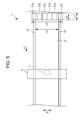
- Fig. 5 is a schematic plan view illustrating the recording apparatus according to the third embodiment of the invention. It is to be noted that the same reference numerals denote the same constituent components as those in the above-mentioned embodiments and detail description thereof is omitted.
- a recording apparatus 1 according to the embodiment is different from the recording apparatus 1 according to the first embodiment in a point that a length of a pressure portion at a contact portion with the recording target medium P in the scanning direction B can be varied in accordance with the length of the recording target medium P in the scanning direction B.
- the recording apparatus 1 has a configuration in which the pressure portion is constituted by pressure portions 21a to 21f serving as contact portions.
- the pressure portions 21a to 21f are so configured as to be capable of being detached with respect to base shafts (not illustrated) in the scanning direction B or moving to positions at which they do not make contact with the recording target medium P.
- the length of the pressure portion at the contact portion in the scanning direction B can be varied in accordance with the length of the recording target medium P in use in the scanning direction B.
- the pressure portions 21a to 21f have movement mechanisms (not illustrated) that are movable in the scanning direction B.
- This configuration can suppress transportation failure of the recording target medium P, and damage to the recording target medium P, the adhesive belt 10, and the pressure portions 21a to 21f, which can be caused by the contact between the pressure portions 21a to 21f and the adhesive belt 10.
- the upstream sides and the downstream sides of the pressure portions 21a to 21f in the transportation direction A are chamfered in the embodiment.
- the movement mechanisms (not illustrated) of the pressure portions make it possible to move the pressure portions 21a to 21f so as for the respective pressure portions to make contact with or be separated from the adhesive belt 10.
- a length L1 of the pressure portions 21a to 21f at the contact portion with the recording target medium P in the transportation direction A is equal to or larger than the transportation distance A1 of the recording target medium P in one-time transportation corresponding to the reciprocating scanning of the recording head 7.
- a length L2 of the pressure portions 21a to 21f at the contact portion with the recording target medium P in the scanning direction B is equal to or larger than the length L3 of the recording target medium P in the scanning direction B.
- the recording apparatus 1 according to the embodiment has a configuration capable of suppressing generation of thickness unevenness of the recording target medium P, thereby suppressing color unevenness of the recorded image because of the reasons same as those in the recording apparatus 1 according to the first embodiment.
- Fig. 6 is a schematic plan view illustrating the recording apparatus according to the fourth embodiment of the invention. It is to be noted that the same reference numerals denote the same constituent components as those in the above-mentioned embodiments and detail description thereof is omitted.
- a recording apparatus 1 according to the embodiment has a plurality of recording modes.
- the recording apparatus 1 can perform recording while varying the transportation distance of the recording target medium in one-time intermittent transportation from among transportation distances A1 to A3 respectively corresponding to the plurality of recording modes.
- the recording apparatus 1 according to the embodiment is different from the recording apparatus 1 according to the first embodiment in a point that a length of a pressure portion at a contact portion with the recording target medium P in the transportation direction A can be varied in accordance with the transportation distance of the recording target medium in the one-time intermittent transportation.
- the recording apparatus 1 has a configuration in which the pressure portion is constituted by pressure portions 21g to 21i serving as contact portions.
- the pressure portions 21g to 21i are so configured as to be capable of being detached with respect to base shafts (not illustrated) in the transportation direction A and moving to positions at which they do not make contact with the recording target medium P.
- the length of the pressure portion at the contact portion in the transportation direction A can be varied in accordance with the transportation distances A1 to A3 of the recording target medium P in the one-time intermittent transportation. To be specific, when the transportation distance of the recording target medium in the one-time intermittent transportation is the transportation distance A1, the length of the pressure portion in the transportation direction A can be set to a length L1 by the pressure portion 21g.
- the length of the pressure portion in the transportation direction A can be set to a length L4 by the pressure portion 21g and the pressure portion 21h. Further, when the transportation distance of the recording target medium in the one-time intermittent transportation is the transportation distance A3, the length of the pressure portion in the transportation direction A can be set to a length L5 by the pressure portion 21g, the pressure portion 21h, and the pressure portion 21i.
- the pressure portions 21g to 21i have movement mechanisms (not illustrated) that are movable in the transportation direction A.
- This configuration can suppress transportation failure of the recording target medium P, and damage to the recording target medium P, the adhesive belt 10, and the pressure portions 21g to 21i, which can be caused by the contact between the pressure portions 21g to 21i and the adhesive belt 10.
- the upstream sides and the downstream sides of the pressure portions 21g to 21i in the transportation direction A are chamfered in the embodiment.
- the movement mechanisms (not illustrated) of the pressure portions make it possible to move the pressure portions 21g to 21i so as for the respective pressure portions to make contact with or be separated from the adhesive belt 10.
- a length L2 of the pressure portions 21g to 21i at the contact portion with the recording target medium P in the scanning direction B is equal to or larger than the length L3 of the recording target medium P in the scanning direction B.
- the recording apparatus 1 according to the embodiment has a configuration capable of suppressing generation of thickness unevenness of the recording target medium P, thereby suppressing color unevenness of the recorded image because of the reasons same as those in the recording apparatus 1 according to the first embodiment.
Landscapes
- Ink Jet (AREA)
- Handling Of Sheets (AREA)
- Handling Of Continuous Sheets Of Paper (AREA)
- Delivering By Means Of Belts And Rollers (AREA)
- Advancing Webs (AREA)
- Registering, Tensioning, Guiding Webs, And Rollers Therefor (AREA)
- Folding Of Thin Sheet-Like Materials, Special Discharging Devices, And Others (AREA)
- Auxiliary Devices For And Details Of Packaging Control (AREA)
Abstract
Description
- The present invention relates to a recording apparatus including a transportation mechanism that transports a recording target medium placed on a movable belt.
- Recording apparatuses including a transportation mechanism that transports a recording target medium placed on a movable belt have been used. Disclosed is a recording apparatus including an adhesive belt as the movable belt among the recording apparatuses. The adhesive belt is a belt whose surface is coated with an adhesive that adheres to and holds a recording target medium placed thereon in a separable manner.
- For example,
JP-A-11-192694 - In the recording apparatus including the adhesive belt, in general, a pressure portion formed by a pressure roller or the like is provided for attaching the recording target medium to the adhesive belt without generating wrinkles, floating, or the like.
- In a recording apparatus that causes a recording head to make reciprocating scanning in a direction intersecting with a transportation direction of a recording target medium and discharge ink so as to perform recording, it is necessary to transport the recording target medium so as to correspond to the reciprocating scanning of the recording head. Therefore, the transportation of the recording target medium is intermittent transportation.
- However, in the recording apparatus having the configuration in which the pressure portion formed by the pressure roller or the like is provided, the transportation of the recording target medium generates a portion (portion that is pressed by the pressure portion in a stopped state of the medium) to which a longer pressing time by the pressure portion is given and a portion (portion that is pressed by the pressure portion only in a moving state of the medium) to which a shorter pressing time by the pressure portion is given on the recording target medium with the intermittent transportation. Therefore, the thickness of the recording target medium on the portion to which the longer pressing time by the pressure portion is given is smaller than that on the portion to which the shorter pressing time by the pressure portion is given. Due to this, unevenness is generated in the thickness of the recording target medium on the adhesive belt in some cases. In addition, color unevenness is also generated in a recorded image formed on the recording target medium due to the thickness unevenness of the recording target medium in some cases. The color unevenness in the recorded image is particularly prominent on a surface of a fabric at the side opposite to the recording surface when the fabric is used as the recording target medium, but can be also recognized clearly on the recording surface in some cases.
- As far as the recording apparatus disclosed in
JP-A-11-192694 - An advantage of some aspects of the invention is to suppress color unevenness in a recorded image by suppressing thickness unevenness of a recording target medium, which is generated by pressing the recording target medium and attaching it to an adhesive belt.
- A recording apparatus according to a first aspect of the invention includes a transportation mechanism that has an adhesive belt on which a recording target medium is placed and is capable of transporting the recording target medium intermittently, a pressure portion that attaches the recording target medium to the adhesive belt, and a recording mechanism that performs recording on the recording target medium. In the recording apparatus, a length of the pressure portion at a contact portion with the recording target medium in a transportation direction of the recording target medium is equal to or larger than a transportation distance of the recording target medium in one-time intermittent transportation when recording is performed on the recording target medium.
- The expression "transportation distance of the recording target medium in one-time intermittent transportation when recording is performed on the recording target medium" has the following meaning. In the recording apparatus that causes a recording head to make reciprocating scanning in the scanning direction intersecting with the transportation direction of the recording target medium so as to perform recording, the transportation mechanism stops the transportation of the recording target medium during recording scanning (during movement of the recording head). In another expression, the reciprocating scanning of the recording head and the transportation of the recording target medium are alternately performed when the recording is performed. The above-mentioned expression indicates a transportation distance per transportation of the recording target medium, which is performed alternately.
- According to the aspect of the invention, the length of the pressure portion at the contact portion with the recording target medium in the transportation direction is equal to or larger than the transportation distance of the recording target medium in one-time transportation corresponding to the reciprocating scanning of the recording head. Therefore, when the recording target medium is transported intermittently at the time of the recording, any portion of the recording target medium is pressed by the pressure portion in a state where the recording medium stops in the transportation direction. In another expression, no portion of the recording target medium is pressed by the pressure portion only in the movement state thereof.
- Therefore, all the portions of the recording target medium in the transportation direction receive equal to or larger than a certain pressing force. This can suppress generation of thickness unevenness of the recording target medium, thereby suppressing color unevenness of a recorded image.
- In the recording apparatus according to a second aspect of the invention, it is preferable in the first aspect of the invention that the length of the pressure portion at the contact portion with the recording target medium in the transportation direction be capable of being varied in accordance with the transportation distance of the recording target medium in the one-time intermittent transportation.
- According to the aspect of the invention, the length of the pressure portion at the contact portion with the recording target medium in the transportation direction is capable of being varied in accordance with the transportation distance of the recording target medium in the one-time intermittent transportation. Therefore, in a recording apparatus that is capable of varying the transportation distance of the recording target medium in the one-time intermittent transportation, transportation failure of the recording target medium, and damage to the recording target medium, the adhesive belt, and the pressure portion, which can be caused due to the contact between the pressure portion and the adhesive belt, can be suppressed.
- As a specific configuration of varying the length of the pressure portion at the contact portion in the transportation direction, for example, the following configuration or the like is included. That is, a plurality of members constituting the contact portion are provided on the pressure portion so as to be detached or moved to positions at which those members do not make contact with the recording target medium in the transportation direction, then a user can detach or move all or a part of the members in accordance with the transportation distance of the recording target medium in the one-time intermittent transportation.
- In the recording apparatus according to a third aspect of the invention, it is preferable in the first or second aspect of the invention that a length of the pressure portion at the contact portion with the recording target medium in a scanning direction be equal to or larger than a length of the recording target medium in the scanning direction.
- According to the aspect of the invention, the recording target medium overall in the scanning direction intersecting with the transportation direction can be pressed. That is to say, the recording target medium can be pressed on a wide contact surface. This can suppress generation of the thickness unevenness of the recording target medium, thereby suppressing color unevenness of the recorded image.
- In the recording apparatus according to a fourth aspect of the invention, it is preferable in the third aspect of the invention that the length of the pressure portion at the contact portion with the recording target medium in the scanning direction be capable of being varied in accordance with the length of the recording target medium in the scanning direction.
- According to the aspect of the invention, the length of the pressure portion at the contact portion in the scanning direction is capable of being varied in accordance with the length of the recording target medium in the scanning direction. Therefore, transportation failure of the recording target medium, and damage to the recording target medium, the adhesive belt, and the pressure portion, which can be caused due to the contact between the pressure portion and the adhesive belt, can be suppressed.
- As a specific configuration of varying the length of the pressure portion at the contact portion in the scanning direction, for example, the following configuration or the like is included. That is, a plurality of members constituting the contact portion are provided on the pressure portion so as to be detached or moved to positions at which those members do not make contact with the recording target medium in the scanning direction, then a user can detach or move all or a part of the members in accordance with the recording target medium that is used.
- In the recording apparatus according to a fifth aspect of the invention, it is preferable in any one of the first to fourth aspects of the invention that an upstream side of the pressure portion in the transportation direction be chamfered at the contact portion with the recording target medium.
- According to the aspect of the invention, the upstream side of the pressure portion in the transportation direction is chamfered at the contact portion. This suppresses a problem that the contact portion and the recording target medium interfere with each other to generate transportation failure of the recording target medium and give damage to at least one of the contact portion and the recording target medium when the recording target medium is transported.
- It is preferable in any one of the first to fifth aspects of the invention that the recording apparatus according to a sixth aspect of the invention further include a movement mechanism of the pressure portion by which the pressure portion is moved so as to make contact with or be separated from the adhesive belt.
- According to the aspect of the invention, when the recording target medium is placed on the adhesive belt, the recording target medium can be pressed in the following manner. That is, the pressure portion is separated from the adhesive belt once and a front end of the recording target medium is placed on the adhesive belt. Thereafter, the pressure portion is made closer to the adhesive belt so as to press the recording target medium. Therefore, operability when the recording target medium is placed on the adhesive belt is improved.
- Embodiments of the invention will now be described by way of example only with reference to the accompanying drawings, wherein like numbers reference like elements.
-
Fig. 1 is a schematic side view illustrating a recording apparatus according to a first embodiment of the invention. -
Fig. 2 is a schematic plan view illustrating the recording apparatus according to the first embodiment of the invention. -
Fig. 3 is a schematic side view illustrating a recording apparatus according to a second embodiment of the invention. -
Fig. 4 is a schematic plan view illustrating the recording apparatus according to the second embodiment of the invention. -
Fig. 5 is a schematic plan view illustrating a recording apparatus according to a third embodiment of the invention. -
Fig. 6 is a schematic plan view illustrating a recording apparatus according to a fourth embodiment of the invention. - Hereinafter, recording apparatuses according to embodiments of the invention are described in detail with reference to the accompanying drawings.
- First, described is a recording apparatus according to a first embodiment of the invention.
-
Fig. 1 is a schematic side view illustrating arecording apparatus 1 according to the first embodiment of the invention. - The
recording apparatus 1 according to the embodiment includes a set portion 2 that can feed out a roll R1 of a recording target medium P for recording. Therecording apparatus 1 further includes apressure portion 12 and atransportation mechanism 3. Thepressure portion 12 presses the recording target medium P against anadhesive belt 10 as a movable belt and attaches the recording target medium P thereto. Thetransportation mechanism 3 transports the recording target medium P in a transportation direction A by theadhesive belt 10. In addition, therecording apparatus 1 includes arecording mechanism 4 that causes arecording head 7 to make reciprocating scanning in a scanning direction B intersecting with the transportation direction A of the recording target medium P so as to perform recording. Moreover, therecording apparatus 1 includes acleaning mechanism 15 for theadhesive belt 10. Therecording apparatus 1 further includes a wind-up mechanism 18 having a wind-upshaft 17 and acutter 16. The wind-upshaft 17 winds up the recording target medium P. Thecutter 16 cuts the wound-up recording target medium P. - The set portion 2 includes a
rotating shaft 5 that also serves as a set position of the roll R1 of the recording target medium P for recording. The set portion 2 has a configuration capable of feeding out the recording target medium P to thetransportation mechanism 3 from the roll R1 set on therotating shaft 5 through a drivenroller 6. It is to be noted that therotating shaft 5 rotates in a rotating direction C when the recording target medium P is fed out to thetransportation mechanism 3. - The
transportation mechanism 3 includes theadhesive belt 10 and atransportation roller 8 and a drivenroller 9. The recording target medium P fed out from the set portion 2 is placed on theadhesive belt 10 so as to be transported. Thetransportation roller 8 and the drivenroller 9 move theadhesive belt 10. The recording target medium P is pressed against and attached to theadhesive belt 10 by thepressure portion 12 so as to be placed thereon. It is to be noted that thetransportation roller 8 rotates in the rotating direction C when the recording target medium P is transported. - The upstream side and the downstream side of the
pressure portion 12 at a contact portion with the recording target medium P in the transportation direction A are chamfered. This suppresses a problem that the contact portion and the recording target medium P interfere with each other to generate transportation failure of the recording target medium P and give damage to at least one of the contact portion and the recording target medium P when the recording target medium P is transported. - Further, a movement mechanism (not illustrated) of the
pressure portion 12 makes it possible to move thepressure portion 12 so as to make contact with or be separated from theadhesive belt 10. Therefore, when the recording target medium P is placed on theadhesive belt 10, the recording target medium P can be pressed in the following manner. That is, thepressure portion 12 is separated from theadhesive belt 10 once and the front end of the recording target medium P is placed on theadhesive belt 10. Thereafter, thepressure portion 12 is made closer to theadhesive belt 10 so as to press the recording target medium P. That is to say, operability when the recording target medium P is placed on theadhesive belt 10 is preferable. - The
recording mechanism 4 includes therecording head 7, a carriage (not illustrated), and a carriage motor (not illustrated). Therecording head 7 is mounted on the carriage. The carriage motor causes the carriage to reciprocate in a scanning direction B. The scanning direction B is a direction perpendicular to the paper plane inFig. 1 . - When recording is performed, the
recording head 7 is caused to make reciprocating scanning so as to perform recording. During the recording scanning (during movement of the recording head), thetransportation mechanism 3 stops transportation of the recording target medium P. In another expression, the reciprocating scanning of therecording head 7 and the transportation of the recording target medium P are alternately performed when the recording is performed. That is to say, thetransportation mechanism 3 transports the recording target medium P intermittently so as to correspond to the reciprocating scanning of therecording head 7 when the recording is performed. - The
cleaning mechanism 15 for theadhesive belt 10 includes acleaning unit 13 and atray 14. Thecleaning unit 13 is configured by coupling a plurality of cleaning rollers in a rotating shaft direction. Thetray 14 accommodates a cleaner as a cleaning mechanism of thecleaning unit 13. - The wind-
up mechanism 18 is a mechanism for winding up the recording target medium P on which recording has been performed and which has been transported from thetransportation mechanism 3 through a drivenroller 11. The wind-up mechanism 18 can wind up the recording target medium P as a roll R2 by setting a paper tube or the like for medium-winding on the wind-upshaft 17 and winding the recording target medium P around the paper tube. - The
recording apparatus 1 according to the embodiment includes thepressure portion 12 of which length L1 at the contact portion with the recording target medium P in the transportation direction A is equal to or larger than a transportation distance A1 of the recording target medium P in one-time transportation corresponding to the reciprocating scanning of therecording head 7. That is to say, thepressure portion 12 has a configuration capable of suppressing generation of thickness unevenness of the recording target medium P depending on the pressing time against the recording target medium P following the intermittent transportation of the recording target medium P. - The
pressure portion 20 in the embodiment is constituted by a single member. However, thepressure portion 20 may have a configuration in which a plurality of members are aligned in the transportation direction A so as to make the length L1 of thepressure portion 20 at the contact portion with the recording target medium P in the transportation direction A be equal to or larger than the transportation distance A1. -
Fig. 2 is a schematic plan view illustrating therecording apparatus 1 according to the embodiment. - The
recording apparatus 1 according to the embodiment includes thepressure portion 12 of which length L2 at the contact portion with the recording target medium P in the scanning direction B is equal to or larger than a length L3 of the recording target medium P in the scanning direction B. Therefore, the recording target medium P can be pressed overall in the scanning direction B. That is to say, thepressure portion 12 can press the recording target medium P on a wide contact surface. This can suppress generation of the thickness unevenness of the recording target medium P, thereby suppressing color unevenness of the recorded image. - Next, described is a recording apparatus according to a second embodiment of the invention.
-
Fig. 3 is a schematic side view illustrating the recording apparatus according to the second embodiment of the invention.Fig. 4 is a schematic plan view illustrating the recording apparatus according to the second embodiment of the invention. It is to be noted that the same reference numerals denote the same constituent components as those in the above-mentioned embodiment and detail description thereof is omitted. - A
recording apparatus 1 according to the embodiment is different from therecording apparatus 1 according to the first embodiment in a point that a pressure portion is constituted by two members including acontact member 19 in contact with the recording target medium P and aweight 20. - In the same manner as in the
pressure portion 12 in the first embodiment, the upstream side and the downstream side of thecontact member 19 in contact with the recording target medium P in the transportation direction A are chamfered in the embodiment. A movement mechanism (not illustrated) of the pressure portion makes it possible to move the pressure portion constituted by thecontact member 19 in contact with the recording target medium P and theweight 20 so as to make contact with or be separated from theadhesive belt 10. Further, a length L1 of thecontact member 19 in contact with the recording target medium P at the contact portion with the recording target medium P in the transportation direction A is equal to or larger than the transportation distance A1 of the recording target medium P in one-time transportation corresponding to the reciprocating scanning of therecording head 7. A length L2 of thecontact member 19 in contact with the recording target medium P at the contact portion with the recording target medium P in the scanning direction B is equal to or larger than the length L3 of the recording target medium P in the scanning direction B. - Therefore, the
recording apparatus 1 according to the embodiment has a configuration capable of suppressing generation of thickness unevenness of the recording target medium P, thereby suppressing color unevenness of the recorded image because of the reasons same as those in therecording apparatus 1 according to the first embodiment. - Described is a recording apparatus according to a third embodiment of the invention.
-
Fig. 5 is a schematic plan view illustrating the recording apparatus according to the third embodiment of the invention. It is to be noted that the same reference numerals denote the same constituent components as those in the above-mentioned embodiments and detail description thereof is omitted. - A
recording apparatus 1 according to the embodiment is different from therecording apparatus 1 according to the first embodiment in a point that a length of a pressure portion at a contact portion with the recording target medium P in the scanning direction B can be varied in accordance with the length of the recording target medium P in the scanning direction B. - The
recording apparatus 1 according to the embodiment has a configuration in which the pressure portion is constituted bypressure portions 21a to 21f serving as contact portions. Thepressure portions 21a to 21f are so configured as to be capable of being detached with respect to base shafts (not illustrated) in the scanning direction B or moving to positions at which they do not make contact with the recording target medium P. The length of the pressure portion at the contact portion in the scanning direction B can be varied in accordance with the length of the recording target medium P in use in the scanning direction B. - The
pressure portions 21a to 21f have movement mechanisms (not illustrated) that are movable in the scanning direction B. - This configuration can suppress transportation failure of the recording target medium P, and damage to the recording target medium P, the
adhesive belt 10, and thepressure portions 21a to 21f, which can be caused by the contact between thepressure portions 21a to 21f and theadhesive belt 10. - In the same manner as in the
pressure portion 12 in the first embodiment, the upstream sides and the downstream sides of thepressure portions 21a to 21f in the transportation direction A are chamfered in the embodiment. The movement mechanisms (not illustrated) of the pressure portions make it possible to move thepressure portions 21a to 21f so as for the respective pressure portions to make contact with or be separated from theadhesive belt 10. A length L1 of thepressure portions 21a to 21f at the contact portion with the recording target medium P in the transportation direction A is equal to or larger than the transportation distance A1 of the recording target medium P in one-time transportation corresponding to the reciprocating scanning of therecording head 7. A length L2 of thepressure portions 21a to 21f at the contact portion with the recording target medium P in the scanning direction B is equal to or larger than the length L3 of the recording target medium P in the scanning direction B. - Therefore, the
recording apparatus 1 according to the embodiment has a configuration capable of suppressing generation of thickness unevenness of the recording target medium P, thereby suppressing color unevenness of the recorded image because of the reasons same as those in therecording apparatus 1 according to the first embodiment. - Next, described is a recording apparatus according to a fourth embodiment of the invention.
-
Fig. 6 is a schematic plan view illustrating the recording apparatus according to the fourth embodiment of the invention. It is to be noted that the same reference numerals denote the same constituent components as those in the above-mentioned embodiments and detail description thereof is omitted. - A
recording apparatus 1 according to the embodiment has a plurality of recording modes. Therecording apparatus 1 can perform recording while varying the transportation distance of the recording target medium in one-time intermittent transportation from among transportation distances A1 to A3 respectively corresponding to the plurality of recording modes. Therecording apparatus 1 according to the embodiment is different from therecording apparatus 1 according to the first embodiment in a point that a length of a pressure portion at a contact portion with the recording target medium P in the transportation direction A can be varied in accordance with the transportation distance of the recording target medium in the one-time intermittent transportation. - The
recording apparatus 1 according to the embodiment has a configuration in which the pressure portion is constituted bypressure portions 21g to 21i serving as contact portions. Thepressure portions 21g to 21i are so configured as to be capable of being detached with respect to base shafts (not illustrated) in the transportation direction A and moving to positions at which they do not make contact with the recording target medium P. The length of the pressure portion at the contact portion in the transportation direction A can be varied in accordance with the transportation distances A1 to A3 of the recording target medium P in the one-time intermittent transportation. To be specific, when the transportation distance of the recording target medium in the one-time intermittent transportation is the transportation distance A1, the length of the pressure portion in the transportation direction A can be set to a length L1 by thepressure portion 21g. When the transportation distance of the recording target medium in the one-time intermittent transportation is the transportation distance A2, the length of the pressure portion in the transportation direction A can be set to a length L4 by thepressure portion 21g and thepressure portion 21h. Further, when the transportation distance of the recording target medium in the one-time intermittent transportation is the transportation distance A3, the length of the pressure portion in the transportation direction A can be set to a length L5 by thepressure portion 21g, thepressure portion 21h, and thepressure portion 21i. - The
pressure portions 21g to 21i have movement mechanisms (not illustrated) that are movable in the transportation direction A. - This configuration can suppress transportation failure of the recording target medium P, and damage to the recording target medium P, the
adhesive belt 10, and thepressure portions 21g to 21i, which can be caused by the contact between thepressure portions 21g to 21i and theadhesive belt 10. - In the same manner as in the
pressure portion 12 in the first embodiment, the upstream sides and the downstream sides of thepressure portions 21g to 21i in the transportation direction A are chamfered in the embodiment. The movement mechanisms (not illustrated) of the pressure portions make it possible to move thepressure portions 21g to 21i so as for the respective pressure portions to make contact with or be separated from theadhesive belt 10. A length L2 of thepressure portions 21g to 21i at the contact portion with the recording target medium P in the scanning direction B is equal to or larger than the length L3 of the recording target medium P in the scanning direction B. - Therefore, the
recording apparatus 1 according to the embodiment has a configuration capable of suppressing generation of thickness unevenness of the recording target medium P, thereby suppressing color unevenness of the recorded image because of the reasons same as those in therecording apparatus 1 according to the first embodiment. - The foregoing description has been given by way of example only and it will be appreciated by a person skilled in the art that modifications can be made without departing from the scope of the present invention.
Claims (6)
- A recording apparatus comprising:a transportation mechanism that has an adhesive belt on which a recording target medium is placed and is capable of transporting the recording target medium intermittently;a pressure portion that attaches the recording target medium to the adhesive belt; anda recording mechanism that performs recording on the recording target medium,wherein a length of the pressure portion at a contact portion with the recording target medium in a transportation direction of the recording target medium is equal to or larger than a transportation distance of the recording target medium in one-time intermittent transportation when recording is performed on the recording target medium.
- The recording apparatus according to Claim 1,
wherein the length of the pressure portion at the contact portion with the recording target medium in the transportation direction is capable of being varied in accordance with the transportation distance of the recording target medium in the one-time intermittent transportation. - The recording apparatus according to Claim 1,
wherein a length of the pressure portion at the contact portion with the recording target medium in a scanning direction is equal to or larger than a length of the recording target medium in the scanning direction. - The recording apparatus according to Claim 3,
wherein the length of the pressure portion at the contact portion with the recording target medium in the scanning direction is capable of being varied in accordance with the length of the recording target medium in the scanning direction. - The recording apparatus according to Claim 1,
wherein an upstream side of the pressure portion in the transportation direction is chamfered at the contact portion with the recording target medium. - The recording apparatus according to Claim 1,
further comprising a movement mechanism of the pressure portion by which the pressure portion is moved so as to make contact with or be separated from the adhesive belt.
Applications Claiming Priority (2)
| Application Number | Priority Date | Filing Date | Title |
|---|---|---|---|
| JP2013002539 | 2013-01-10 | ||
| JP2013243737A JP6274399B2 (en) | 2013-01-10 | 2013-11-26 | Recording device |
Publications (2)
| Publication Number | Publication Date |
|---|---|
| EP2754560A1 true EP2754560A1 (en) | 2014-07-16 |
| EP2754560B1 EP2754560B1 (en) | 2018-03-14 |
Family
ID=49911437
Family Applications (1)
| Application Number | Title | Priority Date | Filing Date |
|---|---|---|---|
| EP14150773.1A Active EP2754560B1 (en) | 2013-01-10 | 2014-01-10 | Recording apparatus |
Country Status (3)
| Country | Link |
|---|---|
| EP (1) | EP2754560B1 (en) |
| JP (1) | JP6274399B2 (en) |
| TR (1) | TR201807254T4 (en) |
Cited By (3)
| Publication number | Priority date | Publication date | Assignee | Title |
|---|---|---|---|---|
| US10059125B2 (en) | 2016-02-19 | 2018-08-28 | Seiko Epson Corporation | Recording appartus with support unit supporting medium transport belt |
| EP3403833A1 (en) * | 2017-05-19 | 2018-11-21 | Seiko Epson Corporation | Printing apparatus |
| CN112549773A (en) * | 2019-09-25 | 2021-03-26 | 精工爱普生株式会社 | Recording apparatus |
Citations (6)
| Publication number | Priority date | Publication date | Assignee | Title |
|---|---|---|---|---|
| JPH11192694A (en) | 1997-12-29 | 1999-07-21 | Canon Inc | Ink jet printer |
| US20020054781A1 (en) * | 2000-11-07 | 2002-05-09 | Aharon Korem | Method for environmentally-friendly textile transportation in printing systems and a system thereof cross-reference to related applications |
| WO2006125239A1 (en) * | 2005-05-25 | 2006-11-30 | Durst Phototechnik Digital Technology Gmbh | Locating device for an ink-jet printer |
| JP2006327156A (en) * | 2005-05-30 | 2006-12-07 | Canon Finetech Inc | Ink jet recording apparatus |
| US20090167833A1 (en) * | 2007-12-28 | 2009-07-02 | Seiko Epson Corporation | Ink jet textile printing apparatus |
| EP2669094A1 (en) * | 2012-05-31 | 2013-12-04 | La Meccanica Costruzione Macchine Tessili S.p.A. | Printer for fabric |
Family Cites Families (5)
| Publication number | Priority date | Publication date | Assignee | Title |
|---|---|---|---|---|
| JPH07133035A (en) * | 1993-07-28 | 1995-05-23 | Canon Inc | Ink jet recording device and method |
| JP2794266B2 (en) * | 1994-07-14 | 1998-09-03 | 株式会社バルダン縫製機器 | Continuous printing machine for long cloth |
| JP3285458B2 (en) * | 1994-12-26 | 2002-05-27 | キヤノン株式会社 | Sheet transport device and printer having sheet transport device |
| JPH1120972A (en) * | 1997-07-03 | 1999-01-26 | Canon Inc | Sheet feeding device and image processing device |
| JP5157808B2 (en) * | 2007-12-28 | 2013-03-06 | セイコーエプソン株式会社 | Inkjet printing device |
-
2013
- 2013-11-26 JP JP2013243737A patent/JP6274399B2/en not_active Expired - Fee Related
-
2014
- 2014-01-10 TR TR2018/07254T patent/TR201807254T4/en unknown
- 2014-01-10 EP EP14150773.1A patent/EP2754560B1/en active Active
Patent Citations (6)
| Publication number | Priority date | Publication date | Assignee | Title |
|---|---|---|---|---|
| JPH11192694A (en) | 1997-12-29 | 1999-07-21 | Canon Inc | Ink jet printer |
| US20020054781A1 (en) * | 2000-11-07 | 2002-05-09 | Aharon Korem | Method for environmentally-friendly textile transportation in printing systems and a system thereof cross-reference to related applications |
| WO2006125239A1 (en) * | 2005-05-25 | 2006-11-30 | Durst Phototechnik Digital Technology Gmbh | Locating device for an ink-jet printer |
| JP2006327156A (en) * | 2005-05-30 | 2006-12-07 | Canon Finetech Inc | Ink jet recording apparatus |
| US20090167833A1 (en) * | 2007-12-28 | 2009-07-02 | Seiko Epson Corporation | Ink jet textile printing apparatus |
| EP2669094A1 (en) * | 2012-05-31 | 2013-12-04 | La Meccanica Costruzione Macchine Tessili S.p.A. | Printer for fabric |
Cited By (6)
| Publication number | Priority date | Publication date | Assignee | Title |
|---|---|---|---|---|
| US10059125B2 (en) | 2016-02-19 | 2018-08-28 | Seiko Epson Corporation | Recording appartus with support unit supporting medium transport belt |
| EP3403833A1 (en) * | 2017-05-19 | 2018-11-21 | Seiko Epson Corporation | Printing apparatus |
| CN108944084A (en) * | 2017-05-19 | 2018-12-07 | 精工爱普生株式会社 | Printing equipment |
| CN108944084B (en) * | 2017-05-19 | 2021-11-19 | 精工爱普生株式会社 | Printing device |
| CN112549773A (en) * | 2019-09-25 | 2021-03-26 | 精工爱普生株式会社 | Recording apparatus |
| CN112549773B (en) * | 2019-09-25 | 2023-05-16 | 精工爱普生株式会社 | Recording device |
Also Published As
| Publication number | Publication date |
|---|---|
| EP2754560B1 (en) | 2018-03-14 |
| JP2014148157A (en) | 2014-08-21 |
| TR201807254T4 (en) | 2018-06-21 |
| JP6274399B2 (en) | 2018-02-07 |
Similar Documents
| Publication | Publication Date | Title |
|---|---|---|
| EP2689934A1 (en) | Image forming apparatus and image forming method | |
| US9315045B2 (en) | Image forming apparatus configured for rolled printing media having adhesive face | |
| EP2754560A1 (en) | Recording apparatus | |
| EP3047974A2 (en) | Head unit and recording apparatus | |
| CN105269984A (en) | Conveyor device and inkjet recording apparatus | |
| JP6703300B2 (en) | Recording device | |
| US9145278B2 (en) | Medium transportation device and recording apparatus | |
| JP6264537B2 (en) | Recording apparatus and recording method | |
| EP2756957B1 (en) | Recordng apparatus and recording method | |
| JP2016049640A (en) | Label printer and stage | |
| CN107097540B (en) | Recording apparatus | |
| JP6687879B2 (en) | Medium transport device | |
| JP2012166867A (en) | Recording device | |
| JP2007062045A (en) | Cutting device, recorder equipped with cutting device, and cutting method of sheet-like member | |
| JP2020033122A (en) | Printing device | |
| US9498989B2 (en) | Recording apparatus | |
| EP3042780A1 (en) | Recording device | |
| US20150274484A1 (en) | Conveying device | |
| JP2016150805A (en) | Sheet carrier device and printing equipment | |
| JP2016124674A (en) | Printer and label peeling device | |
| JP5888398B2 (en) | Recording device | |
| JP2011088723A (en) | Method of manufacturing conveying roller, and conveying unit and printing device | |
| JP2014040015A (en) | Take-up device, and recording device | |
| JP2014043003A (en) | Take-up device, and image recording device | |
| JP2016030352A (en) | Liquid discharge device and tube fixing method |
Legal Events
| Date | Code | Title | Description |
|---|---|---|---|
| PUAI | Public reference made under article 153(3) epc to a published international application that has entered the european phase |
Free format text: ORIGINAL CODE: 0009012 |
|
| 17P | Request for examination filed |
Effective date: 20140110 |
|
| AK | Designated contracting states |
Kind code of ref document: A1 Designated state(s): AL AT BE BG CH CY CZ DE DK EE ES FI FR GB GR HR HU IE IS IT LI LT LU LV MC MK MT NL NO PL PT RO RS SE SI SK SM TR |
|
| AX | Request for extension of the european patent |
Extension state: BA ME |
|
| R17P | Request for examination filed (corrected) |
Effective date: 20141114 |
|
| RBV | Designated contracting states (corrected) |
Designated state(s): AL AT BE BG CH CY CZ DE DK EE ES FI FR GB GR HR HU IE IS IT LI LT LU LV MC MK MT NL NO PL PT RO RS SE SI SK SM TR |
|
| 17Q | First examination report despatched |
Effective date: 20160204 |
|
| GRAP | Despatch of communication of intention to grant a patent |
Free format text: ORIGINAL CODE: EPIDOSNIGR1 |
|
| STAA | Information on the status of an ep patent application or granted ep patent |
Free format text: STATUS: GRANT OF PATENT IS INTENDED |
|
| INTG | Intention to grant announced |
Effective date: 20171006 |
|
| GRAS | Grant fee paid |
Free format text: ORIGINAL CODE: EPIDOSNIGR3 |
|
| GRAA | (expected) grant |
Free format text: ORIGINAL CODE: 0009210 |
|
| STAA | Information on the status of an ep patent application or granted ep patent |
Free format text: STATUS: THE PATENT HAS BEEN GRANTED |
|
| AK | Designated contracting states |
Kind code of ref document: B1 Designated state(s): AL AT BE BG CH CY CZ DE DK EE ES FI FR GB GR HR HU IE IS IT LI LT LU LV MC MK MT NL NO PL PT RO RS SE SI SK SM TR |
|
| REG | Reference to a national code |
Ref country code: GB Ref legal event code: FG4D |
|
| REG | Reference to a national code |
Ref country code: CH Ref legal event code: EP Ref country code: AT Ref legal event code: REF Ref document number: 978471 Country of ref document: AT Kind code of ref document: T Effective date: 20180315 |
|
| REG | Reference to a national code |
Ref country code: IE Ref legal event code: FG4D |
|
| REG | Reference to a national code |
Ref country code: DE Ref legal event code: R096 Ref document number: 602014022235 Country of ref document: DE |
|
| REG | Reference to a national code |
Ref country code: NL Ref legal event code: MP Effective date: 20180314 |
|
| REG | Reference to a national code |
Ref country code: LT Ref legal event code: MG4D |
|
| PG25 | Lapsed in a contracting state [announced via postgrant information from national office to epo] |
Ref country code: HR Free format text: LAPSE BECAUSE OF FAILURE TO SUBMIT A TRANSLATION OF THE DESCRIPTION OR TO PAY THE FEE WITHIN THE PRESCRIBED TIME-LIMIT Effective date: 20180314 Ref country code: FI Free format text: LAPSE BECAUSE OF FAILURE TO SUBMIT A TRANSLATION OF THE DESCRIPTION OR TO PAY THE FEE WITHIN THE PRESCRIBED TIME-LIMIT Effective date: 20180314 Ref country code: NO Free format text: LAPSE BECAUSE OF FAILURE TO SUBMIT A TRANSLATION OF THE DESCRIPTION OR TO PAY THE FEE WITHIN THE PRESCRIBED TIME-LIMIT Effective date: 20180614 Ref country code: CY Free format text: LAPSE BECAUSE OF FAILURE TO SUBMIT A TRANSLATION OF THE DESCRIPTION OR TO PAY THE FEE WITHIN THE PRESCRIBED TIME-LIMIT Effective date: 20180314 Ref country code: LT Free format text: LAPSE BECAUSE OF FAILURE TO SUBMIT A TRANSLATION OF THE DESCRIPTION OR TO PAY THE FEE WITHIN THE PRESCRIBED TIME-LIMIT Effective date: 20180314 |
|
| REG | Reference to a national code |
Ref country code: AT Ref legal event code: MK05 Ref document number: 978471 Country of ref document: AT Kind code of ref document: T Effective date: 20180314 |
|
| PG25 | Lapsed in a contracting state [announced via postgrant information from national office to epo] |
Ref country code: LV Free format text: LAPSE BECAUSE OF FAILURE TO SUBMIT A TRANSLATION OF THE DESCRIPTION OR TO PAY THE FEE WITHIN THE PRESCRIBED TIME-LIMIT Effective date: 20180314 Ref country code: RS Free format text: LAPSE BECAUSE OF FAILURE TO SUBMIT A TRANSLATION OF THE DESCRIPTION OR TO PAY THE FEE WITHIN THE PRESCRIBED TIME-LIMIT Effective date: 20180314 Ref country code: SE Free format text: LAPSE BECAUSE OF FAILURE TO SUBMIT A TRANSLATION OF THE DESCRIPTION OR TO PAY THE FEE WITHIN THE PRESCRIBED TIME-LIMIT Effective date: 20180314 Ref country code: BG Free format text: LAPSE BECAUSE OF FAILURE TO SUBMIT A TRANSLATION OF THE DESCRIPTION OR TO PAY THE FEE WITHIN THE PRESCRIBED TIME-LIMIT Effective date: 20180614 Ref country code: GR Free format text: LAPSE BECAUSE OF FAILURE TO SUBMIT A TRANSLATION OF THE DESCRIPTION OR TO PAY THE FEE WITHIN THE PRESCRIBED TIME-LIMIT Effective date: 20180615 |
|
| PG25 | Lapsed in a contracting state [announced via postgrant information from national office to epo] |
Ref country code: AL Free format text: LAPSE BECAUSE OF FAILURE TO SUBMIT A TRANSLATION OF THE DESCRIPTION OR TO PAY THE FEE WITHIN THE PRESCRIBED TIME-LIMIT Effective date: 20180314 Ref country code: RO Free format text: LAPSE BECAUSE OF FAILURE TO SUBMIT A TRANSLATION OF THE DESCRIPTION OR TO PAY THE FEE WITHIN THE PRESCRIBED TIME-LIMIT Effective date: 20180314 Ref country code: ES Free format text: LAPSE BECAUSE OF FAILURE TO SUBMIT A TRANSLATION OF THE DESCRIPTION OR TO PAY THE FEE WITHIN THE PRESCRIBED TIME-LIMIT Effective date: 20180314 Ref country code: EE Free format text: LAPSE BECAUSE OF FAILURE TO SUBMIT A TRANSLATION OF THE DESCRIPTION OR TO PAY THE FEE WITHIN THE PRESCRIBED TIME-LIMIT Effective date: 20180314 Ref country code: PL Free format text: LAPSE BECAUSE OF FAILURE TO SUBMIT A TRANSLATION OF THE DESCRIPTION OR TO PAY THE FEE WITHIN THE PRESCRIBED TIME-LIMIT Effective date: 20180314 Ref country code: NL Free format text: LAPSE BECAUSE OF FAILURE TO SUBMIT A TRANSLATION OF THE DESCRIPTION OR TO PAY THE FEE WITHIN THE PRESCRIBED TIME-LIMIT Effective date: 20180314 |
|
| PG25 | Lapsed in a contracting state [announced via postgrant information from national office to epo] |
Ref country code: SM Free format text: LAPSE BECAUSE OF FAILURE TO SUBMIT A TRANSLATION OF THE DESCRIPTION OR TO PAY THE FEE WITHIN THE PRESCRIBED TIME-LIMIT Effective date: 20180314 Ref country code: SK Free format text: LAPSE BECAUSE OF FAILURE TO SUBMIT A TRANSLATION OF THE DESCRIPTION OR TO PAY THE FEE WITHIN THE PRESCRIBED TIME-LIMIT Effective date: 20180314 Ref country code: CZ Free format text: LAPSE BECAUSE OF FAILURE TO SUBMIT A TRANSLATION OF THE DESCRIPTION OR TO PAY THE FEE WITHIN THE PRESCRIBED TIME-LIMIT Effective date: 20180314 Ref country code: AT Free format text: LAPSE BECAUSE OF FAILURE TO SUBMIT A TRANSLATION OF THE DESCRIPTION OR TO PAY THE FEE WITHIN THE PRESCRIBED TIME-LIMIT Effective date: 20180314 |
|
| REG | Reference to a national code |
Ref country code: DE Ref legal event code: R097 Ref document number: 602014022235 Country of ref document: DE |
|
| PG25 | Lapsed in a contracting state [announced via postgrant information from national office to epo] |
Ref country code: PT Free format text: LAPSE BECAUSE OF FAILURE TO SUBMIT A TRANSLATION OF THE DESCRIPTION OR TO PAY THE FEE WITHIN THE PRESCRIBED TIME-LIMIT Effective date: 20180716 |
|
| PLBE | No opposition filed within time limit |
Free format text: ORIGINAL CODE: 0009261 |
|
| STAA | Information on the status of an ep patent application or granted ep patent |
Free format text: STATUS: NO OPPOSITION FILED WITHIN TIME LIMIT |
|
| PG25 | Lapsed in a contracting state [announced via postgrant information from national office to epo] |
Ref country code: DK Free format text: LAPSE BECAUSE OF FAILURE TO SUBMIT A TRANSLATION OF THE DESCRIPTION OR TO PAY THE FEE WITHIN THE PRESCRIBED TIME-LIMIT Effective date: 20180314 |
|
| 26N | No opposition filed |
Effective date: 20181217 |
|
| PG25 | Lapsed in a contracting state [announced via postgrant information from national office to epo] |
Ref country code: SI Free format text: LAPSE BECAUSE OF FAILURE TO SUBMIT A TRANSLATION OF THE DESCRIPTION OR TO PAY THE FEE WITHIN THE PRESCRIBED TIME-LIMIT Effective date: 20180314 |
|
| PG25 | Lapsed in a contracting state [announced via postgrant information from national office to epo] |
Ref country code: MC Free format text: LAPSE BECAUSE OF FAILURE TO SUBMIT A TRANSLATION OF THE DESCRIPTION OR TO PAY THE FEE WITHIN THE PRESCRIBED TIME-LIMIT Effective date: 20180314 |
|
| REG | Reference to a national code |
Ref country code: CH Ref legal event code: PL |
|
| GBPC | Gb: european patent ceased through non-payment of renewal fee |
Effective date: 20190110 |
|
| PG25 | Lapsed in a contracting state [announced via postgrant information from national office to epo] |
Ref country code: LU Free format text: LAPSE BECAUSE OF NON-PAYMENT OF DUE FEES Effective date: 20190110 |
|
| REG | Reference to a national code |
Ref country code: BE Ref legal event code: MM Effective date: 20190131 |
|
| REG | Reference to a national code |
Ref country code: IE Ref legal event code: MM4A |
|
| PG25 | Lapsed in a contracting state [announced via postgrant information from national office to epo] |
Ref country code: BE Free format text: LAPSE BECAUSE OF NON-PAYMENT OF DUE FEES Effective date: 20190131 |
|
| PG25 | Lapsed in a contracting state [announced via postgrant information from national office to epo] |
Ref country code: CH Free format text: LAPSE BECAUSE OF NON-PAYMENT OF DUE FEES Effective date: 20190131 Ref country code: LI Free format text: LAPSE BECAUSE OF NON-PAYMENT OF DUE FEES Effective date: 20190131 Ref country code: GB Free format text: LAPSE BECAUSE OF NON-PAYMENT OF DUE FEES Effective date: 20190110 |
|
| PG25 | Lapsed in a contracting state [announced via postgrant information from national office to epo] |
Ref country code: IE Free format text: LAPSE BECAUSE OF NON-PAYMENT OF DUE FEES Effective date: 20190110 |
|
| PGFP | Annual fee paid to national office [announced via postgrant information from national office to epo] |
Ref country code: IT Payment date: 20200114 Year of fee payment: 7 |
|
| PG25 | Lapsed in a contracting state [announced via postgrant information from national office to epo] |
Ref country code: MT Free format text: LAPSE BECAUSE OF NON-PAYMENT OF DUE FEES Effective date: 20190110 |
|
| PGFP | Annual fee paid to national office [announced via postgrant information from national office to epo] |
Ref country code: FR Payment date: 20201210 Year of fee payment: 8 |
|
| PGFP | Annual fee paid to national office [announced via postgrant information from national office to epo] |
Ref country code: TR Payment date: 20210107 Year of fee payment: 8 Ref country code: DE Payment date: 20201229 Year of fee payment: 8 |
|
| PG25 | Lapsed in a contracting state [announced via postgrant information from national office to epo] |
Ref country code: IS Free format text: LAPSE BECAUSE OF FAILURE TO SUBMIT A TRANSLATION OF THE DESCRIPTION OR TO PAY THE FEE WITHIN THE PRESCRIBED TIME-LIMIT Effective date: 20180714 |
|
| PG25 | Lapsed in a contracting state [announced via postgrant information from national office to epo] |
Ref country code: HU Free format text: LAPSE BECAUSE OF FAILURE TO SUBMIT A TRANSLATION OF THE DESCRIPTION OR TO PAY THE FEE WITHIN THE PRESCRIBED TIME-LIMIT; INVALID AB INITIO Effective date: 20140110 |
|
| PG25 | Lapsed in a contracting state [announced via postgrant information from national office to epo] |
Ref country code: IT Free format text: LAPSE BECAUSE OF NON-PAYMENT OF DUE FEES Effective date: 20210110 |
|
| PG25 | Lapsed in a contracting state [announced via postgrant information from national office to epo] |
Ref country code: MK Free format text: LAPSE BECAUSE OF FAILURE TO SUBMIT A TRANSLATION OF THE DESCRIPTION OR TO PAY THE FEE WITHIN THE PRESCRIBED TIME-LIMIT Effective date: 20180314 |
|
| REG | Reference to a national code |
Ref country code: DE Ref legal event code: R119 Ref document number: 602014022235 Country of ref document: DE |
|
| PG25 | Lapsed in a contracting state [announced via postgrant information from national office to epo] |
Ref country code: DE Free format text: LAPSE BECAUSE OF NON-PAYMENT OF DUE FEES Effective date: 20220802 |
|
| PG25 | Lapsed in a contracting state [announced via postgrant information from national office to epo] |
Ref country code: FR Free format text: LAPSE BECAUSE OF NON-PAYMENT OF DUE FEES Effective date: 20220131 |