EP3403003B1 - Boîte de vitesses de véhicule automobile devant être montée longitudinalement dans un véhicule automobile - Google Patents
Boîte de vitesses de véhicule automobile devant être montée longitudinalement dans un véhicule automobile Download PDFInfo
- Publication number
- EP3403003B1 EP3403003B1 EP17700046.0A EP17700046A EP3403003B1 EP 3403003 B1 EP3403003 B1 EP 3403003B1 EP 17700046 A EP17700046 A EP 17700046A EP 3403003 B1 EP3403003 B1 EP 3403003B1
- Authority
- EP
- European Patent Office
- Prior art keywords
- gear
- motor vehicle
- gear set
- transmission
- gear stage
- Prior art date
- Legal status (The legal status is an assumption and is not a legal conclusion. Google has not performed a legal analysis and makes no representation as to the accuracy of the status listed.)
- Active
Links
Images

Classifications
-
- F—MECHANICAL ENGINEERING; LIGHTING; HEATING; WEAPONS; BLASTING
- F16—ENGINEERING ELEMENTS AND UNITS; GENERAL MEASURES FOR PRODUCING AND MAINTAINING EFFECTIVE FUNCTIONING OF MACHINES OR INSTALLATIONS; THERMAL INSULATION IN GENERAL
- F16H—GEARING
- F16H3/00—Toothed gearings for conveying rotary motion with variable gear ratio or for reversing rotary motion
- F16H3/02—Toothed gearings for conveying rotary motion with variable gear ratio or for reversing rotary motion without gears having orbital motion
- F16H3/08—Toothed gearings for conveying rotary motion with variable gear ratio or for reversing rotary motion without gears having orbital motion exclusively or essentially with continuously meshing gears, that can be disengaged from their shafts
- F16H3/087—Toothed gearings for conveying rotary motion with variable gear ratio or for reversing rotary motion without gears having orbital motion exclusively or essentially with continuously meshing gears, that can be disengaged from their shafts characterised by the disposition of the gears
- F16H3/091—Toothed gearings for conveying rotary motion with variable gear ratio or for reversing rotary motion without gears having orbital motion exclusively or essentially with continuously meshing gears, that can be disengaged from their shafts characterised by the disposition of the gears including a single countershaft
- F16H3/0915—Toothed gearings for conveying rotary motion with variable gear ratio or for reversing rotary motion without gears having orbital motion exclusively or essentially with continuously meshing gears, that can be disengaged from their shafts characterised by the disposition of the gears including a single countershaft with coaxial input and output shafts
-
- F—MECHANICAL ENGINEERING; LIGHTING; HEATING; WEAPONS; BLASTING
- F16—ENGINEERING ELEMENTS AND UNITS; GENERAL MEASURES FOR PRODUCING AND MAINTAINING EFFECTIVE FUNCTIONING OF MACHINES OR INSTALLATIONS; THERMAL INSULATION IN GENERAL
- F16H—GEARING
- F16H57/00—General details of gearing
- F16H57/02—Gearboxes; Mounting gearing therein
- F16H57/033—Series gearboxes, e.g. gearboxes based on the same design being available in different sizes or gearboxes using a combination of several standardised units
- F16H2057/0335—Series transmissions of modular design, e.g. providing for different transmission ratios or power ranges
-
- F—MECHANICAL ENGINEERING; LIGHTING; HEATING; WEAPONS; BLASTING
- F16—ENGINEERING ELEMENTS AND UNITS; GENERAL MEASURES FOR PRODUCING AND MAINTAINING EFFECTIVE FUNCTIONING OF MACHINES OR INSTALLATIONS; THERMAL INSULATION IN GENERAL
- F16H—GEARING
- F16H2200/00—Transmissions for multiple ratios
- F16H2200/003—Transmissions for multiple ratios characterised by the number of forward speeds
- F16H2200/0052—Transmissions for multiple ratios characterised by the number of forward speeds the gear ratios comprising six forward speeds
-
- F—MECHANICAL ENGINEERING; LIGHTING; HEATING; WEAPONS; BLASTING
- F16—ENGINEERING ELEMENTS AND UNITS; GENERAL MEASURES FOR PRODUCING AND MAINTAINING EFFECTIVE FUNCTIONING OF MACHINES OR INSTALLATIONS; THERMAL INSULATION IN GENERAL
- F16H—GEARING
- F16H2200/00—Transmissions for multiple ratios
- F16H2200/003—Transmissions for multiple ratios characterised by the number of forward speeds
- F16H2200/0056—Transmissions for multiple ratios characterised by the number of forward speeds the gear ratios comprising seven forward speeds
Definitions
- the present invention relates to a motor vehicle transmission for longitudinal installation in a motor vehicle, having an input shaft arrangement which can be connected to an output member of a clutch arrangement; an output shaft that can be connected to drive wheels or to a differential; a countershaft arranged in parallel with the input shaft assembly; a plurality of gear sets for setting up gear stages, the gear sets each being mounted on two of the shafts and being shiftable by means of respective clutches which are at least partially combined into clutch packs; a housing in which the shafts and the wheel sets are received; and a bearing arrangement for supporting the shafts on the housing, which is designed so that a first variant and a second variant of the motor vehicle transmission can be constructed with this bearing arrangement, the motor vehicle transmission in the first variant can be constructed with a first number of forward gear stages and in the second variant can be built with these forward gear stages and a further forward gear stage.
- Such motor vehicle transmissions are known for example from DE 10 2005 005 338 B3 .
- These known transmissions are so-called inline transmissions, that is to say transmissions for longitudinal installation in a motor vehicle.
- the transmissions can be set up in such a way that they can be shifted manually by means of a classic shift gate, that is to say that clutch packs shift adjacent gears.
- these known transmissions can be constructed as an automatic transmission with a further forward gear.
- Gearboxes are sometimes specially developed and built to meet customer requirements. A lot of work and development is required, so that the production of customer-specific gearboxes in small series is hardly economically viable.
- the EP 1 122 463 A2 discloses a modular motor vehicle transmission which falls under the wording of the preamble of claim 1.
- the object of the invention is to provide an improved and economical inline transmission with which as many different embodiments as possible, that is to say special customer requests, can be realized.
- the torque loads on the countershaft are lower than in the case of a drive constant gear set, so that the teeth of the gear sets can be made narrower.
- the transmission can generally be in be made shorter in the axial direction.
- the loads on the clutches are lower, which means that shorter switching times can be achieved.
- the invention results in a mounting of the output shaft with a favorable contact pattern, with a very rigid mounting of the output constant gear set being achieved. In addition, there is usually a favorable bearing load.
- gear cover of the housing and / or the bearing plate can be made from identical parts in both variants and are preferably identical.
- a reverse gear set is the gear set closest to an input of the motor vehicle transmission and can be actuated by means of a reverse gear clutch which is arranged on the side of the reverse gear gear set facing the transmission input, wherein in the second variant, a gear set for the further forward gear is arranged on the side of a reverse gear clutch facing the transmission input, the reverse gear clutch being integrated with another clutch for the further gear in a clutch pack.
- the second variant of the inline transmission is also axially short.
- the additional forward gear of the second variant can be implemented in a structurally favorable manner.
- the following components are arranged axially one behind the other in the first variant, viewed from a transmission input: a reverse gear shift clutch, a reverse gear gear set, a gear set for gear position 1, a clutch pack for gear steps 1 and 2, a gear set for gear position 2 , a gear set for gear position 5, a clutch pack for gear positions 5 and 6, a gear set for gear position 6, a gear set for gear position 3, a clutch pack for gear positions 3 and 4, and a constant output gear set.
- This advantageous vehicle transmission arrangement makes it possible to shift the motor vehicle transmission with an H shift gate, with shift rods being connectable directly to shift forks, whereby the actuation direction of a clutch does not have to be deflected / reversed.
- the transmission can therefore be shifted mechanically in a simple manner.
- the following components are arranged axially one behind the other in the second variant, viewed from a transmission input: a gear set for gear stage 7, a clutch pack for gear stage 7 and reverse gear stage R, a reverse gear stage gear set, a gear set for gear stage 1, a Clutch package for gear steps 1 and 2, a gear set for gear position 2, a gear set for gear position 4, a gear set for gear positions 4 and 3, a gear set for gear position 3, a gear set for gear position 6, a clutch pack for gear positions 6 and 5, and a Output constant gear set.
- This advantageous gear set layout makes it possible to design the transmission in the second variant, i.e. with 7 gear steps, in such a way that it can be shifted manually by means of an H shift gate, since the clutch packs shift adjacent gear steps.
- At least one clutch pack can be actuated by means of a shift fork and / or at least one clutch pack can be actuated by means of a rocker switch.
- the actuation can take place in each case by means of a switching rod or, for example, by means of a cable control and driver device or coupling piece.
- a rocker switch is mounted on a deflection axis (deflection device) aligned transversely to the shift rod in such a way that when actuated (for example by means of a shift rod) in a first axial direction through the deflection device, the shifting clutch packet assigned to the rocker switch is axially opposite to the first direction Direction is shifted.
- the clutch pack for gears 1/2 is shifted by means of a shift fork and the clutch packs for gears 4/3 and 6/5 can be shifted using respective rocker switches.
- gear set layout of the second variant can also be designed to be manually switchable in a structurally simple manner.
- gear set for gear stage 1 the reverse gear gear set and preferably the gear set for gear stage 2 are formed by identical parts in both variants.
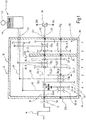
- Fig. 1 shows a motor vehicle transmission 10 in a drive train 12 shown schematically.
- a drive motor 14 is shown schematically as an internal combustion engine. It goes without saying that an electric motor, a hybrid unit or other known drive motors can also be used.
- the drive motor 14 can be connected to an input of the motor vehicle transmission 10 via a clutch arrangement 16. When the clutch arrangement 16 is closed, an input shaft 18 of the motor vehicle transmission 10 is driven by the drive motor 14. An output shaft of the motor vehicle transmission is denoted by 20.
- the input shaft 18 is arranged parallel to a countershaft 22 of the motor vehicle transmission 10 and is connected to the countershaft 22 by several gear sets, each of which has at least one idler gear 24 and one fixed gear 26.
- the countershaft 22 is connected in a rotationally fixed manner to the output shaft 20, the output shaft 20 being connected via a differential 28 or directly to the drive wheels 30R, 30L.
- the input shaft 18, the output shaft 20 and the countershaft 22 are each supported by bearing assemblies 32.
- the individual gear stages can each be inserted by means of shift clutches 36, the corresponding idler gear 24 being connected to the corresponding shaft 18, 22 in a rotationally fixed manner by the insertion of a shift clutch 36.
- the transmission has an output constant gear set 38.
- the drive power is thus transmitted from the countershaft 22 to the output shaft 20 via a gear pair consisting of two fixed gears.
- a manual H-shift device which is generally designated 40 and has a shift lever 42 which is displaceable in a shift gate 44 and can, for example, operate shift forks 46 via shift rods 48.
- the gear steps that can be shifted with the respective gear sets are in Fig. 1 and Fig. 2 indicated below the wheelsets.
- the in Fig. 1 The variant shown is the 4th gear set up as a direct corridor.
- the 5th gear is set up as a direct gear.
- the third highest gear is set up as a direct gear.
- a high spread of the transmission 10 is thereby possible.
- a direct gear is understood to mean that the input shaft 18 is non-rotatably connected to the output shaft 20 without an intermediate transmission.
- the transmission 10 has a transmission input 50 through which drive power can be introduced into the transmission 10.
- the transmission 10 further has a transmission output 52 via which drive power can be transmitted from the transmission 10 to the differential 28 or directly to the drive wheels 30R, 30L.
- the transmission 10 further has a transmission housing 54, the transmission housing 54 having a housing pot 55, a bearing plate 56 and a housing cover 58.
- the countershaft 22 is supported by a total of three bearings 32b, 32e, 32g on the transmission input 50, the bearing plate 56 and the housing cover 58.
- the output shaft 20 is supported on the housing cover 58 by the bearing 32f and is preferably additionally supported in or on the input shaft 18, which is shown in FIG Fig. 1 is not shown in detail.
- the input shaft 18 and the output shaft 20 are arranged coaxially.
- the input shaft 18 is supported by two bearings 32a, 32d, the bearing 32a being arranged on the transmission input and the bearing 32d being arranged on the bearing plate 56.
- the output shaft 20 can also be mounted on the input shaft 18.
- the output shaft 20 is supported by two bearings 32d, 32e, the bearing 32e being arranged on the transmission output 52 and the bearing 32d being arranged on the bearing plate 56.
- the bearing plate 56 is arranged in such a way that the output constant gear set 38 and a further gear set 24/26 for a gear stage are arranged between the transmission output 52 and the bearing plate 56.
- the clutches 36 can also be actuated via a rocker switch 60.
- a rocker switch 60 is mounted on a deflection device 62 in such a way that when a
- the gear stage 1 is set up by a fixed gear 64 arranged on the input shaft 18 which meshes with an idler gear 24-1 arranged on the countershaft 22.
- the fixed gear 64 is also in engagement with a direction reversing gear 66, which in turn engages with an idler gear 24 -R arranged on the countershaft 22 in order to set up the reverse gear -R.
- the gear stage 2 is also set up via a fixed gear 26-2 arranged on the input shaft 18 which meshes with an idler gear 24-2 arranged on the countershaft 22.
- the gear stages 5 and 6 are each set up by idler gears 24-5, 24-6 arranged on the input shaft, which mesh with fixed gears 26-5, 26-6 arranged on the countershaft 22.
- the gear stage 3 is set up by an idler gear 24-3 arranged on the input shaft 18, which meshes with a fixed gear 26-3 arranged on the countershaft 22.
- Individual clutches 36 can preferably be combined in so-called clutch packs 70, whereby a clutch pack 70 can be shifted in a first axial direction in order to engage a first gear stage and in a second axial direction opposite to the first one in order to engage a second gear stage .
- gear stage 4 is designed as a direct gear stage.
- the transmission arrangement can be actuated with an H shift device 40, which is shown in FIG Fig. 1 is only shown schematically.
- the switching device can be actuated in a manner known per se and has a switching lever 42 which is movably arranged in a switching gate 44.
- a shift shaft 72 can be actuated in this way by the shift lever 42 be that a shift shaft 74 couples with one of the shift rods 48, so that when the shift lever 42 moves along a shift gate, the respective shift rod 48 is displaced in the axial direction.
- the shift rod 48 moves, for example via a shift fork 46 or a shift rocker 60, a shift sleeve of a shift clutch pack 70, so that a gear step is engaged or disengaged.
- Fig. 2 For a better overview, the switching device 40, the gear housing 54, the bearing plate 56 and parts of the drive train 12 are not shown.
- Fig. 2 shows schematically a gear set layout for a 7-speed variant.
- the clutches 36-7 and 36-R for the gear stage 7 and the reverse gear stage -R are combined to form a clutch pack 70a.
- the reverse gear is as in the in Fig. 1
- the variant shown is set up via the gear set pair 64/66/24-R, with a fixed gear 64 for gear stage 1 and the reverse gear stage being arranged on the transmission input shaft 18 and engaging with an idler gear 24-R via a direction reversing gear 66.
- the idler gear 24-R is arranged on the countershaft 22 and can be connected non-rotatably to the countershaft 22 by the clutch pack 70a.
- the gear sets of gears 1 and 2 and the reverse gear-R are preferably identical to those in the 6-gear variant, as in FIG Fig. 1 shown.
- the gear stages 4 and 3 are each set up by idler gears 24-4, 24-3 arranged on the input shaft, which mesh with fixed gears 26-4, 26-3 arranged on the countershaft 22.
- the gear stage 6 is set up by an idler gear 24-6 arranged on the input shaft 18, which meshes with a fixed gear 26-6 arranged on the countershaft 22.
- the clutch packs 70a and 70b are arranged on the countershaft 22 and the clutch packs 70c and 70d on the input shaft 18.
- the clutch pack 70a shifts the 7th gear and the reverse gear.
- the clutch pack 70b shifts the 1st gear stage and the 2nd gear stage.
- the clutch pack 70c shifts the 4th and 3rd gear and can be actuated by means of a rocker switch 60-1, which is arranged on a deflection device 62-1.
- the rocker switch 60-1 is actuated by a switch rod 48.
- the clutch 70d shifts the 6th and 5th gear.
- the 5th gear is set up as a direct gear.
- the clutch pack 70d can also be actuated by means of a rocker switch 60-2 arranged on a deflection device 62-2.
- gear steps which are arranged between the 2nd gear step and the transmission output 52, are interchangeable or can be arranged in any order, namely by arranging the gear sets 24/26 and clutches 36 or clutch packs 70 accordingly.
- the bearing plate 56 and the housing cover 58 are preferably identical parts or at least can be produced from the same base part.
- the center distance between the input shaft 18 or output shaft 20 and the countershaft 22 is the same in both variants and is preferably selected so that high torque ranges and spreads are also possible for the 6-speed variant.
- Both the 6-speed variant and the 7-speed variant can be used for vehicles with a diesel engine as well as for vehicles with a gasoline engine, the torque range preferably starting at 200 Nm and being able to reach up to 800 Nm, in particular in ranges from 400 Nm to 500 Nm can be.
- first variant and the second variant are shown as a manual transmission 10, it is also conceivable to provide an automated actuation of the transmission 10 without departing from the scope of the invention.
Landscapes
- Engineering & Computer Science (AREA)
- General Engineering & Computer Science (AREA)
- Mechanical Engineering (AREA)
- Structure Of Transmissions (AREA)
- Arrangement Of Transmissions (AREA)
- Hybrid Electric Vehicles (AREA)
Claims (8)
- Boîte de vitesses modulaire de véhicule automobile (10) devant être montée longitudinalement dans un véhicule automobile, comprenant- un agencement d'arbre d'entrée (18) qui peut être connecté à un organe de sortie (68) d'un agencement d'embrayage (16),- un arbre de sortie (20) qui peut être connecté à des roues d'entraînement (30R, 30L) ou à un différentiel (28),- un arbre intermédiaire (22) qui est disposé parallèlement à l'agencement d'arbre d'entrée (18),- une pluralité de jeux de pignons (24/26, 24/64/66, 64/24) pour configurer des rapports de vitesses (R ; 1 ; 2 ; 3 ; 4 ; 5 ; 6 ; 7), les jeux de pignons (24/26, 24/64/66, 64/24) étant à chaque fois supportés sur l'agencement d'arbre d'entrée (18) et l'arbre intermédiaire (22) et reliant ceux-ci l'un à l'autre et les jeux de pignons (24/26, 24/64/66, 64/24) présentant à chaque fois un pignon fixe (26, 26-2, 26-3, 26-4, 26-5, 26-6, 64) et un pignon fou (24, 24-1, 24-2, 24-3, 24-4, 24-5, 24-6, 24-R) et pouvant être commutés au moyen d'embrayages respectifs (36, 36-7, 36-R) pour configurer les rapports de vitesses (R ; 1 ; 2 ; 3 ; 4 ; 5 ; 6 ; 7), les embrayages étant au moins en partie réunis en paquets d'embrayages (70),- un boîtier (54) dans lequel sont reçus les arbres (18, 20, 22) et les jeux de pignons (24/26, 24/64/66, 64/24), et- un agencement de palier (32a, 32b, 32c, 32d, 32e, 32f, 32g) pour supporter les arbres (18, 20, 22) sur le boîtier (54), lequel est réalisé de telle sorte que l'on puisse construire avec cet agencement de palier (32a, 32b, 32c, 32d, 32e, 32f, 32g) dans la même mesure une première variante et une deuxième variante de la boîte de vitesses de véhicule automobile (10), la boîte de vitesses de véhicule automobile (10), dans la première variante, étant construite avec un premier nombre de rapports de vitesses de marche avant (1 ; 2 ; 3 ; 4 ; 5 ; 6) et, dans la deuxième variante, étant construite avec un rapport de vitesse de marche avant supplémentaire (7),
caractérisée en ce que
les jeux de pignons (24/26, 24/64/66, 64/24) et les embrayages associés et les paquets d'embrayages (70, 70a, 70b, 70c, 70d) dans les deux variantes sont choisis de telle sorte qu'un changement de vitesses manuelles soit possible de sorte que la boîte de vitesses de véhicule automobile (10) puisse être réalisée dans les deux variantes en tant que boîte de vitesses manuelles avec un dispositif de sélection de vitesses en H (40) qui n'est pas actionné de manière automatique, le dispositif de sélection de vitesses en H (40) présentant un levier de sélection (42) qui peut être déplacés dans une coulisse de changement de vitesses (44), l'arbre intermédiaire (22) et l'arbre de sortie (20) étant connectés l'un à l'autre par le biais d'un jeu de pignons à constante de prise de force (38), exclusivement le jeu de pignons à constante de prise de force (38) et précisément un jeu de pignons supplémentaire (24/26), vu dans la direction axiale, étant disposés dans les deux variantes entre un couvercle de boîte de vitesses (58) du côté de la sortie de la boîte de vitesses et un plateau de palier (56). - Boîte de vitesses modulaire de véhicule automobile (10) selon la revendication 1,
caractérisée en ce que dans les deux variantes, un rapport de vitesse direct (4, 5) est prévu. - Boîte de vitesses modulaire de véhicule automobile (10) selon la revendication 1 ou 2,
caractérisée en ce que le couvercle de boîte de vitesses (58) du boîtier (54) et/ou le plateau de palier (56) sont identiques dans les deux variantes. - Boîte de vitesses modulaire de véhicule automobile (10) selon la revendication 1, 2 ou 3, caractérisée en ce que dans la première variante, un jeu de pignons de rapport de vitesse de marche arrière (24-R/64/66) est le jeu de pignons (24-R/64/66) le plus proche d'une entrée (50) de la boîte de vitesses de véhicule automobile (10), et peut être actionné au moyen d'un embrayage de rapport de vitesse de marche arrière (36-R) qui est disposé du côté du jeu de pignons de rapport de vitesse de marche arrière (24-R/64/66) tourné vers l'entrée de la boîte de vitesses (50),
dans la deuxième variante, un jeu de pignons (24-7/26-7) pour le rapport de vitesse de marche avant supplémentaire (7) étant disposé du côté d'un embrayage de rapport de vitesse de marche arrière (36-R) tourné vers l'entrée de la boîte de vitesses (50), l'embrayage de rapport de vitesse de marche arrière (36-R) étant intégré avec un embrayage supplémentaire (36-7) pour le rapport de vitesse supplémentaire (7) dans un paquet d'embrayages (70a). - Boîte de vitesses modulaire de véhicule automobile (10) selon l'une quelconque des revendications 1 à 4,
caractérisée en ce que dans la première variante, les composants suivants sont disposés axialement les uns derrière les autres, vu à partir d'une entrée de la boîte de vitesses (50) : un embrayage de rapport de vitesse de marche arrière (36-R), un jeu de pignons de rapport de vitesse de marche arrière (24-R/64/66), un jeu de pignons (24-1/64) pour le rapport de vitesse 1, un paquet d'embrayages (70b) pour les rapports de vitesses 1 et 2, un jeu de pignons (24-2/26-2) pour le rapport de vitesse 2, un jeu de pignons (24-5/26-5) pour le rapport de vitesse 5, un paquet d'embrayages (70c) pour les rapports de vitesses 5 et 6, un jeu de pignons (24-6/26-6) pour le rapport de vitesse 6, un jeu de pignons (24-3/26-3) pour le rapport de vitesse 3, un paquet d'embrayages (70d) pour les rapports de vitesses 3 et 4, et le jeu de pignons à constante de prise de force (38). - Boîte de vitesses modulaire de véhicule automobile (10) selon l'une quelconque des revendications 1 à 5,
caractérisée en ce que dans la deuxième variante, les composants suivants sont disposés axialement les uns derrière les autres, vu à partir d'une entrée de la boîte de vitesses : un jeu de pignons (24-7/26-7) pour le rapport de vitesse 7, un paquet d'embrayages (70a) pour le rapport de vitesse 7 et pour le rapport de vitesse de marche arrière R, un jeu de pignons de rapport de vitesse de marche arrière (24-R/64/66), un jeu de pignons (24-1/64) pour le rapport de vitesse 1, un paquet d'embrayages (70b) pour les rapports de vitesses 1 et 2, un jeu de pignons (24-2/26-2) pour le rapport de vitesse 2, un jeu de pignons (24-4/26-4) pour le rapport de vitesse 4, un paquet d'embrayages (70c) pour les rapports de vitesses 4 et 3, un jeu de pignons (24-3/26-3) pour le rapport de vitesse 3, un jeu de pignons (24-6/26-6) pour le rapport de vitesse 6, un paquet d'embrayages (70d) pour les rapports de vitesses 6 et 5, et le jeu de pignons à constante de prise de force (38). - Boîte de vitesses modulaire de véhicule automobile (10) selon l'une quelconque des revendications 1 à 6,
caractérisée en ce qu'au moins un paquet d'embrayages (70) peut être actionné au moyen d'une fourchette de sélection (46) et/ou au moins un paquet d'embrayages (70) peut être actionné au moyen d'une bascule de sélection (60). - Boîte de vitesses modulaire de véhicule automobile (10) selon l'une quelconque des revendications 1 à 7,
caractérisée en ce qu'un jeu de pignons (24-1/64) pour le rapport de vitesse 1, un jeu de pignons de vitesse de marche arrière (24-R/64/66) et de préférence un jeu de pignons (24-2/26-2) pour le rapport de vitesse 2 sont formés dans les deux variantes par des pièces identiques.
Applications Claiming Priority (2)
| Application Number | Priority Date | Filing Date | Title |
|---|---|---|---|
| DE102016100475.8A DE102016100475A1 (de) | 2016-01-13 | 2016-01-13 | Kraftfahrzeuggetriebe für den Längseinbau in einem Kraftfahrzeug |
| PCT/EP2017/050105 WO2017121664A1 (fr) | 2016-01-13 | 2017-01-04 | Boîte de vitesses de véhicule automobile devant être montée longitudinalement dans un véhicule automobile |
Publications (2)
| Publication Number | Publication Date |
|---|---|
| EP3403003A1 EP3403003A1 (fr) | 2018-11-21 |
| EP3403003B1 true EP3403003B1 (fr) | 2020-09-02 |
Family
ID=57749961
Family Applications (1)
| Application Number | Title | Priority Date | Filing Date |
|---|---|---|---|
| EP17700046.0A Active EP3403003B1 (fr) | 2016-01-13 | 2017-01-04 | Boîte de vitesses de véhicule automobile devant être montée longitudinalement dans un véhicule automobile |
Country Status (4)
| Country | Link |
|---|---|
| EP (1) | EP3403003B1 (fr) |
| CN (1) | CN108474456B (fr) |
| DE (1) | DE102016100475A1 (fr) |
| WO (1) | WO2017121664A1 (fr) |
Families Citing this family (1)
| Publication number | Priority date | Publication date | Assignee | Title |
|---|---|---|---|---|
| CN108953537A (zh) * | 2018-08-03 | 2018-12-07 | 东南大学 | 一种模块化级联式变速器 |
Family Cites Families (11)
| Publication number | Priority date | Publication date | Assignee | Title |
|---|---|---|---|---|
| DE19959616A1 (de) * | 1999-12-10 | 2001-06-13 | Volkswagen Ag | Steuereinrichtung für ein automatisch und manuell schaltbares Schaltgetriebe in einem Kraftfahrzeug |
| GB2358680A (en) * | 2000-01-31 | 2001-08-01 | Eaton Corp | A transmission with low inertia shaft |
| JP4517694B2 (ja) * | 2004-03-22 | 2010-08-04 | 日産自動車株式会社 | ツインクラッチ式マニュアルトランスミッション |
| DE102005005338B3 (de) | 2005-01-27 | 2006-08-10 | Getrag Getriebe- Und Zahnradfabrik Hermann Hagenmeyer Gmbh & Cie Kg | Stufenwechselgetriebe |
| CN201487172U (zh) * | 2009-08-06 | 2010-05-26 | 浙江长泰机械有限公司 | 带主、副箱的中型汽车变速器 |
| CN102162504A (zh) * | 2010-07-12 | 2011-08-24 | 石铭正 | 电动车圆柱体变速箱 |
| DE102010055735A1 (de) * | 2010-12-22 | 2012-06-28 | Getrag Ford Transmissions Gmbh | Verfahren zur Modifizierung eines Schaltgetriebes |
| CN202032059U (zh) * | 2011-02-22 | 2011-11-09 | 长城汽车股份有限公司 | 横置五挡全同步机械变速器 |
| CN102230520A (zh) * | 2011-07-21 | 2011-11-02 | 安徽江淮汽车股份有限公司 | 手动换挡变速器的传动装置 |
| DE102012212910B4 (de) * | 2012-07-24 | 2020-02-06 | Bayerische Motoren Werke Aktiengesellschaft | Schalteinrichtung zum Schalten eines Getriebes |
| DE102014008044A1 (de) * | 2014-05-28 | 2015-12-03 | GM Global Technology Operations LLC (n. d. Ges. d. Staates Delaware) | Verfahren und Vorrichtung zum Unterstützen eines Fahrers eines Kraftfahrzeugs |
-
2016
- 2016-01-13 DE DE102016100475.8A patent/DE102016100475A1/de not_active Withdrawn
-
2017
- 2017-01-04 EP EP17700046.0A patent/EP3403003B1/fr active Active
- 2017-01-04 WO PCT/EP2017/050105 patent/WO2017121664A1/fr not_active Ceased
- 2017-01-04 CN CN201780006596.8A patent/CN108474456B/zh active Active
Also Published As
| Publication number | Publication date |
|---|---|
| CN108474456A (zh) | 2018-08-31 |
| EP3403003A1 (fr) | 2018-11-21 |
| DE102016100475A1 (de) | 2017-07-13 |
| CN108474456B (zh) | 2021-03-12 |
| WO2017121664A1 (fr) | 2017-07-20 |
Similar Documents
| Publication | Publication Date | Title |
|---|---|---|
| DE102004022413B4 (de) | Doppelkupplungsgetriebe | |
| EP2558745B1 (fr) | Train d'engrenages à double embrayage et procédé pour actionner un train d'engrenages à double embrayage | |
| EP2111514B1 (fr) | Boîte de vitesses à double embrayage d'un véhicule automobile | |
| EP1616116B1 (fr) | Boite de vitesses multi-etagee pour moteur a combustion interne | |
| EP1846669A1 (fr) | Transmission a double embrayage | |
| DE102011076382A1 (de) | Doppelkupplungsgetriebe | |
| EP3259500B1 (fr) | Boîte de vitesses à double embrayage pour véhicule à moteur | |
| DE4116189C2 (de) | Schaltgetriebe | |
| DE112006002161T5 (de) | Doppelvorgelege-Getriebe | |
| EP3180548B1 (fr) | Boîte de vitesses d'un véhicule automobile | |
| EP1740848A1 (fr) | Boite de vitesses a arbre de renvoi | |
| DE102011076381B4 (de) | Doppelkupplungsgetriebe | |
| EP2469125B1 (fr) | Boîte de vitesses automatique, notamment automatisée, pour un véhicule automobile | |
| EP1455116B1 (fr) | Boîte de vitesses compacte | |
| DE102009018450B4 (de) | Doppelkupplungsgetriebe | |
| DE4422901A1 (de) | Vielgängiges Stufenwechselgetriebe | |
| DE102009050151A1 (de) | Schaltvorrichtung zur Schaltung eines Doppelkupplungsgetriebes | |
| EP3403003B1 (fr) | Boîte de vitesses de véhicule automobile devant être montée longitudinalement dans un véhicule automobile | |
| DE2822617C2 (fr) | ||
| EP0595059B1 (fr) | Boîte de vitesses pour véhicule automobile | |
| EP1004795B1 (fr) | Boíte de vitesses avec un arbre intermédiaire, notamment pour véhicules automobiles | |
| DE102013005659A1 (de) | Schaltgetriebe für Kraftfahrzeuge | |
| DE10232835B4 (de) | Doppelkupplungsgetriebe | |
| EP1130291B1 (fr) | Concept pour transmission à arbres intermédiaires pour véhicules automobiles | |
| DE102013005644A1 (de) | Schaltgetriebe für Kraftfahrzeuge |
Legal Events
| Date | Code | Title | Description |
|---|---|---|---|
| STAA | Information on the status of an ep patent application or granted ep patent |
Free format text: STATUS: UNKNOWN |
|
| STAA | Information on the status of an ep patent application or granted ep patent |
Free format text: STATUS: THE INTERNATIONAL PUBLICATION HAS BEEN MADE |
|
| PUAI | Public reference made under article 153(3) epc to a published international application that has entered the european phase |
Free format text: ORIGINAL CODE: 0009012 |
|
| STAA | Information on the status of an ep patent application or granted ep patent |
Free format text: STATUS: REQUEST FOR EXAMINATION WAS MADE |
|
| 17P | Request for examination filed |
Effective date: 20180718 |
|
| AK | Designated contracting states |
Kind code of ref document: A1 Designated state(s): AL AT BE BG CH CY CZ DE DK EE ES FI FR GB GR HR HU IE IS IT LI LT LU LV MC MK MT NL NO PL PT RO RS SE SI SK SM TR |
|
| AX | Request for extension of the european patent |
Extension state: BA ME |
|
| DAV | Request for validation of the european patent (deleted) | ||
| DAX | Request for extension of the european patent (deleted) | ||
| RAP1 | Party data changed (applicant data changed or rights of an application transferred) |
Owner name: MAGNA PT B.V. & CO. KG |
|
| GRAP | Despatch of communication of intention to grant a patent |
Free format text: ORIGINAL CODE: EPIDOSNIGR1 |
|
| STAA | Information on the status of an ep patent application or granted ep patent |
Free format text: STATUS: GRANT OF PATENT IS INTENDED |
|
| INTG | Intention to grant announced |
Effective date: 20200515 |
|
| GRAS | Grant fee paid |
Free format text: ORIGINAL CODE: EPIDOSNIGR3 |
|
| GRAA | (expected) grant |
Free format text: ORIGINAL CODE: 0009210 |
|
| STAA | Information on the status of an ep patent application or granted ep patent |
Free format text: STATUS: THE PATENT HAS BEEN GRANTED |
|
| AK | Designated contracting states |
Kind code of ref document: B1 Designated state(s): AL AT BE BG CH CY CZ DE DK EE ES FI FR GB GR HR HU IE IS IT LI LT LU LV MC MK MT NL NO PL PT RO RS SE SI SK SM TR |
|
| REG | Reference to a national code |
Ref country code: GB Ref legal event code: FG4D Free format text: NOT ENGLISH |
|
| REG | Reference to a national code |
Ref country code: AT Ref legal event code: REF Ref document number: 1309181 Country of ref document: AT Kind code of ref document: T Effective date: 20200915 Ref country code: CH Ref legal event code: EP |
|
| REG | Reference to a national code |
Ref country code: DE Ref legal event code: R096 Ref document number: 502017007034 Country of ref document: DE |
|
| REG | Reference to a national code |
Ref country code: IE Ref legal event code: FG4D Free format text: LANGUAGE OF EP DOCUMENT: GERMAN |
|
| REG | Reference to a national code |
Ref country code: LT Ref legal event code: MG4D |
|
| PG25 | Lapsed in a contracting state [announced via postgrant information from national office to epo] |
Ref country code: SE Free format text: LAPSE BECAUSE OF FAILURE TO SUBMIT A TRANSLATION OF THE DESCRIPTION OR TO PAY THE FEE WITHIN THE PRESCRIBED TIME-LIMIT Effective date: 20200902 Ref country code: FI Free format text: LAPSE BECAUSE OF FAILURE TO SUBMIT A TRANSLATION OF THE DESCRIPTION OR TO PAY THE FEE WITHIN THE PRESCRIBED TIME-LIMIT Effective date: 20200902 Ref country code: GR Free format text: LAPSE BECAUSE OF FAILURE TO SUBMIT A TRANSLATION OF THE DESCRIPTION OR TO PAY THE FEE WITHIN THE PRESCRIBED TIME-LIMIT Effective date: 20201203 Ref country code: NO Free format text: LAPSE BECAUSE OF FAILURE TO SUBMIT A TRANSLATION OF THE DESCRIPTION OR TO PAY THE FEE WITHIN THE PRESCRIBED TIME-LIMIT Effective date: 20201202 Ref country code: LT Free format text: LAPSE BECAUSE OF FAILURE TO SUBMIT A TRANSLATION OF THE DESCRIPTION OR TO PAY THE FEE WITHIN THE PRESCRIBED TIME-LIMIT Effective date: 20200902 Ref country code: HR Free format text: LAPSE BECAUSE OF FAILURE TO SUBMIT A TRANSLATION OF THE DESCRIPTION OR TO PAY THE FEE WITHIN THE PRESCRIBED TIME-LIMIT Effective date: 20200902 Ref country code: BG Free format text: LAPSE BECAUSE OF FAILURE TO SUBMIT A TRANSLATION OF THE DESCRIPTION OR TO PAY THE FEE WITHIN THE PRESCRIBED TIME-LIMIT Effective date: 20201202 |
|
| REG | Reference to a national code |
Ref country code: NL Ref legal event code: MP Effective date: 20200902 |
|
| PG25 | Lapsed in a contracting state [announced via postgrant information from national office to epo] |
Ref country code: PL Free format text: LAPSE BECAUSE OF FAILURE TO SUBMIT A TRANSLATION OF THE DESCRIPTION OR TO PAY THE FEE WITHIN THE PRESCRIBED TIME-LIMIT Effective date: 20200902 Ref country code: LV Free format text: LAPSE BECAUSE OF FAILURE TO SUBMIT A TRANSLATION OF THE DESCRIPTION OR TO PAY THE FEE WITHIN THE PRESCRIBED TIME-LIMIT Effective date: 20200902 Ref country code: RS Free format text: LAPSE BECAUSE OF FAILURE TO SUBMIT A TRANSLATION OF THE DESCRIPTION OR TO PAY THE FEE WITHIN THE PRESCRIBED TIME-LIMIT Effective date: 20200902 |
|
| PG25 | Lapsed in a contracting state [announced via postgrant information from national office to epo] |
Ref country code: PT Free format text: LAPSE BECAUSE OF FAILURE TO SUBMIT A TRANSLATION OF THE DESCRIPTION OR TO PAY THE FEE WITHIN THE PRESCRIBED TIME-LIMIT Effective date: 20210104 Ref country code: RO Free format text: LAPSE BECAUSE OF FAILURE TO SUBMIT A TRANSLATION OF THE DESCRIPTION OR TO PAY THE FEE WITHIN THE PRESCRIBED TIME-LIMIT Effective date: 20200902 Ref country code: CZ Free format text: LAPSE BECAUSE OF FAILURE TO SUBMIT A TRANSLATION OF THE DESCRIPTION OR TO PAY THE FEE WITHIN THE PRESCRIBED TIME-LIMIT Effective date: 20200902 Ref country code: EE Free format text: LAPSE BECAUSE OF FAILURE TO SUBMIT A TRANSLATION OF THE DESCRIPTION OR TO PAY THE FEE WITHIN THE PRESCRIBED TIME-LIMIT Effective date: 20200902 Ref country code: SM Free format text: LAPSE BECAUSE OF FAILURE TO SUBMIT A TRANSLATION OF THE DESCRIPTION OR TO PAY THE FEE WITHIN THE PRESCRIBED TIME-LIMIT Effective date: 20200902 |
|
| PG25 | Lapsed in a contracting state [announced via postgrant information from national office to epo] |
Ref country code: AL Free format text: LAPSE BECAUSE OF FAILURE TO SUBMIT A TRANSLATION OF THE DESCRIPTION OR TO PAY THE FEE WITHIN THE PRESCRIBED TIME-LIMIT Effective date: 20200902 Ref country code: ES Free format text: LAPSE BECAUSE OF FAILURE TO SUBMIT A TRANSLATION OF THE DESCRIPTION OR TO PAY THE FEE WITHIN THE PRESCRIBED TIME-LIMIT Effective date: 20200902 Ref country code: IS Free format text: LAPSE BECAUSE OF FAILURE TO SUBMIT A TRANSLATION OF THE DESCRIPTION OR TO PAY THE FEE WITHIN THE PRESCRIBED TIME-LIMIT Effective date: 20210102 |
|
| REG | Reference to a national code |
Ref country code: DE Ref legal event code: R097 Ref document number: 502017007034 Country of ref document: DE |
|
| PG25 | Lapsed in a contracting state [announced via postgrant information from national office to epo] |
Ref country code: SK Free format text: LAPSE BECAUSE OF FAILURE TO SUBMIT A TRANSLATION OF THE DESCRIPTION OR TO PAY THE FEE WITHIN THE PRESCRIBED TIME-LIMIT Effective date: 20200902 |
|
| PLBE | No opposition filed within time limit |
Free format text: ORIGINAL CODE: 0009261 |
|
| STAA | Information on the status of an ep patent application or granted ep patent |
Free format text: STATUS: NO OPPOSITION FILED WITHIN TIME LIMIT |
|
| 26N | No opposition filed |
Effective date: 20210603 |
|
| PG25 | Lapsed in a contracting state [announced via postgrant information from national office to epo] |
Ref country code: MC Free format text: LAPSE BECAUSE OF FAILURE TO SUBMIT A TRANSLATION OF THE DESCRIPTION OR TO PAY THE FEE WITHIN THE PRESCRIBED TIME-LIMIT Effective date: 20200902 Ref country code: SI Free format text: LAPSE BECAUSE OF FAILURE TO SUBMIT A TRANSLATION OF THE DESCRIPTION OR TO PAY THE FEE WITHIN THE PRESCRIBED TIME-LIMIT Effective date: 20200902 Ref country code: DK Free format text: LAPSE BECAUSE OF FAILURE TO SUBMIT A TRANSLATION OF THE DESCRIPTION OR TO PAY THE FEE WITHIN THE PRESCRIBED TIME-LIMIT Effective date: 20200902 |
|
| REG | Reference to a national code |
Ref country code: CH Ref legal event code: PL |
|
| GBPC | Gb: european patent ceased through non-payment of renewal fee |
Effective date: 20210104 |
|
| PG25 | Lapsed in a contracting state [announced via postgrant information from national office to epo] |
Ref country code: LU Free format text: LAPSE BECAUSE OF NON-PAYMENT OF DUE FEES Effective date: 20210104 |
|
| REG | Reference to a national code |
Ref country code: BE Ref legal event code: MM Effective date: 20210131 |
|
| PG25 | Lapsed in a contracting state [announced via postgrant information from national office to epo] |
Ref country code: GB Free format text: LAPSE BECAUSE OF NON-PAYMENT OF DUE FEES Effective date: 20210104 Ref country code: LI Free format text: LAPSE BECAUSE OF NON-PAYMENT OF DUE FEES Effective date: 20210131 Ref country code: CH Free format text: LAPSE BECAUSE OF NON-PAYMENT OF DUE FEES Effective date: 20210131 |
|
| PG25 | Lapsed in a contracting state [announced via postgrant information from national office to epo] |
Ref country code: IE Free format text: LAPSE BECAUSE OF NON-PAYMENT OF DUE FEES Effective date: 20210104 |
|
| PG25 | Lapsed in a contracting state [announced via postgrant information from national office to epo] |
Ref country code: IS Free format text: LAPSE BECAUSE OF FAILURE TO SUBMIT A TRANSLATION OF THE DESCRIPTION OR TO PAY THE FEE WITHIN THE PRESCRIBED TIME-LIMIT Effective date: 20210102 |
|
| PG25 | Lapsed in a contracting state [announced via postgrant information from national office to epo] |
Ref country code: BE Free format text: LAPSE BECAUSE OF NON-PAYMENT OF DUE FEES Effective date: 20210131 |
|
| REG | Reference to a national code |
Ref country code: AT Ref legal event code: MM01 Ref document number: 1309181 Country of ref document: AT Kind code of ref document: T Effective date: 20220104 |
|
| PG25 | Lapsed in a contracting state [announced via postgrant information from national office to epo] |
Ref country code: AT Free format text: LAPSE BECAUSE OF NON-PAYMENT OF DUE FEES Effective date: 20220104 |
|
| PG25 | Lapsed in a contracting state [announced via postgrant information from national office to epo] |
Ref country code: NL Free format text: LAPSE BECAUSE OF NON-PAYMENT OF DUE FEES Effective date: 20200923 Ref country code: CY Free format text: LAPSE BECAUSE OF FAILURE TO SUBMIT A TRANSLATION OF THE DESCRIPTION OR TO PAY THE FEE WITHIN THE PRESCRIBED TIME-LIMIT Effective date: 20200902 |
|
| PG25 | Lapsed in a contracting state [announced via postgrant information from national office to epo] |
Ref country code: HU Free format text: LAPSE BECAUSE OF FAILURE TO SUBMIT A TRANSLATION OF THE DESCRIPTION OR TO PAY THE FEE WITHIN THE PRESCRIBED TIME-LIMIT; INVALID AB INITIO Effective date: 20170104 |
|
| PG25 | Lapsed in a contracting state [announced via postgrant information from national office to epo] |
Ref country code: MK Free format text: LAPSE BECAUSE OF FAILURE TO SUBMIT A TRANSLATION OF THE DESCRIPTION OR TO PAY THE FEE WITHIN THE PRESCRIBED TIME-LIMIT Effective date: 20200902 |
|
| PG25 | Lapsed in a contracting state [announced via postgrant information from national office to epo] |
Ref country code: MT Free format text: LAPSE BECAUSE OF FAILURE TO SUBMIT A TRANSLATION OF THE DESCRIPTION OR TO PAY THE FEE WITHIN THE PRESCRIBED TIME-LIMIT Effective date: 20200902 |
|
| PGFP | Annual fee paid to national office [announced via postgrant information from national office to epo] |
Ref country code: DE Payment date: 20250121 Year of fee payment: 9 |
|
| PGFP | Annual fee paid to national office [announced via postgrant information from national office to epo] |
Ref country code: FR Payment date: 20250127 Year of fee payment: 9 |
|
| PGFP | Annual fee paid to national office [announced via postgrant information from national office to epo] |
Ref country code: IT Payment date: 20250129 Year of fee payment: 9 |
|
| REG | Reference to a national code |
Ref country code: DE Ref legal event code: R082 Ref document number: 502017007034 Country of ref document: DE Representative=s name: EULER, MATTHIAS, DR., DE |
|
| REG | Reference to a national code |
Ref country code: DE Ref legal event code: R081 Ref document number: 502017007034 Country of ref document: DE Owner name: MAGNA PT B.V. & CO. KGAA, DE Free format text: FORMER OWNER: MAGNA PT B.V. & CO. KG, 74199 UNTERGRUPPENBACH, DE |
|
| PG25 | Lapsed in a contracting state [announced via postgrant information from national office to epo] |
Ref country code: TR Free format text: LAPSE BECAUSE OF FAILURE TO SUBMIT A TRANSLATION OF THE DESCRIPTION OR TO PAY THE FEE WITHIN THE PRESCRIBED TIME-LIMIT Effective date: 20200902 |