EP3403003B1 - Kraftfahrzeuggetriebe für den längseinbau in einem kraftfahrzeug - Google Patents
Kraftfahrzeuggetriebe für den längseinbau in einem kraftfahrzeug Download PDFInfo
- Publication number
- EP3403003B1 EP3403003B1 EP17700046.0A EP17700046A EP3403003B1 EP 3403003 B1 EP3403003 B1 EP 3403003B1 EP 17700046 A EP17700046 A EP 17700046A EP 3403003 B1 EP3403003 B1 EP 3403003B1
- Authority
- EP
- European Patent Office
- Prior art keywords
- gear
- motor vehicle
- gear set
- transmission
- gear stage
- Prior art date
- Legal status (The legal status is an assumption and is not a legal conclusion. Google has not performed a legal analysis and makes no representation as to the accuracy of the status listed.)
- Active
Links
Images

Classifications
-
- F—MECHANICAL ENGINEERING; LIGHTING; HEATING; WEAPONS; BLASTING
- F16—ENGINEERING ELEMENTS AND UNITS; GENERAL MEASURES FOR PRODUCING AND MAINTAINING EFFECTIVE FUNCTIONING OF MACHINES OR INSTALLATIONS; THERMAL INSULATION IN GENERAL
- F16H—GEARING
- F16H3/00—Toothed gearings for conveying rotary motion with variable gear ratio or for reversing rotary motion
- F16H3/02—Toothed gearings for conveying rotary motion with variable gear ratio or for reversing rotary motion without gears having orbital motion
- F16H3/08—Toothed gearings for conveying rotary motion with variable gear ratio or for reversing rotary motion without gears having orbital motion exclusively or essentially with continuously meshing gears, that can be disengaged from their shafts
- F16H3/087—Toothed gearings for conveying rotary motion with variable gear ratio or for reversing rotary motion without gears having orbital motion exclusively or essentially with continuously meshing gears, that can be disengaged from their shafts characterised by the disposition of the gears
- F16H3/091—Toothed gearings for conveying rotary motion with variable gear ratio or for reversing rotary motion without gears having orbital motion exclusively or essentially with continuously meshing gears, that can be disengaged from their shafts characterised by the disposition of the gears including a single countershaft
- F16H3/0915—Toothed gearings for conveying rotary motion with variable gear ratio or for reversing rotary motion without gears having orbital motion exclusively or essentially with continuously meshing gears, that can be disengaged from their shafts characterised by the disposition of the gears including a single countershaft with coaxial input and output shafts
-
- F—MECHANICAL ENGINEERING; LIGHTING; HEATING; WEAPONS; BLASTING
- F16—ENGINEERING ELEMENTS AND UNITS; GENERAL MEASURES FOR PRODUCING AND MAINTAINING EFFECTIVE FUNCTIONING OF MACHINES OR INSTALLATIONS; THERMAL INSULATION IN GENERAL
- F16H—GEARING
- F16H57/00—General details of gearing
- F16H57/02—Gearboxes; Mounting gearing therein
- F16H57/033—Series gearboxes, e.g. gearboxes based on the same design being available in different sizes or gearboxes using a combination of several standardised units
- F16H2057/0335—Series transmissions of modular design, e.g. providing for different transmission ratios or power ranges
-
- F—MECHANICAL ENGINEERING; LIGHTING; HEATING; WEAPONS; BLASTING
- F16—ENGINEERING ELEMENTS AND UNITS; GENERAL MEASURES FOR PRODUCING AND MAINTAINING EFFECTIVE FUNCTIONING OF MACHINES OR INSTALLATIONS; THERMAL INSULATION IN GENERAL
- F16H—GEARING
- F16H2200/00—Transmissions for multiple ratios
- F16H2200/003—Transmissions for multiple ratios characterised by the number of forward speeds
- F16H2200/0052—Transmissions for multiple ratios characterised by the number of forward speeds the gear ratios comprising six forward speeds
-
- F—MECHANICAL ENGINEERING; LIGHTING; HEATING; WEAPONS; BLASTING
- F16—ENGINEERING ELEMENTS AND UNITS; GENERAL MEASURES FOR PRODUCING AND MAINTAINING EFFECTIVE FUNCTIONING OF MACHINES OR INSTALLATIONS; THERMAL INSULATION IN GENERAL
- F16H—GEARING
- F16H2200/00—Transmissions for multiple ratios
- F16H2200/003—Transmissions for multiple ratios characterised by the number of forward speeds
- F16H2200/0056—Transmissions for multiple ratios characterised by the number of forward speeds the gear ratios comprising seven forward speeds
Definitions
- the present invention relates to a motor vehicle transmission for longitudinal installation in a motor vehicle, having an input shaft arrangement which can be connected to an output member of a clutch arrangement; an output shaft that can be connected to drive wheels or to a differential; a countershaft arranged in parallel with the input shaft assembly; a plurality of gear sets for setting up gear stages, the gear sets each being mounted on two of the shafts and being shiftable by means of respective clutches which are at least partially combined into clutch packs; a housing in which the shafts and the wheel sets are received; and a bearing arrangement for supporting the shafts on the housing, which is designed so that a first variant and a second variant of the motor vehicle transmission can be constructed with this bearing arrangement, the motor vehicle transmission in the first variant can be constructed with a first number of forward gear stages and in the second variant can be built with these forward gear stages and a further forward gear stage.
- Such motor vehicle transmissions are known for example from DE 10 2005 005 338 B3 .
- These known transmissions are so-called inline transmissions, that is to say transmissions for longitudinal installation in a motor vehicle.
- the transmissions can be set up in such a way that they can be shifted manually by means of a classic shift gate, that is to say that clutch packs shift adjacent gears.
- these known transmissions can be constructed as an automatic transmission with a further forward gear.
- Gearboxes are sometimes specially developed and built to meet customer requirements. A lot of work and development is required, so that the production of customer-specific gearboxes in small series is hardly economically viable.
- the EP 1 122 463 A2 discloses a modular motor vehicle transmission which falls under the wording of the preamble of claim 1.
- the object of the invention is to provide an improved and economical inline transmission with which as many different embodiments as possible, that is to say special customer requests, can be realized.
- the torque loads on the countershaft are lower than in the case of a drive constant gear set, so that the teeth of the gear sets can be made narrower.
- the transmission can generally be in be made shorter in the axial direction.
- the loads on the clutches are lower, which means that shorter switching times can be achieved.
- the invention results in a mounting of the output shaft with a favorable contact pattern, with a very rigid mounting of the output constant gear set being achieved. In addition, there is usually a favorable bearing load.
- gear cover of the housing and / or the bearing plate can be made from identical parts in both variants and are preferably identical.
- a reverse gear set is the gear set closest to an input of the motor vehicle transmission and can be actuated by means of a reverse gear clutch which is arranged on the side of the reverse gear gear set facing the transmission input, wherein in the second variant, a gear set for the further forward gear is arranged on the side of a reverse gear clutch facing the transmission input, the reverse gear clutch being integrated with another clutch for the further gear in a clutch pack.
- the second variant of the inline transmission is also axially short.
- the additional forward gear of the second variant can be implemented in a structurally favorable manner.
- the following components are arranged axially one behind the other in the first variant, viewed from a transmission input: a reverse gear shift clutch, a reverse gear gear set, a gear set for gear position 1, a clutch pack for gear steps 1 and 2, a gear set for gear position 2 , a gear set for gear position 5, a clutch pack for gear positions 5 and 6, a gear set for gear position 6, a gear set for gear position 3, a clutch pack for gear positions 3 and 4, and a constant output gear set.
- This advantageous vehicle transmission arrangement makes it possible to shift the motor vehicle transmission with an H shift gate, with shift rods being connectable directly to shift forks, whereby the actuation direction of a clutch does not have to be deflected / reversed.
- the transmission can therefore be shifted mechanically in a simple manner.
- the following components are arranged axially one behind the other in the second variant, viewed from a transmission input: a gear set for gear stage 7, a clutch pack for gear stage 7 and reverse gear stage R, a reverse gear stage gear set, a gear set for gear stage 1, a Clutch package for gear steps 1 and 2, a gear set for gear position 2, a gear set for gear position 4, a gear set for gear positions 4 and 3, a gear set for gear position 3, a gear set for gear position 6, a clutch pack for gear positions 6 and 5, and a Output constant gear set.
- This advantageous gear set layout makes it possible to design the transmission in the second variant, i.e. with 7 gear steps, in such a way that it can be shifted manually by means of an H shift gate, since the clutch packs shift adjacent gear steps.
- At least one clutch pack can be actuated by means of a shift fork and / or at least one clutch pack can be actuated by means of a rocker switch.
- the actuation can take place in each case by means of a switching rod or, for example, by means of a cable control and driver device or coupling piece.
- a rocker switch is mounted on a deflection axis (deflection device) aligned transversely to the shift rod in such a way that when actuated (for example by means of a shift rod) in a first axial direction through the deflection device, the shifting clutch packet assigned to the rocker switch is axially opposite to the first direction Direction is shifted.
- the clutch pack for gears 1/2 is shifted by means of a shift fork and the clutch packs for gears 4/3 and 6/5 can be shifted using respective rocker switches.
- gear set layout of the second variant can also be designed to be manually switchable in a structurally simple manner.
- gear set for gear stage 1 the reverse gear gear set and preferably the gear set for gear stage 2 are formed by identical parts in both variants.
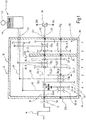
- Fig. 1 shows a motor vehicle transmission 10 in a drive train 12 shown schematically.
- a drive motor 14 is shown schematically as an internal combustion engine. It goes without saying that an electric motor, a hybrid unit or other known drive motors can also be used.
- the drive motor 14 can be connected to an input of the motor vehicle transmission 10 via a clutch arrangement 16. When the clutch arrangement 16 is closed, an input shaft 18 of the motor vehicle transmission 10 is driven by the drive motor 14. An output shaft of the motor vehicle transmission is denoted by 20.
- the input shaft 18 is arranged parallel to a countershaft 22 of the motor vehicle transmission 10 and is connected to the countershaft 22 by several gear sets, each of which has at least one idler gear 24 and one fixed gear 26.
- the countershaft 22 is connected in a rotationally fixed manner to the output shaft 20, the output shaft 20 being connected via a differential 28 or directly to the drive wheels 30R, 30L.
- the input shaft 18, the output shaft 20 and the countershaft 22 are each supported by bearing assemblies 32.
- the individual gear stages can each be inserted by means of shift clutches 36, the corresponding idler gear 24 being connected to the corresponding shaft 18, 22 in a rotationally fixed manner by the insertion of a shift clutch 36.
- the transmission has an output constant gear set 38.
- the drive power is thus transmitted from the countershaft 22 to the output shaft 20 via a gear pair consisting of two fixed gears.
- a manual H-shift device which is generally designated 40 and has a shift lever 42 which is displaceable in a shift gate 44 and can, for example, operate shift forks 46 via shift rods 48.
- the gear steps that can be shifted with the respective gear sets are in Fig. 1 and Fig. 2 indicated below the wheelsets.
- the in Fig. 1 The variant shown is the 4th gear set up as a direct corridor.
- the 5th gear is set up as a direct gear.
- the third highest gear is set up as a direct gear.
- a high spread of the transmission 10 is thereby possible.
- a direct gear is understood to mean that the input shaft 18 is non-rotatably connected to the output shaft 20 without an intermediate transmission.
- the transmission 10 has a transmission input 50 through which drive power can be introduced into the transmission 10.
- the transmission 10 further has a transmission output 52 via which drive power can be transmitted from the transmission 10 to the differential 28 or directly to the drive wheels 30R, 30L.
- the transmission 10 further has a transmission housing 54, the transmission housing 54 having a housing pot 55, a bearing plate 56 and a housing cover 58.
- the countershaft 22 is supported by a total of three bearings 32b, 32e, 32g on the transmission input 50, the bearing plate 56 and the housing cover 58.
- the output shaft 20 is supported on the housing cover 58 by the bearing 32f and is preferably additionally supported in or on the input shaft 18, which is shown in FIG Fig. 1 is not shown in detail.
- the input shaft 18 and the output shaft 20 are arranged coaxially.
- the input shaft 18 is supported by two bearings 32a, 32d, the bearing 32a being arranged on the transmission input and the bearing 32d being arranged on the bearing plate 56.
- the output shaft 20 can also be mounted on the input shaft 18.
- the output shaft 20 is supported by two bearings 32d, 32e, the bearing 32e being arranged on the transmission output 52 and the bearing 32d being arranged on the bearing plate 56.
- the bearing plate 56 is arranged in such a way that the output constant gear set 38 and a further gear set 24/26 for a gear stage are arranged between the transmission output 52 and the bearing plate 56.
- the clutches 36 can also be actuated via a rocker switch 60.
- a rocker switch 60 is mounted on a deflection device 62 in such a way that when a
- the gear stage 1 is set up by a fixed gear 64 arranged on the input shaft 18 which meshes with an idler gear 24-1 arranged on the countershaft 22.
- the fixed gear 64 is also in engagement with a direction reversing gear 66, which in turn engages with an idler gear 24 -R arranged on the countershaft 22 in order to set up the reverse gear -R.
- the gear stage 2 is also set up via a fixed gear 26-2 arranged on the input shaft 18 which meshes with an idler gear 24-2 arranged on the countershaft 22.
- the gear stages 5 and 6 are each set up by idler gears 24-5, 24-6 arranged on the input shaft, which mesh with fixed gears 26-5, 26-6 arranged on the countershaft 22.
- the gear stage 3 is set up by an idler gear 24-3 arranged on the input shaft 18, which meshes with a fixed gear 26-3 arranged on the countershaft 22.
- Individual clutches 36 can preferably be combined in so-called clutch packs 70, whereby a clutch pack 70 can be shifted in a first axial direction in order to engage a first gear stage and in a second axial direction opposite to the first one in order to engage a second gear stage .
- gear stage 4 is designed as a direct gear stage.
- the transmission arrangement can be actuated with an H shift device 40, which is shown in FIG Fig. 1 is only shown schematically.
- the switching device can be actuated in a manner known per se and has a switching lever 42 which is movably arranged in a switching gate 44.
- a shift shaft 72 can be actuated in this way by the shift lever 42 be that a shift shaft 74 couples with one of the shift rods 48, so that when the shift lever 42 moves along a shift gate, the respective shift rod 48 is displaced in the axial direction.
- the shift rod 48 moves, for example via a shift fork 46 or a shift rocker 60, a shift sleeve of a shift clutch pack 70, so that a gear step is engaged or disengaged.
- Fig. 2 For a better overview, the switching device 40, the gear housing 54, the bearing plate 56 and parts of the drive train 12 are not shown.
- Fig. 2 shows schematically a gear set layout for a 7-speed variant.
- the clutches 36-7 and 36-R for the gear stage 7 and the reverse gear stage -R are combined to form a clutch pack 70a.
- the reverse gear is as in the in Fig. 1
- the variant shown is set up via the gear set pair 64/66/24-R, with a fixed gear 64 for gear stage 1 and the reverse gear stage being arranged on the transmission input shaft 18 and engaging with an idler gear 24-R via a direction reversing gear 66.
- the idler gear 24-R is arranged on the countershaft 22 and can be connected non-rotatably to the countershaft 22 by the clutch pack 70a.
- the gear sets of gears 1 and 2 and the reverse gear-R are preferably identical to those in the 6-gear variant, as in FIG Fig. 1 shown.
- the gear stages 4 and 3 are each set up by idler gears 24-4, 24-3 arranged on the input shaft, which mesh with fixed gears 26-4, 26-3 arranged on the countershaft 22.
- the gear stage 6 is set up by an idler gear 24-6 arranged on the input shaft 18, which meshes with a fixed gear 26-6 arranged on the countershaft 22.
- the clutch packs 70a and 70b are arranged on the countershaft 22 and the clutch packs 70c and 70d on the input shaft 18.
- the clutch pack 70a shifts the 7th gear and the reverse gear.
- the clutch pack 70b shifts the 1st gear stage and the 2nd gear stage.
- the clutch pack 70c shifts the 4th and 3rd gear and can be actuated by means of a rocker switch 60-1, which is arranged on a deflection device 62-1.
- the rocker switch 60-1 is actuated by a switch rod 48.
- the clutch 70d shifts the 6th and 5th gear.
- the 5th gear is set up as a direct gear.
- the clutch pack 70d can also be actuated by means of a rocker switch 60-2 arranged on a deflection device 62-2.
- gear steps which are arranged between the 2nd gear step and the transmission output 52, are interchangeable or can be arranged in any order, namely by arranging the gear sets 24/26 and clutches 36 or clutch packs 70 accordingly.
- the bearing plate 56 and the housing cover 58 are preferably identical parts or at least can be produced from the same base part.
- the center distance between the input shaft 18 or output shaft 20 and the countershaft 22 is the same in both variants and is preferably selected so that high torque ranges and spreads are also possible for the 6-speed variant.
- Both the 6-speed variant and the 7-speed variant can be used for vehicles with a diesel engine as well as for vehicles with a gasoline engine, the torque range preferably starting at 200 Nm and being able to reach up to 800 Nm, in particular in ranges from 400 Nm to 500 Nm can be.
- first variant and the second variant are shown as a manual transmission 10, it is also conceivable to provide an automated actuation of the transmission 10 without departing from the scope of the invention.
Landscapes
- Engineering & Computer Science (AREA)
- General Engineering & Computer Science (AREA)
- Mechanical Engineering (AREA)
- Structure Of Transmissions (AREA)
- Arrangement Of Transmissions (AREA)
- Hybrid Electric Vehicles (AREA)
Description
- Die vorliegende Erfindung betrifft ein Kraftfahrzeuggetriebe für den Längseinbau in einem Kraftfahrzeug, mit einer Eingangswellenanordnung, die mit einem Ausgangsglied einer Kupplungsanordnung verbindbar ist; einer Ausgangswelle, die mit Antriebsrädern oder mit einem Differential verbindbar ist; einer Vorgelegewelle, die parallel zu der Eingangswellenanordnung angeordnet ist; einer Mehrzahl von Radsätzen zum Einrichten von Gangstufen, wobei die Radsätze jeweils an zwei der Wellen gelagert und mittels jeweiliger Schaltkupplungen schaltbar sind, die zumindest teilweise zu Schaltkupplungspaketen zusammengefasst sind; einem Gehäuse, in dem die Wellen und die Radsätze aufgenommen sind; und einer Lageranordnung zum Lagern der Wellen an dem Gehäuse, die so ausgebildet ist, dass mit dieser Lageranordnung gleichermaßen eine erste Variante und eine zweite Variante des Kraftfahrzeuggetriebes aufbaubar ist, wobei das Kraftfahrzeuggetriebe in der ersten Variante mit einer ersten Anzahl von Vorwärtsgangstufen aufbaubar ist und in der zweiten Variante mit diesen Vorwärtsgangstufen und einer weiteren Vorwärtsgangstufe aufbaubar ist.
- Derartige Kraftfahrzeuggetriebe sind beispielsweise bekannt aus der
DE 10 2005 005 338 B3 . Bei diesen bekannten Getrieben handelt es sich um sog. Inline-Getriebe, also Getriebe für den Längseinbau in einem Kraftfahrzeug. Dabei sind die Getriebe in einer ersten Variante mit sechs Gängen derart aufbaubar, dass sie mittels einer klassischen Schaltkulisse manuell schaltbar sind, also dass Schaltkupplungspakete benachbarte Gangstufen schalten. In einer weiteren Variante sind diese bekannten Getriebe mit einer weiteren Vorwärtsgangstufe als Automatikschaltgetriebe aufbaubar. - Diese bekannten Getriebe sind wenig modular und eng auf ihren Anwendungsbereich angepasst.
- Getriebe werden teilweise speziell auf Kundenanforderung entwickelt und gebaut. Dabei wird viel Arbeits- und Entwicklungsaufwand benötigt, so dass sich eine Produktion von kundenspezifischen Getrieben in Kleinserie wirtschaftlich kaum lohnt.
- Bisherige Getriebekonzepte ermöglichen nur geringfügig das Ausnutzen von Synergien. Zudem sind konventionelle Getriebe geometrisch an ihren Grenzen, um durch große Spreizung zukünftige CO2 Anforderungen zu erfüllen und die Drehmomententwicklung neuer Motorengenerationen zu berücksichtigen.
- Die
EP 1 122 463 A2 offenbart ein modulares Kraftfahrzeuggetriebe, welches unter den Wortlaut des Oberbegriffs des Anspruchs 1 fällt. - Vor dem obigen Hintergrund ist es die Aufgabe der Erfindung, ein verbessertes und wirtschaftliches Inline-Getriebe bereitzustellen, mit dem möglichst viele verschiedene Ausführungsformen, also spezielle Kundenwünsche, realisierbar sind.
- Diese Aufgabe wird durch ein modulares Kraftfahrzeuggetriebe nach Anspruch 1 gelöst. Die abhängigen Ansprüche betreffen besondere Ausführungsarten der Erfindung nach Anspruch 1.
- Durch diese Maßnahme ergibt sich eine hohe Modularität, so dass anforderungsspezifisch viele verschiedene Ausführungsformen durch das offenbarte modulare Getriebe realisiert werden können. Beide Varianten können sowohl von Hand als auch automatisiert betätigt werden.
- Die Aufgabe wird somit vollkommen gelöst.
- Von besonderem Vorteil ist es, wenn in beiden Varianten eine Direktgangstufe eingerichtet ist.
- Dadurch kann eine weitere Gangstufe ohne zusätzliches Radsatzpaar eingerichtet werden, so dass das Getriebe axial kurz baut. Zudem können Kosten und Gewicht eingespart werden.
- Durch den in Anspruch 1 genannten Abtriebs-Konstantenradsatz sind die Momentbelastungen an der Vorgelegewelle geringer als bei einem Antriebs-Konstantenradsatz, so dass die Verzahnungen der Radsätze schmaler ausgeführt werden können. Dadurch kann das Getriebe generell in axialer Richtung kürzer ausgebildet sein. Zudem sind die Belastungen der Schaltkupplungen geringer, wodurch kürzere Schaltzeiten realisiert werden können.
- Mit der Erfindung ergibt sich eine Lagerung der Abtriebswelle mit einem günstigen Tragbild, wobei eine sehr steife Lagerung des Abtriebs-Konstantenradsatzes erreicht wird. Zudem ergibt sich in der Regel eine günstige Lagerbelastung.
- Eine weitere bevorzugte Ausführungsform sieht vor, dass der Getriebedeckel des Gehäuses und/oder die Lagerplatte in beiden Varianten aus identischen Teilen gefertigt werden können und bevorzugt identisch sind.
- Durch diese Maßnahme lassen sich weitere Synergien generieren, so dass auch Getriebe in Kleinserie noch wirtschaftlicher realisierbar sind. Durch die Verwendung von Gleichteilen können diese Gleichteile in größeren Stückzahlen produziert werden, was die Produktionskosten weiter senkt. Des Weiteren reduziert die Verwendung von Gleichteilen den Lageraufwand im Ersatzteillager sowie den Verwaltungsaufwand der Lagerbestände, was die Kosten weiter senken und die Wirtschaftlichkeit weiter verbessern kann.
- Von besonderem Vorteil ist es dabei, wenn in der ersten Variante ein Rückwärtsgangstufen-Radsatz der einem Eingang des Kraftfahrzeuggetriebes nächste Radsatz ist und mittels einer Rückwärtsgangstufen-Schaltkupplung betätigbar ist, die auf der dem Getriebeeingang zugewandten Seite des Rückwärtsgangstufen-Radsatzes angeordnet ist, wobei in der zweiten Variante ein Radsatz für die weitere Vorwärtsgangstufe auf der dem Getriebeeingang zugewandten Seite einer Rückwärtsgangstufen-Schaltkupplung angeordnet ist, wobei die Rückwärtsgangstufen-Schaltkupplung mit einer weiteren Schaltkupplung für die weitere Gangstufe in ein Schaltkupplungspaket integriert ist.
- Durch diese Maßnahme baut auch die zweite Variante des Inline-Getriebes axial kurz. Zudem kann die zusätzliche Vorwärtsgangstufe der zweiten Variante konstruktiv günstig realisiert werden.
- Gemäß einer bevorzugten Ausführungsform sind in der ersten Variante folgende Bauelemente axial hintereinander angeordnet, von einem Getriebeeingang aus gesehen: eine Rückwärtsgangstufen-Schaltkupplung, ein Rückwärtsgangstufen-Radsatz, ein Radsatz für Gangstufe 1, ein Schaltkupplungspaket für Gangstufen 1 und 2, ein Radsatz für Gangstufe 2, ein Radsatz für Gangstufe 5, ein Schaltkupplungspaket für Gangstufen 5 und 6, ein Radsatz für Gangstufe 6, ein Radsatz für Gangstufe 3, ein Schaltkupplungspaket für Gangstufen 3 und 4, und ein Abtriebs-Konstantenradsatz.
- Durch diese vorteilhafte Fahrzeuggetriebeanordnung ist es möglich das Kraftfahrzeuggetriebe mit einer H-Schaltkulisse zu schalten, wobei Schaltstangen direkt mit Schaltgabeln verbindbar sind, wobei keine Umlenkung/Richtungsumkehr der Betätigungsrichtung einer Schaltkupplung realisiert werden muss. Das Getriebe kann demnach mechanisch einfach geschaltet werden.
- Gemäß einer weiteren bevorzugten Ausführungsform sind in der zweiten Variante folgende Bauelemente axial hintereinander angeordnet, von einem Getriebeeingang aus gesehen: ein Radsatz für Gangstufe 7, ein Schaltkupplungspaket für Gangstufe 7 und die Rückwärtsgangstufe R, ein Rückwärtsgangstufen-Radsatz, ein Radsatz für Gangstufe 1, ein Schaltkupplungspaket für Gangstufen 1 und 2, ein Radsatz für Gangstufe 2, ein Radsatz für Gangstufe 4, ein Schaltkupplungspaket für Gangstufen 4 und 3, ein Radsatz für Gangstufe 3, ein Radsatz für Gangstufe 6, ein Schaltkupplungspaket für die Gangstufen 6 und 5, und ein Abtriebs-Konstantenradsatz.
- Durch dieses vorteilhafte Radsatzlayout ist es möglich das Getriebe auch in der zweiten Variante, also mit 7 Gangstufen, derart aufzubauen, dass es manuell mittels einer H-Schaltkulisse schaltbar ist, da die Schaltkupplungspakete jeweils benachbarte Gangstufen schalten.
- Von besonderem Vorzug ist es, wenn wenigstens ein Schaltkupplungspaket mittels einer Schaltgabel betätigbar ist und/oder wenigstens ein Schaltkupplungspaket mittels Schaltwippe betätigtbar ist. Die Betätigung kann jeweils mittels einer Schaltstange erfolgen oder beispielsweise mittels einer Seilzugschaltung und Mitnehmervorrichtung bzw. Koppelstück.
- Eine Schaltwippe ist dabei an einer um eine quer zur Schaltstange ausgerichtete Umlenkachse (Umlenkvorrichtung) derart gelagert, dass bei einer Betätigung (beispielsweise mittels einer Schaltstange) in eine erste axiale Richtung durch die Umlenkvorrichtung das der Schaltwippe zugeordnete Schaltkupplungspaket in einer zu der ersten Richtung entgegengesetzten axialen Richtung verschoben wird. In der zweiten Variante ist es bevorzugt, wenn das Schaltkupplungspaket für die Gangstufen 1/2 mittels einer Schaltgabel geschaltet wird und die Schaltkupplungspakete für die Gangstufen 4/3 und 6/5 mittels jeweiliger Schaltwippen schaltbar sind.
- Vorteilhaft dabei ist, dass auch das Radsatzlayout der zweiten Variante konstruktiv einfach manuell schaltbar ausgeführt sein kann.
- Von besonderem Vorzug ist es, wenn der/ein Radsatz für die Gangstufe 1, der/ein Rückwärtsgangradsatz und vorzugsweise der/ein Radsatz für die Gangstufe 2 in beiden Varianten durch Gleichteile gebildet sind.
- Dadurch können weitere Synergien generiert werden, wodurch die Wirtschaftlichkeit der Kraftfahrzeuggetriebe weiter verbessert werden kann.
- Ausführungsbeispiele der Erfindung sind in den Zeichnungen dargestellt und werden in der nachfolgenden Beschreibung näher erläutert. Es zeigen:
-
Fig. 1 eine schematische Darstellung einer Ausführungsform des erfindungsgemäßen Kraftfahrzeuggetriebes in einer ersten Variante, wobei der Radsatzaufbau für ein 6-Gang-Handschaltgetriebe geeignet ist; und -
Fig. 2 eine schematische Darstellung einer weiteren Ausführungsform des erfindungsgemäßen Kraftfahrzeuggetriebes in einer zweiten Variante, wobei der Radsatzaufbau für ein 7-Gang-Handschaltgetriebe geeignet ist. -
Fig. 1 zeigt ein Kraftfahrzeuggetriebe 10 in einem schematisch dargestellten Antriebsstrang 12. Dabei ist ein Antriebsmotor 14 schematisch als Brennkraftmaschine dargestellt. Es versteht sich, dass auch ein Elektromotor, eine Hybrideinheit oder andere bekannte Antriebsmotoren verwendet werden können. - Der Antriebsmotor 14 ist über eine Kupplungsanordnung 16 mit einem Eingang des Kraftfahrzeuggetriebes 10 verbindbar. Bei geschlossener Kupplungsanordnung 16 wird eine Eingangswelle 18 des Kraftfahrzeuggetriebes 10 durch den Antriebsmotor 14 angetrieben. Eine Ausgangswelle des Kraftfahrzeuggetriebes ist mit 20 bezeichnet.
- Die Eingangswelle 18 ist parallel zu einer Vorgelegewelle 22 des Kraftfahrzeuggetriebes 10 angeordnet und ist durch mehrere Radsätze mit der Vorgelegewelle 22 verbunden, die jeweils zumindest ein Losrad 24 und ein Festrad 26 aufweisen.
- Die Vorgelegewelle 22 ist drehfest mit der Ausgangswelle 20 verbunden, wobei die Ausgangswelle 20 über ein Differential 28 oder direkt mit den Antriebsrädern 30R, 30L verbunden ist.
- Die Eingangswelle 18, die Ausgangswelle 20 und die Vorgelegewelle 22 sind jeweils durch Lageranordnungen 32 gelagert.
- Die einzelnen Gangstufen sind jeweils durch Schaltkupplungen 36 einlegbar, wobei durch das Einlegen einer Schaltkupplung 36 das entsprechende Losrad 24 drehfest mit der entsprechenden Welle 18, 22 verbunden wird.
- Das Getriebe weist einen Abtriebs-Konstantenradsatz 38 auf. Die Antriebsleistung wird also über ein Zahnradpaar bestehend aus zwei Festrädern von der Vorgelegewelle 22 auf die Ausgangswelle 20 übertragen.
- Das in
Fig. 1 gezeigte Getriebe ist mit einer manuellen H-Schaltvorrichtung betätigbar, die allgemein mit 40 bezeichnet ist und einen Schalthebel 42 aufweist, der in einer Schaltkulisse 44 verschiebbar ist und z.B. Schaltgabeln 46 über Schaltstangen 48 betätigen kann. - Die mit den jeweiligen Radsätzen schaltbaren Gangstufen sind in
Fig. 1 undFig. 2 jeweils unterhalb der Radsätze angegeben. In der inFig. 1 gezeigten Variante ist die 4. Gangstufe als Direktgang eingerichtet. In einer inFig. 2 gezeigten Variante ist die 5. Gangstufe als Direktgang eingerichtet. Es ist also jeweils die dritthöchste Gangstufe als Direktgang eingerichtet. Dadurch ist eine hohe Spreizung des Getriebes 10 möglich. Unter einem Direktgang wird verstanden, dass die Eingangswelle 18 ohne Zwischenübersetzung mit der Ausgangswelle 20 drehfest verbunden ist. - Das Getriebe 10 weist einen Getriebeeingang 50 auf, durch den Antriebsleistung in das Getriebe 10 eingebracht werden kann. Das Getriebe 10 weist weiter einen Getriebeausgang 52 auf, über den Antriebsleistung vom Getriebe 10 auf das Differential 28 oder direkt auf die Antriebsräder 30R, 30L übertragen werden kann.
- Das Getriebe 10 weist weiter ein Getriebegehäuse 54 auf, wobei das Getriebegehäuse 54 einen Gehäusetopf 55, eine Lagerplatte 56 und einen Gehäusedeckel 58 aufweist.
- Die Vorgelegewelle 22 ist mit insgesamt drei Lagern 32b, 32e, 32g an dem Getriebeeingang 50, der Lagerplatte 56 und dem Gehäusedeckel 58 gelagert. Die Ausgangswelle 20 ist am Gehäusedeckel 58 durch das Lager 32f gelagert und ist vorzugsweise zusätzlich in oder an der Eingangswelle 18 gelagert, was in
Fig. 1 nicht näher dargestellt ist. Die Eingangswelle 18 und die Ausgangswelle 20 sind dabei koaxial angeordnet. - In dem Fall, dass die Ausgangswelle 20 in der Eingangswelle 18 gelagert ist, ist die Eingangswelle 18 mit zwei Lagern 32a, 32d gelagert, wobei das Lager 32a am Getriebeeingang angeordnet ist und das Lager 32d an der Lagerplatte 56 angeordnet ist.
- Die Ausgangswelle 20 kann auch an der Eingangswelle 18 gelagert sein. In diesem Fall ist die Ausgangswelle 20 mit zwei Lagern 32d, 32e gelagert, wobei das Lager 32e am Getriebeausgang 52 angeordnet ist und das Lager 32d an der Lagerplatte 56 angeordnet ist.
- Die Lagerplatte 56 ist dabei so angeordnet, dass zwischen Getriebeausgang 52 und Lagerplatte 56 der Abtriebs-Konstantenradsatz 38 und ein weiterer Radsatz 24/26 für eine Gangstufe angeordnet sind.
- Die Schaltkupplungen 36 können auch über eine Schaltwippe 60 betätigt werden. Eine Schaltwippe 60 ist dabei derart an einer Umlenkvorrichtung 62 gelagert, dass bei einer
- Betätigung einer Schaltstange 48 in einer ersten axialen Richtung durch die Umlenkvorrichtung 62, die der Schaltwippe 60 zugeordnete Schaltkupplung 36 in einer zu der ersten Richtung entgegengesetzten axialen Richtung verschoben wird.
- In der in
Fig. 1 gezeigten 6-Gang Variante ist die Gangstufe 1 durch ein an der Eingangswelle 18 angeordnetes Festrad 64 eingerichtet, das mit einem an der Vorgelegewelle 22 angeordneten Losrad 24-1 im Eingriff steht. Das Festrad 64 steht dabei zudem im Eingriff mit einem Richtungsumkehrrad 66, das wiederum mit einem an der Vorgelegewelle 22 angeordnetem Losrad 24-R in Eingriff steht, um so die Rückwärtsgangstufe-R einzurichten. Die Gangstufe 2 ist ebenfalls über ein an der Eingangswelle 18 angeordnetes Festrad 26-2 eingerichtet, das mit einem an der Vorgelegewelle 22 angeordneten Losrad 24-2 in Eingriff steht. Die Gangstufen 5 und 6 sind jeweils eingerichtet durch an der Eingangswelle angeordnete Losräder 24-5, 24-6 die mit an der Vorgelegewelle 22 angeordneten Festrädern 26-5, 26-6 in Eingriff stehen. Die Gangstufe 3 ist eingerichtet durch ein an der Eingangswelle 18 angeordnetes Losrad 24-3, das mit einem an der Vorgelegewelle 22 angeordnetem Festrad 26-3 im Eingriff steht. - Einzelne Schaltkupplungen 36 können vorzugsweise in so genannten Schaltkupplungspaketen 70 zusammengefasst sein, wobei ein Schaltkupplungspaket 70 in einer ersten axialen Richtung verschoben werden kann um eine erste Gangstufe einzulegen und in einer zweiten, zu der ersten entgegengesetzten, axialen Richtung verschoben werden kann um eine zweite Gangstufe einzulegen.
- In der in
Fig. 1 gezeigten Variante sind die einzelnen Vorwärtsgangstufen mittels Schaltkupplungspaketen 70b, 70c, 70d schaltbar. Die Gangstufen 1 und 2 sind dabei vom Schaltkupplungspaket 70b schaltbar, die Gangstufen 3 und 4 vom Schaltkupplungspaket 70d und die Gangstufen 5 und 6 vom Schaltkupplungspaket 70c. Die Rückwärtsgangstufe-R ist mittels einer Schaltkupplung 36-R schaltbar. In dieser Variante ist die Gangstufe 4 als Direktgangstufe ausgebildet. - Die Getriebeanordnung ist mit einer H-Schaltvorrichtung 40 betätigbar, die in
Fig. 1 nur schematisch dargestellt ist. Die Schaltvorrichtung kann in an sich bekannter Weise betätigt werden und weist einen Schalthebel 42 auf, der in einer Schaltkulisse 44 beweglich angeordnet ist. Durch den Schalthebel 42 kann eine Schaltwelle 72 derart betätigt werden, dass eine Schaltwelle 74 mit einer der Schaltstangen 48 koppelt, so dass bei einer Bewegung des Schalthebels 42 entlang einer Schaltgasse die jeweilige Schaltstange 48 in axialer Richtung verschoben wird. Hierdurch verschiebt die Schaltstange 48 beispielsweise über eine Schaltgabel 46 oder eine Schaltwippe 60, eine Schaltmuffe eines Schaltkupplungspaketes 70, so dass eine Gangstufe eingelegt oder ausgelegt wird. - In
Fig. 2 sind zur besseren Übersicht die Schaltvorrichtung 40, das Getriebegehäuse 54, die Lagerplatte 56 sowie Teile des Antriebsstranges 12 nicht dargestellt. -
Fig. 2 zeigt schematisch ein Radsatzlayout für eine 7-Gang-Variante. Dabei sind die Schaltkupplungen 36-7 und 36-R für die Gangstufe 7 und die Rückwärtsgangstufe-R zu einem Schaltkupplungspaket 70a zusammengefasst. Die Rückwärtsgangstufe ist, wie in der inFig. 1 gezeigten Variante, über das Radsatzpaar 64/66/24-R eingerichtet, wobei ein Festrad 64 für die Gangstufe 1 und die Rückwärtsgangstufe an der Getriebeeingangswelle 18 angeordnet ist und über ein Richtungsumkehrrad 66 mit einem Losrad 24-R in Eingriff steht. Das Losrad 24-R ist an der Vorgelegewelle 22 angeordnet und mit dem Schaltkupplungspaket 70a mit der Vorgelegewelle 22 drehfest verbindbar. - Die Radsätze der Gangstufen 1 und 2 und der Rückwärtsgangstufe-R sind vorzugsweise identisch zu denen in der 6-Gang-Variante, wie in der
Fig. 1 gezeigt. - Die Gangstufen 4 und 3 sind jeweils eingerichtet durch an der Eingangswelle angeordnete Losräder 24-4, 24-3 die mit an der Vorgelegewelle 22 angeordneten Festrädern 26-4, 26-3 im Eingriff stehen. Die Gangstufe 6 ist eingerichtet durch ein an der Eingangswelle 18 angeordnetes Losrad 24-6, das mit einem an der Vorgelegewelle 22 angeordnetem Festrad 26-6 im Eingriff steht.
- In dem in
Fig. 2 gezeigten Radsatzlayout sind die Schaltkupplungspakete 70a und 70b an der Vorgelegewelle 22 angeordnet und die Schaltkupplungspakete 70c und 70d an der Eingangswelle 18. Das Schaltkupplungspaket 70a schaltet dabei die 7. Gangstufe sowie die Rückwärtsgangstufe. Das Schaltkupplungspaket 70b schaltet die 1. Gangstufe und die 2. Gangstufe. Das Schaltkupplungspaket 70c schaltet die 4. und die 3. Gangstufe und ist betätigbar mittels einer Schaltwippe 60-1, die an einer Umlenkvorrichtung 62-1 angeordnet ist. Die Schaltwippe 60-1 wird dabei durch eine Schaltstange 48 betätigt. Die Schaltkupplung 70d schaltet die 6. und die 5. Gangstufe. Die 5. Gangstufe ist als Direktgangstufe eingerichtet. Auch das Schaltkupplungspaket 70d ist mittels einer an einer Umlenkvorrichtung 62-2 angeordneten Schaltwippe 60-2 betätigbar. - In beiden Radsatzlayouts verläuft der Drehmomentfluss dabei, mit Ausnahme der Direktgangstufen, immer von der Getriebeeingangswelle 18 über die Vorgelegewelle 22 mittels des Abtriebs-Konstantenradsatzes 38 an die Getriebeausgangswelle 20.
- In beiden Varianten sind die Gangstufen, die zwischen der 2ten Gangstufe und dem Getriebeausgang 52 angeordnet sind, austauschbar bzw. in beliebiger Reihenfolge anordenbar, und zwar durch entsprechendes Anordnen der Radsätze 24/26 und Schaltkupplungen 36 bzw. Schaltkupplungspakete 70.
- Die Lagerplatte 56 und der Gehäusedeckel 58 sind vorzugsweise Gleichteile oder wenigstens aus dem gleichen Basisteil herstellbar.
- Der Achsabstand zwischen der Eingangswelle 18 bzw. Ausgangswelle 20 und der Vorgelegewelle 22 ist bei beiden Varianten gleich und vorzugsweise so gewählt, dass auch für die 6-Gang-Variante hohe Drehmomentbereiche und Spreizungen möglich sind.
- Sowohl die 6-Gang-Variante als auch die 7-Gang-Variante sind dabei sowohl für Fahrzeuge mit Dieselmotor als auch für Fahrzeuge mit Ottomotor verwendbar, wobei der Drehmoment Bereich vorzugsweise bei 200 Nm beginnt und bis 800 Nm reichen kann, insbesondere in Bereichen von 400 Nm bis 500 Nm liegen kann.
- Obwohl die erste Variante und die zweite Variante als manuelle Getriebe 10 dargestellt sind, ist es auch denkbar, eine automatisierte Aktuierung der Getriebe 10 vorzusehen, ohne den Rahmen der Erfindung zu verlassen.
Claims (8)
- Modulares Kraftfahrzeuggetriebe (10) für den Längseinbau in einem Kraftfahrzeug, mit- einer Eingangswellenanordnung (18), die mit einem Ausgangsglied (68) einer Kupplungsanordnung (16) verbindbar ist,- einer Ausgangswelle (20), die mit Antriebsrädern (30R, 30L) oder mit einem Differential (28) verbindbar ist,- einer Vorgelegewelle (22), die parallel zu der Eingangswellenanordnung (18) angeordnet ist,- einer Mehrzahl von Radsätzen (24/26, 24/64/66, 64/24) zum Einrichten von Gangstufen (R; 1; 2; 3; 4; 5; 6; 7), wobei die Radsätze (24/26, 24/64/66, 64/24) jeweils an der Eingangswellenanordnung (18) und der Vorgelegewelle (22) gelagert sind und diese miteinander verbinden und wobei die Radsätze (24/26, 24/64/66, 64/24) jeweils ein Festrad (26, 26-2, 26-3, 26-4, 26-5, 26-6, 64) und ein Losrad (24, 24-1, 24-2, 24-3, 24-4, 24-5, 24-6, 24-R) aufweisen und mittels jeweiliger Schaltkupplungen (36, 36-7, 36-R) zum Einrichten der Gangstufen (R, 1, 2, 3, 4, 5, 6, 7) schaltbar sind, wobei die Schaltkupplungen zumindest teilweise zu Schaltkupplungspaketen (70) zusammengefasst sind,- einem Gehäuse (54), in dem die Wellen (18, 20, 22) und die Radsätze (24/26, 24/64/66, 64/24) aufgenommen sind, und- einer Lageranordnung (32a, 32b, 32c, 32d, 32e, 32f, 32g) zum Lagern der Wellen (18, 20, 22) an dem Gehäuse (54), die so ausgebildet ist, dass mit dieser Lageranordnung (32a, 32b, 32c, 32d, 32e, 32f, 32g) gleichermaßen eine erste Variante und eine zweite Variante des Kraftfahrzeuggetriebes (10) aufbaubar ist, wobei das Kraftfahrzeuggetriebe (10) in der ersten Variante mit einer ersten Anzahl von Vorwärtsgangstufen (1; 2; 3; 4; 5; 6) aufgebaut ist und in der zweiten Variante mit einer weiteren Vorwärtsgangstufe (7) aufgebaut ist, dadurch gekennzeichnet, dass die Radsätze (24/26, 24/64/66, 64/24) und zugeordneten Schaltkupplungen und Schaltkupplungspakete (70, 70a, 70b, 70c, 70d) in beiden Varianten so gewählt sind, dass eine manuelle Schaltung möglich ist, so dass das Kraftfahrzeuggetriebe (10) in beiden Varianten als manuelles Getriebe mit einer H-Schaltvorrichtung (40) realisierbar ist, das nicht automatisch aktuiert ist, wobei die H-Schaltvorrichtung (40) einen Schalthebel (42) aufweist, der in einer Schaltkulisse (44) verschiebbar ist, wobei die Vorgelegewelle (22) und die Ausgangswelle (20) über einen Abtriebs-Konstantenradsatz (38) miteinander verbunden sind,
wobei ausschließlich der Abtriebs-Konstantenradsatz (38) und genau ein weiterer Radsatz (24/26), in axialer Richtung gesehen, in beiden Varianten zwischen einem getriebeausgangsseitigen Getriebedeckel (58) und einer Lagerplatte (56) angeordnet sind. - Modulares Kraftfahrzeuggetriebe (10) nach Anspruch 1, dadurch gekennzeichnet, dass in beiden Varianten eine Direktgangstufe (4, 5) eingerichtet ist.
- Modulares Kraftfahrzeuggetriebe (10) nach Anspruch 1 oder 2, dadurch gekennzeichnet, dass der Getriebedeckel (58) des Gehäuses (54) und/oder die Lagerplatte (56) in beiden Varianten identisch sind.
- Modulares Kraftfahrzeuggetriebe (10) nach Anspruch 1, 2 oder 3, dadurch gekennzeichnet, dass in der ersten Variante ein Rückwärtsgangstufen-Radsatz (24-R/64/ 66) der einem Eingang (50) des Kraftfahrzeuggetriebes (10) nächste Radsatz (24-R/64/66) ist und mittels einer Rückwärtsgangstufen-Schaltkupplung (36-R) betätigbar ist, die auf der dem Getriebeeingang (50) zugewandten Seite des Rückwärtsgangstufen-Radsatzes (24-R/64/66) angeordnet ist, wobei in der zweiten Variante ein Radsatz (24-7/26-7) für die weitere Vorwärtsgangstufe (7) auf der dem Getriebeeingang (50) zugewandten Seite einer Rückwärtsgangstufen-Schaltkupplung (36-R) angeordnet ist, wobei die Rückwärtsgangstufen-Schaltkupplung (36-R) mit einer weiteren Schaltkupplung (36-7) für die weitere Gangstufe (7) in ein Schaltkupplungspaket (70a) integriert ist.
- Modulares Kraftfahrzeuggetriebe (10) nach einem der Ansprüche 1 bis 4, dadurch gekennzeichnet, dass in der ersten Variante folgende Bauelemente axial hintereinander angeordnet sind, von einem Getriebeeingang (50) aus gesehen: eine Rückwärtsgangstufen-Schaltkupplung (36-R), ein Rückwärtsgangstufen-Radsatz (24-R/64/66), ein Radsatz (24-1/64) für Gangstufe 1, ein Schaltkupplungspaket (70b) für Gangstufen 1 und 2, ein Radsatz (24-2/26-2) für Gangstufe 2, ein Radsatz (24-5/26-5) für Gangstufe 5, ein Schaltkupplungspaket (70c) für Gangstufen 5 und 6, ein Radsatz (24-6/26-6) für Gangstufe 6, ein Radsatz (24-3/26-3) für Gangstufe 3, ein Schaltkupplungspaket (70d) für Gangstufen 3 und 4, und der Abtriebs-Konstantenradsatz (38).
- Modulares Kraftfahrzeuggetriebe (10) nach einem der Ansprüche 1 bis 5, dadurch gekennzeichnet, dass in der zweiten Variante folgende Bauelemente axial hintereinander angeordnet sind, von einem Getriebeeingang aus gesehen: ein Radsatz (24-7/26-7) für Gangstufe 7, ein Schaltkupplungspaket (70a) für Gangstufen 7 und die Rückwärtsgangstufe R, ein Rückwärtsgangstufen-Radsatz (24-R/64/66), ein Radsatz (24-1/64) für Gangstufe 1, ein Schaltkupplungspaket (70b) für Gangstufen 1 und 2, ein Radsatz (24-2/26-2) für Gangstufe 2, ein Radsatz (24-4/26-4) für Gangstufe 4, ein Schaltkupplungspaket (70c) für Gangstufen 4 und 3, ein Radsatz (24-3/26-3) für Gangstufe 3, ein Radsatz (24-6/26-6) für Gangstufe 6, ein Schaltkupplungspaket (70d) für Gangstufen 6 und 5, und der Abtriebs-Konstantenradsatz (38).
- Modulares Kraftfahrzeuggetriebe (10) nach einem der Ansprüche 1 bis 6, dadurch gekennzeichnet, dass wenigstens ein Schaltkupplungspaket (70) mittels einer Schaltgabel (46) betätigbar ist und/oder wenigstens ein Schaltkupplungspaket (70) mittels einer Schaltwippe (60) betätigbar ist.
- Modulares Kraftfahrzeuggetriebe (10) nach einem der Ansprüche 1 bis 7, dadurch gekennzeichnet, dass ein Radsatz (24-1/64) für die Gangstufe 1, ein Rückwärtsgangradsatz (24-R/64/66) und vorzugsweise ein Radsatz (24-2/26-2) für die Gangstufe 2 in beiden Varianten durch Gleichteile gebildet sind.
Applications Claiming Priority (2)
| Application Number | Priority Date | Filing Date | Title |
|---|---|---|---|
| DE102016100475.8A DE102016100475A1 (de) | 2016-01-13 | 2016-01-13 | Kraftfahrzeuggetriebe für den Längseinbau in einem Kraftfahrzeug |
| PCT/EP2017/050105 WO2017121664A1 (de) | 2016-01-13 | 2017-01-04 | Kraftfahrzeuggetriebe für den längseinbau in einem kraftfahrzeug |
Publications (2)
| Publication Number | Publication Date |
|---|---|
| EP3403003A1 EP3403003A1 (de) | 2018-11-21 |
| EP3403003B1 true EP3403003B1 (de) | 2020-09-02 |
Family
ID=57749961
Family Applications (1)
| Application Number | Title | Priority Date | Filing Date |
|---|---|---|---|
| EP17700046.0A Active EP3403003B1 (de) | 2016-01-13 | 2017-01-04 | Kraftfahrzeuggetriebe für den längseinbau in einem kraftfahrzeug |
Country Status (4)
| Country | Link |
|---|---|
| EP (1) | EP3403003B1 (de) |
| CN (1) | CN108474456B (de) |
| DE (1) | DE102016100475A1 (de) |
| WO (1) | WO2017121664A1 (de) |
Families Citing this family (1)
| Publication number | Priority date | Publication date | Assignee | Title |
|---|---|---|---|---|
| CN108953537A (zh) * | 2018-08-03 | 2018-12-07 | 东南大学 | 一种模块化级联式变速器 |
Family Cites Families (11)
| Publication number | Priority date | Publication date | Assignee | Title |
|---|---|---|---|---|
| DE19959616A1 (de) * | 1999-12-10 | 2001-06-13 | Volkswagen Ag | Steuereinrichtung für ein automatisch und manuell schaltbares Schaltgetriebe in einem Kraftfahrzeug |
| GB2358680A (en) * | 2000-01-31 | 2001-08-01 | Eaton Corp | A transmission with low inertia shaft |
| JP4517694B2 (ja) * | 2004-03-22 | 2010-08-04 | 日産自動車株式会社 | ツインクラッチ式マニュアルトランスミッション |
| DE102005005338B3 (de) | 2005-01-27 | 2006-08-10 | Getrag Getriebe- Und Zahnradfabrik Hermann Hagenmeyer Gmbh & Cie Kg | Stufenwechselgetriebe |
| CN201487172U (zh) * | 2009-08-06 | 2010-05-26 | 浙江长泰机械有限公司 | 带主、副箱的中型汽车变速器 |
| CN102162504A (zh) * | 2010-07-12 | 2011-08-24 | 石铭正 | 电动车圆柱体变速箱 |
| DE102010055735A1 (de) * | 2010-12-22 | 2012-06-28 | Getrag Ford Transmissions Gmbh | Verfahren zur Modifizierung eines Schaltgetriebes |
| CN202032059U (zh) * | 2011-02-22 | 2011-11-09 | 长城汽车股份有限公司 | 横置五挡全同步机械变速器 |
| CN102230520A (zh) * | 2011-07-21 | 2011-11-02 | 安徽江淮汽车股份有限公司 | 手动换挡变速器的传动装置 |
| DE102012212910B4 (de) * | 2012-07-24 | 2020-02-06 | Bayerische Motoren Werke Aktiengesellschaft | Schalteinrichtung zum Schalten eines Getriebes |
| DE102014008044A1 (de) * | 2014-05-28 | 2015-12-03 | GM Global Technology Operations LLC (n. d. Ges. d. Staates Delaware) | Verfahren und Vorrichtung zum Unterstützen eines Fahrers eines Kraftfahrzeugs |
-
2016
- 2016-01-13 DE DE102016100475.8A patent/DE102016100475A1/de not_active Withdrawn
-
2017
- 2017-01-04 WO PCT/EP2017/050105 patent/WO2017121664A1/de not_active Ceased
- 2017-01-04 EP EP17700046.0A patent/EP3403003B1/de active Active
- 2017-01-04 CN CN201780006596.8A patent/CN108474456B/zh active Active
Also Published As
| Publication number | Publication date |
|---|---|
| DE102016100475A1 (de) | 2017-07-13 |
| CN108474456A (zh) | 2018-08-31 |
| CN108474456B (zh) | 2021-03-12 |
| WO2017121664A1 (de) | 2017-07-20 |
| EP3403003A1 (de) | 2018-11-21 |
Similar Documents
| Publication | Publication Date | Title |
|---|---|---|
| DE102004022413B4 (de) | Doppelkupplungsgetriebe | |
| EP2558745B1 (de) | Doppelkupplungs-gruppengetriebe und verfahren zur betätigung eines doppelkupplungs-gruppengetriebes | |
| EP2111514B1 (de) | Doppelkupplungsgetriebe eines kraftfahrzeugs | |
| EP1616116B1 (de) | Mehrstufiges schaltgetriebe für eine brennkraftmaschine | |
| EP1846669A1 (de) | Doppelkupplungsgetriebe | |
| DE102011076382A1 (de) | Doppelkupplungsgetriebe | |
| EP3259500B1 (de) | Doppelkupplungsgetriebe für ein kraftfahrzeug | |
| DE4116189C2 (de) | Schaltgetriebe | |
| DE112006002161T5 (de) | Doppelvorgelege-Getriebe | |
| EP3180548B1 (de) | Geschwindigkeits-wechselgetriebe für ein kraftfahrzeug | |
| EP1740848A1 (de) | Schaltgetriebe in vorgelegewellenbauweise | |
| DE102011076381B4 (de) | Doppelkupplungsgetriebe | |
| EP2469125B1 (de) | Automatisches, insbesondere automatisiertes Schaltgetriebe für ein Kraftfahrzeug | |
| EP1455116B1 (de) | Kurzbauendes Zahnradwechselgetriebe | |
| DE102009018450B4 (de) | Doppelkupplungsgetriebe | |
| DE4422901A1 (de) | Vielgängiges Stufenwechselgetriebe | |
| DE102009050151A1 (de) | Schaltvorrichtung zur Schaltung eines Doppelkupplungsgetriebes | |
| EP3403003B1 (de) | Kraftfahrzeuggetriebe für den längseinbau in einem kraftfahrzeug | |
| DE2822617C2 (de) | ||
| EP0595059B1 (de) | Gangschaltgetriebe eines Kraftfahrzeuges | |
| EP1004795B1 (de) | Wechselgetriebe mit einer Vorgelegewelle, insbesondere für Kraftfahrzeuge | |
| DE102013005659A1 (de) | Schaltgetriebe für Kraftfahrzeuge | |
| DE10232835B4 (de) | Doppelkupplungsgetriebe | |
| EP1130291B1 (de) | Getriebekonzept für ein 6-Gang-Vorgelege-Wechselgetriebe für Kraftfahrzeuge | |
| DE102013005644A1 (de) | Schaltgetriebe für Kraftfahrzeuge |
Legal Events
| Date | Code | Title | Description |
|---|---|---|---|
| STAA | Information on the status of an ep patent application or granted ep patent |
Free format text: STATUS: UNKNOWN |
|
| STAA | Information on the status of an ep patent application or granted ep patent |
Free format text: STATUS: THE INTERNATIONAL PUBLICATION HAS BEEN MADE |
|
| PUAI | Public reference made under article 153(3) epc to a published international application that has entered the european phase |
Free format text: ORIGINAL CODE: 0009012 |
|
| STAA | Information on the status of an ep patent application or granted ep patent |
Free format text: STATUS: REQUEST FOR EXAMINATION WAS MADE |
|
| 17P | Request for examination filed |
Effective date: 20180718 |
|
| AK | Designated contracting states |
Kind code of ref document: A1 Designated state(s): AL AT BE BG CH CY CZ DE DK EE ES FI FR GB GR HR HU IE IS IT LI LT LU LV MC MK MT NL NO PL PT RO RS SE SI SK SM TR |
|
| AX | Request for extension of the european patent |
Extension state: BA ME |
|
| DAV | Request for validation of the european patent (deleted) | ||
| DAX | Request for extension of the european patent (deleted) | ||
| RAP1 | Party data changed (applicant data changed or rights of an application transferred) |
Owner name: MAGNA PT B.V. & CO. KG |
|
| GRAP | Despatch of communication of intention to grant a patent |
Free format text: ORIGINAL CODE: EPIDOSNIGR1 |
|
| STAA | Information on the status of an ep patent application or granted ep patent |
Free format text: STATUS: GRANT OF PATENT IS INTENDED |
|
| INTG | Intention to grant announced |
Effective date: 20200515 |
|
| GRAS | Grant fee paid |
Free format text: ORIGINAL CODE: EPIDOSNIGR3 |
|
| GRAA | (expected) grant |
Free format text: ORIGINAL CODE: 0009210 |
|
| STAA | Information on the status of an ep patent application or granted ep patent |
Free format text: STATUS: THE PATENT HAS BEEN GRANTED |
|
| AK | Designated contracting states |
Kind code of ref document: B1 Designated state(s): AL AT BE BG CH CY CZ DE DK EE ES FI FR GB GR HR HU IE IS IT LI LT LU LV MC MK MT NL NO PL PT RO RS SE SI SK SM TR |
|
| REG | Reference to a national code |
Ref country code: GB Ref legal event code: FG4D Free format text: NOT ENGLISH |
|
| REG | Reference to a national code |
Ref country code: AT Ref legal event code: REF Ref document number: 1309181 Country of ref document: AT Kind code of ref document: T Effective date: 20200915 Ref country code: CH Ref legal event code: EP |
|
| REG | Reference to a national code |
Ref country code: DE Ref legal event code: R096 Ref document number: 502017007034 Country of ref document: DE |
|
| REG | Reference to a national code |
Ref country code: IE Ref legal event code: FG4D Free format text: LANGUAGE OF EP DOCUMENT: GERMAN |
|
| REG | Reference to a national code |
Ref country code: LT Ref legal event code: MG4D |
|
| PG25 | Lapsed in a contracting state [announced via postgrant information from national office to epo] |
Ref country code: SE Free format text: LAPSE BECAUSE OF FAILURE TO SUBMIT A TRANSLATION OF THE DESCRIPTION OR TO PAY THE FEE WITHIN THE PRESCRIBED TIME-LIMIT Effective date: 20200902 Ref country code: FI Free format text: LAPSE BECAUSE OF FAILURE TO SUBMIT A TRANSLATION OF THE DESCRIPTION OR TO PAY THE FEE WITHIN THE PRESCRIBED TIME-LIMIT Effective date: 20200902 Ref country code: GR Free format text: LAPSE BECAUSE OF FAILURE TO SUBMIT A TRANSLATION OF THE DESCRIPTION OR TO PAY THE FEE WITHIN THE PRESCRIBED TIME-LIMIT Effective date: 20201203 Ref country code: NO Free format text: LAPSE BECAUSE OF FAILURE TO SUBMIT A TRANSLATION OF THE DESCRIPTION OR TO PAY THE FEE WITHIN THE PRESCRIBED TIME-LIMIT Effective date: 20201202 Ref country code: LT Free format text: LAPSE BECAUSE OF FAILURE TO SUBMIT A TRANSLATION OF THE DESCRIPTION OR TO PAY THE FEE WITHIN THE PRESCRIBED TIME-LIMIT Effective date: 20200902 Ref country code: HR Free format text: LAPSE BECAUSE OF FAILURE TO SUBMIT A TRANSLATION OF THE DESCRIPTION OR TO PAY THE FEE WITHIN THE PRESCRIBED TIME-LIMIT Effective date: 20200902 Ref country code: BG Free format text: LAPSE BECAUSE OF FAILURE TO SUBMIT A TRANSLATION OF THE DESCRIPTION OR TO PAY THE FEE WITHIN THE PRESCRIBED TIME-LIMIT Effective date: 20201202 |
|
| REG | Reference to a national code |
Ref country code: NL Ref legal event code: MP Effective date: 20200902 |
|
| PG25 | Lapsed in a contracting state [announced via postgrant information from national office to epo] |
Ref country code: PL Free format text: LAPSE BECAUSE OF FAILURE TO SUBMIT A TRANSLATION OF THE DESCRIPTION OR TO PAY THE FEE WITHIN THE PRESCRIBED TIME-LIMIT Effective date: 20200902 Ref country code: LV Free format text: LAPSE BECAUSE OF FAILURE TO SUBMIT A TRANSLATION OF THE DESCRIPTION OR TO PAY THE FEE WITHIN THE PRESCRIBED TIME-LIMIT Effective date: 20200902 Ref country code: RS Free format text: LAPSE BECAUSE OF FAILURE TO SUBMIT A TRANSLATION OF THE DESCRIPTION OR TO PAY THE FEE WITHIN THE PRESCRIBED TIME-LIMIT Effective date: 20200902 |
|
| PG25 | Lapsed in a contracting state [announced via postgrant information from national office to epo] |
Ref country code: PT Free format text: LAPSE BECAUSE OF FAILURE TO SUBMIT A TRANSLATION OF THE DESCRIPTION OR TO PAY THE FEE WITHIN THE PRESCRIBED TIME-LIMIT Effective date: 20210104 Ref country code: RO Free format text: LAPSE BECAUSE OF FAILURE TO SUBMIT A TRANSLATION OF THE DESCRIPTION OR TO PAY THE FEE WITHIN THE PRESCRIBED TIME-LIMIT Effective date: 20200902 Ref country code: CZ Free format text: LAPSE BECAUSE OF FAILURE TO SUBMIT A TRANSLATION OF THE DESCRIPTION OR TO PAY THE FEE WITHIN THE PRESCRIBED TIME-LIMIT Effective date: 20200902 Ref country code: EE Free format text: LAPSE BECAUSE OF FAILURE TO SUBMIT A TRANSLATION OF THE DESCRIPTION OR TO PAY THE FEE WITHIN THE PRESCRIBED TIME-LIMIT Effective date: 20200902 Ref country code: SM Free format text: LAPSE BECAUSE OF FAILURE TO SUBMIT A TRANSLATION OF THE DESCRIPTION OR TO PAY THE FEE WITHIN THE PRESCRIBED TIME-LIMIT Effective date: 20200902 |
|
| PG25 | Lapsed in a contracting state [announced via postgrant information from national office to epo] |
Ref country code: AL Free format text: LAPSE BECAUSE OF FAILURE TO SUBMIT A TRANSLATION OF THE DESCRIPTION OR TO PAY THE FEE WITHIN THE PRESCRIBED TIME-LIMIT Effective date: 20200902 Ref country code: ES Free format text: LAPSE BECAUSE OF FAILURE TO SUBMIT A TRANSLATION OF THE DESCRIPTION OR TO PAY THE FEE WITHIN THE PRESCRIBED TIME-LIMIT Effective date: 20200902 Ref country code: IS Free format text: LAPSE BECAUSE OF FAILURE TO SUBMIT A TRANSLATION OF THE DESCRIPTION OR TO PAY THE FEE WITHIN THE PRESCRIBED TIME-LIMIT Effective date: 20210102 |
|
| REG | Reference to a national code |
Ref country code: DE Ref legal event code: R097 Ref document number: 502017007034 Country of ref document: DE |
|
| PG25 | Lapsed in a contracting state [announced via postgrant information from national office to epo] |
Ref country code: SK Free format text: LAPSE BECAUSE OF FAILURE TO SUBMIT A TRANSLATION OF THE DESCRIPTION OR TO PAY THE FEE WITHIN THE PRESCRIBED TIME-LIMIT Effective date: 20200902 |
|
| PLBE | No opposition filed within time limit |
Free format text: ORIGINAL CODE: 0009261 |
|
| STAA | Information on the status of an ep patent application or granted ep patent |
Free format text: STATUS: NO OPPOSITION FILED WITHIN TIME LIMIT |
|
| 26N | No opposition filed |
Effective date: 20210603 |
|
| PG25 | Lapsed in a contracting state [announced via postgrant information from national office to epo] |
Ref country code: MC Free format text: LAPSE BECAUSE OF FAILURE TO SUBMIT A TRANSLATION OF THE DESCRIPTION OR TO PAY THE FEE WITHIN THE PRESCRIBED TIME-LIMIT Effective date: 20200902 Ref country code: SI Free format text: LAPSE BECAUSE OF FAILURE TO SUBMIT A TRANSLATION OF THE DESCRIPTION OR TO PAY THE FEE WITHIN THE PRESCRIBED TIME-LIMIT Effective date: 20200902 Ref country code: DK Free format text: LAPSE BECAUSE OF FAILURE TO SUBMIT A TRANSLATION OF THE DESCRIPTION OR TO PAY THE FEE WITHIN THE PRESCRIBED TIME-LIMIT Effective date: 20200902 |
|
| REG | Reference to a national code |
Ref country code: CH Ref legal event code: PL |
|
| GBPC | Gb: european patent ceased through non-payment of renewal fee |
Effective date: 20210104 |
|
| PG25 | Lapsed in a contracting state [announced via postgrant information from national office to epo] |
Ref country code: LU Free format text: LAPSE BECAUSE OF NON-PAYMENT OF DUE FEES Effective date: 20210104 |
|
| REG | Reference to a national code |
Ref country code: BE Ref legal event code: MM Effective date: 20210131 |
|
| PG25 | Lapsed in a contracting state [announced via postgrant information from national office to epo] |
Ref country code: GB Free format text: LAPSE BECAUSE OF NON-PAYMENT OF DUE FEES Effective date: 20210104 Ref country code: LI Free format text: LAPSE BECAUSE OF NON-PAYMENT OF DUE FEES Effective date: 20210131 Ref country code: CH Free format text: LAPSE BECAUSE OF NON-PAYMENT OF DUE FEES Effective date: 20210131 |
|
| PG25 | Lapsed in a contracting state [announced via postgrant information from national office to epo] |
Ref country code: IE Free format text: LAPSE BECAUSE OF NON-PAYMENT OF DUE FEES Effective date: 20210104 |
|
| PG25 | Lapsed in a contracting state [announced via postgrant information from national office to epo] |
Ref country code: IS Free format text: LAPSE BECAUSE OF FAILURE TO SUBMIT A TRANSLATION OF THE DESCRIPTION OR TO PAY THE FEE WITHIN THE PRESCRIBED TIME-LIMIT Effective date: 20210102 |
|
| PG25 | Lapsed in a contracting state [announced via postgrant information from national office to epo] |
Ref country code: BE Free format text: LAPSE BECAUSE OF NON-PAYMENT OF DUE FEES Effective date: 20210131 |
|
| REG | Reference to a national code |
Ref country code: AT Ref legal event code: MM01 Ref document number: 1309181 Country of ref document: AT Kind code of ref document: T Effective date: 20220104 |
|
| PG25 | Lapsed in a contracting state [announced via postgrant information from national office to epo] |
Ref country code: AT Free format text: LAPSE BECAUSE OF NON-PAYMENT OF DUE FEES Effective date: 20220104 |
|
| PG25 | Lapsed in a contracting state [announced via postgrant information from national office to epo] |
Ref country code: NL Free format text: LAPSE BECAUSE OF NON-PAYMENT OF DUE FEES Effective date: 20200923 Ref country code: CY Free format text: LAPSE BECAUSE OF FAILURE TO SUBMIT A TRANSLATION OF THE DESCRIPTION OR TO PAY THE FEE WITHIN THE PRESCRIBED TIME-LIMIT Effective date: 20200902 |
|
| PG25 | Lapsed in a contracting state [announced via postgrant information from national office to epo] |
Ref country code: HU Free format text: LAPSE BECAUSE OF FAILURE TO SUBMIT A TRANSLATION OF THE DESCRIPTION OR TO PAY THE FEE WITHIN THE PRESCRIBED TIME-LIMIT; INVALID AB INITIO Effective date: 20170104 |
|
| PG25 | Lapsed in a contracting state [announced via postgrant information from national office to epo] |
Ref country code: MK Free format text: LAPSE BECAUSE OF FAILURE TO SUBMIT A TRANSLATION OF THE DESCRIPTION OR TO PAY THE FEE WITHIN THE PRESCRIBED TIME-LIMIT Effective date: 20200902 |
|
| PG25 | Lapsed in a contracting state [announced via postgrant information from national office to epo] |
Ref country code: MT Free format text: LAPSE BECAUSE OF FAILURE TO SUBMIT A TRANSLATION OF THE DESCRIPTION OR TO PAY THE FEE WITHIN THE PRESCRIBED TIME-LIMIT Effective date: 20200902 |
|
| REG | Reference to a national code |
Ref country code: DE Ref legal event code: R082 Ref document number: 502017007034 Country of ref document: DE Representative=s name: EULER, MATTHIAS, DR., DE |
|
| REG | Reference to a national code |
Ref country code: DE Ref legal event code: R081 Ref document number: 502017007034 Country of ref document: DE Owner name: MAGNA PT B.V. & CO. KGAA, DE Free format text: FORMER OWNER: MAGNA PT B.V. & CO. KG, 74199 UNTERGRUPPENBACH, DE |
|
| PG25 | Lapsed in a contracting state [announced via postgrant information from national office to epo] |
Ref country code: TR Free format text: LAPSE BECAUSE OF FAILURE TO SUBMIT A TRANSLATION OF THE DESCRIPTION OR TO PAY THE FEE WITHIN THE PRESCRIBED TIME-LIMIT Effective date: 20200902 |
|
| PGFP | Annual fee paid to national office [announced via postgrant information from national office to epo] |
Ref country code: DE Payment date: 20260121 Year of fee payment: 10 |
|
| PGFP | Annual fee paid to national office [announced via postgrant information from national office to epo] |
Ref country code: IT Payment date: 20260126 Year of fee payment: 10 |
|
| PGFP | Annual fee paid to national office [announced via postgrant information from national office to epo] |
Ref country code: FR Payment date: 20260123 Year of fee payment: 10 |