EP3402928B1 - Paving machine with projector as navigation aid - Google Patents
Paving machine with projector as navigation aid Download PDFInfo
- Publication number
- EP3402928B1 EP3402928B1 EP17700637.6A EP17700637A EP3402928B1 EP 3402928 B1 EP3402928 B1 EP 3402928B1 EP 17700637 A EP17700637 A EP 17700637A EP 3402928 B1 EP3402928 B1 EP 3402928B1
- Authority
- EP
- European Patent Office
- Prior art keywords
- projector
- paver
- road paver
- projection
- paving
- Prior art date
- Legal status (The legal status is an assumption and is not a legal conclusion. Google has not performed a legal analysis and makes no representation as to the accuracy of the status listed.)
- Active
Links
Images


Classifications
-
- E—FIXED CONSTRUCTIONS
- E01—CONSTRUCTION OF ROADS, RAILWAYS, OR BRIDGES
- E01C—CONSTRUCTION OF, OR SURFACES FOR, ROADS, SPORTS GROUNDS, OR THE LIKE; MACHINES OR AUXILIARY TOOLS FOR CONSTRUCTION OR REPAIR
- E01C19/00—Machines, tools or auxiliary devices for preparing or distributing paving materials, for working the placed materials, or for forming, consolidating, or finishing the paving
- E01C19/004—Devices for guiding or controlling the machines along a predetermined path
- E01C19/006—Devices for guiding or controlling the machines along a predetermined path by laser or ultrasound
-
- E—FIXED CONSTRUCTIONS
- E01—CONSTRUCTION OF ROADS, RAILWAYS, OR BRIDGES
- E01C—CONSTRUCTION OF, OR SURFACES FOR, ROADS, SPORTS GROUNDS, OR THE LIKE; MACHINES OR AUXILIARY TOOLS FOR CONSTRUCTION OR REPAIR
- E01C19/00—Machines, tools or auxiliary devices for preparing or distributing paving materials, for working the placed materials, or for forming, consolidating, or finishing the paving
- E01C19/004—Devices for guiding or controlling the machines along a predetermined path
- E01C19/008—Devices for guiding or controlling the machines along a predetermined path by reference lines placed along the road, e.g. wires co-operating with feeler elements
-
- E—FIXED CONSTRUCTIONS
- E01—CONSTRUCTION OF ROADS, RAILWAYS, OR BRIDGES
- E01C—CONSTRUCTION OF, OR SURFACES FOR, ROADS, SPORTS GROUNDS, OR THE LIKE; MACHINES OR AUXILIARY TOOLS FOR CONSTRUCTION OR REPAIR
- E01C19/00—Machines, tools or auxiliary devices for preparing or distributing paving materials, for working the placed materials, or for forming, consolidating, or finishing the paving
- E01C19/48—Machines, tools or auxiliary devices for preparing or distributing paving materials, for working the placed materials, or for forming, consolidating, or finishing the paving for laying-down the materials and consolidating them, or finishing the surface, e.g. slip forms therefor, forming kerbs or gutters in a continuous operation in situ
-
- E—FIXED CONSTRUCTIONS
- E01—CONSTRUCTION OF ROADS, RAILWAYS, OR BRIDGES
- E01C—CONSTRUCTION OF, OR SURFACES FOR, ROADS, SPORTS GROUNDS, OR THE LIKE; MACHINES OR AUXILIARY TOOLS FOR CONSTRUCTION OR REPAIR
- E01C2301/00—Machine characteristics, parts or accessories not otherwise provided for
- E01C2301/14—Extendable screeds
- E01C2301/16—Laterally slidable screeds
-
- E—FIXED CONSTRUCTIONS
- E01—CONSTRUCTION OF ROADS, RAILWAYS, OR BRIDGES
- E01C—CONSTRUCTION OF, OR SURFACES FOR, ROADS, SPORTS GROUNDS, OR THE LIKE; MACHINES OR AUXILIARY TOOLS FOR CONSTRUCTION OR REPAIR
- E01C2301/00—Machine characteristics, parts or accessories not otherwise provided for
- E01C2301/30—Cabin details
-
- G—PHYSICS
- G03—PHOTOGRAPHY; CINEMATOGRAPHY; ANALOGOUS TECHNIQUES USING WAVES OTHER THAN OPTICAL WAVES; ELECTROGRAPHY; HOLOGRAPHY
- G03B—APPARATUS OR ARRANGEMENTS FOR TAKING PHOTOGRAPHS OR FOR PROJECTING OR VIEWING THEM; APPARATUS OR ARRANGEMENTS EMPLOYING ANALOGOUS TECHNIQUES USING WAVES OTHER THAN OPTICAL WAVES; ACCESSORIES THEREFOR
- G03B21/00—Projectors or projection-type viewers; Accessories therefor
- G03B21/14—Details
- G03B21/20—Lamp housings
- G03B21/2006—Lamp housings characterised by the light source
- G03B21/2033—LED or laser light sources
Definitions
- the present invention relates to a road paver according to claim 1.
- a mechanical pointer is attached to the landing gear as a navigation aid.
- the mechanical pointer comprises a holder which carries a pendulum chain or a flat steel above the substrate on the side of the tracked paver.
- the driver can steer the paver in such a way that the pendulum chain or the flat steel is guided along the installation path or at least very close to a reference line stretched to specify a desired installation direction, along the curb or a milling edge.
- the mechanical directional winner offers a limited field of application due to the mechanical properties or has a limited working radius.
- the usual work area on the paver is provided with Störgeometrien, e.g. Bunkerußn, impression beam, driving range of the truck.
- Störgeometrien e.g. Bunkerußn, impression beam, driving range of the truck.
- the main disadvantage of the mechanical pointer is that it can be adjusted by external action, e.g. high-level manhole covers, moving trucks, staff who bumps against it.
- the laterally cantilevered mechanical pointer can also be used by a driver of a preceding truck for a material handover operation to bring the truck backward centered to the dig bin of the paver.
- the use of the mechanical pointer but at the latest when working with the paver at night, because the driver in the dark from the control console from the control of the pendulum chain or flat steel can no longer recognize well.
- a paver with a laser scanner which, viewed in the direction of installation, directs a laser beam behind the screed onto the surface of a newly installed layer in order to illuminate an image area which is illuminated by a camera of the US 5,546,123 A discloses a paver that can be steered with respect to a reference line provided along the installation direction on the ground.
- a laser unit is provided on the paver whose laser projecting transversely to the installation direction, ie transversely to the extension of the reference line, falls on the reference line, wherein the laser projection on the reference line is detected by a CCD camera and can be displayed on a display of the paver for the driver ,
- DE 100 60 903 A1 discloses a laser control device for a paver on the basis of which distance measurements to the ground an automatic height adjustment of the screed of the paver is feasible.
- EP 1 990 472 A1 discloses a sideways drift correcting device for a mobile manufacturing machine, comprising a sensor unit for detecting a background structure relative to which the manufacturing machine is moving.
- the object of the invention is to provide a paver available, which is navigable through the use of simple, constructive technical means better along a desired installation distance.
- the paver according to the invention comprises a Gutbunker for receiving a built-in material, a chassis, an operator's station, which is arranged behind the Gutbunker seen in the installation direction, a leveling screed for installation of the paving material on a substrate, a material handling unit, which is configured, the paving material from Gutbunker to transport to the screed and at least one optical projector.
- the optical projector is configured to generate at least one projecting in the visible spectrum (ie in the wavelength range of about 400 to 800 nm) on the ground in the direction of installation laterally and / or in front of the chassis of the paver, the projecting of Control station seen in the installation direction of a driver of the paver is visible.
- the optical projection on the ground forms a control or navigation aid, by means of which in particular the driver on the control station of the paver is displayed, as the paver is aligned for the installation operation.
- the projecting can be used well as a navigation aid for steering the paver along a desired mounting direction in all weather conditions both during the day and at night work.
- the driver can quickly recognize whether he steers the paver along the predetermined installation direction or not. Therefore, it can be reacted quickly when the paver departs from the predetermined installation direction.
- the substrate is used as a projection surface on which the paver is steered.
- the substrate is pre-processed, for example, leveled and / or pre-compacted to lay on it by means of the paver a new installation layer.
- the ground as a projection surface shows the driver the projecting so clearly that the driver can track well from the control station, as the paver is actually aligned on the ground.
- the projecting as such is also helpful for other operators on site and also comes as a navigation aid for other construction vehicles in question, such as a feeder and / or a truck tipping the property in the Gutbunker the paver.
- the projection on the ground can be used without a strained reference cord as a useful navigation aid for the driver of the paver.
- the projector can be used as a navigation aid different well-visible project pattern, such as lines, depict on the ground.
- a known mechanically guided selective recording of the position of the paver by means of the pendulum chain or the flat steel in particular an optical lines by using a line laser as a projector is helpful so that the operator can observe the current position of the paver on the job site well. This is especially shown later in connection with the explanation of the figures.
- the projector can be attached to the paver at different locations.
- the projector is mounted on the chassis, on a pusher, on the operator's cab, on a roof structure of the operator's cab, on a canopy, on a pull-out roof, on a rearview mirror, on a hood, in or on a pylon, i. a display device for the material transfer process, arranged on a side shifter and / or on the screed of the paver.
- a display device for the material transfer process arranged on a side shifter and / or on the screed of the paver.
- the projector can be mounted on the paver such that a collision of the projector with moving assemblies of the paver, such as bunker walls, an impression beam, hydraulic cylinders, caterpillar tracks and / or a Vorabstreifer can be avoided.
- the known mechanical pointer with respect to the attachment to the paver is limited not far away from the ground, usually on Anyakbalken or on the chassis of the tracked paver to be attached, so that the pendulum chain or the flat steel can be formed short, not to too hard to be.
- the known mechanical pointer for transfer or transport of the tracked paver had to be removed from the pressure bar or the chassis. It can happen that the construction site personnel stumble over the grounding mechanical pointer and injure themselves.
- the projector can be used for its purpose, ie to produce a projection on the ground, in many places to attach to the paver.
- the projector for Transfer and transport trips remain at his place of use on the paver, provided he is not positioned in the immediate vicinity of the ground.
- the optical projector is mounted in the area of the pressure beam or the chassis of the paver, it can preferably be retracted for the transport of the paver in a rest position so that it does not interfere with the transport or the implementation of the paver.
- the screed is a Ausziehbohle with laterally adjustable Auszieh kind
- the projector is attached to a pull-out. From the pull-out section, the projector can project perfectly onto the ground to the side of the chassis of the paver, i. Seen in the direction of installation in front of the screed are directed to reflect anywhere on the side of the chassis, the projection on the ground. An additional cantilevered bracket is not necessary for this.
- a side slide of the screed in particular a side slide of an extension of a Ausziehbohle in question, from which the projecting is well produced on the ground side of the chassis of the paver.
- the projector can be aligned manually and / or automatically in accordance with the invention in order to set the projection with respect to a desired reference. This allows the driver at work to align the paver according to the predetermined installation direction and then adjust the projector and adjust so that the projection falls on the reference.
- the reference in an embodiment not belonging to the invention, the use of a straightening line stretched along the built-in stretch would be considered, whereby the invention has also proven itself without the use of such a guide. It would also be conceivable that the reference can be an outer edge of a cold or hot installation track already laid next to it, an edge of the background layer and / or a track in the ground on which the road paver travels.
- the projection it is also possible for the projection to use a different projection as a reference, ie to be able to be aligned with another projection and possibly coincide at least partially with it.
- This embodiment not according to the invention could be advantageous if several road pavers, as seen in the direction of installation, installed next to one another "hot web to hot web". It could be that the outermost paver used as reference a strained reference cord for installation and for the other next, on the other side installing paver a projection as a reference on the ground at which this is Paver can orient.
- This principle of indirect reference transfer can be extended to any number of road pavers.
- the reference is a side shifter of the screed, wherein the projection is a guide line which is aligned with the side shifter in the installation direction.
- the leader thus provides the driver of the paver with a visual navigational aid to navigate the paver along a desired route.
- the sideshift defines essentially the dimension of the paving width of the new road surface
- the guide line can be used as a visual extension of the sideshift to indicate to the driver of the road finisher where the new roadway will be laid if he maintains the direction of travel.
- the driver can quickly recognize on the basis of the projected guide line, whether he must counteract the current direction of travel of the paver or not.
- the paver comprises a control device which is functionally connected to the projector and to a detection unit for detecting the installation width and is configured to adjust the projection automatically and synchronously with the pave width so that the projection is aligned with the side pusher remains.
- the driver can also manually make a setting on the projector and / or on a control panel of the paver to adjust the projection accordingly.
- the paver comprises on the operating stand a driver seat which is displaceably mounted transversely to the installation direction, the projector being arranged on a protective roof of the paver and being manually and / or automatically positionable above a guideway formed on the protective roof above a position of the driver's seat.
- the projection can be seen in the direction of installation, be displayed in front of the driver and the Gutbunker on the ground.
- the projecting on the ground in accordance with the orientation of the driver's seat on the paver with. The projection therefore always remains easily visible to the driver regardless of the positioning of his driver's seat.
- the projector comprises as light source at least one line laser and / or a cross-line laser.
- the projector may also be an LED unit, a light unit with focusing lens and / or a light unit for generating the projection a mark to be projected with.
- the line laser at least one variable in length guide line can be projected as a projection on the ground.
- the projector is designed as a pulsed light source, which is primarily a pulse laser.
- the duration of the laser pulses and / or the duration of the interruptions between the laser pulses on the projector can be adjustable directly and / or from the operating position of the road finisher.
- the pulse laser can be used particularly well as a navigation aid if the laser pulses and / or the interruptions in between are automatically adaptable as a function of a speed of the road finisher.
- the same is designed as a laser up to class 2 equipment according to DIN EN 60825-1 to be eye-safe for the operating personnel.
- the intensity of the light of the light source is adjustable.
- the projector is designed, to be able to image different projection patterns (for example lines, cross lines and / or parallel lines) on the ground.
- the driver can control various functions of the projector by means of a control panel on the control station, in particular its projection pattern, its orientation, the color of the projection and / or the intensity of the projection.
- the projector is configured to produce as a projection a linear directional field on the ground in front of the gut bunker.
- a direction field could be used by the driver as a visually planar extension of a horizontal projection surface of the paver in order to better appreciate the orientation of the paver can.
- Such a projection could also be used advantageously for a feed and / or material transfer operation.
- the projector is configured to manually and / or automatically adjust a width of the direction field. This could happen, for example, in adaptation to a pave width of the screed.
- the width of the directional field could thus be adapted to the use of different screed types.
- the paver driver includes a display unit configured to display a horizontal projection of the paver, including projecting relative to a reference and / or a target.
- a crosshair representation would be usable.
- the paver can be navigated particularly well if the paver has a projector on each side. It can then be displayed on both sides of the chassis projecting on the ground.
- the projector is automatically switched on and off when changing between a built-in and a transport and / or Umsetzmodus the paver.
- the turning on and off of the projector could be triggered, in particular, on the basis of a specific operating parameter of the paver, for example by means of the installation or transport mode, a tamper speed, material conveying ON / OFF, screed heating ON / OFF, etc.
- the projector is releasably attached to the paver.
- the projector could thus be removed overnight while the paver is left on the job site to prevent it from being stolen.
- the projector could in particular have a bayonet closure, a screw connection and / or a magnetic connection.
- a color of the projection is manually and / or automatically adjustable.
- a green light would be an advantage, so that the projecting remains clearly visible to the driver of the paver.
- a lighter shade could be chosen.
- the color and / or brightness of the projection automatically adapts to the available daylight.
- a particularly good and clear projecting could also be achieved if the projector is aligned on the ground in such a way that the projection below the projector can be imaged on the ground without any lateral offset to it.
- This can be achieved by the projector is attached by means of a bracket on the paver, wherein the holder positioned the projector projecting to the side projecting above the ground, so that the projection is done vertically downwards.
- Fig. 1 shows a paver E, which is steered by an operator along a tensioned R guide R to maintain a predetermined installation direction F during the installation drive.
- the paver E includes a mechanical pointing device Z, which is seen in the direction of installation F attached to the front of a pusher S and extends laterally to the guideline R.
- the mechanical pointing device Z includes a holder H and a chain K attached thereto at the end.
- the operator of the paver E steers during the installation drive the paver E such that the chain K is guided close to the guideline R. This ensures that the road paver E on a substrate U, on which the road paver E moves, a new pavement layer SB laid in the predetermined installation direction F.
- Fig. 2 shows a paver 1, along the desired installation direction F a new road surface B on a substrate U installed on which the paver 1 moves.
- the road paver 1 comprises a front hopper 2 for receiving a paving material M.
- the road paver 1 off Fig. 2 further comprises a chassis 3, which includes a wheel gear.
- the chassis 3 could comprise a crawler chassis.
- the chassis 3 carries front below the Gutbunkers 2 a pusher 4 with a Andruckbalken 4 '.
- the pressure bar 4 ' carries at its ends Impression rolls 5 to which a material delivery vehicle can dock during a material transfer process.
- the paver 1 off Fig. 2 further comprises an operating station 6, from which a driver controls the paver 1, in particular along the installation direction F directs. Behind the control station 6, the paver 1 has a screed 7, which is fastened leveling on the paver 1 and is adapted to obstruct the new road surface B along the installation direction F on the substrate U.
- Fig. 2 further shows that the paver 1 comprises a material conveying unit 8.
- the material conveying unit 8 is configured to transport the paving material M from the goods bunker 2 under the operating station 6 to the screed 7 in order to provide the paving material M with the paving material B for installation in the new paving layer B.
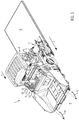
- FIG. 2 shows Fig. 2 in that an optical projector 9 is fastened to the front of the pusher 4.
- the projector 9 is configured to produce at least one projection 10 visible to the driver on the ground U in the direction of installation F, laterally and / or in front of the chassis 3 of the paver 1, in the visible spectrum.
- Fig. 2 indicates that the projection 10 may be any optical, visible to the driver of the paver 1 light image on the ground U to indicate an orientation of the paver 1, in particular with regard to a predetermined reference, the driver of the paver 1.
- the projection 10 may be a spot of light or an illuminated line on the substrate U. In the following, however, other photos / projections 10 on the underground U are also explained as navigation aid.
- the projector 9 comprises according to Fig. 2 a bracket 11 which is fixed at one end to the pusher 4 and at the other, laterally outwardly offset end carries a light source 12.
- the light source 12 may be, for example, an LED unit or a laser unit, in particular a laser pointer, a line laser or a cross-line laser.
- an arrow 13 shows that the projector 9 is mounted transversely to the mounting direction F at different distances to the pusher 4 adjustable.
- the light source 12 directly above a laterally provided on the paver reference, for example, a guideline R according to FIG. 1 to align so that the projection 10 is vertically scanned for the underlying reference.
- a reference for example, would be guided under the light source 12 guideline R, an edge of the substrate U, an edge a already built next to cold or hot paving, a projecting another road finisher or the like in question.
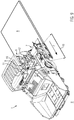
- Fig. 3 shows the paver 1 according to another embodiment.
- the projector 9 is attached to the chassis 3 of the paver 1. This ensures that the projector 9 moves closer to the control station 6 of the paver 1, whereby the driver from the control station 6, if necessary, better recognize and track the projection 10 on the ground U.
- Fig. 3 shows that the light source 12 of the projector 9 is formed as a line laser, so that the projection 10 on the substrate U represents an illuminated guide line.
- the holder 11 may be adjustably mounted to the chassis 3 to adjust the light source 12 at a desired lateral distance from the chassis 3 above the ground U.
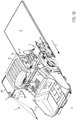
- Fig. 4 shows a further embodiment of the paver 1.
- the projector 9 is attached to a rearview mirror 14 of the paver 1.
- the rearview mirror 14 is mounted on a roof structure 15 of the paver 1.
- the light source 12 of the projector 9 emits light rays in the direction of the underground U in order to visually represent the projection 10 for a driver of the paver 1 on the ground.
- the respective projectors 9 can be moved from their use position to a rest position for a transfer or transport journey. In the rest position, the projectors 9 are stowed tightly against the chassis 3 or on the pusher 4 and / or blocked.
- the holder 11 of the projector is mounted on a lower edge of a rear mirror 14, wherein indicated by the arrow 13 that the light source 12 is mounted relative to the rear mirror 14 outwardly transversely to the mounting direction F adjustable.
- the projection 10 can therefore be imaged at different locations below on the substrate U. It would also be conceivable for the holder 11 of the projector 9 to be coupled to a mirror holder 16 in order to arrange the projector 9 optionally on the rear side 14 'of the rear mirror 14.
- Fig. 4 also shows that the viewed opposite to the mounting direction F back 14 'of the rearview mirror 14, a display unit 17, which may be formed as Einweiseampel has.
- a preceding vehicle such as a feeder and / or a material delivery vehicle, navigation signals can be given.
- FIG. 4 shown multifunctional rearview mirror projector system may be provided on both sides of the roof structure 15.
- projectors 10 can be shown on the substrate U to the left and right of the paver 1 along the installation direction F.
- a further embodiment of the paver 1 is shown.
- Projectors 9 are mounted on a hood 18 of the paver 1.
- the engine hood 18 is inclined towards the ground U as viewed from the control station 6, so that the projectors 9 mounted thereon can project the projecting devices 10 well over the underground U via the previously stored goods bunker 2.
- the hood 18 provides a stable base for mounting the projectors 9.
- the respective light sources 12 are in Fig. 5 attached by means of a U-shaped bracket 11 'on the hood 18.
- the arrow 13 points in Fig. 15 that the light sources 12 are slidably mounted on the hood 18 relative to the respective brackets 11 '.
- the attachment of the respective projectors 9 on the engine compartment 18 offers above all the advantage that the light sources 12 can not be damaged by close to the paver 1 passing vehicles. This variant also allows the projectors 9 to remain on the engine hood 18 of the paver 1 during transport journeys or transfer trips.
- Fig. 6 shows a further embodiment of the road finisher.
- the roof structure 15 carries a canopy 19.
- the projectors 9 integrally installed on the canopy 19.
- the canopy 19 can protect the projectors 9 from rain and sunlight.
- the projectors 9 are arranged at outer ends of a front side 20 of the protective roof 19.
- the front side 20 is seen in the installation direction F down to the substrate U inclined so that the projectors 9, in particular their light sources 12, may be arranged on the forwardly inclined surface of the front side 20, that the projections 10 well on the ground U are representable.
- the respective projectors 9 are not seen from a bird's eye view, because they are covered by the canopy 19 of the paver 1, that is integrally installed therein.
- the front side 20 has at its outer ends for the projectors 9 translucent window 21 through which emitted light beams of the projectors 9 reach the substrate U.
- Fig. 7 shows a further embodiment of the paver 1.
- a laterally displaceable projector 9 installed in the canopy 19 of the paver 1.
- the projector 9 is according to Fig. 7 mounted on a guideway 22 and transversely along it of the arrow 13 slidably mounted in the canopy 19.
- the protective roof 19 preferably has a translucent window 21 'over the entire width of the front side 20, through which the light beams for generating the projection 10 can be directed onto the substrate U in front of the goods bunker 2.
- the projector 9 can be adjusted by the driver along the roadway 22 from the operating station 6. In this case, the driver can adjust the position of the projector 9 by means of a control panel 23 which is available to him on the control station 6.
- the paver 1 off Fig. 7 further includes a driver's seat 24.
- the driver's seat 24 is disposed behind the control panel 23 on the control station 6.
- Fig. 7 shows an arrow 25 that the driver's seat 24 and / or the control panel 23 are mounted transversely displaceable on the control station 6.
- the driver's seat 24 and the control console 23 can be moved transversely together on the control station 6.
- the projector 9 off Fig. 7 be configured such that it automatically adjusts along the roadway 22 in dependence on the position of the driver's seat 24 and / or the operating console 23 arranged below it in the operating station 6. This ensures that the projector 9 off Fig.
- Fig. 8 shows a further embodiment of a paver 1.
- the light source 12 of the projector 9 is arranged above the canopy 19.
- Fig. 8 shows further that of the light source 12 a plurality of projectors 10 both the side of the paver 1, as well as in front of the road paver 1 on the substrate U are shown.
- the light source 12 of the projector 9 is supported by the bracket 11, which is mounted on the canopy 19.
- the holder 11 may be formed as a telescopic rod to vary the height of the light source 12 relative to the canopy 19 can.
- Fig. 9 shows a further embodiment of a paver 1.
- the projector 9 is arranged laterally on the canopy 19.
- the projector 9 is mounted laterally along the arrow 13 on the canopy 19 by means of the bracket 11 sideways.
- the projector 9 can be positioned cantilevered sideways in this embodiment, it does not hinder the work at the side of the paver in this altitude.
- Fig. 10 shows a further embodiment of a paver 1.
- the protective roof 19 comprises a pull-out roof 25 which, viewed transversely to the installation direction F, can be extended sideways along an arrow 26.
- the projector 9 at a front outer end of the pull-out roof 25 is arranged.
- the projector 9 is preferably integrally installed in the pull-out roof 25 and can be protected by its installation in the pull-out roof 25 from bad weather conditions.
- the pull-out roof 25 is used according to Fig. 10 for the projector 9 as a holder and determines how far the projector 9 is laterally spaced from the canopy 19. From the pull-out roof 25, the projector 9 can be positioned above the ground U in such a way that the respective projectors 10 can be displayed in a clearly visible manner next to the road paver 1 on the ground U. In the embodiment in Fig. 10 both extendable roofs 25 have the projector 9 integrally installed.
- Fig. 11 shows a further embodiment of a paver 1.
- the projector 9 is arranged on the screed 7.
- Fig. 11 shows that the projector 9 is attached to a side slider 27 of the screed 7. From the projector 9, the projection 10 can be displayed laterally of the side slider 27 and / or in front of the side slider 27, according to the invention in alignment with the side slider 27 on the substrate U.
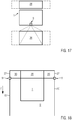
- Fig. 12 shows the screed 7 Fig. 11 in a particular embodiment.
- the screed 7 is configured as a pull-out screed 28.
- the pull-out screed 28 allows a variable paving width 29 for the new paving layer B.
- the pull-out screed 28 comprises hydraulically adjustable pull-out parts 30, which are laterally adjustable transversely to the installation direction F according to the desired paving width 29.
- the side pushers 27 are attached, which above all ensure that a clean end edge 31 in the new road surface B can be produced.
- the respective projectors 9 are arranged on the two side slides 27, that the respective projections 10 with the two side slides 27 can be imaged according to the invention on the substrate U.
- the embodiment according to Fig. 12 has the advantage that the respective projections 10 are correspondingly reoriented by adjusting the pull-out parts 30 on the substrate U, ie automatically following the setting of the pull-out screed 28.
- the aligned with the respective side sliders 27, shown on the substrate U projections 10 form for the driver of the road finisher 1 a visual extension of the side shift 27 on the substrate U, so that it is better with respect to the projecting 10 orientation / orientation of the paver 1 with respect to Assess installation direction F. can.
- the driver can recognize on the basis of the aligned lines where the new road surface B is laid out when the paver 1 is currently being steered.
- Fig. 13 shows a schematic horizontal projection (top view) of the paver 1 according to the invention in this embodiment, the projector 9 is laterally attached to the canopy 19 and configured to image the projection 10 in dependence on a positioning of the pull-30 on the substrate U.
- Fig. 13 in a schematic representation that the road paver 1 has a control unit 33 which is functionally connected to a sensor unit 33 and to the projector 9.
- the sensor unit 33 is configured to detect a position of the extension parts 30 and to forward it to the control unit 33.
- the control unit 32 can control the projector 9 in such a way that the projections 10 it displays on the ground U are aligned with the respective side slides 27.
- the embodiment variant Fig. 13 is thus able to image the projections 10 as a function of the position of the side slides 27 on the substrate U, wherein an adjustment of the projections 10 carried out laterally along the arrow 34 can take place automatically in synchronism with an adjustment of the pull-out parts 30.
- the embodiment variant Fig. 13 offers the advantage that on the paver 1 different Ausziehbohlentypen together with the projectors 9 are used.
- Fig. 14 It is shown how two road pavers 1 track to train new road coverings B1 and B2 block side by side.
- Fig. 14 shows that the projectors 10 of the respective projectors 9 of the paver 1 are aligned with each other, in particular along a portion A are overlapping with each other.
- the lines generated on the substrate U by means of the aligned projecting 10 allows the respective drivers of the paver 1 a precise route guidance along the mounting direction F.
- Fig. 14 can be directed to a two paver 1 in the light of a reference, for example, given a guideline R.
- This road paver 1 therefore specifies the direction of installation F for the other paver 1 and is considered to be the reference transmitter for the adjoining paver 1.
- the projecting make it possible that the two road pavers 1 drive parallel to each other.
- Fig. 15 shows a further schematic representation in plan view of the road paver 1 according to the invention.
- the projectors 10 on the ground U not only for the driver of the paver 1 represent a visual navigation aid, but also for the driver of a preceding material delivery vehicle 34, such as a feeder or a truck, which drove in front of the Gutbunker 2 of the paver 1.
- the projections 10 provide a navigation aid for the truck driver when he reverses the truck against the pusher 4 (see Fig. 2 ) approaches the paver 1.
- the projectors 10 stretch in Fig. 15 a position field 35 within which the material delivery vehicle 34 should navigate in order to provide a proper material transfer to the paver 1.
- Fig. 16 shows another schematic plan view of a road paver 1.
- Fig. 16 are the respective projectors 9, as the projector 9 off Fig. 9 , attached to the protective roof 19 of the paver 1.
- the paver 1 of the Fig. 16 is equipped with the Extending Boom 28.
- the projectors 9 can be adjusted laterally transversely to the direction of installation F, so that the projectors 10 can be imaged perpendicular to the substrate U from the respective light source 12.
- the projections 10 are adjusted according to the invention with the side sliders 27 of the extension parts 30 in alignment.
- Fig. 17 shows another schematic plan view of a road paver 1.
- the paver 1 is equipped with the pull-out screed 28.
- the projector 9 is in Fig. 17 according to the embodiment of Fig. 7 or 8th arranged on the canopy 19.
- the projector 9 off Fig. 17 is configured to project in front of the paver 1 in installation direction F, to project an orientation field 36 on the ground.
- Fig. 17 shows that the orientation field 36 in width to the installation width of the Ausziehbohle 28 is adaptable.
- the orientation field 36 represents for the driver of the paver a visual extension of the paver on the ground U, so that he can better estimate the orientation of the paver 1 with respect to a reference or the environment.
- Fig. 18 shows a further schematic plan view of the road paver according to the invention 1.
- the respective projections 10 represent a visual extension of the side shifters 27 along the mounting direction F.
- the visually displayed for the driver of the paver 1 on the substrate U projections 10 give the driver a navigation aid that allows improved navigation of the paver 1 especially during the installation mode.
- the projections 10 are also visible to other operating personnel along the installation track. For the other operator set the projectors 10 warning light barriers that limit a danger area around the paver 1.
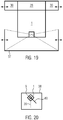
- Fig. 19 shows a further schematic plan view of the road finisher according to the invention 1.
- the road paver 1 off Fig. 19 is the projector on the canopy 19 as in the FIGS. 7 or 8th arranged.
- the projector 9 off Fig. 19 is adapted to image in areas laterally and in front of the paver 1 a light frame 36 on the substrate U, the lateral lines are particularly adaptable in terms of the extension parts 30 of the pullout 28.
- the driver of the paver 1 can navigate well and steer the paver 1 along the predetermined installation direction F, in particular with regard to a given reference.
- Fig. 20 shows a schematic representation of a display unit 38, which is available to the driver on the control station 6 of the paver 1.
- Fig. 20 is visually the paver 1 with respect to the projection 10 shown on the display unit 38, which represents an instantaneous orientation of the paver 1 on the substrate U.
- Fig. 20 further shows a target orientation 39, along which the paver 1 should be aligned to comply with the new road surface B along the predetermined mounting direction F.
- Fig. 20 does not show the current orientation (projection 10) of the paver 1 in the desired installation direction F (target orientation 39).
- the driver of the paver 1 must counter-steer in order to shift the projection 10 to the target orientation 39. He can follow the countersteering on the display unit 38.
- the paver 1 has reached the predetermined installation direction F and can continue installation in this direction.
- An additional navigation aid could be offered to the driver by means of the display unit 38, if in different orientations of the projection 10 and the target orientation 39 both lines are shown in red on the display unit 38 and both lines are green as soon as the projection 10 falls to the target orientation 39.
Description
Die vorliegende Erfindung betrifft einen Straßenfertiger gemäß dem Anspruch 1.The present invention relates to a road paver according to
Bei bekannten Straßenfertigern der Vögele AG, beispielsweise am Fertiger des Typs Super 700, ist an dem Fahrwerk ein mechanischer Zeiger als Navigationshilfe befestigt. Der mechanische Zeiger umfasst eine Halterung, die seitlich des Raupenfertigers eine Pendelkette bzw. einen Flachstahl über dem Untergrund trägt. Während der Einbaufahrt kann der Fahrer den Straßenfertiger derart lenken, dass die Pendelkette bzw. der Flachstahl entlang der Einbaustrecke an oder zumindest sehr nahe an einer zur Vorgabe einer gewünschten Einbaurichtung gespannten Referenzschnur, entlang des Bordsteins oder einer Fräskante geführt wird.In known road pavers of the Vögele AG, for example on the Super 700 paver, a mechanical pointer is attached to the landing gear as a navigation aid. The mechanical pointer comprises a holder which carries a pendulum chain or a flat steel above the substrate on the side of the tracked paver. During the installation drive, the driver can steer the paver in such a way that the pendulum chain or the flat steel is guided along the installation path or at least very close to a reference line stretched to specify a desired installation direction, along the curb or a milling edge.
Es hat sich allerdings gezeigt, dass der mechanische Richtungsanzieger durch die mechanischen Eigenschaften eine begrenzte Einsatzmöglichkeit bietet bzw. einen begrenzten Arbeitsradius hat. Desweiteren ist der übliche Arbeitsbereich am Straßenfertiger mit Störgeometrien versehen, z.B. Bunkerwänden, Abdruckbalken, Fahrbereich des LKW. Als Hauptnachteil des mechanischen Zeigers gilt, dass dieser durch äußere Einwirkung verstellt werden kann, z.B. hochstehende Kanaldeckel, fahrende LKW's, Personal welches dagegen stößt.However, it has been shown that the mechanical directional winner offers a limited field of application due to the mechanical properties or has a limited working radius. Furthermore, the usual work area on the paver is provided with Störgeometrien, e.g. Bunkerwänden, impression beam, driving range of the truck. The main disadvantage of the mechanical pointer is that it can be adjusted by external action, e.g. high-level manhole covers, moving trucks, staff who bumps against it.
Der seitlich auskragende mechanische Zeiger kann ebenfalls von einem Fahrer eines vorrausfahrenden LKWs für einen Materialübergabevorgang verwendet werden, um den LKW rückwärts mittig an den Gutbunker des Fertigers heranzufahren. Problematisch wird der Einsatz des mechanischen Zeigers aber spätestens dann, wenn nachts mit dem Straßenfertiger gearbeitet wird, weil der Fahrer bei Dunkelheit vom Bedienstand aus die Pendelkette bzw. der Flachstahl nicht mehr gut erkennen kann.The laterally cantilevered mechanical pointer can also be used by a driver of a preceding truck for a material handover operation to bring the truck backward centered to the dig bin of the paver. The use of the mechanical pointer but at the latest when working with the paver at night, because the driver in the dark from the control console from the control of the pendulum chain or flat steel can no longer recognize well.
Hinzu kommt, dass sich der Fahrer vom Bedienstand aus leicht darüber täuschen kann, wie nahe die Pendelkette bzw. den Flachstahl tatsächlich an der Richtschnur geführt wird. Oftmals können erst größere Abstände bzw. Abweichungen zwischen der Pendelkette bzw. dem Flachstahl und der Richtschnur vom Bedienstand aus wahrgenommen werden. Dies führt allerdings dazu, dass erst recht spät einem unerwünschten Einbauverlauf entgegen gelenkt wird, wodurch es zu Einbaufehlern kommen kann und gegebenenfalls aufwendig nachgebessert werden muss.In addition, it is easy for the driver to be fooled by the operator's position as to how close the pendulum chain or the flat steel is actually guided to the guideline. Often only larger distances or deviations between the pendulum chain or the flat steel and the guideline can be perceived from the control station. However, this leads to the fact that a very late unwanted installation course is directed against, which can lead to installation errors and may need to be carefully reworked.
Aufgabe der Erfindung ist es, einen Straßenfertiger zur Verfügung zu stellen, der durch den Einsatz einfacher, konstruktiver technischer Mittel besser entlang einer gewünschten Einbaustrecke navigierbar ist.The object of the invention is to provide a paver available, which is navigable through the use of simple, constructive technical means better along a desired installation distance.
Diese Aufgabe wird gelöst durch einen Straßenfertiger gemäß dem Anspruch 1. Verbesserte Weiterbildungen der Erfindung sind in den Unteransprüchen angegeben.This object is achieved by a paver according to
Der erfindungsgemäße Straßenfertiger umfasst einen Gutbunker zur Aufnahme eines Einbaumaterials, ein Chassis, einen Bedienstand, der in Einbaurichtung gesehen hinter dem Gutbunker angeordnet ist, eine nivellierbare Einbaubohle zum Verbau des Einbaumaterials auf einem Untergrund, eine Materialfördereinheit, die dazu konfiguriert ist, das Einbaumaterial vom Gutbunker zur Einbaubohle zu transportieren sowie mindestens einen optischen Projektor.The paver according to the invention comprises a Gutbunker for receiving a built-in material, a chassis, an operator's station, which is arranged behind the Gutbunker seen in the installation direction, a leveling screed for installation of the paving material on a substrate, a material handling unit, which is configured, the paving material from Gutbunker to transport to the screed and at least one optical projector.
Bei der Erfindung ist der optische Projektor dazu konfiguriert, auf dem Untergrund in Einbaurichtung gesehen seitlich und/oder vor das Chassis des Straßenfertigers mindestens eine Projizierung im sichtbaren Spektrum (d.h. im Wellenlängenbereich von ca. 400 bis 800 nm) zu erzeugen, wobei die Projizierung vom Bedienstand aus in Einbaurichtung gesehen von einem Fahrer des Straßenfertigers einsehbar ist.In the invention, the optical projector is configured to generate at least one projecting in the visible spectrum (ie in the wavelength range of about 400 to 800 nm) on the ground in the direction of installation laterally and / or in front of the chassis of the paver, the projecting of Control station seen in the installation direction of a driver of the paver is visible.
Bei der Erfindung bildet die optische Projizierung auf dem Untergrund eine Steuer- bzw. Navigationshilfe, mittels welcher insbesondere dem Fahrer auf dem Bedienstand des Straßenfertigers anzeigbar ist, wie der Straßenfertiger für den Einbaubetrieb ausgerichtet ist. Die Projizierung kann bei sämtlichen Wetterbedingungen sowohl tagsüber, als auch bei Nachtarbeiten gut als Navigationshilfe zum Lenken des Straßenfertigers entlang einer gewünschten Einbaurichtung eingesetzt werden.In the invention, the optical projection on the ground forms a control or navigation aid, by means of which in particular the driver on the control station of the paver is displayed, as the paver is aligned for the installation operation. The projecting can be used well as a navigation aid for steering the paver along a desired mounting direction in all weather conditions both during the day and at night work.
Anhand der optischen Projizierung kann der Fahrer schnell erkennen, ob er den Straßenfertiger entlang der vorbestimmten Einbaurichtung lenkt oder nicht. Deshalb kann schnell reagiert werden, wenn der Straßenfertiger von der vorbestimmten Einbaurichtung abkommt.On the basis of the optical projection, the driver can quickly recognize whether he steers the paver along the predetermined installation direction or not. Therefore, it can be reacted quickly when the paver departs from the predetermined installation direction.
Bei der Erfindung wird der Untergrund als Projektionsfläche genutzt, auf welchem der Straßenfertiger gelenkt wird. Gewöhnlicherweise ist der Untergrund vorbearbeitet, beispielsweise eingeebnet und/oder vorverdichtet, um darauf mittels des Straßenfertigers eine neue Einbauschicht zu verlegen. Der Untergrund als Projektionsfläche zeigt dem Fahrer die Projizierung derart deutlich an, dass der Fahrer vom Bedienstand aus gut nachverfolgen kann, wie der Straßenfertiger tatsächlich auf dem Untergrund ausgerichtet ist. Die Projizierung als solche ist aber auch für anderes Bedienpersonal auf der Baustelle hilfreich und kommt ebenfalls als Navigationshilfe für andere Baustellenfahrzeuge in Frage, beispielsweise einen Beschicker und/oder einen LKW, der Einbaugut in den Gutbunker des Straßenfertigers kippt.In the invention, the substrate is used as a projection surface on which the paver is steered. Usually, the substrate is pre-processed, for example, leveled and / or pre-compacted to lay on it by means of the paver a new installation layer. The ground as a projection surface shows the driver the projecting so clearly that the driver can track well from the control station, as the paver is actually aligned on the ground. However, the projecting as such is also helpful for other operators on site and also comes as a navigation aid for other construction vehicles in question, such as a feeder and / or a truck tipping the property in the Gutbunker the paver.
Vorteilhaft ist es auch, dass die Projizierung auf dem Untergrund auch ohne eine gespannte Referenzschnur als brauchbare Navigierungshilfe für den Fahrer des Straßenfertigers einsetzbar ist. Insbesondere kann der Projektor als Navigationshilfe unterschiedliche gut sichtbare Projektsmuster, beispielsweise Linien, auf dem Untergrund abbilden. Hinsichtlich einer bekannten mechanisch geführten punktuellen Aufnahme der Position des Straßenfertigers mittels der Pendelkette bzw. des Flachstahls ist insbesondere eine optische Linienführung durch den Einsatz eines Linienlasers als Projektor hilfreich, damit das Bedienpersonal auf der Baustelle die aktuelle Position des Straßenfertigers gut beobachten kann. Dies wird vor allem später im Zusammenhang mit den Erläuterungen zu den Figuren gezeigt.It is also advantageous that the projection on the ground can be used without a strained reference cord as a useful navigation aid for the driver of the paver. In particular, the projector can be used as a navigation aid different well-visible project pattern, such as lines, depict on the ground. With regard to a known mechanically guided selective recording of the position of the paver by means of the pendulum chain or the flat steel in particular an optical lines by using a line laser as a projector is helpful so that the operator can observe the current position of the paver on the job site well. This is especially shown later in connection with the explanation of the figures.
Der Projektor kann an unterschiedlichen Stellen am Straßenfertiger befestigt sein. Vorzugsweise ist der Projektor am Chassis, an einer Schubvorrichtung, am Bedienstand, an einem Dachaufbau des Bedienstandes, an einem Schutzdach, an einem Ausziehdach, an einem Rückspiegel, auf einer Motorhaube, in oder an einer Einweiseampel, d.h. einer Anzeigevorrichtung für den Materialübergabevorgang, an einem Seitenschieber und/oder an der Einbaubohle des Straßenfertigers angeordnet. Gegenüber dem bekannten mechanischen Zeiger kann der bei der Erfindung eingesetzte optische Projektor an viel mehr Stellen des Straßenfertigers befestigt sein. Insbesondere kann der Projektor derart am Straßenfertiger montiert werden, dass eine Kollision des Projektors mit beweglichen Baugruppen des Straßenfertigers, beispielsweise mit Bunkerwänden, einem Abdruckbalken, Hydraulikzylindern, Raupenketten und/oder einem Vorabstreifer, vermieden werden kann. Im Gegensatz zur Erfindung ist der bekannte mechanische Zeiger hinsichtlich der Anbringung am Straßenfertiger darauf beschränkt, nicht weit entfernt vom Untergrund, üblicherweise am Andruckbalken oder am Fahrwerk des Raupenfertigers, befestigt zu sein, damit die Pendelkette bzw. der Flachstahl kurz ausgebildet sein kann, um nicht zu schwer zu sein. Allerdings musste der bekannte mechanische Zeiger für Umsetz- bzw. Transportfahrten des Raupenfertigers vom Andruckbalken oder vom Chassis abmontiert werden. Es kann vorkommen, dass das Baustellenpersonal über den am Boden auskragenden mechanischen Zeiger stolpert und sich verletzt.The projector can be attached to the paver at different locations. Preferably, the projector is mounted on the chassis, on a pusher, on the operator's cab, on a roof structure of the operator's cab, on a canopy, on a pull-out roof, on a rearview mirror, on a hood, in or on a pylon, i. a display device for the material transfer process, arranged on a side shifter and / or on the screed of the paver. Compared with the known mechanical pointer of the optical projector used in the invention can be attached to many more places of the paver. In particular, the projector can be mounted on the paver such that a collision of the projector with moving assemblies of the paver, such as bunker walls, an impression beam, hydraulic cylinders, caterpillar tracks and / or a Vorabstreifer can be avoided. In contrast to the invention, the known mechanical pointer with respect to the attachment to the paver is limited not far away from the ground, usually on Andruckbalken or on the chassis of the tracked paver to be attached, so that the pendulum chain or the flat steel can be formed short, not to too hard to be. However, the known mechanical pointer for transfer or transport of the tracked paver had to be removed from the pressure bar or the chassis. It can happen that the construction site personnel stumble over the grounding mechanical pointer and injure themselves.
Der Projektor kann für seinen Einsatzzweck, d.h. zur Erzeugung einer Projizierung auf dem Untergrund, vielerorts am Straßenfertiger zu befestigen sein. Insbesondere kann der Projektor für Umsetz- und Transportfahrten an seinem Einsatzort am Straßenfertiger verbleiben, sofern er nicht in unmittelbarer Nähe zum Untergrund positioniert ist. Selbst wenn der optische Projektor im Bereich des Andruckbalkens bzw. des Fahrwerks des Straßenfertigers befestigt ist, kann er vorzugsweise für den Transport des Straßenfertigers derart in eine Ruhestellung eingefahren werden, dass er den Transport bzw. das Umsetzen des Straßenfertigers nicht stört.The projector can be used for its purpose, ie to produce a projection on the ground, in many places to attach to the paver. In particular, the projector for Transfer and transport trips remain at his place of use on the paver, provided he is not positioned in the immediate vicinity of the ground. Even if the optical projector is mounted in the area of the pressure beam or the chassis of the paver, it can preferably be retracted for the transport of the paver in a rest position so that it does not interfere with the transport or the implementation of the paver.
Vorstellbar wäre es auch, dass die Einbaubohle eine Ausziehbohle mit seitlich verstellbaren Ausziehteilen ist, wobei der Projektor an einem Ausziehteil befestigt ist. Vom Ausziehteil aus kann der Projektor hervorragend auf den Untergrund seitlich des Chassis des Straßenfertigers, d.h. in Einbaurichtung gesehen vor die Einbaubohle gerichtet werden, um an beliebiger Stelle seitlich des Chassis die Projizierung auf dem Untergrund abzubilden. Eine zusätzliche auskragende Halterung ist dafür nicht notwendig.It would also be conceivable that the screed is a Ausziehbohle with laterally adjustable Ausziehteilen, the projector is attached to a pull-out. From the pull-out section, the projector can project perfectly onto the ground to the side of the chassis of the paver, i. Seen in the direction of installation in front of the screed are directed to reflect anywhere on the side of the chassis, the projection on the ground. An additional cantilevered bracket is not necessary for this.
Zur Anbringung des Projektors käme insbesondere ein Seitenschieber der Einbaubohle, insbesondere ein Seitenschieber eines Ausziehteils einer Ausziehbohle in Frage, von welchem aus die Projizierung gut auf den Untergrund seitlich des Chassis des Straßenfertigers herstellbar ist.For mounting the projector, in particular a side slide of the screed, in particular a side slide of an extension of a Ausziehbohle in question, from which the projecting is well produced on the ground side of the chassis of the paver.
Für den Einsatz auf der Baustelle ist der Projektor erfindungsgemäß manuell und/oder automatisch ausrichtbar, um die Projizierung bezüglich einer gewünschten Referenz einzustellen. Damit kann der Fahrer bei Arbeitsbeginn den Straßenfertiger entsprechend der vorbestimmten Einbaurichtung ausrichten und dann den Projektor so einstellen und justieren, dass die Projizierung auf die Referenz fällt.For use on the construction site, the projector can be aligned manually and / or automatically in accordance with the invention in order to set the projection with respect to a desired reference. This allows the driver at work to align the paver according to the predetermined installation direction and then adjust the projector and adjust so that the projection falls on the reference.
Als Referenz käme in einer nicht zur Erfindung gehörenden Ausführung der Einsatz einer entlang der Einbaustrecke gespannten Richtschnur in Frage, wobei sich die Erfindung auch ohne den Einsatz einer solchen Richtschnur bewährt hat. Vorstellbar wäre es auch, dass als Referenz eine äußere Kante einer bereits daneben ausgelegten kalten oder heißen Einbaubahn, eine Kante der Untergrundschicht und/oder eine Spur im Untergrund, worauf der Straßenfertiger fährt, verwendbar ist.As a reference, in an embodiment not belonging to the invention, the use of a straightening line stretched along the built-in stretch would be considered, whereby the invention has also proven itself without the use of such a guide. It would also be conceivable that the reference can be an outer edge of a cold or hot installation track already laid next to it, an edge of the background layer and / or a track in the ground on which the road paver travels.
Möglich ist es auch, dass die Projizierung eine andere Projizierung als Referenz verwendet, d.h. zu einer anderen Projizierung ausrichtbar ist und gegebenenfalls zumindest teilweise mit dieser zusammenfällt. Diese nicht erfindungsgemäße Ausführung könnte dann vorteilhaft sein, wenn mehrere Straßenfertiger in Einbaurichtung gesehen versetzt nebeneinander "heiße Bahn an heiße Bahn" einbauen. Dabei könnte es sein, dass der äußerste Straßenfertiger als Referenz eine gespannte Referenzschnur zum Einbau verwendet und für den anderen daneben, auf der anderen Seite einbauenden Straßenfertiger eine Projizierung als Referenz auf dem Untergrund abbildet, an welcher sich dieser Straßenfertiger orientieren kann. Dieses Prinzip der mittelbaren Referenzübergabe lässt sich auf beliebig viele Straßenfertiger ausbauen.It is also possible for the projection to use a different projection as a reference, ie to be able to be aligned with another projection and possibly coincide at least partially with it. This embodiment not according to the invention could be advantageous if several road pavers, as seen in the direction of installation, installed next to one another "hot web to hot web". It could be that the outermost paver used as reference a strained reference cord for installation and for the other next, on the other side installing paver a projection as a reference on the ground at which this is Paver can orient. This principle of indirect reference transfer can be extended to any number of road pavers.
Erfindungsgemäß jedoch ist die Referenz ein Seitenschieber der Einbaubohle, wobei die Projizierung eine Führungslinie ist, die mit dem Seitenschieber in Einbaurichtung fluchtet. Dabei gilt, je länger die Führungslinie vom Seitenschieber aus in Fahrtrichtung gesehen auf den Untergrund projiziert wird, desto einfacher kann der Fahrer vom Bedienstand aus eine Orientierung des Straßenfertigers entlang einer vorgegebenen Einbaustrecke einschätzen. Die Führungslinie bietet somit für den Fahrer des Straßenfertigers eine visuelle Navigierungshilfe, um den Straßenfertiger entlang einer gewünschten Einbaustrecke zu navigieren. Da der Seitenschieber im Wesentlichen das Maß für die Einbaubreite des neuen Straßenbelags festlegt, kann erfindungsgemäß die Führungslinie als visuelle Verlängerung des Seitenschiebers dafür benutzt werden, dem Fahrer des Straßenfertigers anzuzeigen, wohin die neue Fahrbahn verlegt wird, wenn er die Fahrtrichtung beibehält. Somit kann der Fahrer anhand der projizierten Führungslinie schnell erkennen, ob er der aktuellen Fahrtrichtung des Straßenfertigers entgegensteuern muss oder nicht.According to the invention, however, the reference is a side shifter of the screed, wherein the projection is a guide line which is aligned with the side shifter in the installation direction. In this case, the longer the guide line is projected from the side slider seen in the direction of travel on the ground, the easier the driver can estimate from the operating position of an orientation of the paver along a predetermined installation distance. The leader thus provides the driver of the paver with a visual navigational aid to navigate the paver along a desired route. Since the sideshift defines essentially the dimension of the paving width of the new road surface, according to the invention the guide line can be used as a visual extension of the sideshift to indicate to the driver of the road finisher where the new roadway will be laid if he maintains the direction of travel. Thus, the driver can quickly recognize on the basis of the projected guide line, whether he must counteract the current direction of travel of the paver or not.
Vorteilhaft wäre es auch, wenn der Straßenfertiger eine Steuereinrichtung umfasst, die mit dem Projektor sowie mit einer Erfassungseinheit zur Detektion der Einbaubreite funktional verbunden ist sowie dazu konfiguriert ist, die Projizierung automatisch und synchron zur Einbaubreite derart zu verstellen, dass die Projizierung fluchtend zum Seitenschieber eingestellt bleibt. Alternativ oder zusätzlich kann der Fahrer auch manuell eine Einstellung am Projektor und/oder an einem Bedienpult des Straßenfertiger vornehmen, um die Projizierung dementsprechend anzupassen. Gemäß einer anderen raffinierten Ausführungsform umfasst der Straßenfertiger auf dem Bedienstand einen quer zur Einbaurichtung verschiebbar gelagerten Fahrersitz, wobei der Projektor an einem Schutzdach des Straßenfertigers angeordnet ist und entlang einer am Schutzdach ausgebildeten Führungsbahn manuell und/oder automatisch oberhalb einer Position des Fahrersitzes positionierbar ist. Vom Projektor aus kann die Projizierung in Einbaurichtung gesehen, vor dem Fahrer und dem Gutbunker auf dem Untergrund abgebildet werden. Bei dieser Ausführungsform wandert somit die Projizierung auf dem Untergrund gemäß der Ausrichtung des Fahrersitzes auf dem Straßenfertiger mit. Die Projizierung bleibt daher für den Fahrer unabhängig von der Positionierung seines Fahrersitzes stets gut einsehbar.It would also be advantageous if the paver comprises a control device which is functionally connected to the projector and to a detection unit for detecting the installation width and is configured to adjust the projection automatically and synchronously with the pave width so that the projection is aligned with the side pusher remains. Alternatively or additionally, the driver can also manually make a setting on the projector and / or on a control panel of the paver to adjust the projection accordingly. According to another refined embodiment, the paver comprises on the operating stand a driver seat which is displaceably mounted transversely to the installation direction, the projector being arranged on a protective roof of the paver and being manually and / or automatically positionable above a guideway formed on the protective roof above a position of the driver's seat. From the projector, the projection can be seen in the direction of installation, be displayed in front of the driver and the Gutbunker on the ground. Thus, in this embodiment, the projecting on the ground in accordance with the orientation of the driver's seat on the paver with. The projection therefore always remains easily visible to the driver regardless of the positioning of his driver's seat.
Vorzugsweise umfasst der Projektor als Lichtquelle mindestens einen Linienlaser und/oder einen Kreuzlinienlaser. Damit lässt sich die Projizierung besonders klar und deutlich auf dem Untergrund herstellen. Alternativ kann der Projektor auch zum Erzeugen der Projizierung eine LED-Einheit, eine Lichteinheit mit Fokussierlinse und/oder eine Lichteinheit einer mit zu projizierenden Markierung umfassen. Insbesondere mittels des Linienlasers kann mindestens eine in der Länge variierbare Führungslinie als Projizierung auf dem Untergrund abgebildet werden.Preferably, the projector comprises as light source at least one line laser and / or a cross-line laser. This makes it possible to produce the projection especially clearly and clearly on the ground. Alternatively, the projector may also be an LED unit, a light unit with focusing lens and / or a light unit for generating the projection a mark to be projected with. In particular, by means of the line laser at least one variable in length guide line can be projected as a projection on the ground.
Vorzugsweise ist der Projektor als gepulste Lichtquelle ausgebildet, wobei es sich vornehmlich um einen Pulslaser handelt. Insbesondere kann die Dauer der Laserpulse und/oder die Dauer der Unterbrechungen zwischen den Laserpulsen am Projektor direkt und/oder vom Bedienstand des Straßenfertigers aus einstellbar sein. Besonders gut lässt sich der Pulslaser als Navigationshilfe dann einsetzen, wenn die Laserpulse und/oder die Unterbrechungen dazwischen automatisch in Abhängigkeit einer Geschwindigkeit des Straßenfertigers anpassbar sind. Vorzugsweise ist bei Verwendung eines Lasers als Lichtquelle derselbe als Laser bis zur Geräteklasse 2 gemäß DIN EN 60825-1 ausgebildet, um augensicher für das Bedienpersonal zu sein.Preferably, the projector is designed as a pulsed light source, which is primarily a pulse laser. In particular, the duration of the laser pulses and / or the duration of the interruptions between the laser pulses on the projector can be adjustable directly and / or from the operating position of the road finisher. The pulse laser can be used particularly well as a navigation aid if the laser pulses and / or the interruptions in between are automatically adaptable as a function of a speed of the road finisher. Preferably, when using a laser as a light source, the same is designed as a laser up to
Gemäß einer bevorzugten Variante ist die Intensität des Lichts der Lichtquelle einstellbar. Vorzugsweise ist die Intensität des Lichts zur Erzeugung der Projizierung auf dem Untergrund entsprechend der Höhenposition des Projektors, mindestens eines Einbauparameters des Straßenfertigers und/oder entsprechend einer Witterungsbedingung automatisch einstellbar, ohne dabei in einen Strahlungsbereich zu geraten, der für das menschliche Auge nicht mehr augensicher ist.According to a preferred variant, the intensity of the light of the light source is adjustable. Preferably, the intensity of the light for generating the projection on the ground according to the height position of the projector, at least one installation parameter of the paver and / or automatically adjustable according to a weather condition, without getting into a radiation area that is no longer eye-safe for the human eye ,
Vorteilhaft ist es, wenn der Projektor dazu ausgebildet ist, unterschiedliche Projizierungsmuster (z.B. Linien, Kreuzlinien und/oder parallele Linien) auf dem Untergrund abbilden kann. Eine Variante sieht vor, dass der Fahrer mittels eines Bedienpults auf dem Bedienstand unterschiedliche Funktionen des Projektors ansteuern kann, insbesondere dessen Projizierungsmuster, dessen Ausrichtung, die Farbe der Projizierung und/oder die Intensität der Projizierung.It is advantageous, if the projector is designed, to be able to image different projection patterns (for example lines, cross lines and / or parallel lines) on the ground. A variant provides that the driver can control various functions of the projector by means of a control panel on the control station, in particular its projection pattern, its orientation, the color of the projection and / or the intensity of the projection.
Vorzugsweise ist der Projektor dazu konfiguriert, als Projizierung ein lineares Richtungsfeld auf dem Untergrund vor dem Gutbunker zu erzeugen. Ein derartiges Richtungsfeld könnte vom Fahrer als visuell flächige Verlängerung einer horizontalen Projektionsfläche des Straßenfertigers benutzt werden, um die Ausrichtung des Straßenfertigers besser einschätzen zu können. Eine derartige Projizierung könnte auch vorteilhaft für einen Beschickungs- und/oder Materialübergabevorgang eingesetzt werden.Preferably, the projector is configured to produce as a projection a linear directional field on the ground in front of the gut bunker. Such a direction field could be used by the driver as a visually planar extension of a horizontal projection surface of the paver in order to better appreciate the orientation of the paver can. Such a projection could also be used advantageously for a feed and / or material transfer operation.
Vorzugsweise ist der Projektor dazu konfiguriert, eine Breite des Richtungsfelds manuell und/oder automatisch anzupassen. Dies könnte beispielsweise in Anpassung an eine Einbaubreite der Einbaubohle geschehen. Die Breite des Richtungsfelds könnte somit an den Einsatz unterschiedlicher Bohlentypen angepasst werden.Preferably, the projector is configured to manually and / or automatically adjust a width of the direction field. This could happen, for example, in adaptation to a pave width of the screed. The width of the directional field could thus be adapted to the use of different screed types.
Besonders hilfreich für den Fahrer des Straßenfertigers ist es, wenn der Straßenfertiger eine Displayeinheit umfasst, die dazu konfiguriert ist, eine horizontale Projektion des Straßenfertigers, einschließlich der Projizierung relativ zu einer Referenz und/oder einer Zielvorgabe anzuzeigen. Dafür wäre insbesondere eine Fadenkreuzdarstellung verwendbar. Somit behält der Fahrer einen Überblick darüber, in welcher Richtung sich der Straßenfertiger bezüglich der Referenz bewegt.Particularly helpful to the paver driver is when the paver includes a display unit configured to display a horizontal projection of the paver, including projecting relative to a reference and / or a target. In particular, a crosshair representation would be usable. Thus, the driver retains an overview of which direction the paver is moving with respect to the reference.
Besonders gut lässt sich der Straßenfertiger dann navigieren, wenn der Straßenfertiger auf jeder Seite einen Projektor aufweist. Es können dann auf beiden Seiten des Chassis Projizierungen auf dem Untergrund dargestellt werden.The paver can be navigated particularly well if the paver has a projector on each side. It can then be displayed on both sides of the chassis projecting on the ground.
Vorzugsweise ist der Projektor bei einem Wechsel zwischen einem Einbau- und einem Transport- und/oder Umsetzmodus des Straßenfertigers automatisch an- und ausschaltbar. Das An- und Ausschalten des Projektors ließe sich insbesondere anhand eines spezifischen Betriebsparameters des Straßenfertigers triggern, beispielsweise anhand vom Einbau- oder Transportmodus, einer Tamperdrehzahl, Materialförderung AN/AUS, Bohlenheizung AN/AUS, usw.Preferably, the projector is automatically switched on and off when changing between a built-in and a transport and / or Umsetzmodus the paver. The turning on and off of the projector could be triggered, in particular, on the basis of a specific operating parameter of the paver, for example by means of the installation or transport mode, a tamper speed, material conveying ON / OFF, screed heating ON / OFF, etc.
Vorteilhaft wäre es auch, wenn der Projektor lösbar am Straßenfertiger befestigt ist. Der Projektor könnte somit über Nacht, während der Straßenfertiger auf der Baustelle verbleibt, von diesem entfernt werden, um zu verhindern, dass er gestohlen wird. Als lösbares Befestigungsmittel könnte der Projektor insbesondere einen Bajonettverschluss, eine Schraubenverbindung und/oder eine Magnetverbindung aufweisen.It would also be advantageous if the projector is releasably attached to the paver. The projector could thus be removed overnight while the paver is left on the job site to prevent it from being stolen. As a releasable fastening means, the projector could in particular have a bayonet closure, a screw connection and / or a magnetic connection.
Gemäß einer anderen Ausführungsvariante der Erfindung ist eine Farbe der Projizierung manuell und/oder automatisch einstellbar. Bei starker Sonneneinstrahlung wäre ein grünes Licht von Vorteil, damit die Projizierung gut erkennbar für den Fahrer des Straßenfertigers bleibt. Nachts könnte beispielsweise ein hellerer Farbton gewählt werden. Grundsätzlich könnte es möglich sein, am Projektor sämtliche sichtbaren Farbtöne für die Projizierung einzustellen. Vorzugsweise passt sich die Farbe und/oder Helligkeit der Projizierung automatisch an das verfügbare Tageslicht an.According to another embodiment of the invention, a color of the projection is manually and / or automatically adjustable. In strong sunlight, a green light would be an advantage, so that the projecting remains clearly visible to the driver of the paver. At night, for example, a lighter shade could be chosen. In principle, it may be possible to set all visible shades on the projector for projecting. Preferably, the color and / or brightness of the projection automatically adapts to the available daylight.
Eine besonders gute und deutliche Projizierung ließe sich auch dadurch erreichen, wenn der Projektor derart auf den Untergrund ausgerichtet ist, dass die Projizierung unterhalb des Projektors ohne seitlichen Versatz zu diesem auf dem Untergrund abbildbar ist. Dies kann dadurch erreicht werden, indem der Projektor mittels einer Halterung am Straßenfertiger befestigt ist, wobei die Halterung den Projektor zur Seite hin auskragend oberhalb des Untergrund positioniert, so dass die Projizierung senkrecht nach unten erfolgt.A particularly good and clear projecting could also be achieved if the projector is aligned on the ground in such a way that the projection below the projector can be imaged on the ground without any lateral offset to it. This can be achieved by the projector is attached by means of a bracket on the paver, wherein the holder positioned the projector projecting to the side projecting above the ground, so that the projection is done vertically downwards.
Zur Erläuterung der Erfindung werden im Folgenden Ausführungsbeispiele anhand der Figuren beschrieben. Es zeigen:
- Fig. 1
- einen Straßenfertiger mit einer mechanischen Zeigervorrichtung gemäß dem Stand der Technik,
- Fig. 2
- einen Straßenfertiger mit optischer Einbauführung entlang einer Einbaustrecke,
- Fig. 3-11
- weitere Ausführungsformen eines Straßenfertigers,
- Fig. 12
- eine Ausziehbohle mit optischen Projektoren an den Seitenschiebern, welche erfindungsgemäß eingestellt sind,
- Fig. 13
- eine schematische Draufsicht eines Straßenfertigers mit Linienlaser,
- Fig. 14
- eine schematische Draufsicht mehrerer Straßenfertiger im Einbaumodus Bahn an Bahn,
- Fig. 15
- eine schematische Draufsicht eines Straßenfertigers mit Linienlaser für einen Beschickungsvorgang,
- Fig. 16
- eine schematische Draufsicht eines Straßenfertigers mit anpassbarer optischer Linienführung,
- Fig. 17
- eine schematische Draufsicht eines Straßenfertigers mit anpassbarem Laseranzeigefeld,
- Fig. 18
- eine schematische Draufsicht eines erfindungsgemäßen Straßenfertigers mit optischen Projektoren an Ausziehteilen der Einbaubohle,
- Fig. 19
- eine schematische Draufsicht eines Straßenfertigers mit optischem Laserrahmen und
- Fig. 20
- eine schematische Darstellung einer Fadenkreuzführung am Straßenfertiger.
- Fig. 1
- a paver with a mechanical pointing device according to the prior art,
- Fig. 2
- a paver with optical installation guide along a built-in route,
- Fig. 3-11
- further embodiments of a road paver,
- Fig. 12
- a Ausziehbohle with optical projectors on the side sliders, which are set according to the invention,
- Fig. 13
- a schematic plan view of a paver with line laser,
- Fig. 14
- a schematic plan view of several road pavers in installation mode, train to train,
- Fig. 15
- a schematic plan view of a paver with line laser for a loading process,
- Fig. 16
- a schematic plan view of a road paver with adaptable optical lines,
- Fig. 17
- a schematic plan view of a road paver with adaptable laser display panel,
- Fig. 18
- a schematic plan view of a paver according to the invention with optical projectors at Ausziehteilen the screed,
- Fig. 19
- a schematic plan view of a road finisher with optical laser frame and
- Fig. 20
- a schematic representation of a crosshair guide on the paver.
Der Bediener des Straßenfertigers E lenkt während der Einbaufahrt den Straßenfertiger E derart, dass die Kette K dicht an der Richtschnur R entlanggeführt wird. Damit wird erreicht, dass der Straßenfertiger E auf einem Untergrund U, auf welchem sich der Straßenfertiger E fortbewegt, eine neue Straßenbelagschicht SB in der vorbestimmten Einbaurichtung F verlegt.The operator of the paver E steers during the installation drive the paver E such that the chain K is guided close to the guideline R. This ensures that the road paver E on a substrate U, on which the road paver E moves, a new pavement layer SB laid in the predetermined installation direction F.
Für einen Fahrer des Straßenfertigers E ist es jedoch schwer, von einem Bedienstand BS aus zu beurteilen, ob die Kette K während der Einbaufahrt dicht entlang der Richtschnur R geführt wird oder nicht. Insbesondere hat sich bei schlechten Tageslichtbedingungen, z.B. bei Nacht oder Nebel, gezeigt, dass die mechanische Zeigervorrichtung Z nicht mehr hilfreich dafür ist, den Straßenfertiger E zielgenau entlang einer vorbestimmten Einbaurichtung F zu lenken. Dies hat in der Vergangenheit des Öfteren dazu geführt, dass bei einem Einsatz der mechanischen Zeigervorrichtung Z zusätzliches Bedienpersonal neben der mechanischen Zeigervorrichtung Z während der Einbaufahrt mitlief, um die Position der Kette K relativ zur Richtschnur R zu überprüfen. Sobald sich die Kette K von der Richtschnur R entfernte, warnte der mitlaufende Bediener den Fahrer des Straßenfertigers E davor, dass er den Straßenfertiger E nicht mehr entlang der vorbestimmten Einbaurichtung F lenkt und daher gegensteuern muss. Der Einsatz des seitlich am Straßenfertiger mitlaufenden Personals erhöht allerdings die Herstellungskosten und stellt gewissermaßen ein Sicherheitsrisiko dar.For a driver of the paver E, however, it is difficult to judge from a control station BS whether the chain K is guided tightly along the guide line R during the installation run or not. In particular, in poor daylight conditions, e.g. at night or fog, shown that the mechanical pointing device Z is no longer helpful in guiding the paver E accurately along a predetermined installation direction F. In the past, this has frequently led to additional operating personnel accompanying the use of the mechanical pointing device Z next to the mechanical pointing device Z during the installation drive in order to check the position of the chain K relative to the guide line R. As soon as the chain K has departed from the guide R, the running operator has warned the driver of the paver E that he no longer has to steer the paver E along the predetermined installation direction F and therefore has to counteract it. The use of the side of the road paver mitlaufenden personnel, however, increases the cost and represents a certain extent a security risk.
Der Straßenfertiger 1 aus
Weiter zeigt
Der Projektor 9 umfasst gemäß
In
In den Ausführungsvarianten aus den
Gemäß
Das in
in
Die jeweiligen Lichtquellen 12 werden in
Bei der Ausführungsvariante aus
Der Straßenfertiger 1 aus
Das Ausziehdach 25 dient gemäß
Gemäß
Die mit den jeweiligen Seitenschiebern 27 fluchtenden, auf dem Untergrund U dargestellten Projizierungen 10 bilden für den Fahrer des Straßenfertigers 1 eine visuelle Verlängerung der Seitenschieber 27 auf dem Untergrund U, so dass er hinsichtlich der Projizierungen 10 besser eine Orientierung/Ausrichtung des Straßenfertigers 1 bezüglich der Einbaurichtung F einschätzen kann. Insbesondere kann der Fahrer anhand der fluchtenden Linien erkennen, wohin bei aktueller Lenkung des Straßenfertigers 1 der neue Straßenbelag B ausgelegt wird.The aligned with the
Dafür zeigt
In
Bei der Ausführungsvariante gemäß
Claims (13)
- Road paver (1), comprising a material hopper (2) for receiving a paving material (M), a chassis (3), an operator stand (6) which is arranged behind the material hopper (2) when seen in the paving direction (F), a levelable paving screed (7) for placing the paving material (M) on a subgrade (U), a material conveying unit (8) configured to transport the paving material (M) from the material hopper (2) to the paving screed (7), and at least one optical projector (9) which is configured to generate at least one projection (10) in the visible spectrum on the subgrade (U) laterally and/or in front of the chassis (3) of the road paver (1) when viewed in the paving direction (F), the projection (10) being visible to a driver of the road paver (1) from the operator stand (6) in the paving direction (F) as a navigation aid,
wherein the projector (9) is manually and/or automatically adjustable to align the projection (10) with respect to a desirable reference (R) so that for the driver the projection (10) serves as visual navigation aid to follow a predetermined paving direction (F) during a paving run,
characterized in that the projection (10) being a guideline aligned with a side shifting device (27) of the paving screed (7) as reference (R) in the paving direction (F), in order to show to the driver as a visual extension of the side shifting device (27) in which direction the new pavement is laid, when the paving direction is maintained. - Road paver according to claim 1, characterized in that the projector (9) is arranged on the chassis (3), on a pressure beam (4), on the operator stand (6), on a roof structure (15), on a protective roof (19), on an extendable roof (25), on a rear-view mirror (14), on a bonnet (18), in or on an instruction light (17), on a side shifting device (27) and/or on the paving screed (7) of the road paver (1).
- Road paver according to one of the preceding claims, characterized in that the paving screed (7) is an extending screed (28) with laterally adjustable extendable units (30), the projector (9) being fastened to an extendable unit (30), in particular to a side shifting device (27) thereof.
- Road paver according to one of the preceding claims, characterized in that the road paver (1) comprises control means (32) configured to adjust the projection (10) synchronously with the pave width (29).
- Road paver according to one of the preceding claims, characterized in that the road paver (1) comprises a driver's seat (24) mounted as to be displaceable transversely to the paving direction (F) on the operator stand (6), the projector (9) being fastened to a protective roof (19) of the road paver (1) and being positionable manually and/or automatically above a position of the driver's seat (24) along a guideway (22) formed thereon.
- Road paver according to one of the preceding claims, characterized in that the projector (3) is configured to generate as projection (10) a linear orientation field (36) on the subgrade (U) in front of the material hopper (2) and/or to manually and/or automatically adjust a width of the orientation field (36).
- Road paver according to one of the preceding claims, characterized in that the road paver (1) comprises a display unit (38) configured to display a horizontal projection of the road paver (1), including the projection (10) relative to a target orientation (39).
- Road paver according to one of the preceding claims, characterized in that the road paver (1) has a projector (9) on each side.
- Road paver according to one of the preceding claims, characterized in that the projector (9) can be automatically switched on and off when changing between a paving mode and a transport mode of the road paver (1).
- Road paver according to one of the preceding claims, characterized in that the projector (9) comprises at least one line laser, a cross-line laser, an LED unit, a light unit with a focusing lens and/or a light unit with a marking to be projected.
- Road paver according to one of the preceding claims, characterized in that a colour of the projection (10) is manually and/or automatically adjustable.
- Road paver according to one of the preceding claims, characterized in that the projector (9) is directed at a predetermined angle, in particular vertically onto the subgrade (U), so that the projection (10) falls substantially orthogonally onto the subgrade (U).
- Road paver according to one of the preceding claims, characterized in that the projector is constructed as a pulsed light source and/or a light intensity of the projector is adjustable.
Priority Applications (2)
| Application Number | Priority Date | Filing Date | Title |
|---|---|---|---|
| EP19189973.1A EP3587667B1 (en) | 2016-01-12 | 2017-01-10 | Road finisher with projector as navigation aid |
| PL17700637T PL3402928T3 (en) | 2016-01-12 | 2017-01-10 | Paving machine with projector as navigation aid |
Applications Claiming Priority (2)
| Application Number | Priority Date | Filing Date | Title |
|---|---|---|---|
| DE202016100093.9U DE202016100093U1 (en) | 2016-01-12 | 2016-01-12 | Paver with projector as navigation aid |
| PCT/EP2017/050392 WO2017121717A1 (en) | 2016-01-12 | 2017-01-10 | Paving machine with projector as navigation aid |
Related Child Applications (2)
| Application Number | Title | Priority Date | Filing Date |
|---|---|---|---|
| EP19189973.1A Division-Into EP3587667B1 (en) | 2016-01-12 | 2017-01-10 | Road finisher with projector as navigation aid |
| EP19189973.1A Division EP3587667B1 (en) | 2016-01-12 | 2017-01-10 | Road finisher with projector as navigation aid |
Publications (2)
| Publication Number | Publication Date |
|---|---|
| EP3402928A1 EP3402928A1 (en) | 2018-11-21 |
| EP3402928B1 true EP3402928B1 (en) | 2019-11-13 |
Family
ID=57838366
Family Applications (2)
| Application Number | Title | Priority Date | Filing Date |
|---|---|---|---|
| EP17700637.6A Active EP3402928B1 (en) | 2016-01-12 | 2017-01-10 | Paving machine with projector as navigation aid |
| EP19189973.1A Active EP3587667B1 (en) | 2016-01-12 | 2017-01-10 | Road finisher with projector as navigation aid |
Family Applications After (1)
| Application Number | Title | Priority Date | Filing Date |
|---|---|---|---|
| EP19189973.1A Active EP3587667B1 (en) | 2016-01-12 | 2017-01-10 | Road finisher with projector as navigation aid |
Country Status (8)
| Country | Link |
|---|---|
| US (1) | US10745867B2 (en) |
| EP (2) | EP3402928B1 (en) |
| JP (1) | JP6671481B2 (en) |
| CN (1) | CN108699784B (en) |
| BR (2) | BR122022014177B1 (en) |
| DE (1) | DE202016100093U1 (en) |
| PL (1) | PL3402928T3 (en) |
| WO (1) | WO2017121717A1 (en) |
Cited By (1)
| Publication number | Priority date | Publication date | Assignee | Title |
|---|---|---|---|---|
| EP3872260A1 (en) | 2020-02-27 | 2021-09-01 | Joseph Vögele AG | Road finisher with projector |
Families Citing this family (11)
| Publication number | Priority date | Publication date | Assignee | Title |
|---|---|---|---|---|
| DE102017011326A1 (en) * | 2017-12-08 | 2019-06-13 | Bomag Gmbh | Construction machine, in particular road construction machine, and method for adjusting a flexible side wall element of a side weather protection device of a construction machine |
| JP6814726B2 (en) * | 2017-12-22 | 2021-01-20 | 日立建機株式会社 | Rolling vehicle |
| EP3874296A1 (en) * | 2018-11-02 | 2021-09-08 | MOBA Mobile Automation AG | Sensor system for a road paver |
| CN109914751A (en) * | 2019-03-08 | 2019-06-21 | 天津赛金节能科技股份有限公司 | A kind of new terrestrial drying and heating device |
| US11427972B2 (en) * | 2019-04-18 | 2022-08-30 | Caterpillar Paving Products Inc. | Compactor drum edge indication device |
| US10982396B2 (en) * | 2019-07-11 | 2021-04-20 | Wirtgen Gmbh | Slip form paver |
| WO2021108410A1 (en) * | 2019-11-27 | 2021-06-03 | Roadtec, Inc. | Asphalt receiving vehicle with guidance lights for supply trucks |
| EP3868957B1 (en) * | 2020-02-20 | 2023-08-02 | Joseph Vögele AG | Road finisher with indirect lighting of a working area |
| US11807997B2 (en) * | 2021-05-12 | 2023-11-07 | Caterpillar Paving Products Inc. | Systems and methods of visual guidance |
| CN113467443B (en) * | 2021-06-15 | 2022-08-26 | 湖南三一华源机械有限公司 | Edge-fitting control device of road roller, road roller group and control method |
| WO2023190355A1 (en) * | 2022-03-31 | 2023-10-05 | 住友建機株式会社 | Road machine |
Family Cites Families (21)
| Publication number | Priority date | Publication date | Assignee | Title |
|---|---|---|---|---|
| US5052854A (en) * | 1990-04-19 | 1991-10-01 | Sfo Enterprises | Highway guidance vehicle systems |
| IT1257969B (en) * | 1992-12-31 | 1996-02-19 | Fiat Auto Spa | IMPROVEMENTS IN PROCESSES AND SYSTEMS FOR THE CONTROL OF THE MOVEMENT OF VEHICLES, FOR EXAMPLE FOR THE CONTROL OF THE TRAJECTORY AND / OR OF THE SAFETY DISTANCE OF VEHICLES. |
| US5484227A (en) * | 1993-04-09 | 1996-01-16 | Niigata Engineering Co., Ltd. | Control device for asphalt finisher |
| JP2505210Y2 (en) | 1993-04-09 | 1996-07-24 | 建設省東北地方建設局長 | Automatic steering device for paving vehicles |
| JPH08108854A (en) * | 1994-10-13 | 1996-04-30 | Shin Caterpillar Mitsubishi Ltd | Steering control method of wheel type machine and device thereof |
| JP3587990B2 (en) * | 1998-07-29 | 2004-11-10 | 大林道路株式会社 | Matting machine |
| US6198386B1 (en) * | 1998-10-02 | 2001-03-06 | White, Ii Locke | Vehicle guidance assembly and method |
| WO2001086078A1 (en) | 2000-05-05 | 2001-11-15 | Laser Alignment, Inc., A Leica Geosystems Company | Laser-guided construction equipment |
| DE10060903C2 (en) * | 2000-12-07 | 2002-10-31 | Moba Mobile Automation Gmbh | Laser height control device for a construction machine |
| JP4092956B2 (en) * | 2002-06-05 | 2008-05-28 | トヨタ自動車株式会社 | In-vehicle driving support device |
| EP1990472A1 (en) * | 2007-05-10 | 2008-11-12 | Leica Geosystems AG | Correction device for lateral drift |
| EP2492396B1 (en) | 2011-02-23 | 2015-04-08 | Joseph Vögele AG | Street construction machine with a material deflector |
| JP5802476B2 (en) * | 2011-08-09 | 2015-10-28 | 株式会社トプコン | Construction machine control system |
| EP2578748B1 (en) * | 2011-10-04 | 2018-08-29 | Joseph Vögele AG | External control panel for a construction machine |
| DE102013006464B4 (en) * | 2012-04-16 | 2020-03-19 | Bomag Gmbh | Construction machine with a maneuvering device, method for facilitating maneuvering of a construction machine and maneuvering device for a construction machine |
| PL2672008T3 (en) * | 2012-06-05 | 2018-07-31 | Joseph Vögele AG | Road finisher and method for incorporating mixed goods with a road finisher |
| CN103103909A (en) | 2012-12-12 | 2013-05-15 | 常州市立威刀具有限公司 | Automatic shifting seat for paver |
| CN203543783U (en) | 2013-11-18 | 2014-04-16 | 中联重科股份有限公司 | Vehicle laser navigation device and engineering machinery |
| CN104328728A (en) * | 2014-10-29 | 2015-02-04 | 湖南三一路面机械有限公司 | Paver and contrition method thereof |
| CN104833367A (en) | 2015-05-11 | 2015-08-12 | 京东方科技集团股份有限公司 | Vehicle-mounted projection system |
| DE102015008315A1 (en) * | 2015-06-30 | 2017-01-05 | Dynapac Gmbh | Screed and paver |
-
2016
- 2016-01-12 DE DE202016100093.9U patent/DE202016100093U1/en active Active
-
2017
- 2017-01-10 US US16/069,354 patent/US10745867B2/en active Active
- 2017-01-10 PL PL17700637T patent/PL3402928T3/en unknown
- 2017-01-10 BR BR122022014177-3A patent/BR122022014177B1/en active IP Right Grant
- 2017-01-10 JP JP2018536292A patent/JP6671481B2/en active Active
- 2017-01-10 BR BR112018014126-7A patent/BR112018014126B1/en active IP Right Grant
- 2017-01-10 WO PCT/EP2017/050392 patent/WO2017121717A1/en active Application Filing
- 2017-01-10 EP EP17700637.6A patent/EP3402928B1/en active Active
- 2017-01-10 CN CN201780013271.2A patent/CN108699784B/en active Active
- 2017-01-10 EP EP19189973.1A patent/EP3587667B1/en active Active
Non-Patent Citations (1)
| Title |
|---|
| None * |
Cited By (2)
| Publication number | Priority date | Publication date | Assignee | Title |
|---|---|---|---|---|
| EP3872260A1 (en) | 2020-02-27 | 2021-09-01 | Joseph Vögele AG | Road finisher with projector |
| EP3872259A1 (en) | 2020-02-27 | 2021-09-01 | Joseph Vögele AG | Road finisher with projector |
Also Published As
| Publication number | Publication date |
|---|---|
| JP6671481B2 (en) | 2020-03-25 |
| CN108699784B (en) | 2020-09-01 |
| PL3402928T3 (en) | 2020-05-18 |
| US10745867B2 (en) | 2020-08-18 |
| DE202016100093U1 (en) | 2017-04-20 |
| BR122022014177B1 (en) | 2022-12-06 |
| WO2017121717A1 (en) | 2017-07-20 |
| BR112018014126B1 (en) | 2022-11-16 |
| US20190119865A1 (en) | 2019-04-25 |
| CN108699784A (en) | 2018-10-23 |
| EP3587667B1 (en) | 2020-08-05 |
| EP3402928A1 (en) | 2018-11-21 |
| JP2019507255A (en) | 2019-03-14 |
| EP3587667A1 (en) | 2020-01-01 |
| BR112018014126A2 (en) | 2018-12-11 |
Similar Documents
| Publication | Publication Date | Title |
|---|---|---|
| EP3402928B1 (en) | Paving machine with projector as navigation aid | |
| EP3124698B1 (en) | Road finisher with roller indication display device | |
| EP2789740B1 (en) | Base temperature measurement by means of a road finisher | |
| EP3135822B1 (en) | Self-propelled construction machine and method for displaying the area surrounding same | |
| DE102007033808A1 (en) | Self-propelled road milling machine, in particular large milling machine | |
| EP3727933B1 (en) | Snow vehicle | |
| EP3078773A1 (en) | Self-propelled construction vehicle | |
| DE102017005013A1 (en) | Paver or feeder with Anfahrleithilfe and Such Anfahrleithilfe | |
| DE2009427B2 (en) | TRACKLESS ROAD PAVER FOR WIDENING ALREADY EXISTING ROAD COVERS | |
| DE2306938A1 (en) | EARTH WORKING EQUIPMENT | |
| DE19722292B4 (en) | Method and arrangement for securing a mobile workstation on a roadway | |
| DE102018000576B4 (en) | Road finisher with viewing opening in the material bunker | |
| DE102014007313B4 (en) | Device for assisting a driver of a motor vehicle when maneuvering and/or parking, associated motor vehicle and operating method | |
| DE19921761B4 (en) | Method and device for adjusting the working distance | |
| DE102018113590A1 (en) | working machine | |
| EP3872259B1 (en) | Road finisher with projector | |
| EP3064646A1 (en) | Road construction machine and method for operating a self-propelled road construction machine | |
| DE3624302A1 (en) | Travelling safety system for work vehicles on roads | |
| DE10136398A1 (en) | Operation of a container crane, involves determining position of spreader from positions of ground markings to enable automatic accurate positioning of the spreader | |
| DE102011075758A1 (en) | Vehicle e.g. lorry, has overhauling operation assistance device comprising light emitting device, and light mark forming strip that extends transverse to vehicle such that light marker projects beside vehicle and onto road | |
| EP3339509B1 (en) | Road-milling machine and method for operating same | |
| DE10236237A1 (en) | Arrangement for the automatic positioning of posts for guardrail systems | |
| EP3258014A1 (en) | Rubber wheel roller | |
| DE2155193A1 (en) | MOTORGRADER WITH LASER RADIATOR | |
| DE102016001186A1 (en) | Apparatus and method for adjusting headlamps of a vehicle |
Legal Events
| Date | Code | Title | Description |
|---|---|---|---|
| STAA | Information on the status of an ep patent application or granted ep patent |
Free format text: STATUS: UNKNOWN |
|
| STAA | Information on the status of an ep patent application or granted ep patent |
Free format text: STATUS: THE INTERNATIONAL PUBLICATION HAS BEEN MADE |
|
| PUAI | Public reference made under article 153(3) epc to a published international application that has entered the european phase |
Free format text: ORIGINAL CODE: 0009012 |
|
| STAA | Information on the status of an ep patent application or granted ep patent |
Free format text: STATUS: REQUEST FOR EXAMINATION WAS MADE |
|
| 17P | Request for examination filed |
Effective date: 20180725 |
|
| AK | Designated contracting states |
Kind code of ref document: A1 Designated state(s): AL AT BE BG CH CY CZ DE DK EE ES FI FR GB GR HR HU IE IS IT LI LT LU LV MC MK MT NL NO PL PT RO RS SE SI SK SM TR |
|
| AX | Request for extension of the european patent |
Extension state: BA ME |
|
| DAV | Request for validation of the european patent (deleted) | ||
| DAX | Request for extension of the european patent (deleted) | ||
| GRAP | Despatch of communication of intention to grant a patent |
Free format text: ORIGINAL CODE: EPIDOSNIGR1 |
|
| INTG | Intention to grant announced |
Effective date: 20190614 |
|
| STAA | Information on the status of an ep patent application or granted ep patent |
Free format text: STATUS: GRANT OF PATENT IS INTENDED |
|
| GRAS | Grant fee paid |
Free format text: ORIGINAL CODE: EPIDOSNIGR3 |
|
| GRAA | (expected) grant |
Free format text: ORIGINAL CODE: 0009210 |
|
| STAA | Information on the status of an ep patent application or granted ep patent |
Free format text: STATUS: THE PATENT HAS BEEN GRANTED |
|
| AK | Designated contracting states |
Kind code of ref document: B1 Designated state(s): AL AT BE BG CH CY CZ DE DK EE ES FI FR GB GR HR HU IE IS IT LI LT LU LV MC MK MT NL NO PL PT RO RS SE SI SK SM TR |
|
| REG | Reference to a national code |
Ref country code: CH Ref legal event code: EP Ref country code: AT Ref legal event code: REF Ref document number: 1201769 Country of ref document: AT Kind code of ref document: T Effective date: 20191115 |
|
| REG | Reference to a national code |
Ref country code: DE Ref legal event code: R096 Ref document number: 502017002865 Country of ref document: DE |
|
| REG | Reference to a national code |
Ref country code: IE Ref legal event code: FG4D Free format text: LANGUAGE OF EP DOCUMENT: GERMAN |
|
| REG | Reference to a national code |
Ref country code: NL Ref legal event code: MP Effective date: 20191113 |
|
| REG | Reference to a national code |
Ref country code: LT Ref legal event code: MG4D |
|
| PG25 | Lapsed in a contracting state [announced via postgrant information from national office to epo] |
Ref country code: NL Free format text: LAPSE BECAUSE OF FAILURE TO SUBMIT A TRANSLATION OF THE DESCRIPTION OR TO PAY THE FEE WITHIN THE PRESCRIBED TIME-LIMIT Effective date: 20191113 Ref country code: GR Free format text: LAPSE BECAUSE OF FAILURE TO SUBMIT A TRANSLATION OF THE DESCRIPTION OR TO PAY THE FEE WITHIN THE PRESCRIBED TIME-LIMIT Effective date: 20200214 Ref country code: LT Free format text: LAPSE BECAUSE OF FAILURE TO SUBMIT A TRANSLATION OF THE DESCRIPTION OR TO PAY THE FEE WITHIN THE PRESCRIBED TIME-LIMIT Effective date: 20191113 Ref country code: FI Free format text: LAPSE BECAUSE OF FAILURE TO SUBMIT A TRANSLATION OF THE DESCRIPTION OR TO PAY THE FEE WITHIN THE PRESCRIBED TIME-LIMIT Effective date: 20191113 Ref country code: BG Free format text: LAPSE BECAUSE OF FAILURE TO SUBMIT A TRANSLATION OF THE DESCRIPTION OR TO PAY THE FEE WITHIN THE PRESCRIBED TIME-LIMIT Effective date: 20200213 Ref country code: LV Free format text: LAPSE BECAUSE OF FAILURE TO SUBMIT A TRANSLATION OF THE DESCRIPTION OR TO PAY THE FEE WITHIN THE PRESCRIBED TIME-LIMIT Effective date: 20191113 Ref country code: SE Free format text: LAPSE BECAUSE OF FAILURE TO SUBMIT A TRANSLATION OF THE DESCRIPTION OR TO PAY THE FEE WITHIN THE PRESCRIBED TIME-LIMIT Effective date: 20191113 Ref country code: NO Free format text: LAPSE BECAUSE OF FAILURE TO SUBMIT A TRANSLATION OF THE DESCRIPTION OR TO PAY THE FEE WITHIN THE PRESCRIBED TIME-LIMIT Effective date: 20200213 Ref country code: PT Free format text: LAPSE BECAUSE OF FAILURE TO SUBMIT A TRANSLATION OF THE DESCRIPTION OR TO PAY THE FEE WITHIN THE PRESCRIBED TIME-LIMIT Effective date: 20200313 |
|
| PG25 | Lapsed in a contracting state [announced via postgrant information from national office to epo] |
Ref country code: IS Free format text: LAPSE BECAUSE OF FAILURE TO SUBMIT A TRANSLATION OF THE DESCRIPTION OR TO PAY THE FEE WITHIN THE PRESCRIBED TIME-LIMIT Effective date: 20200313 Ref country code: HR Free format text: LAPSE BECAUSE OF FAILURE TO SUBMIT A TRANSLATION OF THE DESCRIPTION OR TO PAY THE FEE WITHIN THE PRESCRIBED TIME-LIMIT Effective date: 20191113 Ref country code: RS Free format text: LAPSE BECAUSE OF FAILURE TO SUBMIT A TRANSLATION OF THE DESCRIPTION OR TO PAY THE FEE WITHIN THE PRESCRIBED TIME-LIMIT Effective date: 20191113 |
|
| PG25 | Lapsed in a contracting state [announced via postgrant information from national office to epo] |
Ref country code: AL Free format text: LAPSE BECAUSE OF FAILURE TO SUBMIT A TRANSLATION OF THE DESCRIPTION OR TO PAY THE FEE WITHIN THE PRESCRIBED TIME-LIMIT Effective date: 20191113 |
|
| PG25 | Lapsed in a contracting state [announced via postgrant information from national office to epo] |
Ref country code: RO Free format text: LAPSE BECAUSE OF FAILURE TO SUBMIT A TRANSLATION OF THE DESCRIPTION OR TO PAY THE FEE WITHIN THE PRESCRIBED TIME-LIMIT Effective date: 20191113 Ref country code: CZ Free format text: LAPSE BECAUSE OF FAILURE TO SUBMIT A TRANSLATION OF THE DESCRIPTION OR TO PAY THE FEE WITHIN THE PRESCRIBED TIME-LIMIT Effective date: 20191113 Ref country code: DK Free format text: LAPSE BECAUSE OF FAILURE TO SUBMIT A TRANSLATION OF THE DESCRIPTION OR TO PAY THE FEE WITHIN THE PRESCRIBED TIME-LIMIT Effective date: 20191113 Ref country code: EE Free format text: LAPSE BECAUSE OF FAILURE TO SUBMIT A TRANSLATION OF THE DESCRIPTION OR TO PAY THE FEE WITHIN THE PRESCRIBED TIME-LIMIT Effective date: 20191113 Ref country code: ES Free format text: LAPSE BECAUSE OF FAILURE TO SUBMIT A TRANSLATION OF THE DESCRIPTION OR TO PAY THE FEE WITHIN THE PRESCRIBED TIME-LIMIT Effective date: 20191113 |
|
| REG | Reference to a national code |
Ref country code: DE Ref legal event code: R097 Ref document number: 502017002865 Country of ref document: DE |
|
| PG25 | Lapsed in a contracting state [announced via postgrant information from national office to epo] |
Ref country code: SM Free format text: LAPSE BECAUSE OF FAILURE TO SUBMIT A TRANSLATION OF THE DESCRIPTION OR TO PAY THE FEE WITHIN THE PRESCRIBED TIME-LIMIT Effective date: 20191113 Ref country code: MC Free format text: LAPSE BECAUSE OF FAILURE TO SUBMIT A TRANSLATION OF THE DESCRIPTION OR TO PAY THE FEE WITHIN THE PRESCRIBED TIME-LIMIT Effective date: 20191113 Ref country code: SK Free format text: LAPSE BECAUSE OF FAILURE TO SUBMIT A TRANSLATION OF THE DESCRIPTION OR TO PAY THE FEE WITHIN THE PRESCRIBED TIME-LIMIT Effective date: 20191113 |
|
| REG | Reference to a national code |
Ref country code: CH Ref legal event code: PL |
|
| PLBE | No opposition filed within time limit |
Free format text: ORIGINAL CODE: 0009261 |
|
| STAA | Information on the status of an ep patent application or granted ep patent |
Free format text: STATUS: NO OPPOSITION FILED WITHIN TIME LIMIT |
|
| REG | Reference to a national code |
Ref country code: BE Ref legal event code: MM Effective date: 20200131 |
|
| 26N | No opposition filed |
Effective date: 20200814 |
|
| PG25 | Lapsed in a contracting state [announced via postgrant information from national office to epo] |
Ref country code: LU Free format text: LAPSE BECAUSE OF NON-PAYMENT OF DUE FEES Effective date: 20200110 |
|
| PG25 | Lapsed in a contracting state [announced via postgrant information from national office to epo] |
Ref country code: BE Free format text: LAPSE BECAUSE OF NON-PAYMENT OF DUE FEES Effective date: 20200131 Ref country code: LI Free format text: LAPSE BECAUSE OF NON-PAYMENT OF DUE FEES Effective date: 20200131 Ref country code: SI Free format text: LAPSE BECAUSE OF FAILURE TO SUBMIT A TRANSLATION OF THE DESCRIPTION OR TO PAY THE FEE WITHIN THE PRESCRIBED TIME-LIMIT Effective date: 20191113 Ref country code: CH Free format text: LAPSE BECAUSE OF NON-PAYMENT OF DUE FEES Effective date: 20200131 |
|
| PG25 | Lapsed in a contracting state [announced via postgrant information from national office to epo] |
Ref country code: IE Free format text: LAPSE BECAUSE OF NON-PAYMENT OF DUE FEES Effective date: 20200110 |
|
| PG25 | Lapsed in a contracting state [announced via postgrant information from national office to epo] |
Ref country code: TR Free format text: LAPSE BECAUSE OF FAILURE TO SUBMIT A TRANSLATION OF THE DESCRIPTION OR TO PAY THE FEE WITHIN THE PRESCRIBED TIME-LIMIT Effective date: 20191113 Ref country code: MT Free format text: LAPSE BECAUSE OF FAILURE TO SUBMIT A TRANSLATION OF THE DESCRIPTION OR TO PAY THE FEE WITHIN THE PRESCRIBED TIME-LIMIT Effective date: 20191113 Ref country code: CY Free format text: LAPSE BECAUSE OF FAILURE TO SUBMIT A TRANSLATION OF THE DESCRIPTION OR TO PAY THE FEE WITHIN THE PRESCRIBED TIME-LIMIT Effective date: 20191113 |
|
| PG25 | Lapsed in a contracting state [announced via postgrant information from national office to epo] |
Ref country code: MK Free format text: LAPSE BECAUSE OF FAILURE TO SUBMIT A TRANSLATION OF THE DESCRIPTION OR TO PAY THE FEE WITHIN THE PRESCRIBED TIME-LIMIT Effective date: 20191113 |
|
| GRAP | Despatch of communication of intention to grant a patent |
Free format text: ORIGINAL CODE: EPIDOSNIGR1 |
|
| PGFP | Annual fee paid to national office [announced via postgrant information from national office to epo] |
Ref country code: PL Payment date: 20221228 Year of fee payment: 7 |
|
| REG | Reference to a national code |
Ref country code: AT Ref legal event code: MM01 Ref document number: 1201769 Country of ref document: AT Kind code of ref document: T Effective date: 20220110 |
|
| PG25 | Lapsed in a contracting state [announced via postgrant information from national office to epo] |
Ref country code: AT Free format text: LAPSE BECAUSE OF NON-PAYMENT OF DUE FEES Effective date: 20220110 |
|
| PGFP | Annual fee paid to national office [announced via postgrant information from national office to epo] |
Ref country code: FR Payment date: 20230125 Year of fee payment: 7 |
|
| PGFP | Annual fee paid to national office [announced via postgrant information from national office to epo] |
Ref country code: IT Payment date: 20230131 Year of fee payment: 7 Ref country code: GB Payment date: 20230122 Year of fee payment: 7 Ref country code: DE Payment date: 20230126 Year of fee payment: 7 |
|
| P01 | Opt-out of the competence of the unified patent court (upc) registered |
Effective date: 20230524 |