EP3402689B1 - Verschlussanordnung für einen tankfüllstutzen - Google Patents
Verschlussanordnung für einen tankfüllstutzen Download PDFInfo
- Publication number
- EP3402689B1 EP3402689B1 EP17739049.9A EP17739049A EP3402689B1 EP 3402689 B1 EP3402689 B1 EP 3402689B1 EP 17739049 A EP17739049 A EP 17739049A EP 3402689 B1 EP3402689 B1 EP 3402689B1
- Authority
- EP
- European Patent Office
- Prior art keywords
- filler neck
- fuel
- closure
- wall
- tank filler
- Prior art date
- Legal status (The legal status is an assumption and is not a legal conclusion. Google has not performed a legal analysis and makes no representation as to the accuracy of the status listed.)
- Not-in-force
Links
Images


Classifications
-
- B—PERFORMING OPERATIONS; TRANSPORTING
- B60—VEHICLES IN GENERAL
- B60K—ARRANGEMENT OR MOUNTING OF PROPULSION UNITS OR OF TRANSMISSIONS IN VEHICLES; ARRANGEMENT OR MOUNTING OF PLURAL DIVERSE PRIME-MOVERS IN VEHICLES; AUXILIARY DRIVES FOR VEHICLES; INSTRUMENTATION OR DASHBOARDS FOR VEHICLES; ARRANGEMENTS IN CONNECTION WITH COOLING, AIR INTAKE, GAS EXHAUST OR FUEL SUPPLY OF PROPULSION UNITS IN VEHICLES
- B60K15/00—Arrangement in connection with fuel supply of combustion engines or other fuel consuming energy converters, e.g. fuel cells; Mounting or construction of fuel tanks
- B60K15/03—Fuel tanks
- B60K15/04—Tank inlets
-
- B—PERFORMING OPERATIONS; TRANSPORTING
- B60—VEHICLES IN GENERAL
- B60K—ARRANGEMENT OR MOUNTING OF PROPULSION UNITS OR OF TRANSMISSIONS IN VEHICLES; ARRANGEMENT OR MOUNTING OF PLURAL DIVERSE PRIME-MOVERS IN VEHICLES; AUXILIARY DRIVES FOR VEHICLES; INSTRUMENTATION OR DASHBOARDS FOR VEHICLES; ARRANGEMENTS IN CONNECTION WITH COOLING, AIR INTAKE, GAS EXHAUST OR FUEL SUPPLY OF PROPULSION UNITS IN VEHICLES
- B60K15/00—Arrangement in connection with fuel supply of combustion engines or other fuel consuming energy converters, e.g. fuel cells; Mounting or construction of fuel tanks
- B60K15/03—Fuel tanks
- B60K15/04—Tank inlets
- B60K15/05—Inlet covers
-
- B—PERFORMING OPERATIONS; TRANSPORTING
- B65—CONVEYING; PACKING; STORING; HANDLING THIN OR FILAMENTARY MATERIAL
- B65D—CONTAINERS FOR STORAGE OR TRANSPORT OF ARTICLES OR MATERIALS, e.g. BAGS, BARRELS, BOTTLES, BOXES, CANS, CARTONS, CRATES, DRUMS, JARS, TANKS, HOPPERS, FORWARDING CONTAINERS; ACCESSORIES, CLOSURES, OR FITTINGS THEREFOR; PACKAGING ELEMENTS; PACKAGES
- B65D47/00—Closures with filling and discharging, or with discharging, devices
- B65D47/02—Closures with filling and discharging, or with discharging, devices for initially filling and for preventing subsequent refilling
-
- B—PERFORMING OPERATIONS; TRANSPORTING
- B60—VEHICLES IN GENERAL
- B60K—ARRANGEMENT OR MOUNTING OF PROPULSION UNITS OR OF TRANSMISSIONS IN VEHICLES; ARRANGEMENT OR MOUNTING OF PLURAL DIVERSE PRIME-MOVERS IN VEHICLES; AUXILIARY DRIVES FOR VEHICLES; INSTRUMENTATION OR DASHBOARDS FOR VEHICLES; ARRANGEMENTS IN CONNECTION WITH COOLING, AIR INTAKE, GAS EXHAUST OR FUEL SUPPLY OF PROPULSION UNITS IN VEHICLES
- B60K15/00—Arrangement in connection with fuel supply of combustion engines or other fuel consuming energy converters, e.g. fuel cells; Mounting or construction of fuel tanks
- B60K15/03—Fuel tanks
- B60K2015/03328—Arrangements or special measures related to fuel tanks or fuel handling
- B60K2015/03453—Arrangements or special measures related to fuel tanks or fuel handling for fixing or mounting parts of the fuel tank together
- B60K2015/03467—Arrangements or special measures related to fuel tanks or fuel handling for fixing or mounting parts of the fuel tank together by clip or snap fit fittings
-
- B—PERFORMING OPERATIONS; TRANSPORTING
- B60—VEHICLES IN GENERAL
- B60K—ARRANGEMENT OR MOUNTING OF PROPULSION UNITS OR OF TRANSMISSIONS IN VEHICLES; ARRANGEMENT OR MOUNTING OF PLURAL DIVERSE PRIME-MOVERS IN VEHICLES; AUXILIARY DRIVES FOR VEHICLES; INSTRUMENTATION OR DASHBOARDS FOR VEHICLES; ARRANGEMENTS IN CONNECTION WITH COOLING, AIR INTAKE, GAS EXHAUST OR FUEL SUPPLY OF PROPULSION UNITS IN VEHICLES
- B60K15/00—Arrangement in connection with fuel supply of combustion engines or other fuel consuming energy converters, e.g. fuel cells; Mounting or construction of fuel tanks
- B60K15/03—Fuel tanks
- B60K15/04—Tank inlets
- B60K15/0406—Filler caps for fuel tanks
- B60K2015/0419—Self-sealing closure caps, e.g. that don't have to be removed manually
- B60K2015/0429—Self-sealing closure caps, e.g. that don't have to be removed manually actuated by the nozzle
-
- B—PERFORMING OPERATIONS; TRANSPORTING
- B60—VEHICLES IN GENERAL
- B60K—ARRANGEMENT OR MOUNTING OF PROPULSION UNITS OR OF TRANSMISSIONS IN VEHICLES; ARRANGEMENT OR MOUNTING OF PLURAL DIVERSE PRIME-MOVERS IN VEHICLES; AUXILIARY DRIVES FOR VEHICLES; INSTRUMENTATION OR DASHBOARDS FOR VEHICLES; ARRANGEMENTS IN CONNECTION WITH COOLING, AIR INTAKE, GAS EXHAUST OR FUEL SUPPLY OF PROPULSION UNITS IN VEHICLES
- B60K15/00—Arrangement in connection with fuel supply of combustion engines or other fuel consuming energy converters, e.g. fuel cells; Mounting or construction of fuel tanks
- B60K15/03—Fuel tanks
- B60K15/04—Tank inlets
- B60K2015/0458—Details of the tank inlet
- B60K2015/0461—Details of the tank inlet comprising a filler pipe shutter, e.g. trap, door or flap for fuel inlet
-
- B—PERFORMING OPERATIONS; TRANSPORTING
- B60—VEHICLES IN GENERAL
- B60K—ARRANGEMENT OR MOUNTING OF PROPULSION UNITS OR OF TRANSMISSIONS IN VEHICLES; ARRANGEMENT OR MOUNTING OF PLURAL DIVERSE PRIME-MOVERS IN VEHICLES; AUXILIARY DRIVES FOR VEHICLES; INSTRUMENTATION OR DASHBOARDS FOR VEHICLES; ARRANGEMENTS IN CONNECTION WITH COOLING, AIR INTAKE, GAS EXHAUST OR FUEL SUPPLY OF PROPULSION UNITS IN VEHICLES
- B60K15/00—Arrangement in connection with fuel supply of combustion engines or other fuel consuming energy converters, e.g. fuel cells; Mounting or construction of fuel tanks
- B60K15/03—Fuel tanks
- B60K15/04—Tank inlets
- B60K2015/0458—Details of the tank inlet
- B60K2015/047—Manufacturing of the fuel inlet or connecting elements to fuel inlet, e.g. pipes or venting tubes
-
- B—PERFORMING OPERATIONS; TRANSPORTING
- B60—VEHICLES IN GENERAL
- B60K—ARRANGEMENT OR MOUNTING OF PROPULSION UNITS OR OF TRANSMISSIONS IN VEHICLES; ARRANGEMENT OR MOUNTING OF PLURAL DIVERSE PRIME-MOVERS IN VEHICLES; AUXILIARY DRIVES FOR VEHICLES; INSTRUMENTATION OR DASHBOARDS FOR VEHICLES; ARRANGEMENTS IN CONNECTION WITH COOLING, AIR INTAKE, GAS EXHAUST OR FUEL SUPPLY OF PROPULSION UNITS IN VEHICLES
- B60K15/00—Arrangement in connection with fuel supply of combustion engines or other fuel consuming energy converters, e.g. fuel cells; Mounting or construction of fuel tanks
- B60K15/03—Fuel tanks
- B60K15/04—Tank inlets
- B60K2015/0458—Details of the tank inlet
- B60K2015/048—Arrangements for sealing the fuel inlet during filling
Definitions
- the present invention relates to a closure assembly for a tank filler neck, and particularly to a capless closure assembly for a vehicle fuel tank that operates to close the filler neck automatically as soon as a fuel-dispensing pump nozzle is removed from the filler neck following refueling of the tank. More particularly, the present invention relates to systems for coupling a capless closure assembly to a fuel-tank filler neck.
- US 2015/01215 A1 discloses a fueling device, which comprises a passage-forming member, an opening-forming member configured to form an opening, a filler port open-close mechanism that includes an open-close member configured to open and close the opening, a screwing mechanism that includes an outer circumferential threaded section and an inner circumferential threaded section and a gasket placed between the opening-forming member and the passage-forming member to seal between the opening-forming member and the passage-forming member, wherein the outer circumferential threaded section is provided on outer periphery of the passage-forming member, the inner circumferential threaded section is provided on the opening-forming member and screwed to the outer circumferential threaded section, the opening-forming member is attached to the passage-forming member by screwing the outer circumferential threaded section to the inner circumferential threaded section.
- a fuel tank filler apparatus adapted for use in a vehicle is configured to carry liquid fuel to an associated fuel tank during refueling.
- the fuel tank filler apparatus comprises inter alia a capless filler neck closure mated with an outer end of a fuel-tank filler neck.
- the capless filler neck closure closes the fuel-tank filler neck until a fuel nozzle is inserted for refueling the vehicle.
- the capless filler neck closure is removable from the fuel-tank filler neck for service or repair.
- the fuel tank filler apparatus includes an interface sleeve that facilitates coupling of the capless filler neck closure to a blow-molded fuel-tank filler neck.
- the interface sleeve is shaped to push the fuel-tank filler neck into a round shape along a portion of the fuel-tank filler neck to facilitate sealing between the fuel-tank filler neck and the capeless filler neck closure.
- the interface sleeve engages both the capless filler neck closure and the fuel-tank filler neck without welds or permanent attachment such that the capless filler neck closure is coupled removably from the filler neck to allow for service or replacement.
- the interface sleeve includes crimp tabs adapted to couple the interface sleeve to the fuel-tank filler neck.
- the crimp tabs are configured to be deformed into engagement with tab receivers formed in an outer surface of the fuel-tank filler neck.
- the interface sleeve includes catch receivers adapted to be engaged by inwardly or outwardly extending catches included in the capless filler neck closure.
- the interface sleeve includes catches that engage catch receivers formed in an outer surface of the fuel-tank filler neck.
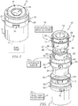
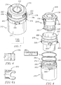
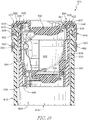
- a first fuel tank filler apparatus 10 in accordance with the present invention includes a fuel-tank filler neck 12 associated with a fuel tank 11, a capless filler neck closure 14, and an interface sleeve 16 as shown in Figs. 1-3 .
- Interface sleeve 16 is shaped to push a portion of filler neck 12 into a round shape where closure 14 is inserted into filler neck 12 to facilitate sealing between filler neck 12 and closure 14.
- Interface sleeve 16 is adapted to couple closure 14 to filler neck 12 such that closure 14 is removable from filler neck 12 for service or replacement.
- Closure 14 is not welded permanently to filler neck 12 when coupled to filler neck 12 by interface sleeve 16 and is removable by service technicians for service.
- Interface sleeve 16 includes crimp tabs 20 configured to engage filler neck 12 and a catch receivers 22 adapted to be engaged by catches 38 included in closure 14 in order to interconnect filler neck 12 and closure 14.
- a technician would uncramp crimp tabs 20 of interface sleeve 16 such that crimp tabs 20 are disengaged from filler neck 12 before lifting closure 14 and interface sleeve 16 out of filler neck 12. The technician could then service closure 14 outside of filler neck 12.
- the technician may replace interface sleeve 16 as part of servicing closure 14 or may leave interface sleeve 16 in place during service.
- the technician could reinsert closure 14 and interface sleeve 16 into filler neck 12 and deform crimp tabs 20 to re-couple closure 14 to filler neck 12.
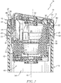
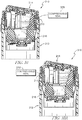
- capless filler neck closure 14 is adapted to close filler neck 12 to block fuel and fuel vapor from escaping fuel tank 11 through filler neck 12 when fuel tank 11 is not being refueled as suggested in Fig. 1 .
- Closure 14 illustratively includes a nozzle-insertion housing 30 that is sized to extend into fuel-tank filler neck 12, an outer dust cover 32 mounted to housing 30, and an inner closure door 34 mounted to housing 30.
- Nozzle-insertion housing 30 forms a nozzle-insertion passageway 35 sized to receive a fuel-dispensing nozzle that extends through passageway 35 into filler neck 12 during refueling.
- Outer dust cover 32 and inner closure door 34 are mounted to pivot relative housing 30 when a fuel-dispensing nozzle is inserted into closure 14 for refueling.
- Nozzle-insertion housing 30 of capless filler neck closure 14 is illustratively formed from polymeric materials and may be a multi-component assembly as shown in Fig. 3 .
- Housing 30 of the exemplary embodiment includes an outer side wall 36 and catches 38 that extend outward in a radial direction from outer side wall 36 away from a central axis 15 of fuel tank filler apparatus 10.
- Seals 41, 42 are received in grooves formed in outer side wall 36 and engage interface sleeve 16 to seal between closure 14 and interface sleeve 16.
- Catches 38 engage catch receivers 22 of interface sleeve 16 to couple closure 14 to interface sleeve 16.
- Catches 38 are deformable and are angled to bend during insertion of closure 14 into interface sleeve 16.
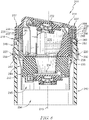
- Interface sleeve 16 illustratively is a monolithic, one-piece component that comprises metallic materials (i.e. stainless steel) as suggested in Figs. 1-3 .
- Interface sleeve 16 is formed to include an inner wall 44 that defines a closure-receiving space 45, an outer wall 46, and a top wall 48 as shown in Fig. 3 .
- Inner wall 44 extends inside filler neck 12 along axis 15 and is formed to include catch receivers 22 that are engaged by catches 38 of closure 14.
- Outer wall 46 extends outside filler neck 12 along axis 15 and is formed to include crimp tabs 20.
- Top wall 48 interconnects inner wall 44 and outer wall 46 to define a downwardly opening channel 47 that receives a portion of filler neck 12.
- Filler neck 12 is illustratively a blow-molded tube having a roughly 60 millimeter diameter and is adapted to be coupled to fuel tank 11 as suggested in Fig. 1 .
- Filler neck 12 is formed to include tab receivers 50 and a seal groove 52 as shown in Fig. 2 .
- Tab receivers 50 are spaced circumferentially around filler neck 12 and extend radially inward into filler neck 12.
- Tab receivers 50 receive crimp tabs 20 of interface sleeve 16 when they are deformed to couple interface sleeve 16 to filler neck 12.
- O-ring seal 60 included in fuel tank filler apparatus 10 seals between filler neck 12 and interface sleeve 16 as shown in Fig. 3 .
- O-ring seal 60 is sized to be received in groove 52 formed in filler neck 12.
- Inner wall 44 is shaped to push a portion of filler neck 12 into a round shape in a location where closure 14 is inserted into filler neck 12 as suggested in Fig. 3 .
- inner wall 44 controls the roundness of filler neck 12 for sealing between closure 14 and filler neck 12 by seals 41, 42.
- inner wall 44 and closure 14 are rigid such that a gap formed between inner wall 44 and closure 14 is uniform around closure 14.
- seals 41, 42 may be selected to have a desired uniform size to properly seal the uniform gap formed between inner wall 44 and closure 14.
- pushing filler neck 12 into round causes a gap formed between outer wall 46 and filler neck 12 to be uniform around filler neck 12.
- seal 60 may be selected to have a desired uniform size to properly seal the uniform gap formed between outer wall 46 and filler neck 12.
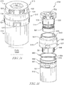
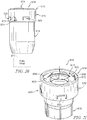
- a second fuel tank filler apparatus 210 in accordance with the present invention includes a fuel-tank filler neck 212 associated with a fuel tank 211, a capless filler neck closure 214, and an interface sleeve 216 as shown in Figs. 4-6 .
- Interface sleeve 216 is adapted to couple closure 214 to filler neck 212 such that closure 214 is removable from filler neck 212 for service or replacement.
- Interface sleeve 216 includes crimp tabs 220 configured to engage filler neck 212 and a catch receivers 222 adapted to be engaged by catches 238 included in closure 214 in order to interconnect filler neck 212 and closure 214.
- Closure 214 is not welded permanently to filler neck 212 when coupled to filler neck 212 by interface sleeve 216 and is removable by service technicians for service.
- Capless filler neck closure 214 is adapted to close filler neck 212 to block fuel and fuel vapor from escaping fuel tank 211 through filler neck 212 when fuel tank 211 is not being refueled as suggested in Fig. 4 .
- Closure 214 illustratively includes a nozzle-insertion housing 230 that is sized to extend into fuel-tank filler neck 212, an outer dust cover 232 mounted to housing 230, and an inner closure door 234 mounted to housing 230.
- Nozzle-insertion housing 230 forms a nozzle-insertion passageway 235 sized to receive a fuel-dispensing nozzle that extends through passageway 235 into filler neck 212 during refueling.
- Outer dust cover 232 and inner closure door 234 are mounted to pivot relative housing 230 when a fuel-dispensing nozzle is inserted into closure 214 for refueling.
- Nozzle-insertion housing 230 of capless filler neck closure 214 is illustratively formed from polymeric materials and may be a multi-component assembly as shown in Fig. 6 .
- Housing 230 of the exemplary embodiment includes an outer side wall 236, a rim 237 that extends around outer side wall 236, and catches 238 that extend inward in a radial direction from rim 237 toward a central axis 215 of fuel tank filler apparatus 210.
- Seals 241, 242 are received in grooves formed in outer side wall 236 and engage interface sleeve 216 to seal between closure 214 and interface sleeve 216.
- Catches 238 engage catch receivers 222 of interface sleeve 216 to couple closure 214 to interface sleeve 216.
- Catches 238 are plastically deformable in some embodiments, in other embodiments, catches 238 are elastically deformable.
- Interface sleeve 216 illustratively is a monolithic, one-piece component that comprises metallic materials(i.e. stainless steel) as suggested in Figs. 4-6 .
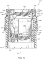
- Interface sleeve 216 is formed to include an inner wall 244 that defines a closure-receiving space 245, an outer wall 246, and a top wall 248 as shown in Fig. 6 .
- Inner wall 244 extends inside filler neck 212 along axis 215.
- Outer wall 246 extends outside filler neck 212 along axis 215 and is formed to include crimp tabs 220.
- Top wall 248 interconnects inner wall 244 and outer wall 246 to define a downwardly opening channel 247 that receives a portion of filler neck 212.
- Top wall 248 is further formed to include catch receivers 222 that are engaged by catches 238 of closure 214.
- Filler neck 212 is illustratively a blow-molded tube having a roughly 60 millimeter diameter and is adapted to be coupled to fuel tank 211 as suggested in Fig. 4 .
- Filler neck 212 is formed to include tab receivers 250 and a seal groove 252 as shown in Fig. 5 .
- Tab receivers 250 are spaced circumferentially around filler neck 212 and extend radially inward into filler neck 212.
- Tab receivers 250 receive crimp tabs 220 of interface sleeve 216 when they are deformed to couple interface sleeve 216 to filler neck 212.
- O-ring seal 260 included in fuel tank filler apparatus 210 seals between filler neck 212 and interface sleeve 216 as shown in Fig. 6 .
- O-ring seal 260 is sized to be received in groove 252 formed in filler neck 212.
- a third fuel tank filler apparatus 310 in accordance with the present disclosure includes a fuel-tank filler neck 212 associated with a fuel tank 211, a capless filler neck closure 214, and an interface sleeve 216 as shown in Figs. 7-10 .
- Fuel tank filler apparatus 310 is substantially similar to fuel tank filler apparatus 210 described above as suggested by similar reference numbers in the 200 series.
- Fuel tank filler apparatus 310 is unlike fuel tank filler apparatus 210 in that fuel tank filler apparatus 310 includes a compression seal 370 arranged along a top surface 213 of filler neck 212 to seal between filler neck 212 and interface sleeve 216 as shown in Figs. 8 and 10 .
- Compressible seal 370 is illustratively arranged between top surface 213 of filler neck 212 and top wall 248 of interface sleeve 216.
- compressible seal 370 is annular and has an H-shaped cross section as shown in Fig. 9 and 10 .
- Compressible seal 370 may also be hollow.
- compressible seal 370' is annular and has a C-shaped cross section as shown in Figs. 9A and 10A .
- Fuel tank filler apparatus 410 in accordance with the present invention is shown in Figs. 11-13 .
- Fuel tank filler apparatus 410 is similar to fuel tank filler apparatus 210 but is reconfigured for inclusion of a 48 millimeter filler neck 412 rather than a 60 millimeter filler neck (i.e. filler neck 212).
- Fuel tank filler apparatus 410 illustratively includes a fuel-tank filler neck 412 associated with a fuel tank 411, a capless filler neck closure 414, and an interface sleeve 416 as shown in Figs. 11-13 .
- Interface sleeve 416 is adapted to couple closure 414 to filler neck 412 such that closure 414 is removable from filler neck 412 for service or replacement.
- Interface sleeve 416 includes crimp tabs 420 configured to engage filler neck 412 and a catch receivers 422 adapted to be engaged by catches 438 included in closure 414 in order to interconnect filler neck 412 and closure 414.
- Closure 414 is not welded permanently to filler neck 412 when coupled to filler neck 412 by interface sleeve 416 and is removable by service technicians for service.
- Capless filler neck closure 414 is adapted to close filler neck 412 to block fuel and fuel vapor from escaping fuel tank 411 through filler neck 412 when fuel tank 411 is not being refueled as suggested in Fig. 11 .
- Closure 414 illustratively includes a nozzle-insertion housing 430 that is sized to extend into fuel-tank filler neck 412, an outer dust cover 432 mounted to housing 430, and an inner closure door 434 mounted to housing 430.
- Nozzle-insertion housing 430 forms a nozzle-insertion passageway 435 sized to receive a fuel-dispensing nozzle that extends through passageway 435 into filler neck 412 during refueling.
- Outer dust cover 432 and inner closure door 434 are mounted to pivot relative housing 430 when a fuel-dispensing nozzle is inserted into closure 414 for refueling.
- Nozzle-insertion housing 430 of capless filler neck closure 414 is illustratively formed from polymeric materials and may be a multi-component assembly as shown in Fig. 13 .
- Housing 430 of the exemplary embodiment includes an outer side wall 436, a rim 437 that extends around outer side wall 436, and catches 438 that extend inward in a radial direction from rim 437 toward a central axis 415 of fuel tank filler apparatus 410.
- Seals 441, 442 are received in grooves formed in outer side wall 436 and engage interface sleeve 416 to seal between closure 414 and interface sleeve 416.
- Catches 438 engage catch receivers 422 of interface sleeve 416 to couple closure 414 to interface sleeve 416.
- Catches 438 are plastically deformable in the illustrative embodiment.
- Interface sleeve 416 illustratively is a monolithic, one-piece component that comprises metallic materials (i.e. stainless steel) as suggested in Figs. 11-13 .
- Interface sleeve 416 is formed to include an inner wall 444 that defines a closure-receiving space 445, an outer wall 446, and a top wall 448 as shown in Fig. 13 .
- Inner wall 444 extends inside filler neck 412 along axis 415.
- Outer wall 446 extends outside filler neck 412 along axis 415 and is formed to include crimp tabs 420.
- Top wall 448 interconnects inner wall 444 and outer wall 446 to define a downwardly opening channel 447 that receives a portion of filler neck 412.
- Top wall 448 is further formed to include catch receivers 422 that are engaged by catches 438 of closure 414.
- Filler neck 412 is illustratively a blow-molded tube having a roughly 48 millimeter diameter and is adapted to be coupled to fuel tank 411 as suggested in Fig. 11 .
- Filler neck 412 is formed to include tab receivers 450 and a seal groove 452 as shown in Fig. 12 .
- Tab receivers 450 are spaced circumferentially around filler neck 412 and extend radially inward into filler neck 412.
- Tab receivers 450 receive crimp tabs 420 of interface sleeve 416 when they are deformed to couple interface sleeve 416 to filler neck 412.
- O-ring seal 460 included in fuel tank filler apparatus 410 seals between filler neck 412 and interface sleeve 416 as shown in Fig. 13 .
- O-ring seal 460 is sized to be received in groove 452 formed in filler neck 412.
- Fuel tank filler apparatus 510 is similar to fuel tank filler apparatus 410 including a 48 millimeter filler neck 512 rather than a 60 millimeter filler neck (i.e. filler neck 212). However, fuel tank filler apparatus 510 includes an interface sleeve 516 comprising polymeric materials (i.e. plastics) and having catches 521 rather than crimp tabs (i.e. crimp tabs 220).
- interface sleeve 516 comprising polymeric materials (i.e. plastics) and having catches 521 rather than crimp tabs (i.e. crimp tabs 220).
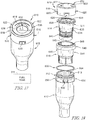
- Fuel tank filler apparatus 510 illustratively includes a fuel-tank filler neck 512 associated with a fuel tank 511, a capless filler neck closure 514, and interface sleeve 516 as shown in Figs. 14-16 .
- Interface sleeve 516 is adapted to couple closure 514 to filler neck 512 such that closure 514 is removable from filler neck 512 for service or replacement.
- Interface sleeve 516 includes catchtes 521 configured to engage filler neck 512 and a catch receivers 522 adapted to be engaged by catches 538 included in closure 514 in order to interconnect filler neck 512 and closure 514.
- Closure 514 is not welded permanently to filler neck 512 when coupled to filler neck 512 by interface sleeve 516 and is removable by service technicians for service.
- Capless filler neck closure 514 is adapted to close filler neck 512 to block fuel and fuel vapor from escaping fuel tank 511 through filler neck 512 when fuel tank 511 is not being refueled as suggested in Fig. 11 .
- Closure 514 illustratively includes a nozzle-insertion housing 530 that is sized to extend into fuel-tank filler neck 512, an outer dust cover 532 mounted to housing 530, and an inner closure door 534 mounted to housing 530.
- Nozzle-insertion housing 530 forms a nozzle-insertion passageway 535 sized to receive a fuel-dispensing nozzle that extends through passageway 535 into filler neck 512 during refueling.
- Outer dust cover 532 and inner closure door 534 are mounted to pivot relative housing 530 when a fuel-dispensing nozzle is inserted into closure 514 for refueling.
- Nozzle-insertion housing 530 of capless filler neck closure 514 is illustratively formed from polymeric materials (i.e. plastics) and may be a multi-component assembly as shown in Fig. 16 .
- Housing 530 of the exemplary embodiment includes an outer side wall 536, a rim 537 that extends around outer side wall 536, and catches 538 that extend inward in a radial direction from rim 537 toward a central axis 515 of fuel tank filler apparatus 510.
- Seals 541, 542 are received in grooves formed in outer side wall 536 and engage interface sleeve 516 to seal between closure 514 and interface sleeve 516.
- Catches 538 engage catch receivers 522 of interface sleeve 516 to couple closure 514 to interface sleeve 516.
- Catches 538 are plastically deformable in the illustrative embodiment.
- Top wall 548 interconnects inner wall 544 and outer wall 546 to define a downwardly opening channel 547 that receives a portion of filler neck 512.
- Top wall 548 is further formed to include catch receivers 522 that are engaged by catches 538 of closure 514.
- Filler neck 512 is illustratively a blow-molded tube having a roughly 48 millimeter diameter and is adapted to be coupled to fuel tank 511 as suggested in Fig. 14 .
- Filler neck 512 is formed to include catch receivers 551 and a seal groove 552 as shown in Fig. 12 .
- Catch receivers 551 are spaced circumferentially around filler neck 512 and extend radially inward into filler neck 512.
- Catch receivers 551 receive catches 521 of interface sleeve 516.
- O-ring seal 560 included in fuel tank filler apparatus 510 seals between filler neck 512 and interface sleeve 516 as shown in Fig. 13 .
- O-ring seal 560 is sized to be received in groove 552 formed in filler neck 512.
- Another fuel tank filler apparatus 610 in accordance with the present invention includes a fuel-tank filler neck 612 associated with a fuel tank 611, a capless filler neck closure 614, an interface sleeve 616, and a retainer ring 618 as shown in Figs. 17-21 .
- Interface sleeve 616 is shaped to push fuel-tank filler neck 612 into a round shape and, along with capless filler neck closure 614, seals fuel-tank filler neck 612 from atmosphere.
- Retainer ring 618 couples closure 614 to filler neck 612 such that closure 614 is removable from filler neck 612 for service or replacement.
- Retainer ring 618 includes crimp tabs 620 configured to engage filler neck 612 and cam tabs 622 that are received in cam slots 638 formed by closure 614 to couple retainer ring 618 to closure 614.
- Closure 614 is not welded permanently to filler neck 612 when coupled to filler neck 612 by retainer ring 618 and is removable by service technicians for service.
- a technician would uncramp crimp tabs 620 of retainer ring 618 such that crimp tabs 620 are disengaged from filler neck 612 before lifting closure 614 and interface sleeve 616 out of filler neck 612.
- the technician could then service closure 614 outside of filler neck 612.
- the technician may replace retainer ring 618 as part of servicing closure 614 or may reuse retainer ring 618.
- the technician could attach/reattach retainer ring 618 to closure 614, reinsert closure 614 and interface sleeve 616 into filler neck 612, and deform crimp tabs 620 to re-couple closure 614 to filler neck 12.
- capless filler neck closure 614 is adapted to close filler neck 612 to block fuel and fuel vapor from escaping fuel tank 611 through filler neck 612 when fuel tank 611 is not being refueled as suggested in Fig. 17 .
- Closure 614 illustratively includes a nozzle-insertion housing 630 that is sized to extend into fuel-tank filler neck 612, an outer dust cover 632 mounted to housing 630, and an inner closure door 634 mounted to housing 630.
- Nozzle-insertion housing 630 forms a nozzle-insertion passageway 635 sized to receive a fuel-dispensing nozzle that extends through passageway 635 into filler neck 612 during refueling.
- Outer dust cover 632 and inner closure door 634 are mounted to pivot relative housing 630 when a fuel-dispensing nozzle is inserted into closure 614 for refueling.
- Nozzle-insertion housing 630 of capless filler neck closure 614 is illustratively formed from polymeric materials and may be a multi-component assembly as shown in Fig. 19 .
- Housing 630 of the exemplary embodiment includes an outer side wall 636.
- Seals 641, 642 are received in grooves formed in outer side wall 636 and engage interface sleeve 616 to seal between and couple via interference fit closure 614 and interface sleeve 616.
- Interface sleeve 616 illustratively is a monolithic, one-piece component that comprises polymeric materials (i.e. plastics such as PA66 Zytel) as suggested in Figs. 17-19 .
- Interface sleeve 616 is formed to include an inner wall 644 that defines a closure-receiving space 645, an outer wall 646, and a top wall 648 as shown in Fig. 19 .
- Inner wall 644 extends inside filler neck 612 along axis 615 of apparatus 610.
- Outer wall 646 extends outside filler neck 612 along axis 615.
- Top wall 648 interconnects inner wall 644 and outer wall 646 to define a downwardly opening channel 647 that receives an end portion of filler neck 612.
- Retainer ring 618 is coupled to closure 614 and engages filler neck 612 to mount closure 614 (and interface sleeve 616) to filler neck 612 as shown in Figs. 17 and 19 .
- Retainer ring 618 includes an outer band 670, crimp tabs 620, a cap wall 672, and cam tabs 622.
- Outer band 670 extends around closure 614 and along axis 615 and is formed to include side slots 674 that receive guide pegs 675 included in filler neck 612 to orient and anti-rotate retainer ring 618 and closure 614 relative to filler neck 612.
- Crimp tabs 620 are configured to be bent out of alignment with outer band 670 into tab receivers 650 formed in filler neck 612 to couple retainer ring 618 and closure 614 to filler neck 612.
- Cap wall 672 extends radially inwardly from outer band 670 toward axis 615 over a portion of closure 614.
- Cam tabs 622 extend radially inwardly from cap wall 672 and are received in cam slots 638 formed by closure 614 to couple retainer ring 618 to closure 614.
- Retainer ring 618 illustratively comprises metallic materials (i.e. stainless steel 304L) but may be made from other suitable materials as well.
- Filler neck 612 is illustratively a blow-molded tube having a roughly 648 millimeter diameter and is adapted to be coupled to fuel tank 611 as suggested in Fig. 17 .
- Filler neck 612 is formed to include tab receivers 650 and a seal groove 652 as shown in Fig. 18 .
- Tab receivers 650 are spaced circumferentially around filler neck 612 and extend radially inward into filler neck 612.
- Tab receivers 650 receive crimp tabs 620 of interface sleeve 616 when they are deformed to couple interface sleeve 616 to filler neck 612.
- O-ring seal 660 included in fuel tank filler apparatus 610 seals between filler neck 612 and interface sleeve 616 as shown in Fig. 19 .
- O-ring seal 660 is sized to be received in groove 652 formed in filler neck 612.
- Embodiments of the present invention provide a low permeation connection of capless unit/closure with blow molded multilayer plastic filler pipe/neck.
- the coupling of the capless unit and the plastic filler pipe is illustratively accomplished by: inserting the capless unit into a plastic sleeve creating an internal seal between these units; assembling a metal cover to this capless sub assembly with a cam-lock to provide ease of assembly and serviceability; assembling an (1) or (2) o-rings in o-ring groves on the outside diameter of the plastic filler pipe; inserting the entire capless sub-assembly with in an axial direction, where features on the metal ring are crimped into indentations on the outside diameter of the pipe to provide attachment.
- fuel tank filler apparatus 10 includes fuel-tank filler neck 12 associated with fuel tank 11, capless filler neck closure 14, and interface means 16 for coupling capless filler neck closure 14 to fuel-tank filler neck 12 without welds or permanent attachment to block relative axial movement between capless filler neck closure 14 and fuel-tank filler neck 12 and for blocking fuel and fuel vapor from escaping between capless filler neck closure 14 and fuel-tank filler neck 12 during use of fuel tank filler apparatus 10 while allowing capless filler neck closure 14 to be removable selectively from fuel-tank filler neck 12 for service and replacement.
- interface means 16 includes interface sleeve 16.
- fuel-tank filler neck 12 comprises plastic material.
- Interface sleeve 16 comprises metallic material and extends into fuel-tank filler neck 12 to push fuel-tank filler neck 12 into a round shape.
- fuel-tank filler neck 12 may be formed by a blow molding process which is relatively inexpensive as compared to other filler necks such as, for example, filler necks comprising metallic material.
- Interface sleeve 16 is rigid compared to fuel-tank filler neck 12 and relatively inexpensive to manufacture.
- interface sleeve 16 may be used to push fuel-tank filler neck 12 into a round shape and couple capless filler neck closure 14 to fuel-tank filler neck 12 while being sacrificial to allow capless filler neck closure 14 to be separated from fuel-tank filler neck 12 and interface sleeve 16 for repair and/or replacement.
- Fuel-tank filler neck 12 is arranged to extend around central axis 15 of fuel tank filler apparatus 10 to define a fuel receiving passageway 54 as shown in Fig. 2 .
- Fuel-tank filler neck 12 includes an outer end having a top surface 13 arranged to define a mouth that opens into fuel receiving passageway 54.
- Filler neck 12 is illustratively a blow-molded tube having a roughly sixty millimeter diameter and is adapted to be coupled to fuel tank 11 as suggested in Fig. 1 .
- Filler neck 12 is formed to include tab receivers 50 and a seal groove 52 as shown in Fig. 2 .
- Tab receivers 50 are spaced circumferentially around filler neck 12 and extend radially inward into filler neck 12.
- Tab receivers 50 receive crimp tabs 20 of interface sleeve 16 when they are deformed to couple interface sleeve 16 to filler neck 12.
- tab receivers 50 extend radially inward toward central axis 15 into filler neck 12 to form one or more indentations into filler neck 12.
- O-ring seal 60 included in fuel-tank filler neck apparatus 10 seals between filler neck 12 and interface sleeve 16 as shown in Fig. 3 .
- O-ring seal 60 is sized to be received in groove 52 formed in filler neck 12. Seal 60 is located axially between top surface 13 and tab receivers 50.
- Capless filler neck closure 14 is adapted to extend into and be mated with the outer end of fuel-tank filler neck 12 to block fuel and fuel vapor from escaping fuel-tank filler neck 12 during use of fuel tank filler apparatus 10.
- Capless filler neck closure 14 includes nozzle-insertion housing 30 arranged to extend into fuel receiving passageway 54 of fuel-tank filler neck 12, outer dust cover 32 pivotably mounted to nozzle-insertion housing 30, and inner closure door 34 spaced apart axially from outer dust cover 32 and pivotably mounted to nozzle-insertion housing 30.
- outer dust cover 32 is angled relative to central axis 15.
- Nozzle-insertion housing 30 includes an outer side wall 36, a rim 37, and one or more catches 38 as shown in Figs. 2 and 3 .
- Outer side wall 36 is arranged around central axis 15 to define nozzle-insertion passageway 35.
- Rim 37 extends radially outward away from outer side wall 36 toward interface sleeve 16.
- rim 37 engages top wall 48 of interface sleeve 16 to block access into closure-receiving space 45.
- One or more catches 38 are spaced axially apart from rim 37 and extend radially outward away from outer side wall 36 into one or more catch receivers 22, respectively, formed in interface sleeve 16.
- One or more catches 38 are deformable and form one or more flanges that may be elastically deformed radially inward in response to nozzle-insertion housing 30 being inserted into closure-receiving space 45. Catches 38 move toward their non-deformed state and extend into catch receivers 22 in response to nozzle-insertion housing 30 being assembled with interface sleeve 16 in its proper position.
- Nozzle-insertion housing 30 of capless filler neck closure 14 is illustratively formed from polymeric materials and may be a multi-component assembly as shown in Fig. 3 .
- Seals 41, 42 are received in grooves formed in outer side wall 36 and engage interface sleeve 16 to seal between closure 14 and interface sleeve 16. Seal 41 is located below and engages catch 38. Seal 42 is spaced apart axially from catch 38 to locate axially seal 41 therebetween.
- Catches 38 engage catch receivers 22 of interface sleeve 16 to couple closure 14 to interface sleeve 16. Catches 38 are deformable and are angled to bend during insertion of closure 14 into interface sleeve 16.
- Interface sleeve 16 is adapted to couple closure 14 to filler neck 12 such that closure 14 is removable from filler neck 12 for service or replacement.
- Interface sleeve 16 illustratively is a monolithic, one-piece component that comprises metallic materials (i.e. stainless steel) as suggested in Figs. 1-3 .
- Interface sleeve 16 includes inner wall 44 that defines closure-receiving space 45 adapted to receive nozzle-insertion housing 30 and outer wall 46 that is spaced apart radially from inner wall 44 as shown in Fig. 3 .
- Inner wall 44 is formed to include one or more catch receivers 22 adapted to receive deformable catch 38 to couple capless filler neck closure 14 to interface sleeve 16.
- Catch receiver 22 extends radially outward away from central axis 15 into interface sleeve 16 to form an indention into interface sleeve 16.
- Outer wall 46 is formed to include one or more crimp tab 20 adapted to extend into a tab receiver 50 and engage fuel-tank filler neck 12 to couple interface sleeve 16 to fuel-tank filler neck 12.
- Crimp tabs 20 are configured to be plastically deformed radially inward into tab receivers 50. To separate interface sleeve 16 from fuel-tank filler neck 12, crimp tabs 20 are plastically deformed radially outward away from and out of tab receivers 50. Crimp tabs 20 may be plastically deformed radially inward or outward using a tool such as, for example, pliers, clamps, screwdrivers, etc.
- Interface sleeve 16 further includes top wall 48 which interconnects inner wall 44 and outer wall 46 to define a downwardly opening channel 47 that receives outer end of filler neck 12.
- Top wall 48 is located axially between and illustratively engaged with rim 37 and top surface 13.
- Closure 14 is not welded permanently to filler neck 12 when coupled to filler neck 12 by interface sleeve 16 and is removable by service technicians for service.
- a technician would uncramp crimp tabs 20 of interface sleeve 16 such that crimp tabs 20 are disengaged from filler neck 12 before lifting closure 14 and interface sleeve 16 out of filler neck 12.
- the technician could then service closure 14 outside of filler neck 12.
- the technician may replace interface sleeve 16 as part of servicing closure 14 or may leave interface sleeve 16 in place during service.
- the technician could reinsert closure 14 and interface sleeve 16 into filler neck 12 and deform crimp tabs 20 to re-couple closure 14 to filler neck 12.
- fuel tank filler apparatuses 210, 310 include fuel-tank filler neck 212 associated with fuel tank 211, capless filler neck closure 214, and interface means 216 for coupling capless filler neck closure 214 to fuel-tank filler neck 212 without welds or permanent attachment to block relative axial movement between capless filler neck closure 214 and fuel-tank filler neck 212 and for blocking fuel and fuel vapor from escaping between capless filler neck closure 214 and fuel-tank filler neck 212 during use of fuel tank filler apparatus 210 while allowing capless filler neck closure 214 to be removable selectively from fuel-tank filler neck 212 for service and replacement.
- interface means 216 includes interface sleeve 216.
- Capless filler neck closure 214 of fuel tank filler apparatus 210 includes nozzle-insertion housing 230, outer dust cover 232, and inner closure door 234 as shown in Figs. 6 and 10 .
- Nozzle-insertion housing 230 includes outer side wall 236, rim 237 that extends radially outward away from outer side wall 236, an outer band 239 that is radially spaced apart from outer side wall 236 and that is arranged to extend axially downwardly away from rim 237, and catches 238 that extend radially inwardly away from outer band 239 toward central axis 15 and into catch receivers 222 formed in interface sleeve 216.
- Rim 237 is arranged to contact a first portion of top wall 248 of interface sleeve 216 to block access into nozzle-insertion passageway 235.
- Outer band 239 extends around interface sleeve 216 and extends toward a second portion of top wall 248 as shown in Fig. 6 .
- Outer band 239 and catches 238 are configured to deformed elastically.
- Interface sleeve 216 is adapted to couple closure 214 to filler neck 212 such that closure 214 is removable from filler neck 212 for service or replacement as suggested in Figs. 6 and 10 .
- Interface sleeve 216 illustratively is a monolithic, one-piece component that comprises metallic materials (i.e. stainless steel).
- Interface sleeve 216 includes inner wall 244 that defines closure-receiving space 245 adapted to receive nozzle-insertion housing 230, outer wall 246 that is spaced apart radially from inner wall 244, and top wall 248 as shown in Fig. 6 .
- Top wall 248 interconnects inner wall 244 and outer wall 246.
- Top wall 248 is formed to include one or more catch receivers 222 adapted to receive deformable catches 238 to couple capless filler neck closure 214 to interface sleeve 216.
- Top wall 248 includes an upwardly facing surface 256, a downwardly facing surface 258 spaced apart axially from upwardly facing surface 256, and a radially outwardly facing surface 262 interconnecting upwardly facing surface 256 and downwardly facing surface 258 to define catch receivers 222.
- surfaces 256, 258, 262 extend around central axis 215 to form an annular catch receiver 222 configured to receive one or more catches 238.
- interface sleeve 216 are formed from a single piece of sheet metal that is shaped to provide inner wall 244, outer wall 246, and top wall 248. The sheet metal is folded over itself to form top wall 248.
- fuel tank filler apparatus 310 includes a compressible seal 370.
- Compressible seal 370 is located axially between fuel-tank filler neck 212 and top wall 248 of interface sleeve 216.
- fuel tank filler apparatus 410 includes fuel-tank filler neck 412 associated with fuel tank 411, capless filler neck closure 414, and interface means 416 for coupling capless filler neck closure 414 to fuel-tank filler neck 412 without welds or permanent attachment to block relative axial movement between capless filler neck closure 414 and fuel-tank filler neck 412 and for blocking fuel and fuel vapor from escaping between capless filler neck closure 414 and fuel-tank filler neck 412 during use of fuel tank filler apparatus 410 while allowing capless filler neck closure 414 to be removable selectively from fuel-tank filler neck 412 for service and replacement.
- interface means 416 includes interface sleeve 416.
- Capless filler neck closure 414 is formed with a planar outer end as shown in Fig. 13 . As such, rim 437 defines an upper most portion of capless filler neck closure 414. Outer dust cover 432 and inner closure door 434 extend generally perpendicular to central axis 415.
- fuel tank filler apparatus 510 includes fuel-tank filler neck 512 associated with fuel tank 511, capless filler neck closure 514, and interface means 516 for coupling capless filler neck closure 514 to fuel-tank filler neck 512 without welds or permanent attachment to block relative axial movement between capless filler neck closure 514 and fuel-tank filler neck 512 and for blocking fuel and fuel vapor from escaping between capless filler neck closure 514 and fuel-tank filler neck 512 during use of fuel tank filler apparatus 510 while allowing capless filler neck closure 514 to be removable selectively from fuel-tank filler neck 512 for service and replacement.
- interface means 516 includes interface sleeve 516.
- Capless filler neck closure 514 is formed with a planar outer end as shown in Fig. 16 . As such, rim 537 defines an upper most portion of capless filler neck closure 514. Outer dust cover 532 and inner closure door 534 extend generally perpendicular to central axis 515. Interface sleeve 516 illustratively comprises plastic material as suggested in Fig. 16 .
- fuel tank filler apparatus 610 includes fuel-tank filler neck 612 associated with fuel tank 611, capless filler neck closure 614, and interface means for coupling capless filler neck closure 614 to fuel-tank filler neck 612 without welds or permanent attachment to block relative axial movement between capless filler neck closure 614 and fuel-tank filler neck 612 and for blocking fuel and fuel vapor from escaping between capless filler neck closure 614 and fuel-tank filler neck 612 during use of fuel tank filler apparatus 610 while allowing capless filler neck closure 614 to be removable selectively from fuel-tank filler neck 612 for service and replacement.
- interface means includes retainer ring 618 and interface sleeve 616.
- Retainer ring 618 includes an outer band 670, a cap wall 672, and one orm ore crimp tabs 620.
- Outer band 670 is arranged to extend circumferentially around fuel-tank filler neck 612.
- Cap wall 672 extends radially inwardly away from outer band 670 toward central axis 615 into cam slot 638 formed in capless filler neck closure 614 to couple retainer ring 618 to capless filler neck closure 614.
- Crimp tab 620 is configured to extend into tab receiver 650 included in fuel-tank filler neck 612 to couple retainer ring 618 to fuel-tank filler neck 612.
- retainer ring 618 further includes one or more cam tabs 622 that extend radially inwardly from cap wall 672 and cam tabs 622 extend into cam slot 638.
Landscapes
- Engineering & Computer Science (AREA)
- Mechanical Engineering (AREA)
- Life Sciences & Earth Sciences (AREA)
- Sustainable Development (AREA)
- Sustainable Energy (AREA)
- Chemical & Material Sciences (AREA)
- Combustion & Propulsion (AREA)
- Transportation (AREA)
- Cooling, Air Intake And Gas Exhaust, And Fuel Tank Arrangements In Propulsion Units (AREA)
Claims (13)
- Kraftstofftank-Füllvorrichtung (10), die zur Verwendung in einem Fahrzeugkraftstoffsystem eingerichtet ist, wobei die Kraftstofftank-Füllvorrichtung (10) aufweisteinen blasgeformten Kraftstofftank-Einfüllstutzen (12), der einem Kraftstofftank (11) zugeordnet ist, wobei der blasgeformte Kraftstofftank-Einfüllstutzen (12) geformt ist, um sich um eine Mittelachse der Kraftstofftank-Füllvorrichtung (10) zu erstrecken, um einen kraftstoffaufnehmenden Durchgang (54) zu definieren, und der blasgeformte Kraftstofftank-Einfüllstutzen (12) ein äußeres Ende mit einer oberen Oberfläche aufweist, die eine Öffnung definiert, die sich in den kraftstoffaufnehmenden Durchgang (54) erstreckt,einen deckellosen Einfüllstutzen-Verschluss (14), der eingerichtet ist, um mit dem äußeren Ende des blasgeformten Kraftstofftank-Einfüllstutzens (12) zusammengefügt zu werden, um zu verhindern, dass Kraftstoff und Kraftstoffdampf während der Verwendung der Kraftstofftank-Füllvorrichtung (10) aus dem blasgeformten Kraftstofftank-Einfüllstutzen (12) entweichen, wobei der deckellose Einfüllstutzen-Verschluss (14) ein Düseneinführgehäuse (30), das sich in den blasgeformten Kraftstofftank-Einfüllstutzen (12) erstreckt, eine äußere Staubschutzabdeckung (32), die montiert ist, um relativ zu dem Düseneinführgehäuse (30) von einer geschlossenen Position, die angeordnet ist, um zu verhindern, dass Staub in den Düseneinführdurchgang (35) gelangt, in eine offene Position zu schwenken, die angeordnet ist, um zu erlauben, dass eine Kraftstoffdüse in den Düseneinführdurchgang (35) gelangt, und eine innere Verschlusstür (34) aufweist, die von der äußeren Staubschutzabdeckung (32) entlang der Mittelachse (15) beabstandet ist und montiert ist, um relativ zu dem Düseneinführgehäuse (30) von einer geschlossenen Position, die angeordnet ist, um zu verhindern, dass Kraftstoff und Kraftstoffdampf aus dem zugeordneten Kraftstofftank (11) entweichen, in eine offene Position zu schwenken, die angeordnet ist, um zu erlauben, dass eine Kraftstoffdüse in den kraftstoffaufnehmenden Durchgang (54) gelangt, undein Schnittstellenmittel, um einen Teil des blasgeformten Kraftstofftank-Einfüllstutzens (12) in eine runde Form zu drücken, um die Aufnahme des deckellosen Einfüllstutzen-Verschlusses (14) in den blasgeformten Kraftstofftank-Einfüllstutzen (12) zu erleichtern, und um den deckellosen Einfüllstutzen-Verschluss (14) ohne Schweißnähte oder dauerhafte Befestigung an den blasgeformten Kraftstofftank-Einfüllstutzen (12) zu koppeln, um das selektive Entkoppeln des deckellosen Einfüllstutzen-Verschlusses (14) von dem blasgeformten Kraftstofftank-Einfüllstutzen (12) zu erleichtern, was eine nicht destruktive Entfernung des deckellosen Einfüllstutzen-Verschlusses (14) zum Ersatz oder zur Reparatur des deckellosen Einfüllstutzen-Verschlusses (14) erlaubt,dadurch gekennzeichnet, dassdas Schnittstellenmittel die Schnittstellenmanschette (16) aufweist, die eine innere Wand (44), die einen verschlussaufnehmenden Raum (45) definiert, der das Düseneinführgehäuse (30) des deckellosen Einfüllstutzen-Verschlusses (14) aufnimmt, und die äußere Wand (46), die von der inneren Wand (44) radial beabstandet ist, aufweist, und wobei die äußere Wand (46) der Schnittstellenmanschette (16) gebildet ist, um eine Bördellasche (20) aufzuweisen, und der blasgeformte Kraftstofftank-Einfüllstutzen (12) gebildet ist, um eine Laschenaufnahme (50) aufzuweisen, und sich die Bördellasche (20) in die Laschenaufnahme (50) erstreckt, um die Schnittstellenmanschette (16) an den blasgeformten Kraftstofftank-Einfüllstutzen (12) zu koppeln.
- Kraftstofftank-Füllvorrichtung (10) nach Anspruch 1, wobei der deckellose Einfüllstutzen-Verschluss (14) eine verformbare Arretierung (38) aufweist, die sich radial nach außen von dem Düseneinführgehäuse (30) weg in Richtung der inneren Wand (44) der Schnittstellenmanschette (16) erstreckt, die innere Wand (44) der Schnittstellenmanschette (16) gebildet ist, um eine Arretierungsaufnahme (22) aufzuweisen, welche die verformbare Arretierung (38) aufnimmt, um den deckellosen Einfüllstutzen-Verschluss (14) an die Schnittstellenmanschette (16) zu koppeln, und die äußere Wand (46) gebildet ist, um eine Bördellasche (20) aufzuweisen, die mit dem blasgeformten Kraftstofftank-Einfüllstutzen (12) in Eingriff steht, um die Schnittstellenmanschette (16) an den blasgeformten Kraftstofftank-Einfüllstutzen (12) zu koppeln.
- Kraftstofftank-Füllvorrichtung (10) nach Anspruch 1, wobei das Schnittstellenmittel eine obere Wand (48) aufweist, welche die innere Wand (44) und die äußere Wand (46) miteinander verbindet, der deckellose Einfüllstutzen-Verschluss (14) eine verformbare Arretierung (38) aufweist, die sich radial nach innen in Richtung der Mittelachse erstreckt, und die obere Wand (48) der Schnittstellenmanschette (16) gebildet ist, um eine Arretierungsaufnahme (22) aufzuweisen, welche die verformbare Arretierung (38) aufnimmt, um den deckellosen Einfüllstutzen-Verschluss (14) an die Schnittstellenmanschette (16) zu koppeln.
- Kraftstofftank-Füllvorrichtung (10) nach Anspruch 1, wobei das Schnittstellenmittel einen Sicherungsring (618) aufweist, der den deckellosen Einfüllstutzen-Verschluss (14) an den blasgeformten Kraftstofftank-Einfüllstutzen (12) koppelt, der deckellose Einfüllstutzen-Verschluss (14) gebildet ist, um einen Nockenschlitz (638) aufzuweisen, der sich radial nach innen in Richtung der Mittelachse (15) und von dem Sicherungsring (618) weg erstreckt, und der Sicherungsring eine äußere Bande (670), die sich umlaufend um den blasgeformten Kraftstofftank-Einfüllstutzen (12) erstreckt, eine Deckelwand (672), die sich radial nach innen von der äußeren Bande (670) weg in den Nockenschlitz (638) erstreckt, der in dem deckellosen Einfüllstutzen-Verschluss (14) gebildet ist, um den Sicherheitsring (618) an den deckellosen Einfüllstutzen-Verschluss (14) zu koppeln, und eine Bördellasche (620) aufweist, die konfiguriert ist, um mit dem blasgeformten Kraftstofftank-Einfüllstutzen (12) in Eingriff zu stehen, um den Sicherheitsring (618) an den blasgeformten Kraftstofftank-Einfüllstutzen (12) zu koppeln.
- Kraftstofftank-Füllvorrichtung (10) nach Anspruch 4, wobei das Schnittstellenmittel ferner die Schnittstellenmanschette (16) aufweist, die eine innere Wand (44), die gebildet ist, um einen verschlussaufnehmenden Raum zu definieren, der das Düseneinführgehäuse (30) aufnimmt, die äußere Wand (46), die von der inneren Wand (44) radial beabstandet ist, und eine obere Wand (48) aufweist, welche die innere Wand (44) und die äußere Wand (46) miteinander verbindet, um eine sich nach unten öffnende Auskehlung zu definieren, welche die obere Oberfläche des blasgeformten Kraftstofftank-Einfüllstutzens (12) und die sich axial zwischen der Deckelwand (672) des Sicherheitsrings (618) und der oberen Oberfläche des blasgeformten Kraftstofftank-Einfüllstutzens (12) eingerichtete obere Wand (48) aufnimmt.
- Kraftstofftank-Füllvorrichtung (10) nach einem der vorstehenden Ansprüche,wobei der deckellose Einfüllstutzen-Verschluss (14) ein Düseneinführgehäuse (30), das gebildet ist, um einen Düseneinführdurchgang (35) zu definieren, der dimensioniert ist, um eine Kraftstoffdüse aufzunehmen, eine äußere Staubschutzabdeckung, die montiert ist, um relativ zu dem Düseneinführgehäuse (30) von einer geschlossenen Position, die angeordnet ist, um zu verhindern, dass Staub in den Düseneinführdurchgang (35) gelangt, in eine offene Position zu schwenken, die angeordnet ist, um zu erlauben, dass eine Kraftstoffdüse in den Düseneinführdurchgang (35) gelangt, eine innere Verschlusstür (34), die montiert ist, um relativ zu dem Düseneinführgehäuse (30) von einer geschlossenen Position, die angeordnet ist, um zu verhindern, dass Kraftstoff und Kraftstoffdampf aus dem blasgeformten Kraftstofftank-Einfüllstutzen (12) entweichen, in eine offene Position zu schwenken, die angeordnet ist, um zu erlauben, dass eine Kraftstoffdüse in den blasgeformten Kraftstofftank-Einfüllstutzen (12) gelangt, und eine sich radial erstreckende Arretierung (38) aufweist, die an das Düseneinführgehäuse (30) gekoppelt ist; undwobei die Schnittstellenmanschette (16), die sich in die Öffnung des blasgeformten Kraftstofftank-Einfüllstutzens (12) erstreckt, eine innere Wand (44), die gebildet ist, um einen verschlussaufnehmenden Raum zu definieren, der das in dem deckellosen Einfüllstutzen-Verschluss (14) eingeschlossene Düseneinführgehäuse (30) aufnimmt, eine äußere Wand (46), die von der inneren Wand (44) radial beabstandet ist, eine obere Wand (48), welche die innere Wand (44) und die äußere Wand (46) miteinander verbindet, um eine sich nach unten öffnende Auskehlung zu definieren, welche die obere Oberfläche des blasgeformten Kraftstofftank-Einfüllstutzens (12) aufnimmt, und eine Arretierungsaufnahme (22) aufweist, welche die in dem deckellosen Einfüllstutzen-Verschluss (14) eingeschlossene Arretierung (38) aufnimmt, um den deckellosen Einfüllstutzen-Verschluss (14) an die Schnittstellenmanschette zu koppeln, um eine relative Bewegung des deckellosen Einfüllstutzen-Verschlusses (14) entlang der Mittelachse (15) relativ zu der Schnittstellenmanschette (16) zu verhindern.
- Kraftstofftank-Füllvorrichtung (10) nach Anspruch 6, wobei die in dem deckellosen Einfüllstutzen-Verschluss (14) enthaltene Arretierung (38) an das Düseneinführgehäuse (30) gekoppelt ist und sich radial nach außen von dem Düseneinführgehäuse (30) weg in Richtung der inneren Wand (44) der Schnittstellenmanschette (16) erstreckt und die innere Wand (44) der Schnittstellenmanschette (16) gebildet ist, um die Arretierungsaufnahme (22) aufzuweisen.
- Kraftstofftank-Füllvorrichtung (10) nach Anspruch 7, wobei das Düseneinführgehäuse (30) ferner eine erste Dichtung (42), die konfiguriert ist, um mit dem Düseneinführgehäuse (30) und der inneren Wand (44) der Schnittstellenmanschette (16) in Eingriff zu stehen, und eine zweite Dichtung (41), die konfiguriert ist, um mit dem Düseneinführgehäuse (30) und der inneren Wand (44) der Schnittstellenmanschette (16) in Eingriff zu stehen, aufweist und die erste Dichtung (42) von der Arretierung (38) axial beabstandet ist, damit die zweite Dichtung (41) dazwischen eingerichtet ist.
- Kraftstofftank-Füllvorrichtung (10) nach Anspruch 6, 7 oder 8, wobei das Düseneinführgehäuse (30) eine äußere Seitenwand (36) und einen Rand (37), der sich radial nach außen von der äußeren Seitenwand (36) weg erstreckt, aufweist, die Arretierung (38) an den Rand (37) gekoppelt ist und sich radial nach innen in Richtung der Mittelachse (15) erstreckt und die obere Wand (48) der Schnittstellenmanschette (16) gebildet ist, um die Arretierungsaufnahme (22) aufzuweisen.
- Kraftstofftank-Füllvorrichtung (10) nach einem der Ansprüche 6-9, wobei die in der Schnittstellenmanschette (16) enthaltene obere Wand (48) eine nach oben zeigende Oberfläche, eine nach unten zeigende Oberfläche, die von der nach oben zeigenden Oberfläche axial beabstandet ist, und eine radial nach außen zeigende Oberfläche, welche die nach oben zeigende Oberfläche und die nach unten zeigende Oberfläche miteinander verbindet, aufweist, um die Arretierungsaufnahme (22) zu definieren.
- Kraftstofftank-Füllvorrichtung (10) nach einem der vorstehenden Ansprüche, ferner aufweisend eine Kompressionsdichtung (370), die entlang der oberen Oberfläche des blasgeformten Kraftstofftank-Einfüllstutzens (12) angeordnet ist, um eine Dichtung zwischen dem blasgeformten Kraftstofftank-Einfüllstutzen (12) und der Schnittstellenmanschette (16) bereitzustellen.
- Kraftstofftank-Füllvorrichtung (10) nach Anspruch 11, wobei die Kompressionsdichtung (370) ringförmig ist und einen von einem H-förmigen Querschnitt und einem C-förmigen Querschnitt aufweist.
- Kraftstofftank-Füllvorrichtung (10) nach einem der vorstehenden Ansprüche, wobei der blasgeformte Kraftstofftank-Einfüllstutzen (12) eine sich radial nach innen erstreckende Rille und eine erste Dichtung, die in der Rille angeordnet ist und mit der Schnittstellenmanschette (16) und dem blasgeformten Kraftstofftank-Einfüllstutzen (12) in Eingriff steht, aufweist und das Düseneinführgehäuse (30) eine zweite Dichtung, die mit dem Düseneinführgehäuse (30) und der Schnittstellenmanschette (16) in Eingriff steht, aufweist.
Applications Claiming Priority (3)
| Application Number | Priority Date | Filing Date | Title |
|---|---|---|---|
| US201662279478P | 2016-01-15 | 2016-01-15 | |
| US201662280529P | 2016-01-19 | 2016-01-19 | |
| PCT/US2017/013446 WO2017123950A1 (en) | 2016-01-15 | 2017-01-13 | Closure assembly for fuel-tank filler neck |
Publications (3)
| Publication Number | Publication Date |
|---|---|
| EP3402689A1 EP3402689A1 (de) | 2018-11-21 |
| EP3402689A4 EP3402689A4 (de) | 2019-10-16 |
| EP3402689B1 true EP3402689B1 (de) | 2021-11-17 |
Family
ID=59311608
Family Applications (1)
| Application Number | Title | Priority Date | Filing Date |
|---|---|---|---|
| EP17739049.9A Not-in-force EP3402689B1 (de) | 2016-01-15 | 2017-01-13 | Verschlussanordnung für einen tankfüllstutzen |
Country Status (3)
| Country | Link |
|---|---|
| US (1) | US11014441B2 (de) |
| EP (1) | EP3402689B1 (de) |
| WO (1) | WO2017123950A1 (de) |
Families Citing this family (9)
| Publication number | Priority date | Publication date | Assignee | Title |
|---|---|---|---|---|
| JP6784740B2 (ja) * | 2018-11-01 | 2020-11-11 | 本田技研工業株式会社 | 給油装置 |
| CN109291788A (zh) * | 2018-12-05 | 2019-02-01 | 戴胜汽车科技(苏州)有限公司 | 易安装的无盖加油口盖 |
| EP3969314A4 (de) * | 2019-05-14 | 2024-01-24 | Stant USA Corp. | Kappenlose verschlussvorrichtung für den einfüllstutzen eines kraftstofftanks |
| US11325462B2 (en) | 2019-05-14 | 2022-05-10 | Stant Usa Corp. | Capless closure assembly for fuel-tank filler pipe |
| US10974589B2 (en) | 2019-05-14 | 2021-04-13 | Stant Usa Corp. | Capless closure assembly for fuel-tank filler pipe |
| US11014444B2 (en) | 2019-05-14 | 2021-05-25 | Stant Usa Corp. | Capless closure assembly for fuel-tank filler pipe |
| CN112389193B (zh) * | 2020-11-30 | 2022-09-02 | 超达汽车配件有限公司 | 一种汽车油箱加油口盖 |
| DE202022100364U1 (de) | 2021-02-04 | 2022-04-19 | Stant Usa Corp. | Deckellose Verschlussanordnung für Kraftstofftankeinfüllstutzen |
| US12085216B2 (en) | 2022-02-17 | 2024-09-10 | Arctic Cat Inc. | Multi-use fuel filler tube |
Family Cites Families (13)
| Publication number | Priority date | Publication date | Assignee | Title |
|---|---|---|---|---|
| US3418991A (en) | 1967-06-12 | 1968-12-31 | Gen Motors Corp | Vehicle fuel system |
| EP1848914A2 (de) | 2005-02-15 | 2007-10-31 | Illinois Tool Works Inc. | Befestigungssystem für kraftstoffleitungsanordnungen und montageverfahren dafür |
| WO2011053563A1 (en) * | 2009-10-30 | 2011-05-05 | Illinois Tool Works Inc. | Capless refueling system |
| JP5880374B2 (ja) * | 2012-09-24 | 2016-03-09 | 豊田合成株式会社 | フィラーネック |
| JP5983521B2 (ja) * | 2013-04-26 | 2016-08-31 | 豊田合成株式会社 | 給油装置 |
| JP6201845B2 (ja) * | 2013-06-27 | 2017-09-27 | 豊田合成株式会社 | 燃料供給装置 |
| US9370998B2 (en) | 2013-09-20 | 2016-06-21 | Honda Motor Co., Ltd. | Fuel filler systems and methods of assembling same |
| JP6123654B2 (ja) * | 2013-11-29 | 2017-05-10 | 豊田合成株式会社 | 燃料給油装置および燃料給油装置の製造方法 |
| DE102014100247A1 (de) | 2014-01-10 | 2015-07-16 | Illinois Tool Works Inc. | Befüllvorrichtung für einen Fahrzeugtank |
| DE102014100248A1 (de) | 2014-01-10 | 2015-07-16 | Illinois Tool Works Inc. | Befüllvorrichtung für einen Fahrzeugtank |
| JP6277969B2 (ja) * | 2014-05-28 | 2018-02-14 | 豊田合成株式会社 | 給油装置 |
| JP6176187B2 (ja) * | 2014-05-29 | 2017-08-09 | 豊田合成株式会社 | 給油装置 |
| US9855840B2 (en) * | 2015-06-11 | 2018-01-02 | Toyoda Gosei Co., Ltd. | Fuel supply apparatus |
-
2017
- 2017-01-13 EP EP17739049.9A patent/EP3402689B1/de not_active Not-in-force
- 2017-01-13 US US16/069,530 patent/US11014441B2/en active Active
- 2017-01-13 WO PCT/US2017/013446 patent/WO2017123950A1/en not_active Ceased
Non-Patent Citations (1)
| Title |
|---|
| None * |
Also Published As
| Publication number | Publication date |
|---|---|
| WO2017123950A1 (en) | 2017-07-20 |
| US11014441B2 (en) | 2021-05-25 |
| EP3402689A1 (de) | 2018-11-21 |
| US20190023125A1 (en) | 2019-01-24 |
| EP3402689A4 (de) | 2019-10-16 |
Similar Documents
| Publication | Publication Date | Title |
|---|---|---|
| EP3402689B1 (de) | Verschlussanordnung für einen tankfüllstutzen | |
| US10456721B2 (en) | Filter device | |
| US9463690B2 (en) | Neck assembly | |
| US6773039B2 (en) | Plug-in coupling | |
| US5322100A (en) | Fuel filler module | |
| US7997307B2 (en) | Fill nozzle positioning apparatus | |
| US9506592B2 (en) | Supply stop with connection verification | |
| TW557261B (en) | Assembling a siphonable filler tube with a check valve on a fuel tank | |
| US10486528B2 (en) | Vehicle component and motor vehicle | |
| KR20060052254A (ko) | 일방향 밸브 조립체와, 금속 및 플라스틱 연료 탱크 상의필러 튜브의 설치 방법 | |
| JP6486631B2 (ja) | 燃料補給システムおよびその組立方法 | |
| WO2016031726A1 (ja) | 弁ケースの取付構造 | |
| JP3639213B2 (ja) | 燃料タンクの一方向流バルブクイックコネクタ | |
| CN108349380B (zh) | 无盖供油装置及其制造方法 | |
| US20120228292A1 (en) | Mount for inlet check valve | |
| US20230175623A1 (en) | Connector assembly for coupling a vessel to a fluid tube | |
| US20080129046A1 (en) | Attachment System For Fuel Pipe Assemblies and Method of Assembly Therefore | |
| JP2010023678A (ja) | 給油口閉鎖装置 | |
| US20060086736A1 (en) | Fuel cap and filler tube combination and method therefor | |
| JPH11514425A (ja) | 確認機能を備える急速接続具 | |
| US9393866B2 (en) | Fuel filler systems and methods of assembling same | |
| JP2024119585A (ja) | 管継手用チューブ着脱部材、管継手および管継手組立方法 | |
| GB2346349A (en) | Motor vehicle fuel tank assembly | |
| MX2012010338A (es) | Montaje de cuello. |
Legal Events
| Date | Code | Title | Description |
|---|---|---|---|
| STAA | Information on the status of an ep patent application or granted ep patent |
Free format text: STATUS: THE INTERNATIONAL PUBLICATION HAS BEEN MADE |
|
| PUAI | Public reference made under article 153(3) epc to a published international application that has entered the european phase |
Free format text: ORIGINAL CODE: 0009012 |
|
| STAA | Information on the status of an ep patent application or granted ep patent |
Free format text: STATUS: REQUEST FOR EXAMINATION WAS MADE |
|
| 17P | Request for examination filed |
Effective date: 20180713 |
|
| AK | Designated contracting states |
Kind code of ref document: A1 Designated state(s): AL AT BE BG CH CY CZ DE DK EE ES FI FR GB GR HR HU IE IS IT LI LT LU LV MC MK MT NL NO PL PT RO RS SE SI SK SM TR |
|
| AX | Request for extension of the european patent |
Extension state: BA ME |
|
| DAV | Request for validation of the european patent (deleted) | ||
| DAX | Request for extension of the european patent (deleted) | ||
| A4 | Supplementary search report drawn up and despatched |
Effective date: 20190918 |
|
| RIC1 | Information provided on ipc code assigned before grant |
Ipc: B65D 47/00 20060101ALI20190912BHEP Ipc: B60K 15/05 20060101ALI20190912BHEP Ipc: B60K 15/04 20060101AFI20190912BHEP Ipc: B60K 15/03 20060101ALI20190912BHEP Ipc: B65D 47/02 20060101ALI20190912BHEP |
|
| STAA | Information on the status of an ep patent application or granted ep patent |
Free format text: STATUS: EXAMINATION IS IN PROGRESS |
|
| 17Q | First examination report despatched |
Effective date: 20201210 |
|
| GRAP | Despatch of communication of intention to grant a patent |
Free format text: ORIGINAL CODE: EPIDOSNIGR1 |
|
| STAA | Information on the status of an ep patent application or granted ep patent |
Free format text: STATUS: GRANT OF PATENT IS INTENDED |
|
| INTG | Intention to grant announced |
Effective date: 20210628 |
|
| GRAS | Grant fee paid |
Free format text: ORIGINAL CODE: EPIDOSNIGR3 |
|
| GRAA | (expected) grant |
Free format text: ORIGINAL CODE: 0009210 |
|
| STAA | Information on the status of an ep patent application or granted ep patent |
Free format text: STATUS: THE PATENT HAS BEEN GRANTED |
|
| AK | Designated contracting states |
Kind code of ref document: B1 Designated state(s): AL AT BE BG CH CY CZ DE DK EE ES FI FR GB GR HR HU IE IS IT LI LT LU LV MC MK MT NL NO PL PT RO RS SE SI SK SM TR |
|
| REG | Reference to a national code |
Ref country code: GB Ref legal event code: FG4D |
|
| REG | Reference to a national code |
Ref country code: DE Ref legal event code: R096 Ref document number: 602017049444 Country of ref document: DE |
|
| REG | Reference to a national code |
Ref country code: IE Ref legal event code: FG4D |
|
| REG | Reference to a national code |
Ref country code: AT Ref legal event code: REF Ref document number: 1447763 Country of ref document: AT Kind code of ref document: T Effective date: 20211215 |
|
| REG | Reference to a national code |
Ref country code: LT Ref legal event code: MG9D |
|
| REG | Reference to a national code |
Ref country code: NL Ref legal event code: MP Effective date: 20211117 |
|
| REG | Reference to a national code |
Ref country code: AT Ref legal event code: MK05 Ref document number: 1447763 Country of ref document: AT Kind code of ref document: T Effective date: 20211117 |
|
| PG25 | Lapsed in a contracting state [announced via postgrant information from national office to epo] |
Ref country code: RS Free format text: LAPSE BECAUSE OF FAILURE TO SUBMIT A TRANSLATION OF THE DESCRIPTION OR TO PAY THE FEE WITHIN THE PRESCRIBED TIME-LIMIT Effective date: 20211117 Ref country code: LT Free format text: LAPSE BECAUSE OF FAILURE TO SUBMIT A TRANSLATION OF THE DESCRIPTION OR TO PAY THE FEE WITHIN THE PRESCRIBED TIME-LIMIT Effective date: 20211117 Ref country code: FI Free format text: LAPSE BECAUSE OF FAILURE TO SUBMIT A TRANSLATION OF THE DESCRIPTION OR TO PAY THE FEE WITHIN THE PRESCRIBED TIME-LIMIT Effective date: 20211117 Ref country code: BG Free format text: LAPSE BECAUSE OF FAILURE TO SUBMIT A TRANSLATION OF THE DESCRIPTION OR TO PAY THE FEE WITHIN THE PRESCRIBED TIME-LIMIT Effective date: 20220217 Ref country code: AT Free format text: LAPSE BECAUSE OF FAILURE TO SUBMIT A TRANSLATION OF THE DESCRIPTION OR TO PAY THE FEE WITHIN THE PRESCRIBED TIME-LIMIT Effective date: 20211117 |
|
| PG25 | Lapsed in a contracting state [announced via postgrant information from national office to epo] |
Ref country code: IS Free format text: LAPSE BECAUSE OF FAILURE TO SUBMIT A TRANSLATION OF THE DESCRIPTION OR TO PAY THE FEE WITHIN THE PRESCRIBED TIME-LIMIT Effective date: 20220317 Ref country code: SE Free format text: LAPSE BECAUSE OF FAILURE TO SUBMIT A TRANSLATION OF THE DESCRIPTION OR TO PAY THE FEE WITHIN THE PRESCRIBED TIME-LIMIT Effective date: 20211117 Ref country code: PT Free format text: LAPSE BECAUSE OF FAILURE TO SUBMIT A TRANSLATION OF THE DESCRIPTION OR TO PAY THE FEE WITHIN THE PRESCRIBED TIME-LIMIT Effective date: 20220317 Ref country code: PL Free format text: LAPSE BECAUSE OF FAILURE TO SUBMIT A TRANSLATION OF THE DESCRIPTION OR TO PAY THE FEE WITHIN THE PRESCRIBED TIME-LIMIT Effective date: 20211117 Ref country code: NO Free format text: LAPSE BECAUSE OF FAILURE TO SUBMIT A TRANSLATION OF THE DESCRIPTION OR TO PAY THE FEE WITHIN THE PRESCRIBED TIME-LIMIT Effective date: 20220217 Ref country code: NL Free format text: LAPSE BECAUSE OF FAILURE TO SUBMIT A TRANSLATION OF THE DESCRIPTION OR TO PAY THE FEE WITHIN THE PRESCRIBED TIME-LIMIT Effective date: 20211117 Ref country code: LV Free format text: LAPSE BECAUSE OF FAILURE TO SUBMIT A TRANSLATION OF THE DESCRIPTION OR TO PAY THE FEE WITHIN THE PRESCRIBED TIME-LIMIT Effective date: 20211117 Ref country code: HR Free format text: LAPSE BECAUSE OF FAILURE TO SUBMIT A TRANSLATION OF THE DESCRIPTION OR TO PAY THE FEE WITHIN THE PRESCRIBED TIME-LIMIT Effective date: 20211117 Ref country code: GR Free format text: LAPSE BECAUSE OF FAILURE TO SUBMIT A TRANSLATION OF THE DESCRIPTION OR TO PAY THE FEE WITHIN THE PRESCRIBED TIME-LIMIT Effective date: 20220218 Ref country code: ES Free format text: LAPSE BECAUSE OF FAILURE TO SUBMIT A TRANSLATION OF THE DESCRIPTION OR TO PAY THE FEE WITHIN THE PRESCRIBED TIME-LIMIT Effective date: 20211117 |
|
| PG25 | Lapsed in a contracting state [announced via postgrant information from national office to epo] |
Ref country code: SM Free format text: LAPSE BECAUSE OF FAILURE TO SUBMIT A TRANSLATION OF THE DESCRIPTION OR TO PAY THE FEE WITHIN THE PRESCRIBED TIME-LIMIT Effective date: 20211117 Ref country code: SK Free format text: LAPSE BECAUSE OF FAILURE TO SUBMIT A TRANSLATION OF THE DESCRIPTION OR TO PAY THE FEE WITHIN THE PRESCRIBED TIME-LIMIT Effective date: 20211117 Ref country code: RO Free format text: LAPSE BECAUSE OF FAILURE TO SUBMIT A TRANSLATION OF THE DESCRIPTION OR TO PAY THE FEE WITHIN THE PRESCRIBED TIME-LIMIT Effective date: 20211117 Ref country code: EE Free format text: LAPSE BECAUSE OF FAILURE TO SUBMIT A TRANSLATION OF THE DESCRIPTION OR TO PAY THE FEE WITHIN THE PRESCRIBED TIME-LIMIT Effective date: 20211117 Ref country code: DK Free format text: LAPSE BECAUSE OF FAILURE TO SUBMIT A TRANSLATION OF THE DESCRIPTION OR TO PAY THE FEE WITHIN THE PRESCRIBED TIME-LIMIT Effective date: 20211117 |
|
| REG | Reference to a national code |
Ref country code: DE Ref legal event code: R097 Ref document number: 602017049444 Country of ref document: DE |
|
| PG25 | Lapsed in a contracting state [announced via postgrant information from national office to epo] |
Ref country code: MC Free format text: LAPSE BECAUSE OF FAILURE TO SUBMIT A TRANSLATION OF THE DESCRIPTION OR TO PAY THE FEE WITHIN THE PRESCRIBED TIME-LIMIT Effective date: 20211117 |
|
| REG | Reference to a national code |
Ref country code: CH Ref legal event code: PL |
|
| PLBE | No opposition filed within time limit |
Free format text: ORIGINAL CODE: 0009261 |
|
| STAA | Information on the status of an ep patent application or granted ep patent |
Free format text: STATUS: NO OPPOSITION FILED WITHIN TIME LIMIT |
|
| REG | Reference to a national code |
Ref country code: BE Ref legal event code: MM Effective date: 20220131 |
|
| 26N | No opposition filed |
Effective date: 20220818 |
|
| PG25 | Lapsed in a contracting state [announced via postgrant information from national office to epo] |
Ref country code: LU Free format text: LAPSE BECAUSE OF NON-PAYMENT OF DUE FEES Effective date: 20220113 Ref country code: AL Free format text: LAPSE BECAUSE OF FAILURE TO SUBMIT A TRANSLATION OF THE DESCRIPTION OR TO PAY THE FEE WITHIN THE PRESCRIBED TIME-LIMIT Effective date: 20211117 |
|
| PG25 | Lapsed in a contracting state [announced via postgrant information from national office to epo] |
Ref country code: SI Free format text: LAPSE BECAUSE OF FAILURE TO SUBMIT A TRANSLATION OF THE DESCRIPTION OR TO PAY THE FEE WITHIN THE PRESCRIBED TIME-LIMIT Effective date: 20211117 Ref country code: BE Free format text: LAPSE BECAUSE OF NON-PAYMENT OF DUE FEES Effective date: 20220131 |
|
| PG25 | Lapsed in a contracting state [announced via postgrant information from national office to epo] |
Ref country code: LI Free format text: LAPSE BECAUSE OF NON-PAYMENT OF DUE FEES Effective date: 20220131 Ref country code: CH Free format text: LAPSE BECAUSE OF NON-PAYMENT OF DUE FEES Effective date: 20220131 |
|
| PG25 | Lapsed in a contracting state [announced via postgrant information from national office to epo] |
Ref country code: IE Free format text: LAPSE BECAUSE OF NON-PAYMENT OF DUE FEES Effective date: 20220113 |
|
| PGFP | Annual fee paid to national office [announced via postgrant information from national office to epo] |
Ref country code: FR Payment date: 20230125 Year of fee payment: 7 |
|
| PGFP | Annual fee paid to national office [announced via postgrant information from national office to epo] |
Ref country code: IT Payment date: 20230120 Year of fee payment: 7 Ref country code: GB Payment date: 20230127 Year of fee payment: 7 Ref country code: DE Payment date: 20230127 Year of fee payment: 7 |
|
| P01 | Opt-out of the competence of the unified patent court (upc) registered |
Effective date: 20230518 |
|
| PGFP | Annual fee paid to national office [announced via postgrant information from national office to epo] |
Ref country code: CZ Payment date: 20231221 Year of fee payment: 8 |
|
| PG25 | Lapsed in a contracting state [announced via postgrant information from national office to epo] |
Ref country code: HU Free format text: LAPSE BECAUSE OF FAILURE TO SUBMIT A TRANSLATION OF THE DESCRIPTION OR TO PAY THE FEE WITHIN THE PRESCRIBED TIME-LIMIT; INVALID AB INITIO Effective date: 20170113 |
|
| PG25 | Lapsed in a contracting state [announced via postgrant information from national office to epo] |
Ref country code: MK Free format text: LAPSE BECAUSE OF FAILURE TO SUBMIT A TRANSLATION OF THE DESCRIPTION OR TO PAY THE FEE WITHIN THE PRESCRIBED TIME-LIMIT Effective date: 20211117 Ref country code: CY Free format text: LAPSE BECAUSE OF FAILURE TO SUBMIT A TRANSLATION OF THE DESCRIPTION OR TO PAY THE FEE WITHIN THE PRESCRIBED TIME-LIMIT Effective date: 20211117 |
|
| PG25 | Lapsed in a contracting state [announced via postgrant information from national office to epo] |
Ref country code: TR Free format text: LAPSE BECAUSE OF FAILURE TO SUBMIT A TRANSLATION OF THE DESCRIPTION OR TO PAY THE FEE WITHIN THE PRESCRIBED TIME-LIMIT Effective date: 20211117 |
|
| REG | Reference to a national code |
Ref country code: DE Ref legal event code: R119 Ref document number: 602017049444 Country of ref document: DE |
|
| GBPC | Gb: european patent ceased through non-payment of renewal fee |
Effective date: 20240113 |
|
| PG25 | Lapsed in a contracting state [announced via postgrant information from national office to epo] |
Ref country code: MT Free format text: LAPSE BECAUSE OF FAILURE TO SUBMIT A TRANSLATION OF THE DESCRIPTION OR TO PAY THE FEE WITHIN THE PRESCRIBED TIME-LIMIT Effective date: 20211117 |
|
| PG25 | Lapsed in a contracting state [announced via postgrant information from national office to epo] |
Ref country code: DE Free format text: LAPSE BECAUSE OF NON-PAYMENT OF DUE FEES Effective date: 20240801 |
|
| PG25 | Lapsed in a contracting state [announced via postgrant information from national office to epo] |
Ref country code: GB Free format text: LAPSE BECAUSE OF NON-PAYMENT OF DUE FEES Effective date: 20240113 |
|
| PG25 | Lapsed in a contracting state [announced via postgrant information from national office to epo] |
Ref country code: FR Free format text: LAPSE BECAUSE OF NON-PAYMENT OF DUE FEES Effective date: 20240131 |
|
| PG25 | Lapsed in a contracting state [announced via postgrant information from national office to epo] |
Ref country code: GB Free format text: LAPSE BECAUSE OF NON-PAYMENT OF DUE FEES Effective date: 20240113 Ref country code: FR Free format text: LAPSE BECAUSE OF NON-PAYMENT OF DUE FEES Effective date: 20240131 Ref country code: DE Free format text: LAPSE BECAUSE OF NON-PAYMENT OF DUE FEES Effective date: 20240801 |
|
| PG25 | Lapsed in a contracting state [announced via postgrant information from national office to epo] |
Ref country code: IT Free format text: LAPSE BECAUSE OF NON-PAYMENT OF DUE FEES Effective date: 20240113 |
|
| PG25 | Lapsed in a contracting state [announced via postgrant information from national office to epo] |
Ref country code: CZ Free format text: LAPSE BECAUSE OF NON-PAYMENT OF DUE FEES Effective date: 20250113 |