EP3402630B1 - Outil et procédés d'enlèvement de dispositif de fixation - Google Patents
Outil et procédés d'enlèvement de dispositif de fixation Download PDFInfo
- Publication number
- EP3402630B1 EP3402630B1 EP17701373.7A EP17701373A EP3402630B1 EP 3402630 B1 EP3402630 B1 EP 3402630B1 EP 17701373 A EP17701373 A EP 17701373A EP 3402630 B1 EP3402630 B1 EP 3402630B1
- Authority
- EP
- European Patent Office
- Prior art keywords
- fastener
- puller
- tool
- cylinder
- arm
- Prior art date
- Legal status (The legal status is an assumption and is not a legal conclusion. Google has not performed a legal analysis and makes no representation as to the accuracy of the status listed.)
- Active
Links
Images


Classifications
-
- B—PERFORMING OPERATIONS; TRANSPORTING
- B25—HAND TOOLS; PORTABLE POWER-DRIVEN TOOLS; MANIPULATORS
- B25B—TOOLS OR BENCH DEVICES NOT OTHERWISE PROVIDED FOR, FOR FASTENING, CONNECTING, DISENGAGING, OR HOLDING
- B25B27/00—Hand tools, specially adapted for fitting together or separating parts or objects whether or not involving some deformation, not otherwise provided for
- B25B27/02—Hand tools, specially adapted for fitting together or separating parts or objects whether or not involving some deformation, not otherwise provided for for connecting objects by press fit or detaching same
- B25B27/026—Hand tools, specially adapted for fitting together or separating parts or objects whether or not involving some deformation, not otherwise provided for for connecting objects by press fit or detaching same fluid driven
-
- F—MECHANICAL ENGINEERING; LIGHTING; HEATING; WEAPONS; BLASTING
- F01—MACHINES OR ENGINES IN GENERAL; ENGINE PLANTS IN GENERAL; STEAM ENGINES
- F01D—NON-POSITIVE DISPLACEMENT MACHINES OR ENGINES, e.g. STEAM TURBINES
- F01D25/00—Component parts, details, or accessories, not provided for in, or of interest apart from, other groups
- F01D25/24—Casings; Casing parts, e.g. diaphragms, casing fastenings
- F01D25/246—Fastening of diaphragms or stator-rings
-
- F—MECHANICAL ENGINEERING; LIGHTING; HEATING; WEAPONS; BLASTING
- F05—INDEXING SCHEMES RELATING TO ENGINES OR PUMPS IN VARIOUS SUBCLASSES OF CLASSES F01-F04
- F05D—INDEXING SCHEME FOR ASPECTS RELATING TO NON-POSITIVE-DISPLACEMENT MACHINES OR ENGINES, GAS-TURBINES OR JET-PROPULSION PLANTS
- F05D2230/00—Manufacture
- F05D2230/70—Disassembly methods
Definitions
- the field of this disclosure relates generally to fasteners and, more particularly, to tools and methods for use in removing fasteners from a turbine assembly.
- US 2004/187284 A1 , DE 31 42 689 A1 , US 2 883 741 A and EP 2 527 592 A2 each describe a tool for removing a fastener from an assembly.
- the tool comprises a body and a puller which is coupled to the body.
- the body comprises a contact face capable of being urged into contact with the surface of the assembly in an activated state of the tool and a stationary portion of a mechanized, hydraulic or pneumatic driving gear.
- the puller comprises an arm for engaging a fastener which is installed in the assembly and a movable portion of the driving gear which transfers pulling force to the arm.
- the stationary portion may be configured as a cylinder, the movable portion as a piston being inserted into the cylinder.
- Pressurizing the cylinder causes a force which on the one side urges the contact face of the body into contact with the surface of the assembly and on the other side displaces the piston within the cylinder and thus also displaces the arm relative to the body in a pulling direction, which results in a removal of the fastener from the assembly.
- the arms of the tools disclosed in US 2004/187284 A1 and DE 31 42 689 A1 each comprise a distal end which defines an open-ended slot.
- EP 2 527 592 A2 is the prior art closest to method claim 8 and disclose a method of removing a fastener from a casing of a turbine assembly in which the tool is coupled to the fastener by means of the arm that engages the fastener and in which the cylinder is pressurized such that the piston removes the fastener via the arm from the casing of the assembly.
- fastener removal tools and methods by way of example and not by way of limitation.
- the description should enable one of ordinary skill in the art to make and use the tools, and practice the methods, and the description describes several embodiments of the tools and methods, including what are presently believed to be the best modes of making and using the tools, and practicing the methods.
- Exemplary tools are described herein as being useful when removing fasteners, such as dowel pins, from a turbine assembly. However, it is contemplated that the tools have general application to a broad range of systems in a variety of fields other than turbine assemblies.
- FIG. 1 illustrates an exemplary turbine assembly 100.
- turbine assembly 100 is a gas turbine assembly that includes a compressor 102, a combustor 104, and a turbine 106 coupled in serial flow communication with one another within a casing 110 and spaced along a centerline axis 112.
- working gas 114 e.g., ambient air
- a flow of compressed gas 116 is then channeled into combustor 104.
- Compressed gas 116 is mixed with fuel and ignited to generate a flow of combustion gases 118.
- Combustion gases 118 are channeled through turbine 106 and discharged from turbine assembly 100 as exhaust gases 120.
- turbine assembly 100 also includes a plurality of inlet guide vanes 122 that are circumferentially spaced about centerline axis 112 upstream from compressor 102.
- inlet guide vanes 122 direct working gas 114 into compressor 102.
- each inlet guide vane 122 may be rotatable to facilitate varying the direction of working gas 114 entering compressor 102.
- Turbine assembly 100 may have any suitable quantity of inlet guide vanes 122 spaced in any suitable manner about centerline axis 112.
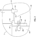
- Figure 2 illustrates an enlarged portion of turbine assembly 100 taken within area 2 of Figure 1 .
- inlet guide vanes 122 are coupled to an inner ring 124 that extends circumferentially about centerline axis 112.
- Inner ring 124 includes a plurality of circumferentially arranged segments 126 that each include a mounting flange 128 coupled to a wall 130 of casing 110 such that mounting flange 128 extends generally radially relative to centerline axis 112.
- Segments 126 also include a support flange 132 extending from mounting flange 128, and a lip 134 extending generally radially inward from support flange 132.
- each inlet guide vane 122 is seated in an opening 136 that extends through a support flange 132 of a respective segment 126. Accordingly, each segment 126 of inner ring 124 supports a plurality of inlet guide vanes 122 in the exemplary embodiment. In other embodiments, inner ring 124 may have any suitable cross-sectional shape, any suitable quantity of segments 126, and/or any suitable quantity of inlet guide vanes 122 per segment 126.
- each segment 126 is coupled to casing wall 130 via at least one fastener 138 that extends through mounting flange 128 and is installed in wall 130.
- segments 126 are individually detachable from casing 110 (and from each other) to facilitate removing inlet guide vanes 122 when servicing inlet guide vanes 122 and/or compressor 102, for example.
- the exemplary fasteners 138 are removable from casing wall 130 via a pulling action, and are likewise insertable into casing wall 130 via a pushing action.
- fasteners 138 may include dowel pins. In other embodiments, fasteners 138 may be of any suitable type that is insertable and/or removable in the manner described herein.
- each fastener 138 has a body (e.g., a dowel pin 140) that defines a threaded bore 142 therein, and a head (e.g., a shoulder head screw 144) selectively coupled within bore 142.
- a support flange 132 and a lip 134 of a respective segment 126 extend partly around fastener 138, segment 126 defines an interior space 146 that somewhat confines fastener 138 in a manner that makes fastener 138 difficult to access. It may, therefore, be difficult to align and operate some tools such as wrenches, for example, within interior space 146 to manually remove a fastener 138 from casing 110 using, for example, a jacking nut assembly.
- Figures 3 is a perspective view of an exemplary tool 200 that may be used to remove fasteners 138 from casing 110.
- Figures 4 and 5 are perspective and schematic cross-sectional views, respectively, of tool 200 during the removal of a fastener 138 from casing 110.
- Tool 200 includes a body 202, a puller 204 slidably coupled to body 202.
- tool 200 further comprises a shield 206 (e.g., a finger guard) coupled to body 202 such that shield 206 at least partially surrounds puller 204.
- a shield 206 e.g., a finger guard
- Puller 204 includes a plate 210 and an arm 212 extending from plate 210. Puller 204 further comprises a pair of plunger assemblies 214 extending from plate 210 on opposing sides of arm 212. As such, each plunger assembly 214 is oriented substantially parallel to arm 212. Arm 212 has a proximal end 216 that is formed integrally with plate 210, and a distal end 218 that defines an open-ended slot 220 that is sized to receive and engage shoulder head screw 144 when shoulder head screw 144 is coupled to dowel pin 140.
- Each plunger assembly 214 includes a piston 222, a plate screw 224, and a stop screw 226.
- Piston 222 has a proximal end 228 that defines a threaded bore 230, and a distal end 232 that defines a threaded bore 234.
- Each plate screw 224 is coupled within a threaded bore 230 of a respective piston 222 to secure the respective piston 222 to plate 210.
- each stop screw 226 is coupled within a threaded bore 234 of a respective piston 222.
- each stop screw 226 includes a plurality of peripherally spaced-apart notches 236 that facilitate fluid flow across stop screw 226 as described in more detail below.
- each plunger assembly 214 may have any suitable configuration that facilitates enabling puller 204 to function as described herein.
- each plunger assembly 214 may be a single-piece, integrally-molded structure, rather than having separate piston 222 and screws 224 and 226 as described above.
- body 202 is generally U-shaped and has a first leg member 240, a second leg member 242, and a bridge member 244 extending between first leg member 240 and second leg member 242 such that a passage 246 is defined between first leg member 240 and second leg member 242.
- Body 202 includes a contact face 248, a puller face 250 opposite contact face 248, and a side surface 252 extending from contact face 248 to puller face 250.
- a cylinder 254 and an adjacent sleeve 256 extend into each leg member 240 and 242 from puller face 250 in a substantially parallel orientation relative to passage 246.
- a hose socket 258 defined in side surface 252 is in flow communication with cylinders 254 via a suitable network of internal fluid conduits 260 within body 202.
- body 202 also includes a pair of bushings 262 that are each fitted (e.g., threaded) into a counterbore 264 defined about a respective one of cylinders 254.
- a seal 266 e.g., an O-ring or other suitable hydraulic seal is positioned at the interface of each bushing 262 and its associated leg member 240 or 242.
- Body 202 may have any suitable shape (e.g., body 202 may not be generally U-shaped), body 202 may have any suitable quantity of cylinders 254 (e.g., body 202 may have only one cylinder 254), and/or body 202 may have any suitable quantity of sleeves 256 (e.g., body 202 may not have any sleeves 256).
- puller 204 may have any suitable quantity of plunger assemblies 214 (e.g., puller 204 may have only one plunger assembly 214 if, for example, body 202 has only one cylinder 254).
- puller 204 is coupled to body 202 such that arm 212 extends into passage 246 between leg members 240 and 242, with each piston 222 extending through a respective bushing 262 and into a respective cylinder 254.
- each corresponding stop screw 226 slides in a tight tolerance within an internal surface 268 of its respective cylinder 254, with a seal 269 (e.g., an O-ring or other suitable hydraulic seal) positioned at the interface of each piston 222 and its associated bushing 262.
- each bushing 262 may be split into segments to facilitate coupling seal 269 to bushing 262 (e.g., by inserting seal 269 between split segments of bushing 262).
- puller 204 is also coupled to body 202 via a pair of return springs 270 that each extend from plate 210 into a respective sleeve 256.
- Return springs 270 bias plate 210 towards puller face 250 of body 202 in a biasing direction 280 such that plate 210 is seated against face 250.
- tool 200 With plate 210 seated against face 250 (as shown in Figure 3 ), tool 200 is said to be in its inactivated (or resting) state such that distal end 218 (i.e., slot 220) is substantially aligned with contact face 248 of body 202.
- each return spring 270 is coupled to body 202 and plate 210 via a hook 282 and stake 284 engagement, return springs 270 may be coupled to body 202 and plate 210 in any suitable manner in other embodiments.
- tool 200 is initially inserted into interior space 146. More specifically, initially tool 200 is in its inactivated state (as shown in Figure 3 ), such that contact face 248 slides towards support flange 132 along mounting flange 128 until slot 220 slidably engages shoulder head screw 144. After shoulder head screw 144 has been seated in slot 220, in the exemplary embodiment, a hydraulic or pneumatic pump (not shown) coupled to socket 258 is actuated to deliver a suitable working fluid (e.g., oil) through the network of internal conduits 260 and into cylinders 254.
- a suitable working fluid e.g., oil
- the working fluid fills (or pressurizes) cylinders 254 to displace pistons 222 (and, therefore, plate 210 and arm 212) of puller 204 away from puller face 250 of body 202 in a pulling direction 286 that is opposite biasing direction 280.
- the fastener 138 engaged by arm 212 is pulled from wall 130 of casing 110, in which position tool 200 is said to be in its activated state (as shown in Figures 4 and 5 ).
- shield 206 facilitates preventing the operator's fingers from being placed on puller face 250 or plate 210, and preventing the operator's fingers from being caught between plate 210 and body 202, and/or between plate 210 and nearby structure(s) (e.g., lip 134 of inner ring 124), when cylinders 254 are pressurized and depressurized.
- puller plate 210 may also include a slot (not shown) for engaging a shoulder head screw 144 such that tool 200 may be inserted into interior space 146 to engage and re-install an already-pulled fastener 138 via plate 210.
- puller plate 210 may be capable of engaging and pushing (or re-inserting) an already-pulled fastener 138 back into wall 130 of casing 110 upon pressurization of cylinders 254.
- tool 200 may be useful for both pulling installed fasteners 138, and for installing pulled fasteners 138, in some embodiments.
- tool 200 is sized for handheld operation (i.e., tool 200 can be coupled to, and decoupled from, an associated fastener 138 in an elevated position using only one hand).
- tool 200 is sized for handheld operation in the sense that tool 200 can be activated (either by the operator that is holding tool 200 or by another operator) while tool 200 is being held in the elevated position using only one hand.
- tool 200 may be sized such that, in its activated state, tool 200 has a height 288 of about two inches (as measured, for example, from body contact face 248 to an outer face 292 of plate 210), and a length 290 of about four inches (as measured, for example, from a first extent 294 of side surface 252 to a second extent 296 of side surface 252).
- tool 200 is sized for easier handling when removing fasteners from elevated locations, and is sized to fit within smaller spaces (e.g., interior space 146) for pulling harder-to-reach fasteners (e.g., fasteners 138).
- tool 200 may not be sized for handheld operation as set forth above (i.e., some embodiments of tool 200 may be sized such that tool 200 cannot be coupled to, and decoupled from, an associated fastener 138 in an elevated position using only one hand).
- the pump connected to tool 200 may be a hand-actuated pump, not an electrically actuated pump, to facilitate enabling more precise control over the amount of working fluid supplied to cylinders 254, thereby inhibiting the over-pressurization of cylinders 254.
- tool 200 may be operable only with a pump having a pressure rating of less than about seven hundred bars.
- the operator holding tool 200 may actuate the associated pump, or another operator may actuate the associated pump.
- one operator may repeatedly insert tool 200 into, and remove tool 200 from, interior space 146 for pulling one fastener 138 after the next, while another operator selectively hand-actuates the associated pump, thereby facilitating a more rapid process by which fasteners 138 are pulled from wall 130 of casing 110 about inner ring 124 in a shorter period of time.
- the pump may be any suitable pump, including an electrically actuated pump.
- other embodiments of tool 200 may utilize a suitable arrangement of gears/levers that facilitates displacing puller 204 relative to body 202 when removing and/or inserting fasteners 138.
- the methods and systems described herein facilitate the removal of fasteners in a less laborious and less time-consuming manner.
- the methods and systems also facilitate removing fasteners that are accessible only in smaller openings that are more difficult to reach.
- the methods and systems facilitate minimizing the amount of time needed to pull dowel pins that retain inlet guide vanes in a turbine assembly.
- the methods and systems facilitate reducing the amount of time needed to conduct an inspection, or to perform routine service, on the compressor of a turbine assembly.
- the methods and systems thereby facilitate reducing the amount of time that a turbine assembly is offline during inspection and/or servicing, which in turn facilitates reducing the overall cost associated with inspecting and/or servicing the turbine assembly.
Landscapes
- Engineering & Computer Science (AREA)
- Mechanical Engineering (AREA)
- Structures Of Non-Positive Displacement Pumps (AREA)
- Hand Tools For Fitting Together And Separating, Or Other Hand Tools (AREA)
- Turbine Rotor Nozzle Sealing (AREA)
Claims (9)
- Outil (200) pour retirer une fixation (138) d'un carter (110) d'un ensemble turbine (100) comprenant :un corps (202) comprenant un cylindre (254), une face de contact (248), une face d'extraction (250) opposée à la face de contact et une surface latérale (252) s'étendant de la face de contact à la face d'extraction,un extracteur (204) couplé audit corps faisant face à la face d'extraction, ledit extracteur comprend :une plaque (210),un bras (212) pour mettre en prise une fixation installée (138) ayant une extrémité proximale (216) qui est formée d'un seul tenant avec la plaque (210), et une extrémité distale (218) définissant une fente à extrémité ouverte (220) pour mettre en prise de manière coulissante la fixation (138) ;dans lequel l'extracteur est couplé au corps (202) par l'intermédiaire d'une paire de ressorts de rappel (270) qui sollicitent la plaque (210) dans une direction de sollicitation (280) vers le corps de telle sorte que l'extrémité distale (218) du bras (212) soit sensiblement alignée sur la face de contact (248) du corps (202) dans un état inactivé de l'outil (200),dans lequel l'extracteur comprend en outre un piston (222) inséré dans ledit cylindre (254) de telle sorte que ledit piston soit déplacé à l'intérieur dudit cylindre pour déplacer ladite plaque (210) et ledit bras (212) par rapport audit corps dans une direction opposée à la direction de sollicitation (280) lorsque ledit cylindre est sous pression, pour provoquer le retrait de la fixation (138).
- Outil de retrait de fixation selon la revendication 1, dans lequel ledit corps comprend une paire de cylindres, ledit extracteur comprend une paire de pistons insérés chacun dans un cylindre respectif desdits cylindres.
- Outil de retrait de fixation selon la revendication 1, comprenant en outre un ressort de rappel (270) sollicitant ledit extracteur (204) vers ledit corps (202).
- Outil de retrait de fixation selon la revendication 3, dans lequel ledit corps (202) comprend un manchon (256), ledit ressort de rappel (270) étant inséré dans ledit manchon dudit corps.
- Outil de retrait de fixation selon la revendication 1, dans lequel ledit corps est généralement en forme de U et comprend un premier élément de jambe (240), un second élément de jambe (242), et un élément de pont (244) couplant ledit premier élément de jambe audit second élément de jambe de telle sorte qu'un passage (246) soit défini entre lesdits premier et second éléments de jambe.
- Outil de retrait de fixation selon la revendication 1, comprenant en outre un écran (206) couplé audit corps (202) et entourant au moins partiellement ledit extracteur (204).
- Outil de retrait de fixation selon la revendication 1, ledit outil étant dimensionné pour un actionnement à la main.
- Procédé de retrait d'une fixation (138) d'un carter (110) d'un ensemble turbine (100), ledit procédé comprenant :le couplage d'un outil (200) à la fixation (138) dans lequel l'outil inclut un extracteur (204) ayant un bras (212) qui met en prise la fixation ; etla mise sous pression d'un cylindre (254) dans un corps (202) de l'outil de telle sorte qu'un piston (222) de l'extracteur (204) est déplacé à l'intérieur du cylindre pour retirer la fixation par l'intermédiaire du bras (212) de l'extracteur,caractérisé en ce que ledit procédé comprend en outre :
avant le couplage, l'insertion de l'outil (200) dans un espace intérieur (146) d'une bague interne (124) du carter (110) qui supporte une pluralité de palettes de guidage d'entrée (122) de l'ensemble turbine (100) et le coulissement de l'outil inséré le long d'une bride (128) de la bague interne (124) pour mettre en prise au moins l'une d'une vis à épaulement (144) et d'une goupille de positionnement (140) de la fixation (138) avec le bras (212). - Procédé selon la revendication 8, comprenant en outre la mise sous pression du cylindre (254) à l'aide d'une pompe à actionnement manuel.
Applications Claiming Priority (2)
| Application Number | Priority Date | Filing Date | Title |
|---|---|---|---|
| PL415762A PL415762A1 (pl) | 2016-01-11 | 2016-01-11 | Sposób i narzędzie do usuwania elementu mocującego |
| PCT/US2017/012263 WO2017123446A1 (fr) | 2016-01-11 | 2017-01-05 | Outil et procédés d'enlèvement de dispositif de fixation |
Publications (2)
| Publication Number | Publication Date |
|---|---|
| EP3402630A1 EP3402630A1 (fr) | 2018-11-21 |
| EP3402630B1 true EP3402630B1 (fr) | 2022-06-22 |
Family
ID=57882160
Family Applications (1)
| Application Number | Title | Priority Date | Filing Date |
|---|---|---|---|
| EP17701373.7A Active EP3402630B1 (fr) | 2016-01-11 | 2017-01-05 | Outil et procédés d'enlèvement de dispositif de fixation |
Country Status (4)
| Country | Link |
|---|---|
| US (1) | US11123848B2 (fr) |
| EP (1) | EP3402630B1 (fr) |
| PL (1) | PL415762A1 (fr) |
| WO (1) | WO2017123446A1 (fr) |
Cited By (1)
| Publication number | Priority date | Publication date | Assignee | Title |
|---|---|---|---|---|
| EP4606992A1 (fr) * | 2024-02-20 | 2025-08-27 | General Electric Technology GmbH | Kit de retrait de broche de segment d'aube directrice d'entrée |
Families Citing this family (6)
| Publication number | Priority date | Publication date | Assignee | Title |
|---|---|---|---|---|
| CN109926976B (zh) * | 2019-04-28 | 2020-10-13 | 安徽巨一科技股份有限公司 | 一种兼容压装和拉除的机身结构 |
| ES3013310T3 (en) * | 2019-09-23 | 2025-04-11 | Cqms Pty Ltd | A device for removing a wear member |
| US11578616B2 (en) * | 2021-02-05 | 2023-02-14 | Pratt & Whitney Canada Corp. | Gas turbine engine assembly and method of disassembling same |
| US12409518B2 (en) | 2022-04-26 | 2025-09-09 | United States Of America As Represented By The Secretary Of The Air Force | Fastener removal tool |
| CN116464523B (zh) * | 2023-05-25 | 2025-09-09 | 华能(上海)电力检修有限责任公司 | 一种筒式高压缸定位结构 |
| US12356530B1 (en) * | 2024-06-04 | 2025-07-08 | General Electric Company | Method of removing an insert from a substrate |
Citations (1)
| Publication number | Priority date | Publication date | Assignee | Title |
|---|---|---|---|---|
| US20120279065A1 (en) * | 2011-05-06 | 2012-11-08 | Clipper Windpower, Inc. | Method of extracting barrel nuts |
Family Cites Families (35)
| Publication number | Priority date | Publication date | Assignee | Title |
|---|---|---|---|---|
| US2735649A (en) * | 1956-02-21 | swallert | ||
| US2133697A (en) * | 1937-01-28 | 1938-10-18 | Hansen Birkelund | Valve lifter or valve puller |
| US2507003A (en) * | 1948-11-22 | 1950-05-09 | Hein Werner Corp | Yoke and drawbar element for hydraulic sleeve-pulling devices |
| US2874933A (en) * | 1955-03-16 | 1959-02-24 | Cleveland Rock Drill Division | Power actuated pin puller |
| US2883741A (en) * | 1957-03-27 | 1959-04-28 | William M Yerkes | Diesel injection nozzle puller |
| FR1390415A (fr) * | 1964-01-16 | 1965-02-26 | Commissariat Energie Atomique | Appareil d'extraction de bagues |
| US4078766A (en) * | 1977-04-11 | 1978-03-14 | Saurwein Albert C | Powered nail extractor |
| DE3142689A1 (de) * | 1981-10-28 | 1983-05-11 | Kurt 8416 Hemau Unger | Tuerbolzenabziehvorrichtung |
| US4429857A (en) * | 1983-01-26 | 1984-02-07 | Ferguson W Gardner | Apparatus for integrally removing a track plate and spikes |
| US4542570A (en) * | 1983-09-13 | 1985-09-24 | Vernon Prince | Portable fan blade and sheave removing device |
| GB8629448D0 (en) | 1986-12-09 | 1987-01-21 | Spooner R P | Extractor |
| DE3730214A1 (de) * | 1987-09-09 | 1989-03-30 | Horst Klann | Hydraulische ziehvorrichtung |
| US4903392A (en) * | 1988-06-22 | 1990-02-27 | Westinghouse Electric Corp. | Method for removing a metallic plug from a tube by simultaneously heating and stretching the plug |
| US4995158A (en) * | 1989-02-08 | 1991-02-26 | Westinghouse Electric Corp. | Apparatus for servicing a jet pump hold down beam in a nuclear reactor |
| CA2029335A1 (fr) * | 1990-11-05 | 1992-05-06 | David W. Reesor | Extracteur permettant de retirer la clavette de l'appareil de traction d'un attelage de wagons |
| DE4204657C1 (fr) * | 1992-02-15 | 1993-08-05 | Abb Reaktor Gmbh, 6800 Mannheim, De | |
| US5701649A (en) * | 1996-04-16 | 1997-12-30 | Hydra-Tech International Corporation | Coupled draft key puller |
| US6113073A (en) * | 1999-06-22 | 2000-09-05 | Framatome Connectors Usa, Inc. | Hydraulic spike puller with frictionally delayed moving jaws and blocking jaw front shape |
| GB9917790D0 (en) * | 1999-07-30 | 1999-09-29 | British Aerospace | Extractor device |
| US6526641B1 (en) * | 1999-11-01 | 2003-03-04 | Keystone Engineering & Manufacturing Company | Device for separating cutting bits from holders |
| US6978527B2 (en) * | 2002-12-13 | 2005-12-27 | General Electric Company | Fuel injector removal tool |
| US6910252B2 (en) * | 2003-03-27 | 2005-06-28 | The Boeing Company | Apparatus for removing a fastener from a workpiece |
| EP1977861A1 (fr) * | 2007-04-05 | 2008-10-08 | Siemens Aktiengesellschaft | Tire goupille en plusieurs parties destiné à l'extraction d'une goupille ou d'un boulon d'un orifice d'un composant |
| US7658368B2 (en) * | 2007-09-21 | 2010-02-09 | Laun Craig M | Nail extractor |
| US8146221B2 (en) * | 2008-10-22 | 2012-04-03 | Jung-Liang Hung | Hydraulic tool |
| CA2652068C (fr) * | 2009-01-30 | 2011-07-05 | Brian Tucken | Appareil de poussee-tirage et structure de support pour foreuse sous pression ou appareillage semblable sur un plancher de forage |
| CN101698277A (zh) * | 2009-08-28 | 2010-04-28 | 枣庄矿业集团付村煤业有限公司 | 液压退销器 |
| CN101927429B (zh) * | 2010-08-28 | 2012-05-09 | 淄博矿业集团有限责任公司 | 双缸液压拔销器 |
| US8910357B2 (en) * | 2011-05-26 | 2014-12-16 | General Electric Company | Tool for removing pins from a gas turbine casing |
| CN103769843A (zh) * | 2012-10-23 | 2014-05-07 | 湖北兴发化工集团股份有限公司 | 可调锥形销液压拉拔器 |
| CN104175278A (zh) * | 2013-05-24 | 2014-12-03 | 富泰华工业(深圳)有限公司 | 拔销器 |
| CN104440026B (zh) * | 2013-09-13 | 2016-11-23 | 南京泉峰汽车精密技术有限公司 | 动力拔销器 |
| US9381602B2 (en) * | 2014-05-14 | 2016-07-05 | General Electric Company | Turbomachine bucket displacement apparatus and method of use |
| US9737981B2 (en) * | 2014-07-25 | 2017-08-22 | Pro Tools, Llc | Universal joint dismantling tool |
| EP3156179B1 (fr) * | 2015-10-12 | 2018-12-26 | Wallmek i Kungälv AB | Cylindre hydraulique à action unique |
-
2016
- 2016-01-11 PL PL415762A patent/PL415762A1/pl unknown
-
2017
- 2017-01-05 WO PCT/US2017/012263 patent/WO2017123446A1/fr not_active Ceased
- 2017-01-05 US US16/067,704 patent/US11123848B2/en active Active
- 2017-01-05 EP EP17701373.7A patent/EP3402630B1/fr active Active
Patent Citations (1)
| Publication number | Priority date | Publication date | Assignee | Title |
|---|---|---|---|---|
| US20120279065A1 (en) * | 2011-05-06 | 2012-11-08 | Clipper Windpower, Inc. | Method of extracting barrel nuts |
Cited By (1)
| Publication number | Priority date | Publication date | Assignee | Title |
|---|---|---|---|---|
| EP4606992A1 (fr) * | 2024-02-20 | 2025-08-27 | General Electric Technology GmbH | Kit de retrait de broche de segment d'aube directrice d'entrée |
Also Published As
| Publication number | Publication date |
|---|---|
| WO2017123446A1 (fr) | 2017-07-20 |
| EP3402630A1 (fr) | 2018-11-21 |
| PL415762A1 (pl) | 2017-07-17 |
| US20190001472A1 (en) | 2019-01-03 |
| US11123848B2 (en) | 2021-09-21 |
Similar Documents
| Publication | Publication Date | Title |
|---|---|---|
| EP3402630B1 (fr) | Outil et procédés d'enlèvement de dispositif de fixation | |
| US8782865B2 (en) | Combustor liner and flow sleeve tool | |
| US8713776B2 (en) | System and tool for installing combustion liners | |
| US8910357B2 (en) | Tool for removing pins from a gas turbine casing | |
| EP3225779B1 (fr) | Outil d'extraction | |
| US8757962B2 (en) | System and method for adjusting a shroud block in a casing | |
| EP3330040B1 (fr) | Outil pour chemise de chambre de combustion | |
| EP3498427B1 (fr) | Outil d'installation d'insert à verrouillage par clé | |
| US10821583B2 (en) | Spring loaded pilot punch assembly | |
| EP2743458B1 (fr) | Appareil et procédé pour l'assemblage et le démontage d'une pièce de transition de turbine | |
| US9713862B2 (en) | Turbomachine component displacement apparatus and method of use | |
| US9816398B2 (en) | Turbine shroud block removal apparatus | |
| EP2660523B1 (fr) | Système et procédé permettant d'assembler un couvercle d'extrémité d'une chambre de combustion | |
| US11022147B2 (en) | Inlet guide vane removal tools and methods | |
| EP3255345A1 (fr) | Outil d'installation et système d'assemblage d'un dispositif de combustion de turbine à gaz | |
| CN108361733B (zh) | 燃烧筒维护设备及方法 | |
| EP3601991B1 (fr) | Outil d'essai de frein moteur | |
| CN217292169U (zh) | 危急遮断器检修工具组 | |
| RU2383878C1 (ru) | Ниппель для клапана-отсекателя и способ установки клапана-отсекателя в ниппель | |
| US4818216A (en) | Method and apparatus for removing fuel gun from boiler | |
| GB2435443A (en) | Ejector seat runner tube removal apparatus |
Legal Events
| Date | Code | Title | Description |
|---|---|---|---|
| STAA | Information on the status of an ep patent application or granted ep patent |
Free format text: STATUS: UNKNOWN |
|
| STAA | Information on the status of an ep patent application or granted ep patent |
Free format text: STATUS: THE INTERNATIONAL PUBLICATION HAS BEEN MADE |
|
| PUAI | Public reference made under article 153(3) epc to a published international application that has entered the european phase |
Free format text: ORIGINAL CODE: 0009012 |
|
| STAA | Information on the status of an ep patent application or granted ep patent |
Free format text: STATUS: REQUEST FOR EXAMINATION WAS MADE |
|
| 17P | Request for examination filed |
Effective date: 20180813 |
|
| AK | Designated contracting states |
Kind code of ref document: A1 Designated state(s): AL AT BE BG CH CY CZ DE DK EE ES FI FR GB GR HR HU IE IS IT LI LT LU LV MC MK MT NL NO PL PT RO RS SE SI SK SM TR |
|
| AX | Request for extension of the european patent |
Extension state: BA ME |
|
| DAV | Request for validation of the european patent (deleted) | ||
| DAX | Request for extension of the european patent (deleted) | ||
| STAA | Information on the status of an ep patent application or granted ep patent |
Free format text: STATUS: EXAMINATION IS IN PROGRESS |
|
| 17Q | First examination report despatched |
Effective date: 20190709 |
|
| GRAP | Despatch of communication of intention to grant a patent |
Free format text: ORIGINAL CODE: EPIDOSNIGR1 |
|
| STAA | Information on the status of an ep patent application or granted ep patent |
Free format text: STATUS: GRANT OF PATENT IS INTENDED |
|
| INTG | Intention to grant announced |
Effective date: 20220126 |
|
| GRAS | Grant fee paid |
Free format text: ORIGINAL CODE: EPIDOSNIGR3 |
|
| GRAA | (expected) grant |
Free format text: ORIGINAL CODE: 0009210 |
|
| STAA | Information on the status of an ep patent application or granted ep patent |
Free format text: STATUS: THE PATENT HAS BEEN GRANTED |
|
| AK | Designated contracting states |
Kind code of ref document: B1 Designated state(s): AL AT BE BG CH CY CZ DE DK EE ES FI FR GB GR HR HU IE IS IT LI LT LU LV MC MK MT NL NO PL PT RO RS SE SI SK SM TR |
|
| REG | Reference to a national code |
Ref country code: GB Ref legal event code: FG4D |
|
| REG | Reference to a national code |
Ref country code: CH Ref legal event code: EP |
|
| REG | Reference to a national code |
Ref country code: DE Ref legal event code: R096 Ref document number: 602017058722 Country of ref document: DE |
|
| REG | Reference to a national code |
Ref country code: AT Ref legal event code: REF Ref document number: 1499469 Country of ref document: AT Kind code of ref document: T Effective date: 20220715 |
|
| REG | Reference to a national code |
Ref country code: IE Ref legal event code: FG4D |
|
| REG | Reference to a national code |
Ref country code: LT Ref legal event code: MG9D |
|
| REG | Reference to a national code |
Ref country code: NL Ref legal event code: MP Effective date: 20220622 |
|
| PG25 | Lapsed in a contracting state [announced via postgrant information from national office to epo] |
Ref country code: SE Free format text: LAPSE BECAUSE OF FAILURE TO SUBMIT A TRANSLATION OF THE DESCRIPTION OR TO PAY THE FEE WITHIN THE PRESCRIBED TIME-LIMIT Effective date: 20220622 Ref country code: NO Free format text: LAPSE BECAUSE OF FAILURE TO SUBMIT A TRANSLATION OF THE DESCRIPTION OR TO PAY THE FEE WITHIN THE PRESCRIBED TIME-LIMIT Effective date: 20220922 Ref country code: LT Free format text: LAPSE BECAUSE OF FAILURE TO SUBMIT A TRANSLATION OF THE DESCRIPTION OR TO PAY THE FEE WITHIN THE PRESCRIBED TIME-LIMIT Effective date: 20220622 Ref country code: HR Free format text: LAPSE BECAUSE OF FAILURE TO SUBMIT A TRANSLATION OF THE DESCRIPTION OR TO PAY THE FEE WITHIN THE PRESCRIBED TIME-LIMIT Effective date: 20220622 Ref country code: GR Free format text: LAPSE BECAUSE OF FAILURE TO SUBMIT A TRANSLATION OF THE DESCRIPTION OR TO PAY THE FEE WITHIN THE PRESCRIBED TIME-LIMIT Effective date: 20220923 Ref country code: FI Free format text: LAPSE BECAUSE OF FAILURE TO SUBMIT A TRANSLATION OF THE DESCRIPTION OR TO PAY THE FEE WITHIN THE PRESCRIBED TIME-LIMIT Effective date: 20220622 Ref country code: BG Free format text: LAPSE BECAUSE OF FAILURE TO SUBMIT A TRANSLATION OF THE DESCRIPTION OR TO PAY THE FEE WITHIN THE PRESCRIBED TIME-LIMIT Effective date: 20220922 |
|
| REG | Reference to a national code |
Ref country code: AT Ref legal event code: MK05 Ref document number: 1499469 Country of ref document: AT Kind code of ref document: T Effective date: 20220622 |
|
| PG25 | Lapsed in a contracting state [announced via postgrant information from national office to epo] |
Ref country code: RS Free format text: LAPSE BECAUSE OF FAILURE TO SUBMIT A TRANSLATION OF THE DESCRIPTION OR TO PAY THE FEE WITHIN THE PRESCRIBED TIME-LIMIT Effective date: 20220622 Ref country code: LV Free format text: LAPSE BECAUSE OF FAILURE TO SUBMIT A TRANSLATION OF THE DESCRIPTION OR TO PAY THE FEE WITHIN THE PRESCRIBED TIME-LIMIT Effective date: 20220622 |
|
| PG25 | Lapsed in a contracting state [announced via postgrant information from national office to epo] |
Ref country code: NL Free format text: LAPSE BECAUSE OF FAILURE TO SUBMIT A TRANSLATION OF THE DESCRIPTION OR TO PAY THE FEE WITHIN THE PRESCRIBED TIME-LIMIT Effective date: 20220622 |
|
| PG25 | Lapsed in a contracting state [announced via postgrant information from national office to epo] |
Ref country code: SM Free format text: LAPSE BECAUSE OF FAILURE TO SUBMIT A TRANSLATION OF THE DESCRIPTION OR TO PAY THE FEE WITHIN THE PRESCRIBED TIME-LIMIT Effective date: 20220622 Ref country code: SK Free format text: LAPSE BECAUSE OF FAILURE TO SUBMIT A TRANSLATION OF THE DESCRIPTION OR TO PAY THE FEE WITHIN THE PRESCRIBED TIME-LIMIT Effective date: 20220622 Ref country code: RO Free format text: LAPSE BECAUSE OF FAILURE TO SUBMIT A TRANSLATION OF THE DESCRIPTION OR TO PAY THE FEE WITHIN THE PRESCRIBED TIME-LIMIT Effective date: 20220622 Ref country code: PT Free format text: LAPSE BECAUSE OF FAILURE TO SUBMIT A TRANSLATION OF THE DESCRIPTION OR TO PAY THE FEE WITHIN THE PRESCRIBED TIME-LIMIT Effective date: 20221024 Ref country code: ES Free format text: LAPSE BECAUSE OF FAILURE TO SUBMIT A TRANSLATION OF THE DESCRIPTION OR TO PAY THE FEE WITHIN THE PRESCRIBED TIME-LIMIT Effective date: 20220622 Ref country code: EE Free format text: LAPSE BECAUSE OF FAILURE TO SUBMIT A TRANSLATION OF THE DESCRIPTION OR TO PAY THE FEE WITHIN THE PRESCRIBED TIME-LIMIT Effective date: 20220622 Ref country code: CZ Free format text: LAPSE BECAUSE OF FAILURE TO SUBMIT A TRANSLATION OF THE DESCRIPTION OR TO PAY THE FEE WITHIN THE PRESCRIBED TIME-LIMIT Effective date: 20220622 Ref country code: AT Free format text: LAPSE BECAUSE OF FAILURE TO SUBMIT A TRANSLATION OF THE DESCRIPTION OR TO PAY THE FEE WITHIN THE PRESCRIBED TIME-LIMIT Effective date: 20220622 |
|
| PG25 | Lapsed in a contracting state [announced via postgrant information from national office to epo] |
Ref country code: PL Free format text: LAPSE BECAUSE OF FAILURE TO SUBMIT A TRANSLATION OF THE DESCRIPTION OR TO PAY THE FEE WITHIN THE PRESCRIBED TIME-LIMIT Effective date: 20220622 Ref country code: IS Free format text: LAPSE BECAUSE OF FAILURE TO SUBMIT A TRANSLATION OF THE DESCRIPTION OR TO PAY THE FEE WITHIN THE PRESCRIBED TIME-LIMIT Effective date: 20221022 |
|
| REG | Reference to a national code |
Ref country code: DE Ref legal event code: R097 Ref document number: 602017058722 Country of ref document: DE |
|
| PG25 | Lapsed in a contracting state [announced via postgrant information from national office to epo] |
Ref country code: AL Free format text: LAPSE BECAUSE OF FAILURE TO SUBMIT A TRANSLATION OF THE DESCRIPTION OR TO PAY THE FEE WITHIN THE PRESCRIBED TIME-LIMIT Effective date: 20220622 |
|
| PG25 | Lapsed in a contracting state [announced via postgrant information from national office to epo] |
Ref country code: DK Free format text: LAPSE BECAUSE OF FAILURE TO SUBMIT A TRANSLATION OF THE DESCRIPTION OR TO PAY THE FEE WITHIN THE PRESCRIBED TIME-LIMIT Effective date: 20220622 |
|
| PLBE | No opposition filed within time limit |
Free format text: ORIGINAL CODE: 0009261 |
|
| STAA | Information on the status of an ep patent application or granted ep patent |
Free format text: STATUS: NO OPPOSITION FILED WITHIN TIME LIMIT |
|
| 26N | No opposition filed |
Effective date: 20230323 |
|
| PG25 | Lapsed in a contracting state [announced via postgrant information from national office to epo] |
Ref country code: SI Free format text: LAPSE BECAUSE OF FAILURE TO SUBMIT A TRANSLATION OF THE DESCRIPTION OR TO PAY THE FEE WITHIN THE PRESCRIBED TIME-LIMIT Effective date: 20220622 |
|
| REG | Reference to a national code |
Ref country code: CH Ref legal event code: PL |
|
| PG25 | Lapsed in a contracting state [announced via postgrant information from national office to epo] |
Ref country code: LU Free format text: LAPSE BECAUSE OF NON-PAYMENT OF DUE FEES Effective date: 20230105 |
|
| REG | Reference to a national code |
Ref country code: BE Ref legal event code: MM Effective date: 20230131 |
|
| PG25 | Lapsed in a contracting state [announced via postgrant information from national office to epo] |
Ref country code: LI Free format text: LAPSE BECAUSE OF NON-PAYMENT OF DUE FEES Effective date: 20230131 Ref country code: CH Free format text: LAPSE BECAUSE OF NON-PAYMENT OF DUE FEES Effective date: 20230131 |
|
| REG | Reference to a national code |
Ref country code: DE Ref legal event code: R081 Ref document number: 602017058722 Country of ref document: DE Owner name: GENERAL ELECTRIC TECHNOLOGY GMBH, CH Free format text: FORMER OWNER: GENERAL ELECTRIC COMPANY, SCHENECTADY, NY, US |
|
| PG25 | Lapsed in a contracting state [announced via postgrant information from national office to epo] |
Ref country code: FR Free format text: LAPSE BECAUSE OF NON-PAYMENT OF DUE FEES Effective date: 20230131 Ref country code: BE Free format text: LAPSE BECAUSE OF NON-PAYMENT OF DUE FEES Effective date: 20230131 |
|
| PG25 | Lapsed in a contracting state [announced via postgrant information from national office to epo] |
Ref country code: IE Free format text: LAPSE BECAUSE OF NON-PAYMENT OF DUE FEES Effective date: 20230105 |
|
| REG | Reference to a national code |
Ref country code: GB Ref legal event code: 732E Free format text: REGISTERED BETWEEN 20240222 AND 20240228 |
|
| PG25 | Lapsed in a contracting state [announced via postgrant information from national office to epo] |
Ref country code: MC Free format text: LAPSE BECAUSE OF FAILURE TO SUBMIT A TRANSLATION OF THE DESCRIPTION OR TO PAY THE FEE WITHIN THE PRESCRIBED TIME-LIMIT Effective date: 20220622 |
|
| PG25 | Lapsed in a contracting state [announced via postgrant information from national office to epo] |
Ref country code: MC Free format text: LAPSE BECAUSE OF FAILURE TO SUBMIT A TRANSLATION OF THE DESCRIPTION OR TO PAY THE FEE WITHIN THE PRESCRIBED TIME-LIMIT Effective date: 20220622 |
|
| PG25 | Lapsed in a contracting state [announced via postgrant information from national office to epo] |
Ref country code: BG Free format text: LAPSE BECAUSE OF FAILURE TO SUBMIT A TRANSLATION OF THE DESCRIPTION OR TO PAY THE FEE WITHIN THE PRESCRIBED TIME-LIMIT Effective date: 20220622 |
|
| PG25 | Lapsed in a contracting state [announced via postgrant information from national office to epo] |
Ref country code: BG Free format text: LAPSE BECAUSE OF FAILURE TO SUBMIT A TRANSLATION OF THE DESCRIPTION OR TO PAY THE FEE WITHIN THE PRESCRIBED TIME-LIMIT Effective date: 20220622 |
|
| PG25 | Lapsed in a contracting state [announced via postgrant information from national office to epo] |
Ref country code: CY Free format text: LAPSE BECAUSE OF FAILURE TO SUBMIT A TRANSLATION OF THE DESCRIPTION OR TO PAY THE FEE WITHIN THE PRESCRIBED TIME-LIMIT; INVALID AB INITIO Effective date: 20170105 |
|
| PG25 | Lapsed in a contracting state [announced via postgrant information from national office to epo] |
Ref country code: HU Free format text: LAPSE BECAUSE OF FAILURE TO SUBMIT A TRANSLATION OF THE DESCRIPTION OR TO PAY THE FEE WITHIN THE PRESCRIBED TIME-LIMIT; INVALID AB INITIO Effective date: 20170105 |
|
| PG25 | Lapsed in a contracting state [announced via postgrant information from national office to epo] |
Ref country code: TR Free format text: LAPSE BECAUSE OF FAILURE TO SUBMIT A TRANSLATION OF THE DESCRIPTION OR TO PAY THE FEE WITHIN THE PRESCRIBED TIME-LIMIT Effective date: 20220622 |
|
| PGFP | Annual fee paid to national office [announced via postgrant information from national office to epo] |
Ref country code: GB Payment date: 20251217 Year of fee payment: 10 |
|
| PGFP | Annual fee paid to national office [announced via postgrant information from national office to epo] |
Ref country code: DE Payment date: 20251217 Year of fee payment: 10 |
|
| PGFP | Annual fee paid to national office [announced via postgrant information from national office to epo] |
Ref country code: IT Payment date: 20260107 Year of fee payment: 10 |