EP3402614B1 - Aluminium foil rolling process - Google Patents
Aluminium foil rolling process Download PDFInfo
- Publication number
- EP3402614B1 EP3402614B1 EP16829438.7A EP16829438A EP3402614B1 EP 3402614 B1 EP3402614 B1 EP 3402614B1 EP 16829438 A EP16829438 A EP 16829438A EP 3402614 B1 EP3402614 B1 EP 3402614B1
- Authority
- EP
- European Patent Office
- Prior art keywords
- foil
- aluminium foil
- coupled
- face
- aluminium
- Prior art date
- Legal status (The legal status is an assumption and is not a legal conclusion. Google has not performed a legal analysis and makes no representation as to the accuracy of the status listed.)
- Active
Links
Images

Classifications
-
- B—PERFORMING OPERATIONS; TRANSPORTING
- B21—MECHANICAL METAL-WORKING WITHOUT ESSENTIALLY REMOVING MATERIAL; PUNCHING METAL
- B21B—ROLLING OF METAL
- B21B1/00—Metal-rolling methods or mills for making semi-finished products of solid or profiled cross-section; Sequence of operations in milling trains; Layout of rolling-mill plant, e.g. grouping of stands; Succession of passes or of sectional pass alternations
- B21B1/38—Metal-rolling methods or mills for making semi-finished products of solid or profiled cross-section; Sequence of operations in milling trains; Layout of rolling-mill plant, e.g. grouping of stands; Succession of passes or of sectional pass alternations for rolling sheets of limited length, e.g. folded sheets, superimposed sheets, pack rolling
-
- B—PERFORMING OPERATIONS; TRANSPORTING
- B21—MECHANICAL METAL-WORKING WITHOUT ESSENTIALLY REMOVING MATERIAL; PUNCHING METAL
- B21B—ROLLING OF METAL
- B21B3/00—Rolling materials of special alloys so far as the composition of the alloy requires or permits special rolling methods or sequences ; Rolling of aluminium, copper, zinc or other non-ferrous metals
-
- B—PERFORMING OPERATIONS; TRANSPORTING
- B21—MECHANICAL METAL-WORKING WITHOUT ESSENTIALLY REMOVING MATERIAL; PUNCHING METAL
- B21B—ROLLING OF METAL
- B21B45/00—Devices for surface or other treatment of work, specially combined with or arranged in, or specially adapted for use in connection with, metal-rolling mills
- B21B45/02—Devices for surface or other treatment of work, specially combined with or arranged in, or specially adapted for use in connection with, metal-rolling mills for lubricating, cooling, or cleaning
- B21B45/0239—Lubricating
- B21B45/0245—Lubricating devices
- B21B45/0248—Lubricating devices using liquid lubricants, e.g. for sections, for tubes
- B21B45/0251—Lubricating devices using liquid lubricants, e.g. for sections, for tubes for strips, sheets, or plates
-
- B—PERFORMING OPERATIONS; TRANSPORTING
- B21—MECHANICAL METAL-WORKING WITHOUT ESSENTIALLY REMOVING MATERIAL; PUNCHING METAL
- B21B—ROLLING OF METAL
- B21B47/00—Auxiliary arrangements, devices or methods in connection with rolling of multi-layer sheets of metal
- B21B47/04—Auxiliary arrangements, devices or methods in connection with rolling of multi-layer sheets of metal for separating layers after rolling
-
- B—PERFORMING OPERATIONS; TRANSPORTING
- B23—MACHINE TOOLS; METAL-WORKING NOT OTHERWISE PROVIDED FOR
- B23P—METAL-WORKING NOT OTHERWISE PROVIDED FOR; COMBINED OPERATIONS; UNIVERSAL MACHINE TOOLS
- B23P25/00—Auxiliary treatment of workpieces, before or during machining operations, to facilitate the action of the tool or the attainment of a desired final condition of the work, e.g. relief of internal stress
-
- B—PERFORMING OPERATIONS; TRANSPORTING
- B21—MECHANICAL METAL-WORKING WITHOUT ESSENTIALLY REMOVING MATERIAL; PUNCHING METAL
- B21B—ROLLING OF METAL
- B21B1/00—Metal-rolling methods or mills for making semi-finished products of solid or profiled cross-section; Sequence of operations in milling trains; Layout of rolling-mill plant, e.g. grouping of stands; Succession of passes or of sectional pass alternations
- B21B1/38—Metal-rolling methods or mills for making semi-finished products of solid or profiled cross-section; Sequence of operations in milling trains; Layout of rolling-mill plant, e.g. grouping of stands; Succession of passes or of sectional pass alternations for rolling sheets of limited length, e.g. folded sheets, superimposed sheets, pack rolling
- B21B2001/383—Cladded or coated products
-
- B—PERFORMING OPERATIONS; TRANSPORTING
- B21—MECHANICAL METAL-WORKING WITHOUT ESSENTIALLY REMOVING MATERIAL; PUNCHING METAL
- B21B—ROLLING OF METAL
- B21B3/00—Rolling materials of special alloys so far as the composition of the alloy requires or permits special rolling methods or sequences ; Rolling of aluminium, copper, zinc or other non-ferrous metals
- B21B2003/001—Aluminium or its alloys
-
- B—PERFORMING OPERATIONS; TRANSPORTING
- B21—MECHANICAL METAL-WORKING WITHOUT ESSENTIALLY REMOVING MATERIAL; PUNCHING METAL
- B21B—ROLLING OF METAL
- B21B15/00—Arrangements for performing additional metal-working operations specially combined with or arranged in, or specially adapted for use in connection with, metal-rolling mills
- B21B2015/0057—Coiling the rolled product
-
- B—PERFORMING OPERATIONS; TRANSPORTING
- B21—MECHANICAL METAL-WORKING WITHOUT ESSENTIALLY REMOVING MATERIAL; PUNCHING METAL
- B21B—ROLLING OF METAL
- B21B15/00—Arrangements for performing additional metal-working operations specially combined with or arranged in, or specially adapted for use in connection with, metal-rolling mills
- B21B2015/0064—Uncoiling the rolled product
-
- B—PERFORMING OPERATIONS; TRANSPORTING
- B23—MACHINE TOOLS; METAL-WORKING NOT OTHERWISE PROVIDED FOR
- B23P—METAL-WORKING NOT OTHERWISE PROVIDED FOR; COMBINED OPERATIONS; UNIVERSAL MACHINE TOOLS
- B23P13/00—Making metal objects by operations essentially involving machining but not covered by a single other subclass
- B23P13/02—Making metal objects by operations essentially involving machining but not covered by a single other subclass in which only the machining operations are important
-
- B—PERFORMING OPERATIONS; TRANSPORTING
- B23—MACHINE TOOLS; METAL-WORKING NOT OTHERWISE PROVIDED FOR
- B23P—METAL-WORKING NOT OTHERWISE PROVIDED FOR; COMBINED OPERATIONS; UNIVERSAL MACHINE TOOLS
- B23P2700/00—Indexing scheme relating to the articles being treated, e.g. manufactured, repaired, assembled, connected or other operations covered in the subgroups
- B23P2700/12—Laminated parts
Definitions
- the present invention relates to a process for making aluminium foils with reduced thickness, for example but not exclusively, for use as flexible packaging, and in particular relates to an aluminium foil rolling process.
- aluminium foils of reduced thickness are usually employed.
- Aluminium foils of the aforementioned type widely but improperly known also as tin foil or silver paper, are in practice foils with thickness of the order of some thousandth of millimeter, obtained by rolling aluminium foils having larger thickness.
- the known art provided some processes wherein, after some steps of singly rolling in which each foil is rolled individually, a final doubly rolling step is provided wherein two coupled foils, i.e. overlapped one to another, are rolled together.
- the coupling of two aluminium foils can be carried out substantially concurrently with the rolling, thus in the same machine named rolling mill, or it can be carried out before the rolling in a different machine named doubling machine and arranged upstream of the rolling mill.
- DE 19927697 A1 shows an aluminium foil rolling process comprising the steps of: a) providing at least one first aluminium foil and one second aluminium foil each having a respective first face and a respective second face; b) lubricating at least one face between said first face and said second face of at least one aluminium foil between said first aluminium foil and said second aluminium foil, thereby obtaining at least one first lubricated face; c) coupling said first aluminium foil with said second aluminium foil, so that said at least one first lubricated face is a contact face between said first aluminium foil and said second aluminium foil, thereby obtaining a coupled foil having two outer faces; d) rolling said coupled foil with reduction of the thickness of said coupled foil; f) winding at least partially said coupled foil, obtaining an at least partially wound coupled foil comprising n turns; 1) separating said coupled foil with reduced thickness thereby obtaining
- the technical problem underlying the present invention has been to provide a process for making aluminium foils with reduced thickness having characteristics such as to overcome the drawbacks mentioned above with reference to the known art.
- an aluminium foils rolling process comprising the steps of:
- two aluminium foils overlapped one to another to form a coupled foil are doubly rolled several times, i.e. together, without the need of wholly separating the same between a doubly rolling step and a subsequent doubly rolling step to interpose some lubricant between them, rather the two aluminium foils remain mostly overlapped to form the coupled foil that is wound (rolled up) after a doubly rolling step and unwound (unrolled) before the subsequent doubly rolling step, or substantially concurrently therewith, upon lubricating before the afore said subsequent doubly laminating step of at least one its outer face and partially unwinding only one of the two aluminium foils, thus with separation of the coupled foil only limited to the outermost turn of the afore said n turns of the wound coupled foil.
- the afore said process comprises a step m), wherein the afore said end portion constituted by a respective portion of only one of the afore said first aluminium foil and the afore said second aluminium foil, obtained in the afore said step g), is removed from the coupled foil, preferably removed by cutting the same.
- the afore said step e) can precede the afore said step d) or be substantially concurrent therewith, as well as it can precede the afore said step f) or be substantially concurrent therewith.
- both the afore said outer faces of the afore said coupled foil are lubricated.
- two faces are lubricated, one face per each of the afore said first aluminium foil and second aluminium foil.
- the afore said process comprises at least one step n) of singly rolling, wherein at least one of the afore said first aluminium foil and the afore said second aluminium foil is individually rolled.
- the afore said process comprises a step o) of lubricating wherein at least one outer face of the coupled foil with reduced thickness obtained in the afore said step i) is at least partially lubricated, in particular if a further doubly rolling step is provided.
- the afore said process comprises further steps essentially similar to the afore said steps f), g), h) and i).
- the afore said process comprises a final step p) wherein the afore said first aluminium foil with a first reduced thickness and the afore said second aluminium foil with a second reduced thickness are singly wound in respective bobbins.
- the present process substantially comprises at least two doubly rolling steps, wherein a first aluminium foil denoted with 1, and a second aluminium foil denoted with 2, are coupled rolled, and wherein between the two steps of doubly rolling the first and second aluminium foils remain substantially overlapped one to another, as it will be better evident in the following.
- first aluminium foil 1 and the second aluminium foil 2 each having a respective first face 3, 4 and a respective second face 5, 6, where appropriate can be subjected to one or more singly rolling steps, wherein each aluminium foil is individually rolled in order to reduce the initial thickness thereof, such singly rolling steps not being depicted in figures.
- a lubricating step (step b) is provided, wherein at least one face of the first face and the second face of at least one aluminium foil between the first aluminium foil and the second aluminium foil is at least partially lubricated, for example by spraying lubricant, thereby obtaining a respective first lubricated face.
- the first face 3 of the first aluminium foil 1 is lubricated while the latter is unrolled from a respective first bobbin 7, while the second aluminium foil 2 is unrolled from a respective second bobbin 8.
- a coupling step of the first aluminium foil 1 with the second aluminium foil 2 is provided, also defined as doubling step (step c), wherein the first aluminium foil 1 is overlapped to the second aluminium foil 2 so that the first lubricated face, specifically the first face 3 of the first aluminium foil 1, is a contact face between the first aluminium foil 1 and the second aluminium foil 2.
- a coupled foil 9 is obtained and has two outer faces, that is subjected to a rolling step (step d) that causes a reduction of the thickness thereof, for example by a conventional rolling mill 10.
- the rolling step of the coupled foil 9 is also described as doubly rolling.
- the coupled foil 9 is lubricated on at least one of its two outer faces, for example by spraying other lubricant L.
- step e a lubricating step is provided, leading to obtain a coupled foil having at least one second lubricated face, in the examples of the figures denoted with 11 on the whole.
- the lubricating of an outer face of the coupled foil 9 occurs after the doubly rolling step, the possibility of lubricating an outer face of the coupled foil before the doubly rolling step not being however excluded.
- step f a winding step (step f) is provided, wherein the coupled foil having a second lubricated face 11 is rolled up, thereby obtaining a wound coupled foil comprising n turns, denoted with 12.
- Substantially the coupled foil having a second lubricated face 11 is wound n times to form a respective bobbin comprising the afore said n turns.
- a step of partially separating the wound coupled foil 12 (step g) is provided, wherein one of the first aluminium foil 1 and the second aluminium foil 2 is unrolled of one turn.
- the first aluminium foil 1 is unwound of one turn, therefore of one spiral, i.e. the outermost portion thereof in the afore said bobbin.
- a wound coupled foil is therefore obtained, on the whole denoted with 13, comprising an end portion 14 constituted by a respective portion of only one of the first aluminium foil and the second aluminium foil, in accordance with the examples of the figures such an end portion 14 being constituted by a respective portion of the first aluminium foil 1.
- the lubricant L initially arranged on an outer face of the coupled foil will be interposed between the first and second aluminium foils, the position of the two aluminium foils being reversed in the wound coupled foil 13 after the unwinding of one turn, which is limited to only one of the aluminium foils.
- the wound coupled foil 13 is thus unwound, i.e. unrolled, to be doubly rolled.
- a step of unwinding the wound coupled foil 13 (step h), wherein the afore said second lubricated face is a contact face between the first aluminium foil 1 and the second aluminium foil 2, and a doubly rolling step (second doubly rolling or step i) of the same coupled foil, wherein the second lubricated face is a contact face between the first aluminium foil 1 and the second aluminium foil 2, are therefore provided, thereby obtaining a coupled foil with reduced thickness, denoted with 15 on the whole.
- the second rolling step is carried out in a rolling mill of the afore mentioned type, always denoted with 10.
- the coupled foil 15 with reduced thickness is then separated and a first aluminium foil with a first reduced thickness and a second aluminium foil with a second reduced thickness are obtained and are singularly wound to form respective bobbins, not shown in the figures.
- the coupled foil 15 with reduced thickness can be separated in the single foils directly after the second doubly rolling, or subsequently after being wound to form a respective bobbin 16.
- a coupled foil can be rolled at least twice without separating one from another the aluminium foils composing the same, still having a lubricant interposed between them, the lubricant being required in order to prevent the aluminium foils from being bound one to another and to be able to separate them at the end of the rolling process.
- the present invention comprises a further lubricating step (step o), wherein at least one outer face of the coupled foil with reduced thickness obtained in the step i) is at least partially lubricated, therefore the carrying out of steps essentially similar to the afore mentioned steps f), g), h) and i) and to which description is referred.
- end portion 14 constituted by a respective portion of only one of the first aluminium foil and the second aluminium foil of the coupled foil, it has to be said that it can be rolled in the second doubly rolling step, or removed from the coupled foil in a dedicated removing step m), for example by cutting the same.
- step e it has to be added that it can precede the afore said step d) or be substantially concurrent therewith, as well as it can precede the afore said step f) or be substantially concurrent therewith, the case in which the step e) is comprised between the step d) and the step f) being shown in the examples of figures.
- step e) and step b) several faces can be lubricated, and precisely both the two outer faces of the coupled foil and, for example, one face per each of the first and second aluminium foils.
- the present process allows obtaining aluminium foils with particularly reduced thickness.
Landscapes
- Engineering & Computer Science (AREA)
- Mechanical Engineering (AREA)
- Metal Rolling (AREA)
- Laminated Bodies (AREA)
- Fixed Capacitors And Capacitor Manufacturing Machines (AREA)
- Superconductors And Manufacturing Methods Therefor (AREA)
Description
- In its more general aspect the present invention relates to a process for making aluminium foils with reduced thickness, for example but not exclusively, for use as flexible packaging, and in particular relates to an aluminium foil rolling process.
- As it is known in packaging and conserving fields, for example of foods but also drugs, aluminium foils of reduced thickness are usually employed.
- Aluminium foils of the aforementioned type, widely but improperly known also as tin foil or silver paper, are in practice foils with thickness of the order of some thousandth of millimeter, obtained by rolling aluminium foils having larger thickness.
- In order to reduce the thickness of the aluminium foils to the desired value, the known art provided some processes wherein, after some steps of singly rolling in which each foil is rolled individually, a final doubly rolling step is provided wherein two coupled foils, i.e. overlapped one to another, are rolled together.
- The coupling of two aluminium foils, also named as doubling, can be carried out substantially concurrently with the rolling, thus in the same machine named rolling mill, or it can be carried out before the rolling in a different machine named doubling machine and arranged upstream of the rolling mill.
- In each case between the two aluminium foils to be coupled, before the doubly rolling, a lubricant is inserted preventing the contacting faces of the aluminium foils from remaining bound one to another, thus allowing the two coupled foils to be then separated and singularly wound in respective bobbins.
- Although favorable, solutions as the aforesaid ones are not free from drawbacks, among which low productivity due to the need to use high number of singly rolling steps in order to obtain suitable thicknesses, and the limit itself of the obtainable thicknesses.
- Moreover it is known a process wherein two coupled aluminium foils, between which a lubricant is inserted, are doubly rolled a first time, then separated to be subsequently doubly rolled a second time upon newly inserting another lubricant between them.
- In practice in such a process, before each doubly rolling step the insertion of lubricant between the foils to be coupled is provided, thus the prior separating the foils if already coupled and rolled together in a preceding doubly rolling step.
- Such a process requires however a particularly complex rolling system and adopting complicated technical solutions, that in practice strongly limit the advantages of providing several doubly rolling steps.
DE 19927697 A1 shows an aluminium foil rolling process comprising the steps of: a) providing at least one first aluminium foil and one second aluminium foil each having a respective first face and a respective second face; b) lubricating at least one face between said first face and said second face of at least one aluminium foil between said first aluminium foil and said second aluminium foil, thereby obtaining at least one first lubricated face; c) coupling said first aluminium foil with said second aluminium foil, so that said at least one first lubricated face is a contact face between said first aluminium foil and said second aluminium foil, thereby obtaining a coupled foil having two outer faces; d) rolling said coupled foil with reduction of the thickness of said coupled foil; f) winding at least partially said coupled foil, obtaining an at least partially wound coupled foil comprising n turns; 1) separating said coupled foil with reduced thickness thereby obtaining a first aluminium foil with a first reduced thickness and a second aluminium foil with a second reduced thickness. - The technical problem underlying the present invention has been to provide a process for making aluminium foils with reduced thickness having characteristics such as to overcome the drawbacks mentioned above with reference to the known art.
- In accordance with the present invention, the afore said problem is solved by an aluminium foils rolling process comprising the steps of:
- a) providing at least one first aluminium foil and one second aluminium foil each having a respective first face and a respective second face;
- b) lubricating, at least partially, at least one face between the afore said first face and the afore said second face of at least one aluminium foil between the afore said first aluminium foil and the afore said second aluminium foil, thereby obtaining at least one first lubricated face;
- c) coupling the afore said first aluminium foil with the afore said second aluminium foil, so that the afore said at least one first lubricated face is a contact face between the afore said first aluminium foil and the afore said second aluminium foil, thereby obtaining a coupled foil having two outer faces;
- d) rolling the afore said coupled foil with reduction of the thickness of the afore said coupled foil;
- e) lubricating, at least partially, at least one face between the afore said two outer faces of the afore said coupled foil, thereby obtaining a coupled foil having at least one second lubricated face;
- f) winding at least partially the afore said coupled foil having at least one second lubricated face, obtaining a coupled foil at least partially wound comprising n turns;
- g) partially separating the afore said at least partially wound coupled foil by unwinding one of the afore said first aluminium foil and the afore said second aluminium foil, at least of one turn, thereby obtaining an at least partially wound coupled foil comprising an end portion constituted by a respective portion of only one of the afore said first aluminium foil and the afore said second aluminium foil;
- h) unwinding the afore said at least partially wound coupled foil thereby obtaining a coupled foil wherein the afore said second lubricated face is a contact face between the afore said first aluminium foil and the afore said second aluminium foil;
- i) rolling the afore said coupled foil wherein the afore said second lubricated face is a contact face between the afore said first aluminium foil and the afore said second aluminium foil thereby obtaining a coupled foil with reduced thickness;
- 1) separating the afore said coupled foil with reduced thickness thereby obtaining a first aluminium foil with a first reduced thickness and a second aluminium foil with a second reduced thickness.
- In practice, in accordance with the invention, two aluminium foils overlapped one to another to form a coupled foil are doubly rolled several times, i.e. together, without the need of wholly separating the same between a doubly rolling step and a subsequent doubly rolling step to interpose some lubricant between them, rather the two aluminium foils remain mostly overlapped to form the coupled foil that is wound (rolled up) after a doubly rolling step and unwound (unrolled) before the subsequent doubly rolling step, or substantially concurrently therewith, upon lubricating before the afore said subsequent doubly laminating step of at least one its outer face and partially unwinding only one of the two aluminium foils, thus with separation of the coupled foil only limited to the outermost turn of the afore said n turns of the wound coupled foil.
- In this way, the lubricant arranged on an outer face of the coupled foil before its winding (rolling up) and subsequent doubly rolling, will be interposed between the two coupled aluminium foils during the unwinding (unrolling) preceding such a subsequent doubly rolling step.
- Preferably, the afore said process comprises a step m), wherein the afore said end portion constituted by a respective portion of only one of the afore said first aluminium foil and the afore said second aluminium foil, obtained in the afore said step g), is removed from the coupled foil, preferably removed by cutting the same.
- In accordance with the invention, the afore said step e) can precede the afore said step d) or be substantially concurrent therewith, as well as it can precede the afore said step f) or be substantially concurrent therewith.
- Preferably, in the afore said step e), both the afore said outer faces of the afore said coupled foil are lubricated.
- Preferably, in the afore said step b), two faces are lubricated, one face per each of the afore said first aluminium foil and second aluminium foil.
- Preferably, between the afore said step a) and the afore said step b), the afore said process comprises at least one step n) of singly rolling, wherein at least one of the afore said first aluminium foil and the afore said second aluminium foil is individually rolled.
- Preferably, the afore said process comprises a step o) of lubricating wherein at least one outer face of the coupled foil with reduced thickness obtained in the afore said step i) is at least partially lubricated, in particular if a further doubly rolling step is provided.
- Therefore, preferably, after the afore said step o), the afore said process comprises further steps essentially similar to the afore said steps f), g), h) and i).
- Preferably, the afore said process comprises a final step p) wherein the afore said first aluminium foil with a first reduced thickness and the afore said second aluminium foil with a second reduced thickness are singly wound in respective bobbins.
- Further characteristics and advantages of the invention will be more evident by the review of the following description of some preferred but not exclusive embodiments, shown for illustration purposes and without limitation, wherein:
-
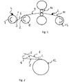
figure 1 shows schematically some working steps of a rolling process of aluminium foils in accordance with the present invention, among which a doubly rolling step of a first aluminium foil and a second aluminium foil; -
figure 2 shows an at least partially wound coupled foil obtained from the afore said doubly rolling step shown infigure 1 , wherein the afore said coupled foil comprises n turns and a second lubricated face, wherein the afore said second lubricated face is an outer face of the afore said coupled foil; -
figure 3 shows an at least partially wound coupled foil comprising an end portion constituted by a respective portion of only one of the afore said first aluminium foil and the afore said second aluminium foil, obtained from a separating step in which, in the afore said coupled foil obtained by the afore said doubly rolling step offigure 2 , one of the afore said first aluminium foil and the afore said second aluminium foil is unwound of one turn, wherein the afore said second lubricated face is a contact face between the afore said first aluminium foil and the afore said second aluminium foil; -
figure 4 shows a further doubly rolling step of the process according to the present invention, subsequent the afore said separating step. - Referring to
figures 1-4 an aluminium foil rolling process according to the present invention is described. - The present process substantially comprises at least two doubly rolling steps, wherein a first aluminium foil denoted with 1, and a second aluminium foil denoted with 2, are coupled rolled, and wherein between the two steps of doubly rolling the first and second aluminium foils remain substantially overlapped one to another, as it will be better evident in the following.
- In detail, the first aluminium foil 1 and the
second aluminium foil 2, each having a respectivefirst face second face 5, 6, where appropriate can be subjected to one or more singly rolling steps, wherein each aluminium foil is individually rolled in order to reduce the initial thickness thereof, such singly rolling steps not being depicted in figures. - Therefore, for a first doubly rolling step between the first aluminium foil 1 and the
second aluminium foil 2, a lubricant denoted with L is inserted. - In particular, a lubricating step (step b) is provided, wherein at least one face of the first face and the second face of at least one aluminium foil between the first aluminium foil and the second aluminium foil is at least partially lubricated, for example by spraying lubricant, thereby obtaining a respective first lubricated face.
- In accordance with the examples of the figures, the
first face 3 of the first aluminium foil 1 is lubricated while the latter is unrolled from a respective first bobbin 7, while thesecond aluminium foil 2 is unrolled from a respective second bobbin 8. - Therefore a coupling step of the first aluminium foil 1 with the
second aluminium foil 2 is provided, also defined as doubling step (step c), wherein the first aluminium foil 1 is overlapped to thesecond aluminium foil 2 so that the first lubricated face, specifically thefirst face 3 of the first aluminium foil 1, is a contact face between the first aluminium foil 1 and thesecond aluminium foil 2. - From the doubling step a coupled foil 9 is obtained and has two outer faces, that is subjected to a rolling step (step d) that causes a reduction of the thickness thereof, for example by a conventional rolling
mill 10. - The rolling step of the coupled foil 9 is also described as doubly rolling.
- In accordance with the invention, the coupled foil 9 is lubricated on at least one of its two outer faces, for example by spraying other lubricant L.
- In particular a lubricating step (step e) is provided, leading to obtain a coupled foil having at least one second lubricated face, in the examples of the figures denoted with 11 on the whole.
- In accordance with the examples of the figures, the lubricating of an outer face of the coupled foil 9 occurs after the doubly rolling step, the possibility of lubricating an outer face of the coupled foil before the doubly rolling step not being however excluded.
- Therefore a winding step (step f) is provided, wherein the coupled foil having a second lubricated
face 11 is rolled up, thereby obtaining a wound coupled foil comprising n turns, denoted with 12. - Substantially the coupled foil having a second lubricated
face 11 is wound n times to form a respective bobbin comprising the afore said n turns. - In accordance with the invention a step of partially separating the wound coupled foil 12 (step g) is provided, wherein one of the first aluminium foil 1 and the
second aluminium foil 2 is unrolled of one turn. - In particular, in accordance with the examples of the figures, in the wound coupled
foil 12 the first aluminium foil 1 is unwound of one turn, therefore of one spiral, i.e. the outermost portion thereof in the afore said bobbin. - A wound coupled foil is therefore obtained, on the whole denoted with 13, comprising an
end portion 14 constituted by a respective portion of only one of the first aluminium foil and the second aluminium foil, in accordance with the examples of the figures such anend portion 14 being constituted by a respective portion of the first aluminium foil 1. - In this way, the lubricant L initially arranged on an outer face of the coupled foil will be interposed between the first and second aluminium foils, the position of the two aluminium foils being reversed in the wound coupled
foil 13 after the unwinding of one turn, which is limited to only one of the aluminium foils. - In accordance with the invention the wound coupled
foil 13 is thus unwound, i.e. unrolled, to be doubly rolled. - In detail, a step of unwinding the wound coupled foil 13 (step h), wherein the afore said second lubricated face is a contact face between the first aluminium foil 1 and the
second aluminium foil 2, and a doubly rolling step (second doubly rolling or step i) of the same coupled foil, wherein the second lubricated face is a contact face between the first aluminium foil 1 and thesecond aluminium foil 2, are therefore provided, thereby obtaining a coupled foil with reduced thickness, denoted with 15 on the whole. - The second rolling step is carried out in a rolling mill of the afore mentioned type, always denoted with 10.
- The coupled
foil 15 with reduced thickness is then separated and a first aluminium foil with a first reduced thickness and a second aluminium foil with a second reduced thickness are obtained and are singularly wound to form respective bobbins, not shown in the figures. - In particular, the coupled
foil 15 with reduced thickness can be separated in the single foils directly after the second doubly rolling, or subsequently after being wound to form arespective bobbin 16. - In practice, in accordance with the invention, a coupled foil can be rolled at least twice without separating one from another the aluminium foils composing the same, still having a lubricant interposed between them, the lubricant being required in order to prevent the aluminium foils from being bound one to another and to be able to separate them at the end of the rolling process.
- In case other doubly rolling steps are desired, the present invention comprises a further lubricating step (step o), wherein at least one outer face of the coupled foil with reduced thickness obtained in the step i) is at least partially lubricated, therefore the carrying out of steps essentially similar to the afore mentioned steps f), g), h) and i) and to which description is referred.
- In regard to the
end portion 14 constituted by a respective portion of only one of the first aluminium foil and the second aluminium foil of the coupled foil, it has to be said that it can be rolled in the second doubly rolling step, or removed from the coupled foil in a dedicated removing step m), for example by cutting the same. - With regard to the afore said step e), it has to be added that it can precede the afore said step d) or be substantially concurrent therewith, as well as it can precede the afore said step f) or be substantially concurrent therewith, the case in which the step e) is comprised between the step d) and the step f) being shown in the examples of figures.
- Again it has to be said that, when required, in step e) and step b) several faces can be lubricated, and precisely both the two outer faces of the coupled foil and, for example, one face per each of the first and second aluminium foils.
- The advantages of the present invention, already appeared evident throughout the present description, can be summarized by pointing out that an aluminium foil rolling process is provided and has increased productivity thanks to the possibility of carrying out several doubly rolling processes, without the need of separating the foils to interpose between them the lubricant needed to separate the aluminium foils at the end of the process.
- In addition to the increased productivity, the present process allows obtaining aluminium foils with particularly reduced thickness.
- In order to meet incidental and specific requirements, several variations and modifications could be made by a field technician to the illustrated and described embodiments of present invention, provided that all are included in the scope of protection of the invention as defined by the following claims.
Claims (10)
- Aluminium foil rolling process comprising the steps of:a) providing at least one first aluminium foil (1) and one second aluminium foil (2) each having a respective first face (3, 4) and a respective second face (5, 6);b) lubricating, at least partially, at least one face between said first face (3, 4) and said second face (5, 6) of at least one aluminium foil between said first aluminium foil (1) and said second aluminium foil (2), thereby obtaining at least one first lubricated face;c) coupling said first aluminium foil (1) with said second aluminium foil, so that said at least one first lubricated face is a contact face between said first aluminium foil and said second aluminium foil, thereby obtaining a coupled foil (9) having two outer faces;d) rolling said coupled foil (9) with reduction of the thickness of said coupled foil;e) lubricating, at least partially, at least one face between said two outer faces of said coupled foil (9), thereby obtaining a coupled foil having at least one second lubricated face (11);f) winding at least partially said coupled foil having at least one second lubricated face (11), obtaining an at least partially wound coupled foil (12) comprising n turns;g) partially separating said at least partially wound coupled foil by unwinding one of said first aluminium foil (1) and said second aluminium foil (2), at least of one turn, thereby obtaining an at least partially wound coupled foil (13) comprising an end portion (14) constituted by a respective portion of only one of said first aluminium foil (1) and said second aluminium foil (2);h) unwinding said at least partially wound coupled foil (13) thereby obtaining a coupled foil wherein said second lubricated face is a contact face between said first aluminium foil (1) and said second aluminium foil (2);i) rolling said coupled foil wherein said second lubricated face is a contact face between said first aluminium foil (1) and said second aluminium foil (2) thereby obtaining a coupled foil (15) with reduced thickness;1) separating said coupled foil (15) with reduced thickness thereby obtaining a first aluminium foil with a first reduced thickness and a second aluminium foil with a second reduced thickness.
- Process according to claim 1, wherein before said step i) a step m) is comprised, wherein said end portion (14) constituted by a respective portion of only one of said first aluminium foil and said second aluminium foil is removed from the coupled foil.
- Process according to claim 1 or 2, wherein said step e) precedes said step d) or is substantially concurrent therewith.
- Process according to claim 1 or 2, wherein said step e) precedes said step f) or is substantially concurrent therewith.
- Process according to any one of the preceding claims, wherein in said step e) both said two outer faces of said coupled foil are lubricated.
- Process according to any one of the preceding claims, wherein in said step b) two faces are lubricated, one face per each of said first aluminium foil (1) and second aluminium foil (2).
- Process according to any one of the preceding claims, wherein between said step a) and said step b) there is at least one step n) of singly rolling, wherein at least one of said first aluminium foil and said second aluminium foil is rolled individually.
- Process according to any one of the preceding claims, comprising a step o) of lubricating, wherein at least one outer face of said coupled foil (15) with reduced thickness, obtained in said step i), is lubricated.
- Process according to claim 8, comprising a further rolling step wherein, before said step 1), said coupled foil with reduced thickness having at least one lubricated outer face obtained in said step o) is rolled.
- Process according to any one of the preceding claims, comprising a winding step, wherein said first aluminium foil with a first reduced thickness and said second aluminium foil with a second reduced thickness both obtained in said step 1) are singularly wound.
Priority Applications (1)
| Application Number | Priority Date | Filing Date | Title |
|---|---|---|---|
| SI201630666T SI3402614T1 (en) | 2016-01-14 | 2016-12-28 | Aluminium foil rolling process |
Applications Claiming Priority (2)
| Application Number | Priority Date | Filing Date | Title |
|---|---|---|---|
| ITUB2016A009972A ITUB20169972A1 (en) | 2016-01-14 | 2016-01-14 | Aluminum foil rolling process |
| PCT/IB2016/058043 WO2017122075A1 (en) | 2016-01-14 | 2016-12-28 | Aluminium foil rolling process |
Publications (2)
| Publication Number | Publication Date |
|---|---|
| EP3402614A1 EP3402614A1 (en) | 2018-11-21 |
| EP3402614B1 true EP3402614B1 (en) | 2020-02-05 |
Family
ID=55795152
Family Applications (1)
| Application Number | Title | Priority Date | Filing Date |
|---|---|---|---|
| EP16829438.7A Active EP3402614B1 (en) | 2016-01-14 | 2016-12-28 | Aluminium foil rolling process |
Country Status (10)
| Country | Link |
|---|---|
| US (1) | US10695808B2 (en) |
| EP (1) | EP3402614B1 (en) |
| KR (1) | KR20180103060A (en) |
| CN (1) | CN108463294B (en) |
| BR (1) | BR112018014386B1 (en) |
| ES (1) | ES2776727T3 (en) |
| IT (1) | ITUB20169972A1 (en) |
| RU (1) | RU2716328C2 (en) |
| SI (1) | SI3402614T1 (en) |
| WO (1) | WO2017122075A1 (en) |
Families Citing this family (1)
| Publication number | Priority date | Publication date | Assignee | Title |
|---|---|---|---|---|
| ITUA20162815A1 (en) * | 2016-04-22 | 2017-10-22 | Guasta Fabrizio | Process for rolling aluminum sheets and aluminum sheets obtained with said process |
Family Cites Families (12)
| Publication number | Priority date | Publication date | Assignee | Title |
|---|---|---|---|---|
| US2529884A (en) * | 1946-06-17 | 1950-11-14 | Reynolds Metals Co | Method of laminating metal foil |
| SU414008A1 (en) * | 1970-07-09 | 1974-02-05 | ||
| JPS577303A (en) * | 1980-06-17 | 1982-01-14 | Showa Alum Corp | Manufacture of aluminum foil for use of reflector |
| DE19511801A1 (en) * | 1995-03-30 | 1996-10-02 | Schloemann Siemag Ag | Method and device for thickness control in film rolling |
| DE19927697A1 (en) * | 1999-06-17 | 2000-12-28 | Vaw Ver Aluminium Werke Ag | Method of manufacturing foils of different thickness by subjecting part of doubled foils to further double rolling pass where doubled foils are separated directly in front of same |
| CA2438703A1 (en) * | 2001-02-22 | 2002-09-06 | Dan Miller | Improved aluminium foil rolling method |
| RU2201821C1 (en) * | 2001-08-29 | 2003-04-10 | ОАО Верхнесалдинское металлургическое производственное объединение | Method for pack rolling of thin sheets of hard-to-form alloys |
| CN1910309A (en) * | 2004-01-09 | 2007-02-07 | 昭和电工株式会社 | Degreasing method of aluminum hard foil, aluminum hard foil, aluminum hard foil electrode material, and lithium ion secondary battery using it |
| DE102006026575A1 (en) * | 2006-03-23 | 2007-09-27 | Hydro Aluminium Deutschland Gmbh | Functional direct coating of an aluminum foil |
| CN101412039B (en) * | 2008-11-21 | 2011-03-30 | 中色科技股份有限公司 | Tridimensional allocation plan of aluminium foil mill |
| US20100242559A1 (en) * | 2009-03-24 | 2010-09-30 | Saenz De Miera Vicente Martin | Method of producing aluminum products |
| CN202070550U (en) * | 2011-03-21 | 2011-12-14 | 杭州五星铝业有限公司 | Aluminum foil mill with oil mist spray-nozzle device |
-
2016
- 2016-01-14 IT ITUB2016A009972A patent/ITUB20169972A1/en unknown
- 2016-12-28 WO PCT/IB2016/058043 patent/WO2017122075A1/en not_active Ceased
- 2016-12-28 US US16/069,338 patent/US10695808B2/en active Active
- 2016-12-28 RU RU2018123989A patent/RU2716328C2/en active
- 2016-12-28 EP EP16829438.7A patent/EP3402614B1/en active Active
- 2016-12-28 ES ES16829438T patent/ES2776727T3/en active Active
- 2016-12-28 SI SI201630666T patent/SI3402614T1/en unknown
- 2016-12-28 KR KR1020187019664A patent/KR20180103060A/en not_active Abandoned
- 2016-12-28 CN CN201680078895.8A patent/CN108463294B/en active Active
- 2016-12-28 BR BR112018014386-3A patent/BR112018014386B1/en active IP Right Grant
Non-Patent Citations (1)
| Title |
|---|
| None * |
Also Published As
| Publication number | Publication date |
|---|---|
| US10695808B2 (en) | 2020-06-30 |
| CN108463294A (en) | 2018-08-28 |
| WO2017122075A1 (en) | 2017-07-20 |
| ITUB20169972A1 (en) | 2017-07-14 |
| EP3402614A1 (en) | 2018-11-21 |
| BR112018014386B1 (en) | 2022-12-06 |
| KR20180103060A (en) | 2018-09-18 |
| BR112018014386A2 (en) | 2018-12-11 |
| RU2018123989A (en) | 2020-02-14 |
| RU2018123989A3 (en) | 2020-02-18 |
| US20190015881A1 (en) | 2019-01-17 |
| SI3402614T1 (en) | 2020-06-30 |
| ES2776727T3 (en) | 2020-07-31 |
| RU2716328C2 (en) | 2020-03-11 |
| CN108463294B (en) | 2020-04-14 |
Similar Documents
| Publication | Publication Date | Title |
|---|---|---|
| DE60317813T2 (en) | METHOD OF MANUFACTURING RAIL MATERIAL ROLLERS AND A WRAPPING MACHINE CONNECTING THE METHOD | |
| EP3402614B1 (en) | Aluminium foil rolling process | |
| US20170174463A1 (en) | Apparatus and Method for Producing Stacks of Partially Overlapping Labels and Roll of Partially Overlapping Labels | |
| US20210335538A1 (en) | Three-dimensional wound iron core, method and device for manufacturing the same by using single-layer amorphous strip | |
| ITTO20060853A1 (en) | MULTIFUNCTIONAL ELECTRIC MECHANISM, BUILT-IN MOUNTING | |
| EP3445505B1 (en) | Process for rolling aluminium foils | |
| RU2015116682A (en) | SMOKING PRODUCT | |
| EP3603469B1 (en) | Production method for coreless paper roll | |
| EP2088106B1 (en) | Coiling machine for winding a web of material | |
| US9530538B2 (en) | Wire harness manufacturing method and wire harness | |
| CA2859884C (en) | Tearing tape for severing a paper web in a papermaking installation | |
| US2774018A (en) | Condensers | |
| CN102862327B (en) | Production process of multi-layer paper | |
| EP3616803B1 (en) | Brake device and method for operating same | |
| JP2010050387A (en) | Method of manufacturing metallized film, metallized film, film material, method of manufacturing film capacitor, and film capacitor | |
| JP2013005628A (en) | Method for manufacturing laminated core, and laminated core manufactured by this method | |
| JP2016043396A (en) | Steel strip manufacturing line and steel strip manufacturing method | |
| JP2014188554A (en) | Method of winding steel strip on reel of reverse rolling machine | |
| EP1657194B1 (en) | Reel winding device and method for winding reels | |
| WO2011069573A1 (en) | System for producing and processing stacks of sheets, in particular stacks of paper sheets | |
| CN205521698U (en) | Film slitting winding mechanism | |
| CN205471863U (en) | Locking winding mechanism that moves of film slitting | |
| CN106064750A (en) | Folding napkin fixing means before cutting and the folding napkin of gained |
Legal Events
| Date | Code | Title | Description |
|---|---|---|---|
| STAA | Information on the status of an ep patent application or granted ep patent |
Free format text: STATUS: UNKNOWN |
|
| STAA | Information on the status of an ep patent application or granted ep patent |
Free format text: STATUS: THE INTERNATIONAL PUBLICATION HAS BEEN MADE |
|
| PUAI | Public reference made under article 153(3) epc to a published international application that has entered the european phase |
Free format text: ORIGINAL CODE: 0009012 |
|
| STAA | Information on the status of an ep patent application or granted ep patent |
Free format text: STATUS: REQUEST FOR EXAMINATION WAS MADE |
|
| 17P | Request for examination filed |
Effective date: 20180710 |
|
| AK | Designated contracting states |
Kind code of ref document: A1 Designated state(s): AL AT BE BG CH CY CZ DE DK EE ES FI FR GB GR HR HU IE IS IT LI LT LU LV MC MK MT NL NO PL PT RO RS SE SI SK SM TR |
|
| AX | Request for extension of the european patent |
Extension state: BA ME |
|
| DAV | Request for validation of the european patent (deleted) | ||
| DAX | Request for extension of the european patent (deleted) | ||
| GRAP | Despatch of communication of intention to grant a patent |
Free format text: ORIGINAL CODE: EPIDOSNIGR1 |
|
| STAA | Information on the status of an ep patent application or granted ep patent |
Free format text: STATUS: GRANT OF PATENT IS INTENDED |
|
| INTG | Intention to grant announced |
Effective date: 20190816 |
|
| RIN1 | Information on inventor provided before grant (corrected) |
Inventor name: BORINELLI, GIOVANNI |
|
| GRAS | Grant fee paid |
Free format text: ORIGINAL CODE: EPIDOSNIGR3 |
|
| GRAA | (expected) grant |
Free format text: ORIGINAL CODE: 0009210 |
|
| STAA | Information on the status of an ep patent application or granted ep patent |
Free format text: STATUS: THE PATENT HAS BEEN GRANTED |
|
| AK | Designated contracting states |
Kind code of ref document: B1 Designated state(s): AL AT BE BG CH CY CZ DE DK EE ES FI FR GB GR HR HU IE IS IT LI LT LU LV MC MK MT NL NO PL PT RO RS SE SI SK SM TR |
|
| REG | Reference to a national code |
Ref country code: GB Ref legal event code: FG4D |
|
| REG | Reference to a national code |
Ref country code: AT Ref legal event code: REF Ref document number: 1229541 Country of ref document: AT Kind code of ref document: T Effective date: 20200215 |
|
| REG | Reference to a national code |
Ref country code: DE Ref legal event code: R096 Ref document number: 602016029264 Country of ref document: DE |
|
| REG | Reference to a national code |
Ref country code: IE Ref legal event code: FG4D |
|
| REG | Reference to a national code |
Ref country code: CH Ref legal event code: EP |
|
| REG | Reference to a national code |
Ref country code: GR Ref legal event code: EP Ref document number: 20200401058 Country of ref document: GR Effective date: 20200615 |
|
| REG | Reference to a national code |
Ref country code: NL Ref legal event code: MP Effective date: 20200205 |
|
| PG25 | Lapsed in a contracting state [announced via postgrant information from national office to epo] |
Ref country code: RS Free format text: LAPSE BECAUSE OF FAILURE TO SUBMIT A TRANSLATION OF THE DESCRIPTION OR TO PAY THE FEE WITHIN THE PRESCRIBED TIME-LIMIT Effective date: 20200205 Ref country code: FI Free format text: LAPSE BECAUSE OF FAILURE TO SUBMIT A TRANSLATION OF THE DESCRIPTION OR TO PAY THE FEE WITHIN THE PRESCRIBED TIME-LIMIT Effective date: 20200205 Ref country code: NO Free format text: LAPSE BECAUSE OF FAILURE TO SUBMIT A TRANSLATION OF THE DESCRIPTION OR TO PAY THE FEE WITHIN THE PRESCRIBED TIME-LIMIT Effective date: 20200505 Ref country code: PT Free format text: LAPSE BECAUSE OF FAILURE TO SUBMIT A TRANSLATION OF THE DESCRIPTION OR TO PAY THE FEE WITHIN THE PRESCRIBED TIME-LIMIT Effective date: 20200628 |
|
| REG | Reference to a national code |
Ref country code: ES Ref legal event code: FG2A Ref document number: 2776727 Country of ref document: ES Kind code of ref document: T3 Effective date: 20200731 |
|
| REG | Reference to a national code |
Ref country code: LT Ref legal event code: MG4D |
|
| PG25 | Lapsed in a contracting state [announced via postgrant information from national office to epo] |
Ref country code: HR Free format text: LAPSE BECAUSE OF FAILURE TO SUBMIT A TRANSLATION OF THE DESCRIPTION OR TO PAY THE FEE WITHIN THE PRESCRIBED TIME-LIMIT Effective date: 20200205 Ref country code: IS Free format text: LAPSE BECAUSE OF FAILURE TO SUBMIT A TRANSLATION OF THE DESCRIPTION OR TO PAY THE FEE WITHIN THE PRESCRIBED TIME-LIMIT Effective date: 20200605 Ref country code: SE Free format text: LAPSE BECAUSE OF FAILURE TO SUBMIT A TRANSLATION OF THE DESCRIPTION OR TO PAY THE FEE WITHIN THE PRESCRIBED TIME-LIMIT Effective date: 20200205 Ref country code: LV Free format text: LAPSE BECAUSE OF FAILURE TO SUBMIT A TRANSLATION OF THE DESCRIPTION OR TO PAY THE FEE WITHIN THE PRESCRIBED TIME-LIMIT Effective date: 20200205 |
|
| PG25 | Lapsed in a contracting state [announced via postgrant information from national office to epo] |
Ref country code: NL Free format text: LAPSE BECAUSE OF FAILURE TO SUBMIT A TRANSLATION OF THE DESCRIPTION OR TO PAY THE FEE WITHIN THE PRESCRIBED TIME-LIMIT Effective date: 20200205 |
|
| PG25 | Lapsed in a contracting state [announced via postgrant information from national office to epo] |
Ref country code: EE Free format text: LAPSE BECAUSE OF FAILURE TO SUBMIT A TRANSLATION OF THE DESCRIPTION OR TO PAY THE FEE WITHIN THE PRESCRIBED TIME-LIMIT Effective date: 20200205 Ref country code: SM Free format text: LAPSE BECAUSE OF FAILURE TO SUBMIT A TRANSLATION OF THE DESCRIPTION OR TO PAY THE FEE WITHIN THE PRESCRIBED TIME-LIMIT Effective date: 20200205 Ref country code: SK Free format text: LAPSE BECAUSE OF FAILURE TO SUBMIT A TRANSLATION OF THE DESCRIPTION OR TO PAY THE FEE WITHIN THE PRESCRIBED TIME-LIMIT Effective date: 20200205 Ref country code: RO Free format text: LAPSE BECAUSE OF FAILURE TO SUBMIT A TRANSLATION OF THE DESCRIPTION OR TO PAY THE FEE WITHIN THE PRESCRIBED TIME-LIMIT Effective date: 20200205 Ref country code: CZ Free format text: LAPSE BECAUSE OF FAILURE TO SUBMIT A TRANSLATION OF THE DESCRIPTION OR TO PAY THE FEE WITHIN THE PRESCRIBED TIME-LIMIT Effective date: 20200205 Ref country code: LT Free format text: LAPSE BECAUSE OF FAILURE TO SUBMIT A TRANSLATION OF THE DESCRIPTION OR TO PAY THE FEE WITHIN THE PRESCRIBED TIME-LIMIT Effective date: 20200205 Ref country code: DK Free format text: LAPSE BECAUSE OF FAILURE TO SUBMIT A TRANSLATION OF THE DESCRIPTION OR TO PAY THE FEE WITHIN THE PRESCRIBED TIME-LIMIT Effective date: 20200205 |
|
| REG | Reference to a national code |
Ref country code: DE Ref legal event code: R097 Ref document number: 602016029264 Country of ref document: DE |
|
| PLBE | No opposition filed within time limit |
Free format text: ORIGINAL CODE: 0009261 |
|
| STAA | Information on the status of an ep patent application or granted ep patent |
Free format text: STATUS: NO OPPOSITION FILED WITHIN TIME LIMIT |
|
| 26N | No opposition filed |
Effective date: 20201106 |
|
| PG25 | Lapsed in a contracting state [announced via postgrant information from national office to epo] |
Ref country code: PL Free format text: LAPSE BECAUSE OF FAILURE TO SUBMIT A TRANSLATION OF THE DESCRIPTION OR TO PAY THE FEE WITHIN THE PRESCRIBED TIME-LIMIT Effective date: 20200205 |
|
| REG | Reference to a national code |
Ref country code: CH Ref legal event code: PL |
|
| GBPC | Gb: european patent ceased through non-payment of renewal fee |
Effective date: 20201228 |
|
| PG25 | Lapsed in a contracting state [announced via postgrant information from national office to epo] |
Ref country code: MC Free format text: LAPSE BECAUSE OF FAILURE TO SUBMIT A TRANSLATION OF THE DESCRIPTION OR TO PAY THE FEE WITHIN THE PRESCRIBED TIME-LIMIT Effective date: 20200205 |
|
| REG | Reference to a national code |
Ref country code: BE Ref legal event code: MM Effective date: 20201231 |
|
| PG25 | Lapsed in a contracting state [announced via postgrant information from national office to epo] |
Ref country code: IE Free format text: LAPSE BECAUSE OF NON-PAYMENT OF DUE FEES Effective date: 20201228 |
|
| PG25 | Lapsed in a contracting state [announced via postgrant information from national office to epo] |
Ref country code: CH Free format text: LAPSE BECAUSE OF NON-PAYMENT OF DUE FEES Effective date: 20201231 Ref country code: LI Free format text: LAPSE BECAUSE OF NON-PAYMENT OF DUE FEES Effective date: 20201231 Ref country code: GB Free format text: LAPSE BECAUSE OF NON-PAYMENT OF DUE FEES Effective date: 20201228 |
|
| REG | Reference to a national code |
Ref country code: AT Ref legal event code: UEP Ref document number: 1229541 Country of ref document: AT Kind code of ref document: T Effective date: 20200205 |
|
| PG25 | Lapsed in a contracting state [announced via postgrant information from national office to epo] |
Ref country code: TR Free format text: LAPSE BECAUSE OF FAILURE TO SUBMIT A TRANSLATION OF THE DESCRIPTION OR TO PAY THE FEE WITHIN THE PRESCRIBED TIME-LIMIT Effective date: 20200205 Ref country code: MT Free format text: LAPSE BECAUSE OF FAILURE TO SUBMIT A TRANSLATION OF THE DESCRIPTION OR TO PAY THE FEE WITHIN THE PRESCRIBED TIME-LIMIT Effective date: 20200205 Ref country code: CY Free format text: LAPSE BECAUSE OF FAILURE TO SUBMIT A TRANSLATION OF THE DESCRIPTION OR TO PAY THE FEE WITHIN THE PRESCRIBED TIME-LIMIT Effective date: 20200205 |
|
| PG25 | Lapsed in a contracting state [announced via postgrant information from national office to epo] |
Ref country code: MK Free format text: LAPSE BECAUSE OF FAILURE TO SUBMIT A TRANSLATION OF THE DESCRIPTION OR TO PAY THE FEE WITHIN THE PRESCRIBED TIME-LIMIT Effective date: 20200205 Ref country code: AL Free format text: LAPSE BECAUSE OF FAILURE TO SUBMIT A TRANSLATION OF THE DESCRIPTION OR TO PAY THE FEE WITHIN THE PRESCRIBED TIME-LIMIT Effective date: 20200205 |
|
| PG25 | Lapsed in a contracting state [announced via postgrant information from national office to epo] |
Ref country code: BE Free format text: LAPSE BECAUSE OF NON-PAYMENT OF DUE FEES Effective date: 20201231 |
|
| P01 | Opt-out of the competence of the unified patent court (upc) registered |
Effective date: 20230413 |
|
| PGFP | Annual fee paid to national office [announced via postgrant information from national office to epo] |
Ref country code: GR Payment date: 20241125 Year of fee payment: 9 |
|
| PGFP | Annual fee paid to national office [announced via postgrant information from national office to epo] |
Ref country code: FR Payment date: 20241111 Year of fee payment: 9 |
|
| PGFP | Annual fee paid to national office [announced via postgrant information from national office to epo] |
Ref country code: AT Payment date: 20241125 Year of fee payment: 9 |
|
| PGFP | Annual fee paid to national office [announced via postgrant information from national office to epo] |
Ref country code: ES Payment date: 20250116 Year of fee payment: 9 |
|
| PGFP | Annual fee paid to national office [announced via postgrant information from national office to epo] |
Ref country code: LU Payment date: 20251112 Year of fee payment: 10 |
|
| PGFP | Annual fee paid to national office [announced via postgrant information from national office to epo] |
Ref country code: DE Payment date: 20251118 Year of fee payment: 10 |
|
| PGFP | Annual fee paid to national office [announced via postgrant information from national office to epo] |
Ref country code: IT Payment date: 20251216 Year of fee payment: 10 |
|
| PGFP | Annual fee paid to national office [announced via postgrant information from national office to epo] |
Ref country code: BG Payment date: 20251111 Year of fee payment: 10 |
|
| PGFP | Annual fee paid to national office [announced via postgrant information from national office to epo] |
Ref country code: SI Payment date: 20251113 Year of fee payment: 10 |