EP3401699A1 - Vehicle environmental detection system for parking detection - Google Patents
Vehicle environmental detection system for parking detection Download PDFInfo
- Publication number
- EP3401699A1 EP3401699A1 EP17170048.7A EP17170048A EP3401699A1 EP 3401699 A1 EP3401699 A1 EP 3401699A1 EP 17170048 A EP17170048 A EP 17170048A EP 3401699 A1 EP3401699 A1 EP 3401699A1
- Authority
- EP
- European Patent Office
- Prior art keywords
- row
- cluster
- arrangement
- border lines
- parking
- Prior art date
- Legal status (The legal status is an assumption and is not a legal conclusion. Google has not performed a legal analysis and makes no representation as to the accuracy of the status listed.)
- Pending
Links
Images


Classifications
-
- B—PERFORMING OPERATIONS; TRANSPORTING
- B60—VEHICLES IN GENERAL
- B60W—CONJOINT CONTROL OF VEHICLE SUB-UNITS OF DIFFERENT TYPE OR DIFFERENT FUNCTION; CONTROL SYSTEMS SPECIALLY ADAPTED FOR HYBRID VEHICLES; ROAD VEHICLE DRIVE CONTROL SYSTEMS FOR PURPOSES NOT RELATED TO THE CONTROL OF A PARTICULAR SUB-UNIT
- B60W30/00—Purposes of road vehicle drive control systems not related to the control of a particular sub-unit, e.g. of systems using conjoint control of vehicle sub-units
- B60W30/06—Automatic manoeuvring for parking
-
- G—PHYSICS
- G01—MEASURING; TESTING
- G01S—RADIO DIRECTION-FINDING; RADIO NAVIGATION; DETERMINING DISTANCE OR VELOCITY BY USE OF RADIO WAVES; LOCATING OR PRESENCE-DETECTING BY USE OF THE REFLECTION OR RERADIATION OF RADIO WAVES; ANALOGOUS ARRANGEMENTS USING OTHER WAVES
- G01S13/00—Systems using the reflection or reradiation of radio waves, e.g. radar systems; Analogous systems using reflection or reradiation of waves whose nature or wavelength is irrelevant or unspecified
- G01S13/88—Radar or analogous systems specially adapted for specific applications
- G01S13/93—Radar or analogous systems specially adapted for specific applications for anti-collision purposes
- G01S13/931—Radar or analogous systems specially adapted for specific applications for anti-collision purposes of land vehicles
-
- B—PERFORMING OPERATIONS; TRANSPORTING
- B60—VEHICLES IN GENERAL
- B60W—CONJOINT CONTROL OF VEHICLE SUB-UNITS OF DIFFERENT TYPE OR DIFFERENT FUNCTION; CONTROL SYSTEMS SPECIALLY ADAPTED FOR HYBRID VEHICLES; ROAD VEHICLE DRIVE CONTROL SYSTEMS FOR PURPOSES NOT RELATED TO THE CONTROL OF A PARTICULAR SUB-UNIT
- B60W60/00—Drive control systems specially adapted for autonomous road vehicles
- B60W60/001—Planning or execution of driving tasks
- B60W60/0025—Planning or execution of driving tasks specially adapted for specific operations
-
- B—PERFORMING OPERATIONS; TRANSPORTING
- B60—VEHICLES IN GENERAL
- B60W—CONJOINT CONTROL OF VEHICLE SUB-UNITS OF DIFFERENT TYPE OR DIFFERENT FUNCTION; CONTROL SYSTEMS SPECIALLY ADAPTED FOR HYBRID VEHICLES; ROAD VEHICLE DRIVE CONTROL SYSTEMS FOR PURPOSES NOT RELATED TO THE CONTROL OF A PARTICULAR SUB-UNIT
- B60W2420/00—Indexing codes relating to the type of sensors based on the principle of their operation
- B60W2420/40—Photo, light or radio wave sensitive means, e.g. infrared sensors
- B60W2420/408—Radar; Laser, e.g. lidar
-
- B—PERFORMING OPERATIONS; TRANSPORTING
- B60—VEHICLES IN GENERAL
- B60W—CONJOINT CONTROL OF VEHICLE SUB-UNITS OF DIFFERENT TYPE OR DIFFERENT FUNCTION; CONTROL SYSTEMS SPECIALLY ADAPTED FOR HYBRID VEHICLES; ROAD VEHICLE DRIVE CONTROL SYSTEMS FOR PURPOSES NOT RELATED TO THE CONTROL OF A PARTICULAR SUB-UNIT
- B60W2554/00—Input parameters relating to objects
- B60W2554/20—Static objects
-
- G—PHYSICS
- G01—MEASURING; TESTING
- G01S—RADIO DIRECTION-FINDING; RADIO NAVIGATION; DETERMINING DISTANCE OR VELOCITY BY USE OF RADIO WAVES; LOCATING OR PRESENCE-DETECTING BY USE OF THE REFLECTION OR RERADIATION OF RADIO WAVES; ANALOGOUS ARRANGEMENTS USING OTHER WAVES
- G01S13/00—Systems using the reflection or reradiation of radio waves, e.g. radar systems; Analogous systems using reflection or reradiation of waves whose nature or wavelength is irrelevant or unspecified
- G01S13/88—Radar or analogous systems specially adapted for specific applications
- G01S13/89—Radar or analogous systems specially adapted for specific applications for mapping or imaging
- G01S13/90—Radar or analogous systems specially adapted for specific applications for mapping or imaging using synthetic aperture techniques, e.g. synthetic aperture radar [SAR] techniques
- G01S13/904—SAR modes
- G01S13/9047—Doppler beam sharpening mode
-
- G—PHYSICS
- G01—MEASURING; TESTING
- G01S—RADIO DIRECTION-FINDING; RADIO NAVIGATION; DETERMINING DISTANCE OR VELOCITY BY USE OF RADIO WAVES; LOCATING OR PRESENCE-DETECTING BY USE OF THE REFLECTION OR RERADIATION OF RADIO WAVES; ANALOGOUS ARRANGEMENTS USING OTHER WAVES
- G01S13/00—Systems using the reflection or reradiation of radio waves, e.g. radar systems; Analogous systems using reflection or reradiation of waves whose nature or wavelength is irrelevant or unspecified
- G01S13/88—Radar or analogous systems specially adapted for specific applications
- G01S13/93—Radar or analogous systems specially adapted for specific applications for anti-collision purposes
- G01S13/931—Radar or analogous systems specially adapted for specific applications for anti-collision purposes of land vehicles
- G01S2013/9314—Parking operations
Definitions
- the ego vehicle 1 does not have to be moving, but can be motionless.
- the vehicle radar system 3 can be constituted by any type of suitable vehicle environmental detection system such as for example Lidar.
- a vehicle environmental detection system 3 can comprises at least one detector arrangement 4, 7 at any suitable corresponding position at the vehicle, and at least one control unit arrangement 15. Said detector arrangement 4, 7 is adapted to obtain a plurality of detections 14.
Landscapes
- Engineering & Computer Science (AREA)
- Remote Sensing (AREA)
- Radar, Positioning & Navigation (AREA)
- Physics & Mathematics (AREA)
- Mechanical Engineering (AREA)
- Automation & Control Theory (AREA)
- Transportation (AREA)
- Computer Networks & Wireless Communication (AREA)
- General Physics & Mathematics (AREA)
- Electromagnetism (AREA)
- Human Computer Interaction (AREA)
- Traffic Control Systems (AREA)
- Radar Systems Or Details Thereof (AREA)
Abstract
- Form a cluster (40) of said plurality of detections (14).
- Form a first border line (16) and a second border line (17), where these border lines (16, 17) have mutually longitudinal extensions, are mutually parallel and define outer borders of the cluster (40).
- Determine whether the cluster (40) corresponds to a row (13) of corresponding parked vehicles (18a, 18b, 18c, 18d, 18e, 18f, 18g), a parking row (13), by means of the length and/or longitudinal displacement of, and/or distance between, the border lines (16, 17).
Description
- The present disclosure relates to a vehicle environmental detection system arranged to be mounted in an ego vehicle and comprising at least one detector arrangement and at least one control unit arrangement.
- Today, one or more radar systems as well as other vehicle environmental detection systems such as for example Lidar (Light detection and ranging) and camera images, are often used in vehicles in order to detect obstacles in the surroundings. Such a radar system is usually arranged to distinguish or resolve single targets from the surroundings by using a Doppler effect in a previously well-known manner.
- Apart from use for collision detector arrangements, radars as well as other vehicle environmental detection systems may for example be used for detecting available space for parking spots and assisting when parking a vehicle. When detecting available space for parking, a row of parked cars has to be automatically identified.
- A method for assisting a driver of a vehicle during a parking operation is described in
EP 2557020 . Environmental data characterizing the environment of the vehicle are provided and evaluated with respect to at least one first object in a lateral environment and at least one second object outside said lateral environment. - However, a more efficient and uncomplicated method and device for detecting available space for parking spots is desired.
- The object of the present disclosure is thus to provide a vehicle environmental detection system arranged for detecting available space for parking spots in more efficient and uncomplicated manner than as disclosed in prior art.
- Said object is achieved by means of a vehicle environmental detection system arranged to be mounted in an ego vehicle and comprising at least one detector arrangement and at least one control unit arrangement. The detector arrangement is adapted to obtain a plurality of detections. The control unit arrangement is adapted to form a cluster of said plurality of detections, and to form a first border line and a second border line. These border lines have mutually longitudinal extensions, are mutually parallel and define outer borders of the cluster. The control unit arrangement is further adapted to determine whether the cluster corresponds to a row of corresponding parked vehicles, a parking row, by means of the length and/or longitudinal displacement of, and/or distance between, the border lines.
- Said object is also achieved by means of a method for a vehicle environmental detection system in an ego vehicle. The method comprises obtaining a plurality of detections, forming a cluster of said plurality of detections, and forming a first border line and a second border line. These border lines have mutually longitudinal extensions, are mutually parallel and define outer borders of the cluster. The method further comprises determining whether the cluster corresponds to a row of corresponding parked vehicles, a parking row, using the length and/or longitudinal displacement of, and/or distance between, the border lines.
- According to some aspects, if the cluster has been determined to constitute a row of corresponding parked vehicles in the parking row, the control unit arrangement is adapted to determine how at least one connection line, arranged to connect the border lines, is running with respect to the border lines, and to determine a shortest distance between the border lines. the control unit arrangement is then further adapted to compare said distance with a predetermined vehicle width and a predetermined vehicle length, and to determine how the vehicles in the parking row are oriented with respect to a movement direction of the vehicle environmental detection system.
- According to some aspects, if the cluster has been determined to constitute a row of corresponding parked vehicles in the parking row, the control unit arrangement is adapted to determine gaps in detections between the two border lines in order to determine available parking spots.
- Other aspects of the present disclosure are disclosed in the dependent claims.
- A number of advantages are obtained by means of the present disclosure. For example:
- Parking rows are easily detected even though partly covered or merged with road borders like close buildings.
- No reference is needed, i.e. parking rows can be detected on free fields or in free space.
- Detection is independent of the ego vehicle's movement direction.
- Detection is independent of the number of occupied parking spots.
- Detection is independent of the ego vehicle's velocity.
- Provides main characteristics of a parking row, i.e. orientation of the parked cars.
- Enables a fast, uncomplicated and robust detection.
- The present disclosure will now be described more in detail with reference to the appended drawings, where:
- Figure 1
- shows a schematic side view of a vehicle;
- Figure 2
- shows a simplified schematic of a radar system according to the present disclosure;
- Figure 3
- shows a schematic top view of a vehicle passing a parking row according to a first example;
- Figure 4
- shows a schematic top view of radar detections being grouped into a cluster;
- Figure 5
- shows a simplified schematic top view of a vehicle passing a parking row according to a second example;
- Figure 6
- shows a simplified schematic top view of a vehicle passing a parking row according to a third example; and
- Figure 7
- shows a flowchart for a method according to the present disclosure.
-
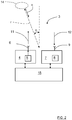
Figure 1 schematically shows a side view anego vehicle 1 that runs on aroad 2 in a movement direction F, where thevehicle 1 comprises avehicle radar system 3 which is arranged to distinguish and/or resolve single targets from the surroundings by using a Doppler effect together with analysis of received reflected signals in a previously well-known manner, i.e. successive echoes from the same point are superimposed and identified by means of Doppler effect. The radar system is positioned on the right-hand side of the vehicle, and has a main field ofview 10 that is aimed in a pointing direction P that extends more or less perpendicular to the movement direction F. According to some aspects, the main field ofview 10 has an azimuth angel of about 140°. - With reference also to
Figure 2 , theradar system 3 comprises atransmitter arrangement 4 which in turn comprises asignal generator 5 and atransmitter antenna arrangement 6. Thevehicle radar system 3 further comprises areceiver arrangement 7, which in turn comprises areceiver 8 and areceiver antenna arrangement 9. - Transmitted
signals 11 are reflected, and thereflected signals 12 are received by thereceiver 8 via thereceiver antenna arrangement 9. When in use, thetransmitter antenna arrangement 6 sends a signal in the pointing direction P when theego vehicle 1 runs past aparking 13, theradar system 3 having said certain field ofview 10 that passes along theparking 13. Theradar system 3 then receives echoes of the transmittedsignals 11 by means of thereceiver antenna arrangement 8. The field ofview 10 corresponds to the beamwidth of theantenna arrangements - With reference also to
Figure 3 , the above is repeated as many times as necessary at a predetermined frequency band, while theego vehicle 1 moves in the movement direction F, to obtain a plurality ofradar detections 14. - The
receiver arrangement 7 provides filtered IF (Intermediate Frequency) signals converted to digital signals to acontrol unit arrangement 15 comprising a DSP (Digital Signal Processor) functionality that is adapted for radar signal processing by means of a first FFT (Fast Fourier Transform) to convert the digital signals to a range domain, and a second FFT to combine the results from successive radar cycles into the Doppler domain in a previously well-known manner. - The
control unit arrangement 15 is thus arranged to provide azimuth angles of possible target objects by simultaneously sampling and analyzing phase and amplitude of the receivedsignals 12. Each radar detection has a certain detected azimuth angle α, distance r and radial velocity v as schematically indicated inFigure 2 . - According to the present disclosure, with reference also to
Figure 4 , thecontrol unit arrangement 15 also comprises a clustering functionality and is adapted to group theradar detections 14 into acluster 40 in a clustering procedure. Generally, a cluster corresponds to a structure such as a parking row, or in which a parking row is included; e.g. a wall of a house and/or a parallel existing parking row. - By means of the formed
cluster 40, thecontrol unit arrangement 15 is further adapted to form afirst border line 16 and asecond border line 17, where theseborder lines cluster 40. By means of the relation between theborder lines control unit arrangement 15 is adapted to determine whether the formedcluster 40 comprises arow 13 of correspondingparked vehicles parking row 13, and how thesevehicles parking row 13. This is according to some aspects determined by means of analysis of length and/or longitudinal displacement of, and/or distance between theborder lines 16, and how these are related. This will be described more in detail in the following. - The
control unit arrangement 15 is adapted to form thecluster 40 means of known algorithms, e.g. a DBSCAN (Density-based spatial clustering of applications with noise) method, and determine theborder lines - The
first border line 16 is a representation of radar detections caused by parkedvehicles parking row 13. Thesecond border line 17 is a representation of radar detections caused by the limitation of the parking row, e.g. environmental objects such as curb,wall 20, hedgerow etc. or rims and/or other vehicle parts at the backside of the parkedvehicles parking row 13. - In a further step, the
control unit arrangement 15 is adapted to determinegaps border lines ego vehicle 1, where the orientation of theparking row 13 and distance to theego car 1 are known. - The
control unit arrangement 15 is also adapted to determine the characteristics of the detected parking row by analyzing theborder lines - The
cluster 40 according to the first example inFigure 4 has afirst border line 16 and asecond border line 17 that run parallel and are connected by a first connectingline 21a and a second connectingline 21b, which connectinglines border lines shortest distance 22 between theborder lines vehicles border lines - A
parking row 23 according to second example, with reference toFigure 5 , has afirst border line 24 and asecond border line 25 that run parallel and are connected by a first connecting line 26a and a second connecting line 26b. The first connecting line 26a runs at a first angle ϕ to theborder line 24 closest to theego vehicle 1 that falls below 90°. The second connecting line 26b runs at a second angle θ to theborder line 24 closest to theego vehicle 1 that exceeds 90°. It is thus determined that these angles ϕ, θ differ from 90°. - By also determining a
shortest distance 27 between theborder lines vehicles border lines ego vehicle 1 approaches thecluster 40. - A
parking row 29 according to third example, with reference toFigure 6 , has afirst border line 30 and asecond border line 31 that run parallel and are connected by a first connecting line 32a and a second connecting line 32b, which connectinglines border lines shortest distance 33 between theborder lines vehicles border lines - By means of this approach, it is determined if it is a row of parked vehicles that is detected, and if that is the case, the characteristics of the parking row. Then it is determined whether there are any available parking spots.
- For reasons of clarity, only a
few radar detections 14 are shown inFigure 3 , and no radar detections are shown inFigure 5 andFigure 6 . Of course, practically, there is a multitude of radar detections. According to some aspects, the detections from a radar cycle are saved in a detection memory to the next radar cycle in order to provide a better representation of the environment. - With reference to
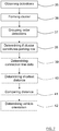
Figure 7 , the present disclosure also relates to a method for a vehicleenvironmental detection system 3 in anego vehicle 1. The method comprises: - 35: Obtaining a plurality of
detections 14. - 36: Forming a
cluster 40 of said plurality ofdetections 14. - 37: Forming a
first border line 16 and asecond border line 17, where theseborder lines cluster 40. - 38: Determining whether the
cluster 40 corresponds to arow 13 of corresponding parkedvehicles parking row 13, using the length and/or longitudinal displacement of, and/or distance between, theborder lines - According to some aspects, if the
cluster 40 has been determined to constitute arow 13 of corresponding parkedvehicles parking row - 39: Determining how at least one
connection line border lines border lines - 40: Determining a
shortest distance border lines - 41: Comparing said distance with a predetermined vehicle width and a predetermined vehicle length.
- 42: Determining how the
vehicles parking row environmental detection system 3. - The present disclosure is not limited to the examples above, but may vary freely within the scope of the appended claims. For example, the radar system may be implemented in any type of vehicle such as cars, trucks and buses as well as boats and aircraft.
- All drawings are simplified, only showing parts that are considered relevant for an adequate description of the present disclosure. It is understood that the general design of radar systems of this kind is well-known in the art.
- The constitution of the antennas comprised in the
transmitter antenna arrangement 6 andreceiver antenna arrangement 9 may be of any suitable design, such as slot antennas of patch antennas. Thetransmitter antenna arrangement 6 andreceiver antenna arrangement 9 may be combined in one antenna arrangement that is arranged for both transmission and reception by means of, for example, time division. - Terms such as perpendicular and parallel are not to be interpreted as mathematically exact, but within what is practical in the present context. The border lines have mutually longitudinal extensions and are mutually parallel, but of course smaller deviations can occur due to practical reasons.
- According to some aspects, the
control unit arrangement 15, comprises one or several separate control units that are arranged together or in a distributed manner. - According to some aspects, the
ego vehicle 1 does not have to be moving, but can be motionless. - According to some aspects, the
vehicle radar system 3 can be constituted by any type of suitable vehicle environmental detection system such as for example Lidar. Such a vehicleenvironmental detection system 3 can comprises at least onedetector arrangement control unit arrangement 15. Saiddetector arrangement detections 14. - The movement direction F can be directed in a forward movement direction as well as in a rearward movement direction.
- According to some aspects, the
ego vehicle 1 can approach the parking row from any angle; each approaching angle is possible as long as the parking row is in the field of view of theradar system 3 or in a detection memory. - Generally, the present disclosure relates to a vehicle
environmental detection system 3 arranged to be mounted in anego vehicle 1 and comprising at least onedetector arrangement control unit arrangement 15, where saiddetector arrangement detections 14. Thecontrol unit arrangement 15 is adapted to: - form a
cluster 40 of said plurality ofdetections 14; - form a
first border line 16 and asecond border line 17, where theseborder lines cluster 40; and to - determine whether the
cluster 40 corresponds to arow 13 of corresponding parkedvehicles parking row 13, by means of the length and/or longitudinal displacement of, and/or distance between, theborder lines - According to some aspects, the vehicle environmental detection system is constituted by a
radar system 3, where said detector arrangement comprises atransmitter arrangement 4 and areceiver arrangement 7, where thetransmitter arrangement 4 comprises asignal generator 5 and atransmitter antenna arrangement 6 arranged for transmittingsignals 11, and where thereceiver arrangement 7 comprises areceiver 8 and areceiver antenna arrangement 9 arranged for receiving reflected signals 12. - According to some aspects, if the
cluster 40 has been determined to constitute arow 13 of corresponding parkedvehicles parking row control unit arrangement 15 is adapted to: - determine how at least one
connection line border lines border lines - determine a
shortest distance border lines - compare said distance with a predetermined vehicle width and a predetermined vehicle length; and to
- determine how the
vehicles parking row environmental detection system 3. - According to some aspects, if the
cluster 40 has been determined to constitute arow 13 of corresponding parkedvehicles parking row control unit arrangement 15 is adapted to determinegaps border lines - Generally, the present disclosure also relates to a method for a vehicle
environmental detection system 3 in anego vehicle 1, where the method comprises: - 35: obtaining a plurality of
detections 14. - 36: forming a
cluster 40 of said plurality ofdetections 14; - 37: forming a
first border line 16 and asecond border line 17, where theseborder lines cluster 40; and - 38: determining whether the
cluster 40 corresponds to arow 13 of corresponding parkedvehicles parking row 13, using the length and/or longitudinal displacement of, and/or distance between, theborder lines - According to some aspects, if the
cluster 40 has been determined to constitute arow 13 of corresponding parkedvehicles parking row - 39: determining how at least one
connection line border lines border lines - 40: determining a
shortest distance border lines - 41: comparing said distance with a predetermined vehicle width and a predetermined vehicle length; and
- 42: determining how the
vehicles parking row environmental detection system 3. - According to some aspects, if the
cluster 40 has been determined to constitute arow 13 of corresponding parkedvehicles parking row gaps border lines
Claims (7)
- A vehicle environmental detection system (3) arranged to be mounted in an ego vehicle (1) and comprising at least one detector arrangement (4, 7) and at least one control unit arrangement (15), where said detector arrangement (4, 7) is adapted to obtain a plurality of detections (14), characterized in that the control unit arrangement (15) is adapted to:- form a cluster (40) of said plurality of detections (14);- form a first border line (16) and a second border line (17), where these border lines (16, 17) have mutually longitudinal extensions, are mutually parallel and define outer borders of the cluster (40); and to- determine whether the cluster (40) corresponds to a row (13) of corresponding parked vehicles (18a, 18b, 18c, 18d, 18e, 18f, 18g), a parking row (13), by means of the length and/or longitudinal displacement of, and/or distance between, the border lines (16, 17).
- The vehicle environmental detection system (3) according to claim 1, characterized in that the vehicle environmental detection system is constituted by a radar system (3), where said detector arrangement comprises a transmitter arrangement (4) and a receiver arrangement (7), where the transmitter arrangement (4) comprises a signal generator (5) and a transmitter antenna arrangement (6) arranged for transmitting signals (11), and where the receiver arrangement (7) comprises a receiver (8) and a receiver antenna arrangement (9) arranged for receiving reflected signals (12).
- The vehicle environmental detection system (3) according to any one of the claims 1 or 2, characterized in that if the cluster (40) has been determined to constitute a row (13) of corresponding parked vehicles (18a, 18b, 18c, 18d, 18e, 18f, 18g; 28a, 28b, 28c, 28d, 28e, 28f, 28g; 34a, 34b, 34c, 34d) in the parking row (13, 23, 29), the control unit arrangement (15) is adapted to:determine how at least one connection line (13, 26, 32), arranged to connect the border lines (16, 17; 24, 25; 30, 31), is running with respect to the border lines (16, 17; 24, 25; 30, 31);determine a shortest distance (22, 27, 33) between the border lines (16, 17; 24, 25; 30, 31);compare said distance with a predetermined vehicle width and a predetermined vehicle length; and todetermine how the vehicles (18a, 18b, 18c, 18d, 18e, 18f, 18g; 28a, 28b, 28c, 28d, 28e, 28f, 28g; 34a, 34b, 34c, 34d) in the parking row (13, 23, 29) are oriented with respect to a movement direction (F) of the vehicle environmental detection system (3).
- The radar system according to any one of the preceding claims, characterized in that if the cluster (40) has been determined to constitute a row (13) of corresponding parked vehicles (18a, 18b, 18c, 18d, 18e, 18f, 18g; 28a, 28b, 28c, 28d, 28e, 28f, 28g; 34a, 34b, 34c, 34d) in the parking row (13, 23, 29), the control unit arrangement (15) is adapted to determine gaps (19a, 19b) in detections between the two border lines (16, 17; 24, 25; 30, 31) in order to determine available parking spots.
- A method for a vehicle environmental detection system (3) in an ego vehicle (1), where the method comprises:(35) obtaining a plurality of detections (14), characterized in that the method further comprises:(36) forming a cluster (40) of said plurality of detections (14) ;(37) forming a first border line (16) and a second border line (17), where these border lines (16, 17) have mutually longitudinal extensions, are mutually parallel and define outer borders of the cluster (40); and(38) determining whether the cluster (40) corresponds to a row (13) of corresponding parked vehicles (18a, 18b, 18c, 18d, 18e, 18f, 18g), a parking row (13), using the length and/or longitudinal displacement of, and/or distance between, the border lines (16, 17).
- The method according to claim 5, characterized in that the if the cluster (40) has been determined to constitute a row (13) of corresponding parked vehicles (18a, 18b, 18c, 18d, 18e, 18f, 18g; 28a, 28b, 28c, 28d, 28e, 28f, 28g; 34a, 34b, 34c, 34d) in the parking row (13, 23, 29), the method comprises:(39) determining how at least one connection line (13, 26, 32), arranged to connect the border lines (16, 17; 24, 25; 30, 31), is running with respect to the border lines (16, 17; 24, 25; 30, 31);(40) determining a shortest distance (22, 27, 33) between the border lines (16, 17; 24, 25; 30, 31);(41) comparing said distance with a predetermined vehicle width and a predetermined vehicle length; and(42) determining how the vehicles (18a, 18b, 18c, 18d, 18e, 18f, 18g; 28a, 28b, 28c, 28d, 28e, 28f, 28g; 34a, 34b, 34c, 34d) in the parking row (13, 23, 29) are oriented with respect to a movement direction (F) of the vehicle environmental detection system (3).
- The method according to any one of the claims 5 or 6, characterized in that if the cluster (40) has been determined to constitute a row (13) of corresponding parked vehicles (18a, 18b, 18c, 18d, 18e, 18f, 18g; 28a, 28b, 28c, 28d, 28e, 28f, 28g; 34a, 34b, 34c, 34d) in the parking row (13, 23, 29), the method comprises determining gaps (19a, 19b) in detections between the two border lines (16, 17; 24, 25; 30, 31) in order to determine available parking spots.
Priority Applications (4)
| Application Number | Priority Date | Filing Date | Title |
|---|---|---|---|
| EP17170048.7A EP3401699A1 (en) | 2017-05-09 | 2017-05-09 | Vehicle environmental detection system for parking detection |
| US16/607,273 US11180137B2 (en) | 2017-05-09 | 2018-05-04 | Vehicle environmental detection system for parking detection |
| CN201880030090.5A CN110603460B (en) | 2017-05-09 | 2018-05-04 | Vehicle environment detection system for parking detection |
| PCT/EP2018/061500 WO2018206426A1 (en) | 2017-05-09 | 2018-05-04 | Vehicle environmental detection system for parking detection |
Applications Claiming Priority (1)
| Application Number | Priority Date | Filing Date | Title |
|---|---|---|---|
| EP17170048.7A EP3401699A1 (en) | 2017-05-09 | 2017-05-09 | Vehicle environmental detection system for parking detection |
Publications (1)
| Publication Number | Publication Date |
|---|---|
| EP3401699A1 true EP3401699A1 (en) | 2018-11-14 |
Family
ID=58701432
Family Applications (1)
| Application Number | Title | Priority Date | Filing Date |
|---|---|---|---|
| EP17170048.7A Pending EP3401699A1 (en) | 2017-05-09 | 2017-05-09 | Vehicle environmental detection system for parking detection |
Country Status (4)
| Country | Link |
|---|---|
| US (1) | US11180137B2 (en) |
| EP (1) | EP3401699A1 (en) |
| CN (1) | CN110603460B (en) |
| WO (1) | WO2018206426A1 (en) |
Cited By (3)
| Publication number | Priority date | Publication date | Assignee | Title |
|---|---|---|---|---|
| CN116299473A (en) * | 2023-03-31 | 2023-06-23 | 电子科技大学长三角研究院(衢州) | A Method of Crossing Target Detection Based on MIMO Millimeter Wave Radar |
| DE102024201957A1 (en) * | 2024-03-01 | 2025-09-04 | Volkswagen Aktiengesellschaft | Method for detecting objects in a parking space for motor vehicles |
| EP4506226A4 (en) * | 2022-04-07 | 2026-04-15 | Toyota Motor Co Ltd | DRIVING ASSISTANCE DEVICE, DRIVING ASSISTANCE PROCEDURES AND PROGRAM |
Families Citing this family (4)
| Publication number | Priority date | Publication date | Assignee | Title |
|---|---|---|---|---|
| KR102812684B1 (en) * | 2019-07-24 | 2025-05-27 | 현대자동차주식회사 | Vehicle and control method for the same |
| CN111605547B (en) * | 2020-05-20 | 2021-05-18 | 湖北亿咖通科技有限公司 | Automatic parking performance evaluation method |
| CN113362649A (en) * | 2021-06-30 | 2021-09-07 | 安诺(深圳)创新技术有限公司 | Auxiliary driving system based on Internet of vehicles |
| DE102023123291A1 (en) | 2023-08-30 | 2025-03-06 | Bayerische Motoren Werke Aktiengesellschaft | Method and parking assistance device for detecting a parking space for a motor vehicle |
Citations (6)
| Publication number | Priority date | Publication date | Assignee | Title |
|---|---|---|---|---|
| DE102005045260A1 (en) * | 2005-09-22 | 2007-03-29 | Valeo Schalter Und Sensoren Gmbh | Method for measuring parking spaces |
| FR2905765A1 (en) * | 2006-09-07 | 2008-03-14 | Renault Sas | DEVICE AND METHOD FOR ESTIMATING THE DIMENSIONS OF A PARKING PLACE, MOTOR VEHICLE COMPRISING SUCH A DEVICE. |
| EP2557020A2 (en) | 2011-08-12 | 2013-02-13 | Robert Bosch Gmbh | Method to support a driver when parking |
| DE102013103569A1 (en) * | 2012-04-17 | 2013-10-17 | Denso Corporation | Parking detection device |
| EP2881754A1 (en) * | 2013-12-06 | 2015-06-10 | Autoliv Development AB | Vehicle radar for environmental detection |
| DE102015003666A1 (en) * | 2015-03-20 | 2016-09-22 | Daimler Ag | Method for processing acquired measured data of a sensor |
Family Cites Families (19)
| Publication number | Priority date | Publication date | Assignee | Title |
|---|---|---|---|---|
| JP2000264208A (en) * | 1999-03-12 | 2000-09-26 | Toshiba Corp | Vehicle traffic system |
| DE102007009745A1 (en) * | 2007-02-28 | 2008-09-04 | Continental Automotive Gmbh | Method for controlling vehicle steering during parking process, involves measuring parking place selected for parking vehicle and establishing orientation field, where orientation field determines number of support points |
| DE102007045562A1 (en) * | 2007-09-24 | 2009-04-02 | Robert Bosch Gmbh | Control device for a display device of a parking device and method for representation |
| KR101104609B1 (en) * | 2007-10-26 | 2012-01-12 | 주식회사 만도 | Target parking location recognition method of vehicle and its system |
| JP5008529B2 (en) * | 2007-10-31 | 2012-08-22 | 三菱電機株式会社 | Parking assistance device |
| WO2009078356A1 (en) * | 2007-12-18 | 2009-06-25 | Honda Motor Co., Ltd. | Parking availability judging device for vehicle, parking space detector for vehicle and movable range detector for vehicle |
| JP5443886B2 (en) * | 2009-07-31 | 2014-03-19 | クラリオン株式会社 | Parking space recognition device |
| DE102009028251A1 (en) * | 2009-08-05 | 2011-02-10 | Robert Bosch Gmbh | Method for assisting parking in a parking space and device for this purpose |
| US20110068953A1 (en) * | 2009-09-24 | 2011-03-24 | Salvador Toledo | Vehicle Park Assist System and Method for Parking a Vehicle Using Such System |
| CN102085864B (en) * | 2009-12-04 | 2013-07-24 | 财团法人工业技术研究院 | Method for controlling parking of vehicle and system for controlling parking of vehicle |
| CN102372000B (en) * | 2010-08-23 | 2014-02-05 | 北京经纬恒润科技有限公司 | Device and system for acquiring parking lot parameters |
| TWI464085B (en) * | 2011-07-22 | 2014-12-11 | Automotive Res & Testing Ct | Parking space detection method |
| DE102011113916A1 (en) * | 2011-09-21 | 2013-03-21 | Volkswagen Aktiengesellschaft | Method for classifying parking scenarios for a parking system of a motor vehicle |
| JP6167824B2 (en) * | 2013-10-04 | 2017-07-26 | アイシン精機株式会社 | Parking assistance device |
| KR20170041166A (en) * | 2014-01-30 | 2017-04-14 | 유니베르시다데 도 포르토 | Device and method for self-automated parking lot for autonomous vehicles based on vehicular networking |
| JP5843948B1 (en) * | 2014-11-27 | 2016-01-13 | 三菱電機株式会社 | Parking assistance device and parking assistance method |
| US9542845B1 (en) * | 2015-09-11 | 2017-01-10 | Robert Bosch Gmbh | Method for ascertaining a parking area of a street section |
| US10592756B2 (en) * | 2015-09-11 | 2020-03-17 | Robert Bosch Gmbh | Method for detecting a parking area on a road section |
| KR20180047210A (en) * | 2016-10-31 | 2018-05-10 | 현대자동차주식회사 | Apparatus and method for detecting parking slot |
-
2017
- 2017-05-09 EP EP17170048.7A patent/EP3401699A1/en active Pending
-
2018
- 2018-05-04 CN CN201880030090.5A patent/CN110603460B/en active Active
- 2018-05-04 US US16/607,273 patent/US11180137B2/en active Active
- 2018-05-04 WO PCT/EP2018/061500 patent/WO2018206426A1/en not_active Ceased
Patent Citations (6)
| Publication number | Priority date | Publication date | Assignee | Title |
|---|---|---|---|---|
| DE102005045260A1 (en) * | 2005-09-22 | 2007-03-29 | Valeo Schalter Und Sensoren Gmbh | Method for measuring parking spaces |
| FR2905765A1 (en) * | 2006-09-07 | 2008-03-14 | Renault Sas | DEVICE AND METHOD FOR ESTIMATING THE DIMENSIONS OF A PARKING PLACE, MOTOR VEHICLE COMPRISING SUCH A DEVICE. |
| EP2557020A2 (en) | 2011-08-12 | 2013-02-13 | Robert Bosch Gmbh | Method to support a driver when parking |
| DE102013103569A1 (en) * | 2012-04-17 | 2013-10-17 | Denso Corporation | Parking detection device |
| EP2881754A1 (en) * | 2013-12-06 | 2015-06-10 | Autoliv Development AB | Vehicle radar for environmental detection |
| DE102015003666A1 (en) * | 2015-03-20 | 2016-09-22 | Daimler Ag | Method for processing acquired measured data of a sensor |
Cited By (3)
| Publication number | Priority date | Publication date | Assignee | Title |
|---|---|---|---|---|
| EP4506226A4 (en) * | 2022-04-07 | 2026-04-15 | Toyota Motor Co Ltd | DRIVING ASSISTANCE DEVICE, DRIVING ASSISTANCE PROCEDURES AND PROGRAM |
| CN116299473A (en) * | 2023-03-31 | 2023-06-23 | 电子科技大学长三角研究院(衢州) | A Method of Crossing Target Detection Based on MIMO Millimeter Wave Radar |
| DE102024201957A1 (en) * | 2024-03-01 | 2025-09-04 | Volkswagen Aktiengesellschaft | Method for detecting objects in a parking space for motor vehicles |
Also Published As
| Publication number | Publication date |
|---|---|
| CN110603460B (en) | 2023-06-27 |
| US11180137B2 (en) | 2021-11-23 |
| CN110603460A (en) | 2019-12-20 |
| WO2018206426A1 (en) | 2018-11-15 |
| US20200298833A1 (en) | 2020-09-24 |
Similar Documents
| Publication | Publication Date | Title |
|---|---|---|
| US11180137B2 (en) | Vehicle environmental detection system for parking detection | |
| US10018713B2 (en) | Radar system for motor vehicles, and motor vehicle having a radar system | |
| US10473760B2 (en) | Radar device and vertical axis-misalignment detecting method | |
| US11396282B2 (en) | Autonomous emergency braking system and method of controlling same | |
| US20180128916A1 (en) | Object detection in multiple radars | |
| US20160363651A1 (en) | Apparatus for processing signals of radar and method for processing signals thereof | |
| US11614535B2 (en) | Radar apparatus for vehicle and method for controlling the same | |
| CN105093213A (en) | Radar system with improved multi-target discrimination | |
| US10481251B2 (en) | Radar device and target detecting method | |
| JP2019518946A (en) | Radar sensor device for a motor vehicle, driver assistance system, motor vehicle and method for sensing an object | |
| KR20190125453A (en) | Methods and Radar Devices for Determining Radial Relative Acceleration of One or More Targets | |
| US12061285B2 (en) | Detecting a parking row with a vehicle radar system | |
| JP7307244B2 (en) | ELECTRONIC DEVICE, ELECTRONIC DEVICE CONTROL METHOD, AND PROGRAM | |
| CN105103004B (en) | Apparatus and method for determining elevation angle in a radar system | |
| EP3865909B1 (en) | Electronic device, method for controlling electronic device, and program for controlling electronic device | |
| US10754024B2 (en) | Object-sensing system for vehicle and object-sensing method for vehicle | |
| US20180321377A1 (en) | Method for capturing a surrounding region of a motor vehicle with object classification, control device, driver assistance system and motor vehicle | |
| JPWO2007015288A1 (en) | Axis deviation amount estimation method and axis deviation amount estimation device | |
| EP3422046B1 (en) | A system for enhanced object tracking | |
| US11333754B2 (en) | Detection of parking row orientation | |
| CN119620002A (en) | Radar system transmitter beamforming using occupancy map data | |
| EP3422045B1 (en) | A system for enhanced object tracking | |
| KR20160112672A (en) | Apparatus for processing Radar signal and the method thereof |
Legal Events
| Date | Code | Title | Description |
|---|---|---|---|
| PUAI | Public reference made under article 153(3) epc to a published international application that has entered the european phase |
Free format text: ORIGINAL CODE: 0009012 |
|
| STAA | Information on the status of an ep patent application or granted ep patent |
Free format text: STATUS: THE APPLICATION HAS BEEN PUBLISHED |
|
| AK | Designated contracting states |
Kind code of ref document: A1 Designated state(s): AL AT BE BG CH CY CZ DE DK EE ES FI FR GB GR HR HU IE IS IT LI LT LU LV MC MK MT NL NO PL PT RO RS SE SI SK SM TR |
|
| AX | Request for extension of the european patent |
Extension state: BA ME |
|
| STAA | Information on the status of an ep patent application or granted ep patent |
Free format text: STATUS: REQUEST FOR EXAMINATION WAS MADE |
|
| 17P | Request for examination filed |
Effective date: 20190510 |
|
| RBV | Designated contracting states (corrected) |
Designated state(s): AL AT BE BG CH CY CZ DE DK EE ES FI FR GB GR HR HU IE IS IT LI LT LU LV MC MK MT NL NO PL PT RO RS SE SI SK SM TR |
|
| STAA | Information on the status of an ep patent application or granted ep patent |
Free format text: STATUS: EXAMINATION IS IN PROGRESS |
|
| 17Q | First examination report despatched |
Effective date: 20210420 |
|
| RAP3 | Party data changed (applicant data changed or rights of an application transferred) |
Owner name: MAGNA ELECTRONICS SWEDEN AB |
|
| RAP3 | Party data changed (applicant data changed or rights of an application transferred) |
Owner name: MAGNA ELECTRONICS SWEDEN AB |