EP3401641A1 - Systèmes et procédés de fonctionnement de décalage de polarisation dynamique dans un gyroscope à fibres optiques de résonateur - Google Patents
Systèmes et procédés de fonctionnement de décalage de polarisation dynamique dans un gyroscope à fibres optiques de résonateur Download PDFInfo
- Publication number
- EP3401641A1 EP3401641A1 EP18161055.1A EP18161055A EP3401641A1 EP 3401641 A1 EP3401641 A1 EP 3401641A1 EP 18161055 A EP18161055 A EP 18161055A EP 3401641 A1 EP3401641 A1 EP 3401641A1
- Authority
- EP
- European Patent Office
- Prior art keywords
- frequency
- optical beam
- resonator
- fiber optic
- resonance
- Prior art date
- Legal status (The legal status is an assumption and is not a legal conclusion. Google has not performed a legal analysis and makes no representation as to the accuracy of the status listed.)
- Ceased
Links
Images

Classifications
-
- G—PHYSICS
- G01—MEASURING; TESTING
- G01C—MEASURING DISTANCES, LEVELS OR BEARINGS; SURVEYING; NAVIGATION; GYROSCOPIC INSTRUMENTS; PHOTOGRAMMETRY OR VIDEOGRAMMETRY
- G01C19/00—Gyroscopes; Turn-sensitive devices using vibrating masses; Turn-sensitive devices without moving masses; Measuring angular rate using gyroscopic effects
- G01C19/58—Turn-sensitive devices without moving masses
- G01C19/64—Gyrometers using the Sagnac effect, i.e. rotation-induced shifts between counter-rotating electromagnetic beams
- G01C19/72—Gyrometers using the Sagnac effect, i.e. rotation-induced shifts between counter-rotating electromagnetic beams with counter-rotating light beams in a passive ring, e.g. fibre laser gyrometers
- G01C19/727—Gyrometers using the Sagnac effect, i.e. rotation-induced shifts between counter-rotating electromagnetic beams with counter-rotating light beams in a passive ring, e.g. fibre laser gyrometers using a passive ring resonator
Definitions
- the resonator fiber optic gyroscope is a promising contender for next generation navigation gyroscopes. It has the potential to provide a navigation grade solution with the combination of low cost, small package size, and weight.
- the RFOG uses at least two laser beams as signal light waves, at least one of the laser beams propagates around a resonator coil in the clockwise (CW) direction and the other laser beam in the counter-clockwise (CCW) direction.
- CW clockwise
- CCW counter-clockwise
- the input beam frequencies may be compared and the difference between the input beam frequencies is proportional to the rotation rate of the resonator coil.
- an indicated output may be present when the gyroscope is not rotating.
- a measured output when no rotation is present contributes to bias instability.
- One of the major causes of bias instability in RFOGs is backscattered light from one signal light wave propagating in one direction through the resonator to where the light propagates in the other opposite direction through the resonator, where the input signal laser waves, and hence the backscattered, are close to the same frequency.
- the signal light in one direction is co-propagating with the light that is backscattered from the other signal light wave, and they are at the same or nearly same frequency.
- the presence of backscattered light may decrease the ability to sense rotation at low rotation rates and may increase bias instability.
- a resonating fiber optic gyroscope system includes a fiber optic resonator; one or more laser sources, wherein light from the one or more laser sources launches a first optical beam into the fiber optic resonator and a second optical beam into the fiber optic resonator in a direction opposite to the first optical beam; a first servo loop configured to lock the first optical beam to a resonance frequency of the fiber optic resonator, wherein the first servo loop comprises a modulator that modulates the first optical beam at a first resonant tracking frequency; a second servo loop configured to lock the second optical beam to a resonance frequency of the fiber optic resonator, wherein the second servo loop comprises a modulator that modulates the first optical beam at a second resonant tracking frequency, wherein the second optical beam is further modulated by a modulation frequency, wherein the modulation frequency is less than the
- Embodiments of the present disclosure provide for dynamic bias offset operation resonator fiber optic gyroscopes.
- Dynamic bias offset operation may reduce the effect of backscatter on gyro performance.
- dynamic bias offset operation reduces bias instability and reduced sensitivity at low rotation rates that result from backscattered light within the gyroscopes.
- an offset frequency between the two light waves may be provided. When there is an offset frequency between the input light waves, interference between the light waves may be filtered out. Further, the frequency offset may be dynamic to avoid errors that would arise if there were a fixed offset between the input light waves.
- clockwise and counterclockwise waves may be locked onto the same longitudinal resonance frequency for a ring resonator.
- the frequencies may be changed in time such that the frequencies are at the same frequency for only a brief instant.
- the interference between the two input waves is almost always at a frequency that is outside the rotation rate signal.
- the interference may be filtered out of the signal, thus increasing the sensitivity at low rotation rates and reducing the bias instability.
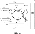
- FIG. 1 is a block diagram illustrating an exemplary resonator fiber optic gyroscope (RFOG) 100 of one embodiment of the present disclosure.
- RFOG 100 comprises a first laser source 110 and second laser source 112 each coupled to a fiber optic resonator 120 by at least one optical coupler 126.
- RFOG 100 further comprises a first servo loop 130, a second servo loop 132, and a dithering processor 135, each of which are discussed in greater detail below.
- first laser source 110 outputs a first optical beam 101 of laser light that is coupled into resonator 120 by coupler 126 and travels around resonator 120 in a first direction.
- the first optical beam 101 is defined as traveling around resonator 120 in a counter-clockwise (CCW) direction.
- Second laser source 112 outputs a second optical beam 102 of laser light that is coupled into resonator 120 by coupler 126 and travels around resonator 120 in a second direction that is opposite to the first direction traveled by optical beam 101.
- the second optical beam 102 is defined as traveling around resonator 120 in a clockwise (CW) direction.
- a single laser source provides a laser that is split using optical components into the first and second optical beams.
- the split first and second optical beams may then be modulated before the first optical beam is coupled into the resonator 120 in the CCW direction and the second optical beam is coupled into the resonator 120 in the CW direction.
- Both optical beams may also be frequency-modulated prior to being introduced into the resonator.
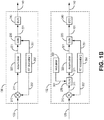
- the modulation of the optical beams is shown in Figure 1b , which illustrates a schematic of devices for determining the center of the resonance ("resonance frequency") of the resonator in each direction.
- RT modulation This modulation will be referred to herein as the resonance tracking modulation (RT modulation) which is applied to the optical beams via RT Modulator 1 to the CCW laser and RT Modulator 2, through summing amplifiers 230 and 330 which drive direct digital synthesizers (DDS) 240 and 340, as shown in Figure 1b .
- DDS 240 and DDS 340 are used to apply reference frequencies that tune laser source 110 and 112 respectively.
- Laser sources 110 and 112 may each be controlled by respective servo loops 1 and 2 (shown at 130 and 132, and in further detail in Figure 1b ) where the laser source 110 introduces light into the resonator 120 in the CCW direction at a CCW input frequency and the laser source 112 introduces light into the resonator 120 in the CW direction at a CW input frequency.
- the lasers may be controlled by the servo loops 1 and 2 such that the lasers may be kept substantially at the resonant frequency for the resonator 120.
- the location of the resonance centers in the CCW and CW directions of the resonator are identified by the servos by applying resonance tracking frequency modulations in RT modulator 1 250 and RT modulator 2 350, respectively, and demodulating the photodetector signals 123 and 125 respectively in mixers 210 and 310 respectively to determine if the first optical beam 101 and the second optical beam 102 are on resonance.
- the time average of the signal content in signals 123 and 125 at the resonance tracking frequencies are zero.
- the servos adjust the center frequency of the first optical beam 101 and the second optical beam 102 so that their time-averaged center frequencies are aligned to the resonances in the two respective directions, and hence the time average of the signal content in signals 123 and 125 at the resonance tracking frequencies will be forced to zero.
- digital accumulators 220 and 320 respectively having zero inputs so they do not accumulate to higher or lower values in their outputs 221 and 321.
- the demodulators 210 and 310 are typically mixers using reference signals from the 252 and 352 respectively from RT modulator 1 250 and RT modulator 2 350 respectively.
- both the CCW input frequency and the CW input frequency would be tuned to the resonance frequencies of the resonator 120 which are approximately equal for low rotation rate.
- the rotation rate output may contain a large error signal at the difference between the input frequencies.
- the large error signal may be in the signal bandwidth where rotation rates of interest are measured.
- the error signal due to backscattered light may be in the band that includes DC up to 100 Hz.
- the backscattered light may lead to the measurement of an incorrect rotation rate.
- the servo loops 1 and 2 may react to the error signal and cause the input frequencies to be locked to one another, which results in a "deadband" where the gyroscope is unable to measure low rotation rates.
- At least one of the input frequencies may be modulated by another modulation (in addition to the resonance tracking modulations) such that the input frequencies are not equal to each other.
- the difference between the input frequencies may be greater than a frequency (i.e. > 100 Hz) that would allow filtering of an error signal that results from the interaction of the light beams having the different input frequencies as the light propagates around the resonator 120 in different directions except for a small amount of time as the frequency of the light beam transitions from one frequency to a second frequency.
- one of the optical beams may be maintained at a resonance frequency of the resonator 120.
- laser source 110 launches a first optical beam 101 into resonator 120 at a specific optical input frequency.
- the first optical beam 101 will exhibit a specific wavelength, (which for laser light can be a wavelength on the order of 1.5 microns, for example).
- optical beam 101 is said to be operating at a resonance frequency, or a resonance center frequency, or at resonance center, of the resonator 120 (which can also be referred to as one of the resonant modes of the resonator 120).
- the optical beam is in phase with its previous pass and the optical power from each pass accumulates to a peak resonant intensity. Any deviation in the input frequency from a resonance frequency will cause optical power within resonator 120 to sum to less than the peak resonant intensity.
- the signal 123 from photodetector 122 will have no signal content at the frequency of the resonance tracking frequency modulation provided by RT Modulator 1 250.
- the frequency of a second optical beam that propagates in the opposite direction of the optical beam propagating at the resonant frequency may be frequency modulated such that it is dithered between different off-resonant frequencies.
- the difference between the frequencies of the two different optical beams may be greater than a filterable frequency throughout most of the operation.
- the filterable frequency may be 100 Hz, thus the difference between the different optical beams may be greater than 100 Hz.
- the average frequency of the off resonant optical beam is on average locked to the resonance frequency for its direction of propagation.
- modulator 360 drives a modulation signal 361 into summing amplifier 370 at a modulation frequency which switches the off resonant laser beam alternatively from one side of the resonance to the other.
- signal 125 will have a frequency component at the resonance tracking modulation frequency that is in phase with resonance tracking modulation reference signal 352 substantially half the time, and that is 180 degrees out of phase with resonance tracking modulation reference signal 352 substantially half the time.
- the time average of demodulator 310 is thus zero, over one complete period of modulation signal 361.
- the magnitude of the difference between the first frequency and the resonance frequency and the difference between the second frequency and the resonance frequency is substantially equal and the frequency of the off-resonance optical beam is above and below the resonance frequency for substantially the same amount of time.
- the magnitude of the difference between the first frequency and the resonance frequency and the difference between the second frequency and the resonance frequency may be different.
- the time that the off-resonant optical beam is at the first frequency and at the second frequency will likewise be not equal such that the off-resonant optical beam is "on-average" at the resonant frequency, and the time average of the output of demodulator 310 will be zero over an integer number of cycles of the modulation signal 361.
- laser source 110 launches optical beam 101 into resonator 120 at a specific optical frequency that is at the resonance frequency.
- laser source 112 launches optical beam 102 into resonator 120 at an off-resonance frequency that is greater than the resonance frequency.
- the laser source 112 may then be controlled such that the off-resonance frequency switches to the second frequency that is lower than the resonance frequency.
- both the frequency of the first laser source 110 and the second laser source 112 are switched between states that are off the resonance frequency.
- both of servo loops 130 and 132 in Figure 1 may be similar to servo loop 132 as represented in Figure 1B .
- the modulator 360 may provide signals to both of servo loops 130 and 132 except the modulation signal from modulator 360 may be inverted before modulation within servo loop 130, such that the modulation of the light beam in servo loop 130 is 180° out of phase with the modulation of the light beam in servo loop 132.
- the first laser source 110 and the second laser source 112 When the first laser source 110 and the second laser source 112 are both off the resonance frequency, the first laser source 110 will be above the resonance frequency when the second laser source 112 is below the resonance frequency. Further, the frequency of the first laser source 110 will switch to a frequency below the resonance frequency at the same time the frequency of the second laser source 112 switches to a frequency that is above the resonance frequency. However, while both the first laser source 110 and the second laser source 112 are not at the resonance frequency except for a brief moment when switching frequencies, they are on-average at the resonance frequency. Further, the difference between the off-resonant frequencies of the first laser source 110 and the second laser source 112 is greater than a frequency level that permits filtering of signals that are produced by the interaction of the first laser 101 and the second laser 102.
- the first laser source 110 and the second laser source 112 may be controlled by respective servo loops (130 and 132) such that the first optical beam 101 and the second beam 102 may be locked to the different frequencies with respect to each other.
- one of the first optical beam 101 and the second optical beam 102 may be locked to the resonance frequency.
- the first optical beam 101 may be locked to a resonance frequency.
- Adjacent longitudinal resonant frequencies are separated from each other based on a function of the free spectral range (FSR) of resonator 120.
- FSR free spectral range
- a dithering processor 135 may control the frequency modulation provided by the servo 1 and servo 2.
- the frequency of optical beam 101 is locked to a resonance frequency by the first resonance switching servo loop 130 while the frequency of optical beam 102 is switched between off-resonance frequencies by the second resonance switching servo loop 132 such that the average frequency of optical beam 102 is on resonance. In one embodiment, this is accomplished by operating servo loops 130 and 132 as frequency locked loops. More specifically, the CCW optical beam is frequency or phase modulated to interrogate the resonator. A portion of the CCW propagating optical beam 101 may be coupled out of the resonator 120 by an optical coupler 127 and delivered to a first photodetector 122, which measures the optical intensity of optical beam 101.
- photodetector 122 produces a resonance tracking signal 123, which is an electrical signal that varies as a function of the measured optical intensity.
- a resonance tracking signal 123 is an electrical signal that varies as a function of the measured optical intensity.
- the photodetector output signal component at the resonance tracking modulation frequency will be proportional to average optical frequency deviations from the resonance frequency. Deviation from the average resonance frequency produces a tracking error at the resonance tracking modulation frequency reflected in resonance tracking signal 123.
- First resonance switching servo loop 130 inputs the resonance tracking signal 123 at the resonance tracking modulation frequency and outputs a control signal 140 to laser source 110 that adjusts the frequency of optical beam 101 to drive the time averaged output of the demodulator over the modulation frequency period (i.e., control signal 140 drives optical beam 101 to the desired average resonance frequency). Further, in some implementations, the control signal 140 drives the frequency of the optical beam 101 to alternate between a first frequency above and a second frequency below the resonance frequency. In the same way, a portion of the CW propagating optical beam 102 is coupled out of resonator 120 by optical coupler 127 and delivered to a second photodetector 124, which measures the optical intensity of optical beam 102.
- photodetector 124 produces a resonance tracking signal 125, which is an electrical signal that varies as a function of the measured optical intensity.
- a resonance tracking signal 125 is an electrical signal that varies as a function of the measured optical intensity.
- the photodetector output signal component at the resonance tracking modulation frequency will be proportional to the average optical frequency deviations from the resonance frequency. Deviation from the average resonance frequency produces a tracking error at the resonance tracking modulation frequency reflected in resonance tracking signal 125.
- the second resonance switching servo loop 132 inputs the resonance tracking signal 125 and outputs a control signal 142 to laser source 112 that adjusts the frequency of optical beam 102 to drive the tracking error at the resonance tracking modulation frequency to zero (i.e., control signal 142 drives optical beam 102 to the desired average resonance frequency). Further, in some implementations, the control signal 142 drives the frequency of the optical beam 102 to alternate between different frequencies above and below the resonance frequency, while driving the optical beam 102 to be at the average resonance frequency. In this case the tracking error at the resonance tracking modulation frequency will average to zero after the beam frequency alternates between being above and below resonance. As noted above, at least one (or both) of the optical beams propagates at a frequency that is off resonance on an instantaneous basis, but is on-resonance on average.
- Figure 2 illustrates a graph 200, showing the frequencies for optical beams 101 and 102, where only one of optical beams 101 and 102 is maintained at the resonance frequency as the optical beams propagate through the resonator 120 for the case of zero rotation rate or negligible rotation rate.
- the first optical beam is modulated by a resonance tracking modulation (not shown) about a resonance frequency 204.
- the frequency 204, about which the first optical beam is modulated remains relatively constant because the first optical beam may be locked to the resonance frequency of the resonator 120.
- the second optical beam frequency 202 of a second optical beam may be dithered such that the resonance tracking modulation modulates the second optical beam about a first frequency that is greater than the resonance frequency for the resonator 120 and a second frequency that is less than the resonance frequency for the resonator 120.
- the difference between the frequency 202 and the resonance frequency, or the first optical beam frequency 204 is sufficiently large enough to enable filtering an error signal that results from backscattered light from the interaction of the first and second optical beams.
- both the first optical beam and the second optical beam may also be modulated by a resonance tracking modulation that modulates the first and second optical beam at a faster frequency than the first and second frequencies as a means of determining what the resonance frequencies, or resonance frequency centers, are.
- the second optical beam frequency 202 transitions from being above the first optical beam frequency 204 to being below the first optical beam frequency 204, the light in both optical beams will briefly interact with one another such that the backscattered light produces an error signal that may be difficult to filter out, such that errors may be produced when the second optical beam frequency 202 transitions from one frequency to another.
- the effects of the errors that arise during the transition between the first and second frequencies is reduced due to the brevity of the interaction.
- the dithered frequency is a square wave
- the dithering of the second optical beam may introduce transients when transitioning between the upper and lower dithered frequencies.
- the output from the resonator may be gated out during and immediately after the second optical beam frequency 202 transitions from being above the resonance frequency to being below the resonance frequency or transitions from being below the resonance frequency to being above the resonance frequency.
- the output of the resonator may be replaced by average measurements that had previously been acquired.
- the rotation of the resonator may cause the difference between the first optical beam frequency 204, which is locked to the resonance frequency of the resonator to become closer towards either the upper or lower dithered frequency 202 of the second optical beam.
- the magnitude of the dither may be increased when the resonator is experiencing rotation.
- a gyroscope system may prevent the frequency of the CCW signal from being within 100 Hz of the CW signal except when a dithered frequency transitions from one frequency to another.
- the difference between the frequencies of the CCW signal and the CW signal may become less than 100 Hz.
- the gyroscope system may change the dithering frequencies of the dithered optical beam such that the difference between the frequencies is greater than 100 Hz.
- Figure 3 illustrates a graph 300, where the frequencies for both optical beams 101 and 102 are dithered about the resonance frequency of the resonator 120 as the optical beams propagates through the resonator 120 for the case of zero rotation rate or negligible rotation rate.
- the first optical beam frequency 306 of a first optical beam is dithered between a first frequency that is greater than the resonance frequency 304 and a second frequency that is less than the resonance frequency 304 of the resonator 120.
- the first optical beam frequency 306 may be dithered by a square wave at a rate of 100 Hz where the first frequency is 500 Hz above the resonance frequency 304 and the second frequency is 500 Hz below the resonance frequency.
- the second optical beam frequency 302 of a second optical beam may be dithered between a first frequency that is greater than the resonance frequency 304 and a second frequency that is less than the resonance frequency 304 but 180° out of phase with the first optical beam frequency 306.
- the second optical beam frequency 302 may also be dithered by a square wave at a rate of 100 Hz where the first frequency is 500 Hz below the resonance frequency 304 and the second frequency is 500 Hz above the resonance frequency.
- the difference between the frequency 302 and the resonance frequency, or the first optical beam frequency 304 is sufficiently large enough to enable filtering an error signal that results from backscattered light from the interaction of the first and second optical beams.
- both the first optical beam and the second optical beam may also be modulated by a resonance tracking modulation that modulates the first and second optical beam at a faster frequency than the first and second frequencies.
- the light in both optical beams may briefly interact with one another such that the backscattered light produces an error signal that may be difficult to filter out, such that errors may be produced when the second optical beam frequency 302 and the first optical beam frequency transition from one frequency to another.
- the effects of the errors that arise during the transition between the first and second frequencies is reduced due to the brevity of the interaction.
- the dithering of the first and second optical beams may introduce transients when transitioning between the upper and lower dithered frequencies.
- the output from the resonator may be gated out during and immediately after the first and second optical beam frequencies transition from being above the resonance frequency 304 to being below the resonance frequency 304 or transitions from being below the resonance frequency 304 to being above the resonance frequency 304.
- the output of the resonator may be replaced by average measurements based on previously acquired measurements.
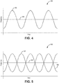
- Figure 4 illustrates a graph 400, showing the frequencies for optical beams 101 and 102, where only one of optical beams 101 and 102 is maintained at the resonance frequency as the optical beams propagates through the resonator 120 for the case of zero rotation rate or negligible rotation rate.
- the first optical beam is modulated by a resonance tracking modulation about a frequency 404.
- the frequency 404, about which the first optical beam is modulated remains relatively constant because the first optical beam may be locked to the resonance frequency of the resonator 120.
- the second optical beam frequency 402 of a second optical beam may be dithered such that the resonance tracking modulation modulates the second optical beam to a first frequency that is greater than the resonance frequency for the resonator 120 and to a second frequency that is less than the resonance frequency for the resonator 120, where the average frequency of the second optical beam is locked to the resonance frequency.
- the second optical beam frequency may be dithered by a sinusoid at a frequency of 100 Hz where the first frequency is 500 Hz above the resonance frequency and the second frequency is 500 Hz below the resonance frequency.
- the difference between the frequency 402 and the resonance frequency, or the first optical beam frequency 404 is sufficiently large enough to enable filtering an error signal that results from backscattered light from the interaction of the first and second optical beams.
- the light in both optical beams may briefly interact with one another such that the backscattered light produces an error signal that may be difficult to filter out, such that errors may be produced when the second optical beam frequency 402 transitions from one frequency to another.
- the dither is sinusoidal, the time when errors are produced due to the interaction of the first and second optical beams may be reduced by either increasing the frequency or amplitude of the dither. Further, as the dither is sinusoidal, the dithering of the second optical beam may not introduce transients as are introduced when the dither is implemented using a square wave.
- the rotation of the resonator may cause the difference between the first optical beam frequency 404, which is locked to the resonance frequency of the resonator to become closer towards either the upper or lower dithered frequency 402 of the second optical beam.
- the magnitude of the dither may be increased when the resonator is experiencing rotation.
- a gyroscope system may prevent the frequency of the CCW signal from being within 100 Hz of the CW signal except when a dithered frequency transitions from one frequency to another.
- the difference between the frequencies of the CCW signal and the CW signal may become less than 100 Hz.
- the gyroscope system may change the dithering frequencies of the dithered optical beam such that the difference between the frequencies is greater than 100 Hz.
- Figure 5 illustrates a graph 500, where the frequencies for both optical beams 101 and 102 are dithered about the resonance frequency of the resonator 120 as the optical beams propagates through the resonator 120, and again, for the case of zero rotation rate or negligible rotation rate.
- the first optical beam frequency 506 of a first optical beam is sinusoidally dithered between a first frequency that is greater than the resonance frequency 504 and a second frequency that is less than the resonance frequency 504 of the resonator 120.
- the first optical beam frequency 506 may be sinusoidally dithered by at a rate of 100 Hz where the first frequency is 500 Hz above the resonance frequency 504 and the second frequency is 500 Hz below the resonance frequency.
- the second optical beam frequency 502 of a second optical beam may be sinusoidally dithered between a first frequency that is greater than the resonance frequency 504 and a second frequency that is less than the resonance frequency 504 but 180° out of phase with the first optical beam frequency 506.
- the first optical beam frequency 506 may also be sinusoidally dithered at a rate of 100 Hz where the first frequency is 500 Hz above the resonance frequency 504 and the second frequency is 500 Hz below the resonance frequency.
- the difference between the frequency 502 and the resonance frequency, or the first optical beam frequency 504 is sufficiently large enough to enable filtering an error signal that results from backscattered light from the interaction of the first and second optical beams.
- the light in both optical beams may briefly interact with one another such that the backscattered light produces an error signal that may be difficult to filter out, such that errors may be produced when the second optical beam frequency 502 and the first optical beam frequency 506 transition from one frequency to another.
- the effects of the errors that arise during the transition between the first and second frequencies is reduced due to the brevity of the interaction.
- the dithering is sinusoidal, the time when errors are produced due to the interaction of the first and second optical beams may be reduced by either increasing the frequency or amplitude of the dither.
- the dithering of the second optical beam may not introduce transients as are introduced when the dither is implemented using a square wave.
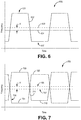
- Figure 6 illustrates a graph 600, showing the frequencies for optical beams 101 and 102, where only one of optical beams 101 and 102 is maintained at its resonance frequency as the optical beams propagate through the resonator 120 when the resonator experiences rotation.
- the resonance frequencies of the resonator in the CW and CCW directions are shifted by a frequency shift ⁇ f due to rotation.
- the first optical beam is modulated by a resonance tracking modulation (not shown) about a frequency 604.
- the frequency 604, about which the first optical beam is modulated remains relatively constant because the first optical beam may be locked to the resonance frequency center of the resonator 120 in its direction.
- the second optical beam traveling in the second direction inside the resonator, of frequency 602, of a second optical beam may be dithered such that the resonance tracking modulation (not shown) modulates the second optical beam about a first frequency 601 that is greater than the resonance center frequency 608 for the resonator 120 and a second frequency 607 that is less than the resonance center frequency for the resonator 120, where the average frequency of the second optical beam is locked to the center frequency of the resonance 608.
- the resonance center frequency in 608 is shifted from the other resonance center frequency 604 by a frequency difference resulting from inertial rotation of the gyro.
- the second optical beam frequency may be dithered by a sinusoid at a frequency of 100 Hz where the first frequency is 500 Hz above the resonance frequency (same as "resonance frequency center") and the second frequency is 500 Hz below the resonance frequency.
- the difference between the frequency 602 and the resonance frequency, or the first optical beam frequency 604 is sufficiently large enough to enable filtering an error signal that results from backscattered light from the interaction of the first and second optical beams.
- Figure 7 illustrates a graph 700, where the frequencies for both optical beams 101 and 102 are dithered about the resonance frequency of the resonator 120 as the optical beams propagates through the resonator 120, when the resonator experiences rotation and the resonance frequencies of the resonator in the CW and CCW directions are shifted by a frequency shift ⁇ f due to rotation.
- the first optical beam frequency 706 of a first optical beam is square-wave dithered between a first frequency 702 that is greater than the resonance frequency 707 and a second frequency 701 that is less than the resonance frequency 707 of the resonator 120.
- the first optical beam frequency 706 may be square-wave dithered at a rate of 100 Hz where the first frequency is 500 Hz above the resonance frequency 707 and the second frequency is 500 Hz below the resonance frequency.
- the second optical beam frequency 711 of a second optical beam may be square-wave dithered between a first frequency 709 that is greater than the resonance frequency 708 and a second frequency 710 that is less than the resonance frequency 708 but 180° out of phase with the square wave dither waveform that is applied to the first optical beam frequency 706.
- the first optical beam frequency 706 may also be square-wave dithered at a rate of 100 Hz where the first frequency is 500 Hz above the resonance frequency 707 and the second frequency is 500 Hz below the resonance frequency.
- the difference between the frequency 711 and the optical beam frequency 706 is sufficiently large enough to enable filtering an error signal that results from backscattered light from the interaction of the first and second optical beams at frequencies 706 and 711, respectively.
- the resonant frequencies 707 and 708 are shifted from each other due to rotation of the gyroscope by an amount ⁇ f, the upper and lower frequencies extremes of the frequency modulation of the first optical beam frequency 706 and second optical beam frequency 711 also change in accordance such that resulting backscattered light may be filtered out of measurements.
- other dithering waveforms may be used such as sinusoidal modulation, to reduce transients in signal processing electronics and servo systems.
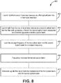
- Figure 8 is a flow diagram illustrating a method 800 for dynamic bias offset operation in resonator fiber optic gyroscope.
- Method 800 begins at 802, where light from one or more laser sources is launched as a first optical beam into a fiber optic resonator.
- a laser source may produce a first optical beam that is coupled into the fiber optic resonator to propagate in the CCW direction.
- Method 800 then proceeds to 804, where light from the one or more laser sources is launched as a second optical beam into the fiber optic gyroscope, where the second optical beam propagates in a direction opposite the first optical beam.
- a second laser source may produce a second optical beam that is coupled into the fiber optic resonator to propagate in the CW direction.
- the first optical beam and the second optical beam are produced by the same laser source, and optics then introduce the different optical beams from the single laser source into the fiber optic resonator to propagate in different directions within the resonator.
- method 800 then proceeds at 806, where the average frequency of the first optical beam and the second optical beam are locked to a resonance frequency.
- the one or more laser source may be coupled to one or more servos. The servos send control signals to the one or more laser sources to control the average frequency of the light produced by the one or more lasers.
- the method 800 then proceeds at 808, where the second optical beam is frequency modulated.
- the second optical beam may be frequency modulated such that the second optical beam is dithered about the resonance frequency.
- Method 800 then proceeds at 810, where signals that result from the interference of the first optical beam with the second optical beam are attenuated.
- the interaction of the first optical beam with the second optical beam may be due to backscattered light.
- This backscattered light may produce a signal at the photodetector at a filterable frequency.
- the filter may then remove the signal produced from the backscattered light. By removing the error due to the backscattered signal, bias errors and low rotation rate errors may be reduced.
Landscapes
- Physics & Mathematics (AREA)
- Engineering & Computer Science (AREA)
- Optics & Photonics (AREA)
- Electromagnetism (AREA)
- Power Engineering (AREA)
- General Physics & Mathematics (AREA)
- Radar, Positioning & Navigation (AREA)
- Remote Sensing (AREA)
- Gyroscopes (AREA)
Applications Claiming Priority (1)
| Application Number | Priority Date | Filing Date | Title |
|---|---|---|---|
| US201715591950 | 2017-05-10 |
Publications (1)
| Publication Number | Publication Date |
|---|---|
| EP3401641A1 true EP3401641A1 (fr) | 2018-11-14 |
Family
ID=61622397
Family Applications (1)
| Application Number | Title | Priority Date | Filing Date |
|---|---|---|---|
| EP18161055.1A Ceased EP3401641A1 (fr) | 2017-05-10 | 2018-03-09 | Systèmes et procédés de fonctionnement de décalage de polarisation dynamique dans un gyroscope à fibres optiques de résonateur |
Country Status (1)
| Country | Link |
|---|---|
| EP (1) | EP3401641A1 (fr) |
Citations (4)
| Publication number | Priority date | Publication date | Assignee | Title |
|---|---|---|---|---|
| US4825261A (en) * | 1986-07-29 | 1989-04-25 | Litef Gmbh | Method for reading out rotation rate with a passive optical resonator |
| EP0507536A2 (fr) * | 1991-04-05 | 1992-10-07 | British Aerospace Public Limited Company | Gyroscope à résonateur annulaire |
| EP2293014A2 (fr) * | 2009-08-12 | 2011-03-09 | Honeywell International Inc. | Gyroscope optique à résonateur doté d'une modulation de faisceau d'entrée optimisée pour une sensibilité élevée et une faible polarisation |
| US20120050745A1 (en) * | 2010-08-30 | 2012-03-01 | Honeywell International Inc. | Resonator fiber optic gyroscopes with reduced rotation rate instability from back reflections |
-
2018
- 2018-03-09 EP EP18161055.1A patent/EP3401641A1/fr not_active Ceased
Patent Citations (4)
| Publication number | Priority date | Publication date | Assignee | Title |
|---|---|---|---|---|
| US4825261A (en) * | 1986-07-29 | 1989-04-25 | Litef Gmbh | Method for reading out rotation rate with a passive optical resonator |
| EP0507536A2 (fr) * | 1991-04-05 | 1992-10-07 | British Aerospace Public Limited Company | Gyroscope à résonateur annulaire |
| EP2293014A2 (fr) * | 2009-08-12 | 2011-03-09 | Honeywell International Inc. | Gyroscope optique à résonateur doté d'une modulation de faisceau d'entrée optimisée pour une sensibilité élevée et une faible polarisation |
| US20120050745A1 (en) * | 2010-08-30 | 2012-03-01 | Honeywell International Inc. | Resonator fiber optic gyroscopes with reduced rotation rate instability from back reflections |
Similar Documents
| Publication | Publication Date | Title |
|---|---|---|
| US9115994B2 (en) | Systems and methods sideband heterodyning detection | |
| EP2857796B1 (fr) | Méthode et système de suivi/asservissement de l'intervalle spectral libre d'un résonateur et applications dans un gyroscope à fibre optique. | |
| EP2770298B1 (fr) | Procédé et système de détection de fréquences de résonance de résonateur annulaire optique et plage spectrale libre afin de réduire le nombre de lasers dans un gyroscope à fibre optique de résonateur | |
| EP2221579B1 (fr) | Correction d'erreurs de modulation dans un RFOG | |
| US9354064B2 (en) | Resonator fiber optic gyroscope employing common cavity length modulation along with high bandwidth laser stabilization | |
| EP2333482A2 (fr) | Réducteur d'erreurs de lumière-phase-bruit | |
| EP3106835B1 (fr) | Systèmes et procédés pour gyroscopes à fibres optiques à résonateur utilisant des résonateurs en anneau de référence | |
| JP2014039027A (ja) | 透過モードおよび反射モードの帰還制御部を備えたレーザ | |
| US8873063B2 (en) | Low noise resonator fiber optic gyro | |
| EP3922945B1 (fr) | Systèmes et procédés pour réduire les harmoniques différentielles de modulation de suivi de résonance dans un gyroscope à fibre optique résonant | |
| US10175047B2 (en) | Systems and methods for dynamic bias offset operation in resonator fiber optic gyroscope | |
| US5325174A (en) | Integrated optic gyro with one Bragg transducer | |
| US7869052B2 (en) | Method and amplifying stage for suppressing modulation distortion rate sensing errors in a resonator fiber optic gyroscope | |
| Takiguchi et al. | Removal of lock-in phenomenon in optical passive ring-resonator gyros by using optical Kerr effect in fiber resonator | |
| EP3401641A1 (fr) | Systèmes et procédés de fonctionnement de décalage de polarisation dynamique dans un gyroscope à fibres optiques de résonateur | |
| Wang et al. | Suppression of backscattering-induced noise in a resonator optic gyro by the dual-frequency modulation method | |
| EP3617648B1 (fr) | Réducteur d'erreur de décalage de modulation hyperbolique pour un rfog | |
| US11624614B1 (en) | Reducing rotation sensing errors from laser source signal and modulation cross-talk | |
| EP3783311A1 (fr) | Commutation d'hétérodyne de bande latérale pour gyroscopes à résonateur à fibre optique (rfogs) | |
| JPH06235641A (ja) | 光ファイバジャイロスコープ | |
| EP0388530B1 (fr) | Gyroscope à fibre optique | |
| JPH04109115A (ja) | 光ジャイロ |
Legal Events
| Date | Code | Title | Description |
|---|---|---|---|
| PUAI | Public reference made under article 153(3) epc to a published international application that has entered the european phase |
Free format text: ORIGINAL CODE: 0009012 |
|
| STAA | Information on the status of an ep patent application or granted ep patent |
Free format text: STATUS: REQUEST FOR EXAMINATION WAS MADE |
|
| 17P | Request for examination filed |
Effective date: 20180309 |
|
| AK | Designated contracting states |
Kind code of ref document: A1 Designated state(s): AL AT BE BG CH CY CZ DE DK EE ES FI FR GB GR HR HU IE IS IT LI LT LU LV MC MK MT NL NO PL PT RO RS SE SI SK SM TR |
|
| AX | Request for extension of the european patent |
Extension state: BA ME |
|
| STAA | Information on the status of an ep patent application or granted ep patent |
Free format text: STATUS: EXAMINATION IS IN PROGRESS |
|
| 17Q | First examination report despatched |
Effective date: 20190108 |
|
| RIN1 | Information on inventor provided before grant (corrected) |
Inventor name: SANDERS, GLEN A. Inventor name: STRANDJORD, LEE K. Inventor name: TARANTA, AUSTIN |
|
| STAA | Information on the status of an ep patent application or granted ep patent |
Free format text: STATUS: THE APPLICATION HAS BEEN REFUSED |
|
| 18R | Application refused |
Effective date: 20200326 |
|
| P01 | Opt-out of the competence of the unified patent court (upc) registered |
Effective date: 20230525 |