EP3401560A1 - Crankshaft and conrod assembly - Google Patents
Crankshaft and conrod assembly Download PDFInfo
- Publication number
- EP3401560A1 EP3401560A1 EP17170209.5A EP17170209A EP3401560A1 EP 3401560 A1 EP3401560 A1 EP 3401560A1 EP 17170209 A EP17170209 A EP 17170209A EP 3401560 A1 EP3401560 A1 EP 3401560A1
- Authority
- EP
- European Patent Office
- Prior art keywords
- oil supply
- crankshaft
- conrod
- oil
- supply opening
- Prior art date
- Legal status (The legal status is an assumption and is not a legal conclusion. Google has not performed a legal analysis and makes no representation as to the accuracy of the status listed.)
- Granted
Links
Images



Classifications
-
- F—MECHANICAL ENGINEERING; LIGHTING; HEATING; WEAPONS; BLASTING
- F02—COMBUSTION ENGINES; HOT-GAS OR COMBUSTION-PRODUCT ENGINE PLANTS
- F02B—INTERNAL-COMBUSTION PISTON ENGINES; COMBUSTION ENGINES IN GENERAL
- F02B75/00—Other engines
- F02B75/04—Engines with variable distances between pistons at top dead-centre positions and cylinder heads
- F02B75/045—Engines with variable distances between pistons at top dead-centre positions and cylinder heads by means of a variable connecting rod length
-
- F—MECHANICAL ENGINEERING; LIGHTING; HEATING; WEAPONS; BLASTING
- F16—ENGINEERING ELEMENTS AND UNITS; GENERAL MEASURES FOR PRODUCING AND MAINTAINING EFFECTIVE FUNCTIONING OF MACHINES OR INSTALLATIONS; THERMAL INSULATION IN GENERAL
- F16C—SHAFTS; FLEXIBLE SHAFTS; ELEMENTS OR CRANKSHAFT MECHANISMS; ROTARY BODIES OTHER THAN GEARING ELEMENTS; BEARINGS
- F16C3/00—Shafts; Axles; Cranks; Eccentrics
- F16C3/04—Crankshafts, eccentric-shafts; Cranks, eccentrics
- F16C3/06—Crankshafts
- F16C3/14—Features relating to lubrication
-
- F—MECHANICAL ENGINEERING; LIGHTING; HEATING; WEAPONS; BLASTING
- F02—COMBUSTION ENGINES; HOT-GAS OR COMBUSTION-PRODUCT ENGINE PLANTS
- F02D—CONTROLLING COMBUSTION ENGINES
- F02D15/00—Varying compression ratio
- F02D15/04—Varying compression ratio by alteration of volume of compression space without changing piston stroke
-
- F—MECHANICAL ENGINEERING; LIGHTING; HEATING; WEAPONS; BLASTING
- F16—ENGINEERING ELEMENTS AND UNITS; GENERAL MEASURES FOR PRODUCING AND MAINTAINING EFFECTIVE FUNCTIONING OF MACHINES OR INSTALLATIONS; THERMAL INSULATION IN GENERAL
- F16C—SHAFTS; FLEXIBLE SHAFTS; ELEMENTS OR CRANKSHAFT MECHANISMS; ROTARY BODIES OTHER THAN GEARING ELEMENTS; BEARINGS
- F16C7/00—Connecting-rods or like links pivoted at both ends; Construction of connecting-rod heads
- F16C7/06—Adjustable connecting-rods
-
- F—MECHANICAL ENGINEERING; LIGHTING; HEATING; WEAPONS; BLASTING
- F16—ENGINEERING ELEMENTS AND UNITS; GENERAL MEASURES FOR PRODUCING AND MAINTAINING EFFECTIVE FUNCTIONING OF MACHINES OR INSTALLATIONS; THERMAL INSULATION IN GENERAL
- F16C—SHAFTS; FLEXIBLE SHAFTS; ELEMENTS OR CRANKSHAFT MECHANISMS; ROTARY BODIES OTHER THAN GEARING ELEMENTS; BEARINGS
- F16C9/00—Bearings for crankshafts or connecting-rods; Attachment of connecting-rods
- F16C9/04—Connecting-rod bearings; Attachments thereof
-
- F—MECHANICAL ENGINEERING; LIGHTING; HEATING; WEAPONS; BLASTING
- F01—MACHINES OR ENGINES IN GENERAL; ENGINE PLANTS IN GENERAL; STEAM ENGINES
- F01M—LUBRICATING OF MACHINES OR ENGINES IN GENERAL; LUBRICATING INTERNAL COMBUSTION ENGINES; CRANKCASE VENTILATING
- F01M1/00—Pressure lubrication
- F01M1/06—Lubricating systems characterised by the provision therein of crankshafts or connecting rods with lubricant passageways, e.g. bores
-
- F—MECHANICAL ENGINEERING; LIGHTING; HEATING; WEAPONS; BLASTING
- F01—MACHINES OR ENGINES IN GENERAL; ENGINE PLANTS IN GENERAL; STEAM ENGINES
- F01M—LUBRICATING OF MACHINES OR ENGINES IN GENERAL; LUBRICATING INTERNAL COMBUSTION ENGINES; CRANKCASE VENTILATING
- F01M1/00—Pressure lubrication
- F01M1/06—Lubricating systems characterised by the provision therein of crankshafts or connecting rods with lubricant passageways, e.g. bores
- F01M2001/062—Crankshaft with passageways
-
- F—MECHANICAL ENGINEERING; LIGHTING; HEATING; WEAPONS; BLASTING
- F01—MACHINES OR ENGINES IN GENERAL; ENGINE PLANTS IN GENERAL; STEAM ENGINES
- F01M—LUBRICATING OF MACHINES OR ENGINES IN GENERAL; LUBRICATING INTERNAL COMBUSTION ENGINES; CRANKCASE VENTILATING
- F01M11/00—Component parts, details or accessories, not provided for in, or of interest apart from, groups F01M1/00 - F01M9/00
- F01M11/02—Arrangements of lubricant conduits
- F01M2011/026—Arrangements of lubricant conduits for lubricating crankshaft bearings
-
- F—MECHANICAL ENGINEERING; LIGHTING; HEATING; WEAPONS; BLASTING
- F01—MACHINES OR ENGINES IN GENERAL; ENGINE PLANTS IN GENERAL; STEAM ENGINES
- F01M—LUBRICATING OF MACHINES OR ENGINES IN GENERAL; LUBRICATING INTERNAL COMBUSTION ENGINES; CRANKCASE VENTILATING
- F01M11/00—Component parts, details or accessories, not provided for in, or of interest apart from, groups F01M1/00 - F01M9/00
- F01M11/02—Arrangements of lubricant conduits
- F01M2011/027—Arrangements of lubricant conduits for lubricating connecting rod bearings
-
- F—MECHANICAL ENGINEERING; LIGHTING; HEATING; WEAPONS; BLASTING
- F16—ENGINEERING ELEMENTS AND UNITS; GENERAL MEASURES FOR PRODUCING AND MAINTAINING EFFECTIVE FUNCTIONING OF MACHINES OR INSTALLATIONS; THERMAL INSULATION IN GENERAL
- F16C—SHAFTS; FLEXIBLE SHAFTS; ELEMENTS OR CRANKSHAFT MECHANISMS; ROTARY BODIES OTHER THAN GEARING ELEMENTS; BEARINGS
- F16C17/00—Sliding-contact bearings for exclusively rotary movement
- F16C17/02—Sliding-contact bearings for exclusively rotary movement for radial load only
-
- F—MECHANICAL ENGINEERING; LIGHTING; HEATING; WEAPONS; BLASTING
- F16—ENGINEERING ELEMENTS AND UNITS; GENERAL MEASURES FOR PRODUCING AND MAINTAINING EFFECTIVE FUNCTIONING OF MACHINES OR INSTALLATIONS; THERMAL INSULATION IN GENERAL
- F16C—SHAFTS; FLEXIBLE SHAFTS; ELEMENTS OR CRANKSHAFT MECHANISMS; ROTARY BODIES OTHER THAN GEARING ELEMENTS; BEARINGS
- F16C2360/00—Engines or pumps
- F16C2360/22—Internal combustion engines
-
- F—MECHANICAL ENGINEERING; LIGHTING; HEATING; WEAPONS; BLASTING
- F16—ENGINEERING ELEMENTS AND UNITS; GENERAL MEASURES FOR PRODUCING AND MAINTAINING EFFECTIVE FUNCTIONING OF MACHINES OR INSTALLATIONS; THERMAL INSULATION IN GENERAL
- F16C—SHAFTS; FLEXIBLE SHAFTS; ELEMENTS OR CRANKSHAFT MECHANISMS; ROTARY BODIES OTHER THAN GEARING ELEMENTS; BEARINGS
- F16C33/00—Parts of bearings; Special methods for making bearings or parts thereof
- F16C33/02—Parts of sliding-contact bearings
- F16C33/04—Brasses; Bushes; Linings
- F16C33/06—Sliding surface mainly made of metal
- F16C33/10—Construction relative to lubrication
- F16C33/1025—Construction relative to lubrication with liquid, e.g. oil, as lubricant
-
- F—MECHANICAL ENGINEERING; LIGHTING; HEATING; WEAPONS; BLASTING
- F16—ENGINEERING ELEMENTS AND UNITS; GENERAL MEASURES FOR PRODUCING AND MAINTAINING EFFECTIVE FUNCTIONING OF MACHINES OR INSTALLATIONS; THERMAL INSULATION IN GENERAL
- F16C—SHAFTS; FLEXIBLE SHAFTS; ELEMENTS OR CRANKSHAFT MECHANISMS; ROTARY BODIES OTHER THAN GEARING ELEMENTS; BEARINGS
- F16C7/00—Connecting-rods or like links pivoted at both ends; Construction of connecting-rod heads
- F16C7/04—Connecting-rods or like links pivoted at both ends; Construction of connecting-rod heads with elastic intermediate part of fluid cushion
Definitions
- the disclosure concerns a crankshaft and conrod assembly, a combustion engine with a variable compression ratio as well as a vehicle provided with a combustion engine with a variable compression ratio.
- connection rod or a conrod for a variable compression ratio engine is for example known from US 2015/075497 .
- the conrod in order to achieve a variable length on the conrod, the conrod is provided with a cylinder mechanism adjusting the conrod length, whereby the cylinder mechanism is controlled with oil pressure.
- the oil pressure is provided from a crank pin bearing.
- the present disclosure concerns vehicle with a combustion engine with variable compression ratio and especially a crankshaft and conrod assembly enabling to transferring an oil pressure in to the conrod.
- the subject of the disclosure is to present a crankshaft and conrod assembly enabling a continuous feed of oil pressure to the conrod for controlling the length of the conrod.
- Another aspect of the disclosure is to present a variable compression ratio combustion engine provided with a crankshaft and conrod assembly and jet another aspect of the disclosure is to present a vehicle provided with the mentioned combustion engine.
- Oil pressure is fed to the conrod through an oil supply opening in the crankpin journal, which opening feeds to an oil groove in a bearing sleeve.
- Having one oil groove extending about the whole circumference of the crankpin bearing allow just one oil supply opening in order to continuously provide the conrod with oil pressure independent of angular position of the conrod upon the crankpin journal.
- one oil groove extending about the whole circumference would also collapse the oil film and drive the need for a wider bearing, which is in most cases undesired.
- crankshaft and conrod assembly comprising a crankshaft and a conrod, alternative and equivalent wording for a conrod is a connection rod.
- the crankshaft comprises a rotational axis and one crankpin journal arranged offset to the rotational axis of the crankshaft.
- the crankshaft conrod assembly at least one conrod is provided upon the crankpin journal.
- the crankshaft is provided with an oil supply structure for supplying the crankpin journal with lubrication oil and the conrod with an oil pressure. This allows a continuous lubrication of the crankpin journal. Additionally the oil supply structure transfers a continuous pressurized oil in to an oil channel structure in the conrod.
- the oil supply structure comprises an oil supply conduit provided between a main journal, which is coaxial with the rotational axis of the crankshaft and the crankpin journal first and a second oil supply opening at the crankpin journal, and a connection point where the oil supply conduit connects to the first and second oil supply opening.
- the oil supply openings are provided as conduits extending between the surface of the crankpin journal and the oil supply conduit.
- the oil supply openings can for example be provided as drill holes or be pre-formed in the goods during casting of the crankshaft.
- a crankpin bearing comprises of a crankpin journal and a conrod bearing sleeve, when the bearing sleeve is mounted upon the crankpin journal.
- the conrod is arranged upon the crank pin journal through its bearing sleeve, at which at least a first and a second oil groove are provided in a circumferential direction at an inner surface of the bearing sleeve.
- the first oil supply opening is provided at a first radial distance from a rotational axis of the crankshaft.
- the second oil supply opening is provided at a second radial distance from the rotational axis of the crankshaft.
- the connection point is provided at a third radial distance from the rotational axis of the rotational axis of the crankshaft. Both the first and second radial distances are larger or equal to the third radial distance.
- An exemplary effect of the arrangement of the oil supply openings according to this is that all oil supply openings are provided at, a minimum, the same distance from the rotational axis of the crankshaft whereby a centrifugal force never will have a negative effect on the oil pressure in between the connection point and the oil supply openings. In all positions where the oil supply openings are provided at a distance larger than the distance between the connection point and the rotational axis of the crankshaft, the centrifugal force will even increase the oil pressure in the position between the connection point and the oil
- Additional oil supply openings could be provided in between the first and second oil supply openings. All additional oil supply openings beyond the first and second oil supply openings may be provided in between the first and second oil supply opening such that the additional oil supply openings are provided at distance from the rotational axis of the crankshaft larger than the distance between the connection point and the rotational axis of the crankshaft.
- an opening angle (A) between the first and the second oil supply opening is larger or equal to the angels (B1, B2) between the opposing end portions of the two oil grooves and the angular length (C1, C2) of the respective oil groove is larger or equal to the angels (B1, B2) between the opposing end portions of the two oil grooves.
- An exemplary effects, of the relation between the opening angle between the first and second oil supply opening, the angle between the opposing end portions of the oil grooves and the angular length of the oil grooves, is that at least one oil groove will always be in fluid contact with one oil supply opening, whereby oil pressure always will be provided to the conrod, independent of angular position upon the crankpin journal and at the same time enabling that the oil grooves can be held as short as possible and thereby maximising the bearing surface and minimising the needed width of the bearing.
- crankshaft and conrod assembly An another exemplary embodiment of the crankshaft and conrod assembly the angle (A) between the first and the second oil supply opening is larger than an angle (B1, B2) between opposing end portions of the two oil grooves and the angle (A) between the first and the second oil supply opening is larger than the angular distance (C1, C2) of at least one of the oil grooves and at least a third oil supply opening is provided in between the first and the second oil supply opening.
- An exemplary effect of the above exemplary embodiment is that the oil grooves in the bearing sleeve can be made shorter and thereby the load bearing surface in the bearing larger, whereby the third oil supply opening still ensures that at least one oil groove is in fluid contact with one oil supply opening, whereby oil pressure always will be provided to the conrod independent of angular position upon the crankpin journal. This maximises the bearing surface and minimising the needed width of the bearing for take up the loads the bearing is subjected to.
- the first and second oil supply opening can be connected with a channel extending as a chord between the first and second oil supply opening.
- the connection point is thereby provided at the proximity of the one of the first and second oil supply openings that is arranged the shortest distance from the rotational axis of the crankshaft. Additional oil supply openings arranged in-between the first and second oil supply opening can connect directly to the chord.
- chord connection An exemplary effect of a chord connection is that a minimal of post machining is needed in order to create the oil supply openings. I.e two oil supply openings can be achieved with just one drill hole.
- an oil supply channel to the connection point is provided close to the one of the first and second oil supply opening that is at the shortest radial distance from the rotational axis of the crankshaft.
- the oil supply openings are also located such that all positions along the chord are at a larger radial distance from the rotational axis of the crankshaft than the oil supply opening closest to the rotational axis of the crankshaft. Exemplary effects thereof is that the an easy manufacturing of the oil supply channel will be possible through drilling and that the centrifugal force will not have any negative effect on the oil pressure between the connection point and the two oil supply openings.
- a third oil supply opening is provided in-between the first and second oil supply opening.
- the third oil supply opening connects directly to the chord through e.g. a drill hole.
- connection point can be provided at a centre axis of the crankpin journal, whereby the oil channels to the oil supply openings extends essentially perpendicular from an outer surface of the crankpin journal to the connection point.
- the oil supply may constitute of drill holes, but may also be pre-formed in the material or manufactured in any other suitable manner.
- Exemplary opening angles between the first and the second oil supply opening is between 85 and 180 degrees.
- the opening angle between the first and the second oil supply opening is e.g. in-between 85 and 95 degrees.
- the first and the second oil groove can exemplary be provided with at least one feeding hole respectively, through which the conrod is fed with oil pressure.
- the feeding holes typically extend through the bearing sleeve, enabling the oil pressure to reach the oil pressure conduits of the conrod.
- a crankshaft can be provided with a plurality of crankpin journals, where, for the application, a suitable number of crankpin journals are provided with a conrod. This could be anything from all to one of the crankpin journals that is provided with a conrod.
- a variable compression ratio combustion engine is provided with a crankshaft and conrod assembly.
- the combustion engine can have any odd or even number of cylinders.
- crankshaft and conrod assembly is arranged in the combustion engine such that when the combustion in the cylinder of the combustion engine exercises its highest force upon the conrod, the bearing sleeve and the oil supply openings are arranged such that a centre axis of the conrod is located above a surface of the crankpin journal where no oil supply opening is located.
- a vehicle is provided with the variable compression ratio combustion engine with the crankshaft and conrod assembly.
- crankshaft and conrod assembly have been described in conjunction with a combustion engine and a vehicle, however the crankshaft and conrod assembly is suitable to use in any other application where the conrod needs to be fed with an oil pressure.
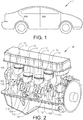
- Fig. 1 and 2 is provided to get an overview of an exemplary environment of the crankshaft and conrod assembly 100 of the present disclosure.
- Fig. 1 shows a schematic drawing of a vehicle 1 that can be provided with a combustion engine 10 and crankshaft and conrod assembly 100 as presented in this disclosure.
- Fig. 2 discloses an exemplary variable compression ratio combustion engine 10 provided with a crankshaft and conrod assembly 100 as presented in this disclosure.
- the exemplary combustion engine 10 in figure 2 is a four cylinder engine, whereby the exemplary crankshaft 110 is provided with four crankpin journals 112.
- Upon each crankpin journal 112 is a conrod 150 mounted, which connects to the pistons 11 to reciprocate in the cylinders 12.
- the principle of the disclosed crankshaft and conrod assembly is however applicable in a combustion engine 10 with any number of odd or even cylinders 12.
- the general idea of the presented crankshaft conrod assembly 100 can be applied upon a crankshaft 110 with at least one crankpin journal 112 or a crankshaft 110 with a plurality of crankpin journals 112.
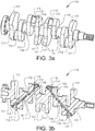
- crankshaft 110 in a perspective ( Fig. 3a ) and a cross section ( Fig. 3b ) is disclosed.
- the crankshaft 110 is provided with five main journals 111, and four crankpin journals 112.
- oil supply conduits 113 is provided within the crankshaft 100 to feed oil out to the crankpin journals 112.
- the oil supply conduits extend from a main journal 111 and extend out to the crankpin journals 112.
- a first and second oil supply opening 114, 115 are provided at the crankpin journals 112 and are connecting with the oil supply conduits 113 in a connection point 116.
- the main journals 111 from which centre the oil supply conduits 113 extend are provided with oil supply openings 118 in order to feed oil pressure into the oil supply conduit 113.
- the arrows indicate the oil feeding direction.
- the oil supply openings 114, 115 are normally disposed in centrally in an axial direction of the crankpin journal 112. Other dispositions could also be used, as long as the oil grooves upon a corresponding bearing sleeve 151 are arranged correspondently.
- This exemplary crankshaft 110 is further provided with counterweights 117.
- the counterweights 117 are provided to balance the crankshaft 110.
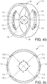
- FIG. 4a an exemplary conrod 150 is disclosed.
- the shaft 160 of the conrod 150 can be varied in length through a not disclosed cylinder mechanism.
- the variable length of the conrod 150 enables a variable compression ratio at a combustion engine 10.
- the cylinder mechanism is controlled through oil pressure, which is fed through the crankpin journal 112, via the bearing sleeve 151 of the conrod 150.
- the upper end of the conrod 150 is provided with a coupling 170 to the piston 11 of the combustion engines 10 cylinder 12.
- crankpin journal 112 In the lower end of the conrod 150 is the connection to crankpin journal 112 provided and it includes the bearing sleeve 151.
- An exemplary embodiment of the bearing sleeve 151 is shown in Fig. 4b and in Fig. 4c in a cross section view.
- the bearing sleeve 151 is the outer part in a sliding bearing, which inner part is the crankpin journal 112, at which the inner surface 156 of the bearing sleeve 151 slides.
- the inner surface 156 of the bearing sleeve 151 is provided with oil grooves 152, 153, which are provided in the circumferential direction on the inner surface 156.
- the axial position of the grooves 152, 153 corresponds to the axial position of the oil feed openings 114, 115 upon the crankpin journals 112. It is important to minimise the area of the oil grooves 152 in order to keep the bearing as small as possible.
- the oil grooves 152, 153 are centrally arranged in the axial direction.
- the oil grooves 152, 153 are provided for feeding oil pressure to the conrod 150 and since the conrod 150 must be provided with a constant oil pressure, at least one of the oil grooves 152, 153 must be in contact with an oil supply opening 114, 115 of the crankpin journal 112 at all times.
- a feeding hole 154 is provided in the proximity of each end 152_1, 152_2, 153_1, 153_2 of the oil grooves 152, 153.
- Alternatives with alternative positioning of the feed holes 154 and/or just one feed hole 154 is possible, just as additional feed holes 154 could be provided if deemed to be necessary, without departing from the scope of the claims.
- the angular length C1, C2 of the oil grooves 152, 153 is important in relation to the angle between oil feed openings 114, 115 upon the crankpin journal 112 and the angles B1, B2 between two opposing ends 152_1, 153_1; 152-2, 153_2 of the oil grooves 152, 153 in order to realise a constant oil pressure to the conrod 150. This will be described more in detail in relation to figure 7a-b.
- the oil grooves 152, 153 are of equal length and are symmetrically arranged in axial, radial and circumferential direction, which gives identical angular lengths C1, C2 of the oil grooves 152, 153 and identical angels B1, B2 between the opposing ends 152_1, 153_1; 152-2, 153_2 respectively.
- Embodiments with oil grooves 152, 153 with different lengths and none symmetrically arrangement, giving different angular lengths C1, C2 and different angles B1, B2 is also possible without departing from the scope of the present disclosure.
- a cross section view through a crankpin journal 112 of the crankshaft 110 is disclosed.
- the cross section is through the first crankpin 112 of the exemplary crankshaft 110 in Fig. 3 , disclosing the connection point 116 of the oil supply conduit 113 and oil supply openings 114, 115.
- Additional crankpins 112 of a crankshaft 110 are preferably provided with a correspondent oil supply structure.
- the exemplary crankpin journal 112 disclosed in Fig. 5a is provided with two oil supply openings 114, 115, which are arranged in an angle A, about 90° towards each other.
- the oil supply openings 114, 115 are realised through channels 114_d, 115_d arranged in an essentially 90° angle from the surface of the crankpin journal 112.
- the oil channels 114d, 115d of the respective oil supply opening 114, 115 meets the oil supply conduit 113 in the connection point 116, which thereby is located in the centre of the crankpins journals 112 rotational axis rx2.
- the two oil supply openings 114, 115 are also arranged in an angle A about 90° towards each other.
- the openings are however connected through one straight oil channel 116d arranged as a chord between the two oil supply openings 114, 115.
- Providing the oil channel 116d as a chord instead of two perpendicular channels means that the oil channel 116d does not extend through the rotational axis rx2 of the crankpin journal 112, whereby the connection point 116 with the oil supply conduit must be provided else were.
- the connection point 116 is provided close to the first oil supply opening 114.
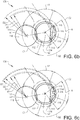
- Fig. 6a a schematic view of a crankshaft conrod assembly 100 provided in an environment of a combustion engine 10.
- the combustion engine 10 is symbolised by the cylinder 12, with the piston 11 in the position where the combustion in the cylinder 12 exercises the highest load Pmax on the piston 11 and therefore also the conrod 150.
- the figure is schematically disclosed and does not reflect the actual measurements of e.g. angles.
- crankshaft conrod assembly common for all the embodiments of the crankshaft conrod assembly is that the first oil supply opening 114 is provided at a first radial distance D1 from a rotational axis rx1 of the crankshaft 110 and that the second oil supply opening 115 is provided at a second radial distance D2 from the rotational axis rx1 and both the first and second radial distance D1, D2 are larger or equal to the distance d1 between the connection point 116 and the rotational axis rx1 of the crankshaft 110.
- Additional oil supply openings 216 (e.g. fig.
- crankshaft conrod assembly 100 will benefit the exemplary effect that the oil pressure fed to the conrod 150 will be helped by or at least not contracted by the centrifugal force caused by the rotation of the crankshaft 110.
- up to three oil supply openings 114, 115, 216 are described, however additional oil supply openings could be provided within the requirements set, without departing from the scope of this disclosure.
- crankshaft and conrod assembly 100 is provided with an opening angle A between the first and the second oil supply opening 114, 115.
- the angle A is larger or equal to the angels B1, B2 between the opposing end portions 152_1, 153_1; 152_2, 153_2 of the two oil grooves 152, 153, and smaller or equal to the angular length C1, C2 of the respective oil groove 152, 153.
- a ⁇ B 1 and B 2 A ⁇ C 1 and C 2 ; C 1 and c 2 ⁇ B 1 and B 2
- An exemplary effect, of the relation between the opening angle A between the first and second oil supply opening, the angle B1, B2 between the opposing end portions 152_1, 153_1; 152_2, 153_2 of the oil grooves 152, 153 and the angular length C1, C2 of the oil grooves 152, 153, is that at least one oil groove 152, 153 will always be in fluid contact with one oil supply opening 114, 115, whereby oil pressure always will be provided to the conrod 150, independent of angular position of the conrod 150 upon the crankpin journal 112 and at the same time enabling that the oil grooves 152, 153 can be held as short as possible and thereby maximising the bearing surface unaffected by oil supply openings/groves that reduce the load carrying capacity of the bearing and thereby minimising the needed width of the bearing.
- connection point 116 can be arranged anywhere as long as the equation d1 ⁇ D1, D2, D3 is fulfilled.
- crankshaft and conrod assembly 100 disclosed in Fig. 6b the same relation between the position of oil supply openings 114, 115 and the oil grooves 152, 153 of the bearing sleeve 151 exists.
- the difference is that the oil supply openings 114, 115 are connected through an oil channel 116d provided as a chord through the crankpin journal 112.
- This also means that the connection point 116 is provided along the chord at the position located closest to the rotational axis rx1 of the crankshaft 110.
- exemplary angles would be angle A between the first and second oil supply opening 114, 115 is 95°, angle B1, B2 is 90° and angle C1, C2 be above 90°.
- the two extreme cases of the opening angle are 0 respective 180 degrees.
- the two oil supply openings are placed on the same position, and reality is only one oil supply opening, whereby the oil grooves in the bearing sleeve must extend 360 degrees about circumference in order to establish a constant oil pressure delivery to the conrod independent of the position of the conrod upon the crankpin journal.
- 180 degrees between the oil supply openings one oil groove extending 180 degrees about the circumference of the bearing sleeve would be sufficient. Any angle between 0 and 180 degrees between the first and second oil supply opening 114, 115 is possible.
- FIG. 6c An alternative exemplary embodiment of oil supply opening layout is disclosed in Fig. 6c , where three oil supply openings 114, 115, 216 are provided. A third oil supply opening 216 have been provided in-between the first and the second oil supply opening 114, 115.
- An exemplary effect of providing three (or more) oil supply openings on the crankpin journal 112 is that by having a larger angle A between the first and second oil supply opening 114, 115 the angular length C1, C2 of the oil grooves 152, 153 can be made smaller and still enabling that at least one oil supply opening 114, 115, 216 are connected to one of the oil grooves 152, 153.
- Smaller oil grooves 152, 153 give a larger bearing surface, which improves the load baring capability of the bearing. Still any angle between 0 and 180 degrees between the first and second oil supply opening 114, 115 is possible. Additional oil supply openings 216 can minimise the length of the grooves in the bearing sleeve 151.
- the first, the second and the third supply opening 114, 115, 216 can be provided by individual channel all connecting to the connection point 116.
- the first and second oil supply opening be connected through a chord channel 116d and the third supply opening connect to the chord channel 116d.
- crankshaft conrod assembly 100 there is more than two oil grooves in the bearing sleeve 151 in combination with additional oil supply openings on the crankpin journal can be provided in order to achieve an optimal bearing surface spread for the intended application of the crankshaft conrod assembly 100.
- crankshaft and conrod assembly suggested in the present disclosure comprises at least two oil supply openings 114, 115.
- the assembly 100 is arranged in the combustion engine 10 such that when the combustion in the cylinder 12 of the combustion engine 10 exercises its highest force Pmax upon the conrod 150, the bearing sleeve 151 and the oil supply openings 114, 115, 216 are arranged such that a centre axis 155 of the conrod 150 is located above a surface of the crankpin journal 112 where no oil supply opening 114, 115, 216 is located.
- This relation is desirable in all application of the crankshaft conrod assembly. In application where there are several positions where there are high loads upon the conrod the disposition of the oil supply openings should be adapted accordingly.
Landscapes
- Engineering & Computer Science (AREA)
- General Engineering & Computer Science (AREA)
- Mechanical Engineering (AREA)
- Chemical & Material Sciences (AREA)
- Combustion & Propulsion (AREA)
- Ocean & Marine Engineering (AREA)
- Shafts, Cranks, Connecting Bars, And Related Bearings (AREA)
- Lubrication Of Internal Combustion Engines (AREA)
- Sliding-Contact Bearings (AREA)
Abstract
Description
- The disclosure concerns a crankshaft and conrod assembly, a combustion engine with a variable compression ratio as well as a vehicle provided with a combustion engine with a variable compression ratio.
- A connection rod or a conrod for a variable compression ratio engine is for example known from
US 2015/075497 . In which it can be seen that in order to achieve a variable length on the conrod, the conrod is provided with a cylinder mechanism adjusting the conrod length, whereby the cylinder mechanism is controlled with oil pressure. The oil pressure is provided from a crank pin bearing. The present disclosure concerns vehicle with a combustion engine with variable compression ratio and especially a crankshaft and conrod assembly enabling to transferring an oil pressure in to the conrod. - The subject of the disclosure is to present a crankshaft and conrod assembly enabling a continuous feed of oil pressure to the conrod for controlling the length of the conrod. Another aspect of the disclosure is to present a variable compression ratio combustion engine provided with a crankshaft and conrod assembly and jet another aspect of the disclosure is to present a vehicle provided with the mentioned combustion engine.
- Oil pressure is fed to the conrod through an oil supply opening in the crankpin journal, which opening feeds to an oil groove in a bearing sleeve. Having one oil groove extending about the whole circumference of the crankpin bearing allow just one oil supply opening in order to continuously provide the conrod with oil pressure independent of angular position of the conrod upon the crankpin journal. However, one oil groove extending about the whole circumference would also collapse the oil film and drive the need for a wider bearing, which is in most cases undesired.
- The crankshaft and conrod assembly comprising a crankshaft and a conrod, alternative and equivalent wording for a conrod is a connection rod.
- The crankshaft comprises a rotational axis and one crankpin journal arranged offset to the rotational axis of the crankshaft. In the crankshaft conrod assembly at least one conrod is provided upon the crankpin journal.
- The crankshaft is provided with an oil supply structure for supplying the crankpin journal with lubrication oil and the conrod with an oil pressure. This allows a continuous lubrication of the crankpin journal. Additionally the oil supply structure transfers a continuous pressurized oil in to an oil channel structure in the conrod. The oil supply structure comprises an oil supply conduit provided between a main journal, which is coaxial with the rotational axis of the crankshaft and the crankpin journal first and a second oil supply opening at the crankpin journal, and a connection point where the oil supply conduit connects to the first and second oil supply opening. The oil supply openings are provided as conduits extending between the surface of the crankpin journal and the oil supply conduit.
- In all the exemplary embodiments, the oil supply openings can for example be provided as drill holes or be pre-formed in the goods during casting of the crankshaft.
- With a conduit is meant any kind of passage, channel or path that fulfils the purpose of transfer an oil pressure between for example the two ends of the conduit or an oil supply opening and a connection point. A crankpin bearing comprises of a crankpin journal and a conrod bearing sleeve, when the bearing sleeve is mounted upon the crankpin journal.
- The conrod is arranged upon the crank pin journal through its bearing sleeve, at which at least a first and a second oil groove are provided in a circumferential direction at an inner surface of the bearing sleeve.
- The first oil supply opening is provided at a first radial distance from a rotational axis of the crankshaft. The second oil supply opening is provided at a second radial distance from the rotational axis of the crankshaft. The connection point is provided at a third radial distance from the rotational axis of the rotational axis of the crankshaft. Both the first and second radial distances are larger or equal to the third radial distance. An exemplary effect of the arrangement of the oil supply openings according to this is that all oil supply openings are provided at, a minimum, the same distance from the rotational axis of the crankshaft whereby a centrifugal force never will have a negative effect on the oil pressure in between the connection point and the oil supply openings. In all positions where the oil supply openings are provided at a distance larger than the distance between the connection point and the rotational axis of the crankshaft, the centrifugal force will even increase the oil pressure in the position between the connection point and the oil supply openings.
- Additional oil supply openings could be provided in between the first and second oil supply openings. All additional oil supply openings beyond the first and second oil supply openings may be provided in between the first and second oil supply opening such that the additional oil supply openings are provided at distance from the rotational axis of the crankshaft larger than the distance between the connection point and the rotational axis of the crankshaft.
- In one exemplary embodiment of the crankshaft and conrod assembly an opening angle (A) between the first and the second oil supply opening is larger or equal to the angels (B1, B2) between the opposing end portions of the two oil grooves and the angular length (C1, C2) of the respective oil groove is larger or equal to the angels (B1, B2) between the opposing end portions of the two oil grooves. I.e.: the following must be fulfilled:


- An exemplary effects, of the relation between the opening angle between the first and second oil supply opening, the angle between the opposing end portions of the oil grooves and the angular length of the oil grooves, is that at least one oil groove will always be in fluid contact with one oil supply opening, whereby oil pressure always will be provided to the conrod, independent of angular position upon the crankpin journal and at the same time enabling that the oil grooves can be held as short as possible and thereby maximising the bearing surface and minimising the needed width of the bearing.
- The oil grooves must not be, but could be arranged such that the angles between the opposing end portions of the two oil grooves are essentially equal, i.e. B1 = B2.
- The angular length of the first oil groove, must not be but can be, essentially equal to the angular length of the second oil groove, i.e. C1 = C2.
- An another exemplary embodiment of the crankshaft and conrod assembly the angle (A) between the first and the second oil supply opening is larger than an angle (B1, B2) between opposing end portions of the two oil grooves and the angle (A) between the first and the second oil supply opening is larger than the angular distance (C1, C2) of at least one of the oil grooves and at least a third oil supply opening is provided in between the first and the second oil supply opening.
- An exemplary effect of the above exemplary embodiment is that the oil grooves in the bearing sleeve can be made shorter and thereby the load bearing surface in the bearing larger, whereby the third oil supply opening still ensures that at least one oil groove is in fluid contact with one oil supply opening, whereby oil pressure always will be provided to the conrod independent of angular position upon the crankpin journal. This maximises the bearing surface and minimising the needed width of the bearing for take up the loads the bearing is subjected to.
- The first and second oil supply opening can be connected with a channel extending as a chord between the first and second oil supply opening. The connection point is thereby provided at the proximity of the one of the first and second oil supply openings that is arranged the shortest distance from the rotational axis of the crankshaft. Additional oil supply openings arranged in-between the first and second oil supply opening can connect directly to the chord.
- An exemplary effect of a chord connection is that a minimal of post machining is needed in order to create the oil supply openings. I.e two oil supply openings can be achieved with just one drill hole.
- In an exemplary embodiment with a chord connection between the first and second oil supply opening an oil supply channel to the connection point is provided close to the one of the first and second oil supply opening that is at the shortest radial distance from the rotational axis of the crankshaft. In this exemplary embodiment the oil supply openings are also located such that all positions along the chord are at a larger radial distance from the rotational axis of the crankshaft than the oil supply opening closest to the rotational axis of the crankshaft. Exemplary effects thereof is that the an easy manufacturing of the oil supply channel will be possible through drilling and that the centrifugal force will not have any negative effect on the oil pressure between the connection point and the two oil supply openings.
- In another exemplary embodiment with a chord connection between the first and second oil supply opening a third oil supply opening is provided in-between the first and second oil supply opening. The third oil supply opening connects directly to the chord through e.g. a drill hole. By connecting the third oil supply opening to the chord at the position along the chord having the shortest radial distance to the rotational axis of the crankshaft, the connection can be extended to realise the connection point to the oil supply conduit, without the need for placing the connection point next to one of the first and second oil supply openings. At the same time the exemplary effects of an easy manufacturing of the oil supply channel will be possible through drilling and the centrifugal force will not have any negative effect on the oil pressure between the connection point and the two oil supply openings.
- The connection point can be provided at a centre axis of the crankpin journal, whereby the oil channels to the oil supply openings extends essentially perpendicular from an outer surface of the crankpin journal to the connection point.
- The oil supply may constitute of drill holes, but may also be pre-formed in the material or manufactured in any other suitable manner.
- Exemplary opening angles between the first and the second oil supply opening is between 85 and 180 degrees. When having just two oil supply openings, the opening angle between the first and the second oil supply opening is e.g. in-between 85 and 95 degrees.
- The first and the second oil groove can exemplary be provided with at least one feeding hole respectively, through which the conrod is fed with oil pressure. The feeding holes typically extend through the bearing sleeve, enabling the oil pressure to reach the oil pressure conduits of the conrod.
- A crankshaft can be provided with a plurality of crankpin journals, where, for the application, a suitable number of crankpin journals are provided with a conrod. This could be anything from all to one of the crankpin journals that is provided with a conrod.
- In an exemplary embodiment, a variable compression ratio combustion engine is provided with a crankshaft and conrod assembly. The combustion engine can have any odd or even number of cylinders.
- In another exemplary embodiment, the crankshaft and conrod assembly is arranged in the combustion engine such that when the combustion in the cylinder of the combustion engine exercises its highest force upon the conrod, the bearing sleeve and the oil supply openings are arranged such that a centre axis of the conrod is located above a surface of the crankpin journal where no oil supply opening is located. This gives the exemplary effect that the crankpin bearing is subjected to its largest forces where it has a full bearing surface to take up the force.
- In one exemplary embodiment a vehicle is provided with the variable compression ratio combustion engine with the crankshaft and conrod assembly.
- The crankshaft and conrod assembly have been described in conjunction with a combustion engine and a vehicle, however the crankshaft and conrod assembly is suitable to use in any other application where the conrod needs to be fed with an oil pressure.
- The invention will be described in greater detail in the following, with reference to the attached drawings, in which
-
Fig. 1 Schematic view of a vehicle. -
Fig. 2 Schematic view of a combustion engine provided with a crankshaft and conrod assembly. -
Fig. 3a, b Schematic view of a conrod. -
Fig. 4 a-c Schematic views of a conrod and a bearing sleeve of a conrod. -
Fig. 5a, b Schematic views of exemplary arrangements of oil supply openings at the crankpin journal. -
Fig. 6a ,b Schematic views of exemplary arrangements of an exemplary crankshaft con rod assembly in a combustion engine. - Various aspects of the disclosure will hereinafter be described in conjunction with the appended drawings to illustrate and not to limit the disclosure, wherein like designations denote like elements, and variations of the described aspects are not restricted to the specifically shown embodiments, but are applicable on other variations of the disclosure. All drawings are schematic.
-
Fig. 1 and 2 is provided to get an overview of an exemplary environment of the crankshaft andconrod assembly 100 of the present disclosure. -
Fig. 1 shows a schematic drawing of avehicle 1 that can be provided with acombustion engine 10 and crankshaft andconrod assembly 100 as presented in this disclosure. -
Fig. 2 discloses an exemplary variable compressionratio combustion engine 10 provided with a crankshaft andconrod assembly 100 as presented in this disclosure. Theexemplary combustion engine 10 infigure 2 is a four cylinder engine, whereby theexemplary crankshaft 110 is provided with fourcrankpin journals 112. Upon eachcrankpin journal 112 is aconrod 150 mounted, which connects to thepistons 11 to reciprocate in thecylinders 12. As apparent, the principle of the disclosed crankshaft and conrod assembly is however applicable in acombustion engine 10 with any number of odd or evencylinders 12. The general idea of the presentedcrankshaft conrod assembly 100 can be applied upon acrankshaft 110 with at least onecrankpin journal 112 or acrankshaft 110 with a plurality ofcrankpin journals 112. - In
Fig. 3a and b anexemplary crankshaft 110 in a perspective (Fig. 3a ) and a cross section (Fig. 3b ) is disclosed. Thecrankshaft 110 is provided with fivemain journals 111, and fourcrankpin journals 112. As can be seenoil supply conduits 113 is provided within thecrankshaft 100 to feed oil out to thecrankpin journals 112. The oil supply conduits extend from amain journal 111 and extend out to thecrankpin journals 112. A first and secondoil supply opening crankpin journals 112 and are connecting with theoil supply conduits 113 in aconnection point 116. Themain journals 111 from which centre theoil supply conduits 113 extend are provided withoil supply openings 118 in order to feed oil pressure into theoil supply conduit 113. The arrows indicate the oil feeding direction. Theoil supply openings crankpin journal 112. Other dispositions could also be used, as long as the oil grooves upon acorresponding bearing sleeve 151 are arranged correspondently. - This
exemplary crankshaft 110 is further provided withcounterweights 117. Thecounterweights 117 are provided to balance thecrankshaft 110. - Now in
Fig. 4a anexemplary conrod 150 is disclosed. Theshaft 160 of theconrod 150 can be varied in length through a not disclosed cylinder mechanism. The variable length of theconrod 150 enables a variable compression ratio at acombustion engine 10. The cylinder mechanism is controlled through oil pressure, which is fed through thecrankpin journal 112, via thebearing sleeve 151 of theconrod 150. - As known, the upper end of the
conrod 150 is provided with acoupling 170 to thepiston 11 of thecombustion engines 10cylinder 12. - In the lower end of the
conrod 150 is the connection tocrankpin journal 112 provided and it includes thebearing sleeve 151. An exemplary embodiment of thebearing sleeve 151 is shown inFig. 4b and inFig. 4c in a cross section view. Thebearing sleeve 151 is the outer part in a sliding bearing, which inner part is thecrankpin journal 112, at which theinner surface 156 of thebearing sleeve 151 slides. - The
inner surface 156 of thebearing sleeve 151 is provided withoil grooves inner surface 156. The axial position of thegrooves oil feed openings crankpin journals 112. It is important to minimise the area of theoil grooves 152 in order to keep the bearing as small as possible. In the exemplary embodiment disclosed inFig. 4a ,b, c theoil grooves - The
oil grooves conrod 150 and since theconrod 150 must be provided with a constant oil pressure, at least one of theoil grooves oil supply opening crankpin journal 112 at all times. - In the exemplary embodiments of the
bearing sleeve 151 disclosed, afeeding hole 154 is provided in the proximity of each end 152_1, 152_2, 153_1, 153_2 of theoil grooves feed hole 154 is possible, just as additional feed holes 154 could be provided if deemed to be necessary, without departing from the scope of the claims. - The angular length C1, C2 of the
oil grooves oil feed openings crankpin journal 112 and the angles B1, B2 between two opposing ends 152_1, 153_1; 152-2, 153_2 of theoil grooves conrod 150. This will be described more in detail in relation to figure 7a-b. - In the exemplary embodiment disclosed in
Fig. 4b and c , theoil grooves oil grooves oil grooves - In
Fig. 5a, b a cross section view through acrankpin journal 112 of thecrankshaft 110 is disclosed. The cross section is through thefirst crankpin 112 of theexemplary crankshaft 110 inFig. 3 , disclosing theconnection point 116 of theoil supply conduit 113 andoil supply openings Additional crankpins 112 of acrankshaft 110 are preferably provided with a correspondent oil supply structure. - The
exemplary crankpin journal 112 disclosed inFig. 5a is provided with twooil supply openings oil supply openings crankpin journal 112. Theoil channels oil supply opening oil supply conduit 113 in theconnection point 116, which thereby is located in the centre of thecrankpins journals 112 rotational axis rx2. - Other angles between the
oil supply openings oil supply openings oil grooves bearing sleeve 151, will be discussed in further detail in relation toFig. 6a ,b. The twooil supply openings crankpin journal 112. - In the
exemplary crankpin journal 112 disclosed inFig. 5b the twooil supply openings straight oil channel 116d arranged as a chord between the twooil supply openings oil channel 116d as a chord instead of two perpendicular channels means that theoil channel 116d does not extend through the rotational axis rx2 of thecrankpin journal 112, whereby theconnection point 116 with the oil supply conduit must be provided else were. In this exemplary embodiment theconnection point 116 is provided close to the firstoil supply opening 114. - Now the relation between the first and second
oil supply opening 114 and any eventual additionaloil supply openings 216 and theoil grooves figures 6a-c . - In
Fig. 6a a schematic view of acrankshaft conrod assembly 100 provided in an environment of acombustion engine 10. Thecombustion engine 10 is symbolised by thecylinder 12, with thepiston 11 in the position where the combustion in thecylinder 12 exercises the highest load Pmax on thepiston 11 and therefore also theconrod 150. The figure is schematically disclosed and does not reflect the actual measurements of e.g. angles. - Common for all the embodiments of the crankshaft conrod assembly is that the first
oil supply opening 114 is provided at a first radial distance D1 from a rotational axis rx1 of thecrankshaft 110 and that the secondoil supply opening 115 is provided at a second radial distance D2 from the rotational axis rx1 and both the first and second radial distance D1, D2 are larger or equal to the distance d1 between theconnection point 116 and the rotational axis rx1 of thecrankshaft 110. Additionaloil supply openings 216, (e.g.fig. 6c ) can be provided at distances D3 that also are larger or equal to the distance d1 between theconnection point 116 and the rotational axis rx1 of thecrankshaft 110. As long as this requirement is fulfilled any suitable number of supply openings above two, can be provided. - Hence, D1, D2 and D3 ≥ d1 and when this criteria is fulfilled the
crankshaft conrod assembly 100 will benefit the exemplary effect that the oil pressure fed to theconrod 150 will be helped by or at least not contracted by the centrifugal force caused by the rotation of thecrankshaft 110. By way of example up to threeoil supply openings - Further to the exemplary embodiment disclosed in
fig. 6a , where the crankshaft andconrod assembly 100 is provided with an opening angle A between the first and the secondoil supply opening oil grooves respective oil groove 


- An exemplary effect, of the relation between the opening angle A between the first and second oil supply opening, the angle B1, B2 between the opposing end portions 152_1, 153_1; 152_2, 153_2 of the
oil grooves oil grooves oil groove oil supply opening conrod 150, independent of angular position of theconrod 150 upon thecrankpin journal 112 and at the same time enabling that theoil grooves - In the exemplary embodiment of
Fig. 6a , theoil grooves oil grooves first oil groove 152 is essentially equal to the angular length C2 of thesecond oil groove 153, i.e. C1 = C2. Still further theoil supply openings oil grooves - In the exemplary embodiment disclosed the
connection point 116 can be arranged anywhere as long as the equation d1 ≤ D1, D2, D3 is fulfilled. - In the exemplary embodiment of the crankshaft and
conrod assembly 100 disclosed inFig. 6b the same relation between the position ofoil supply openings oil grooves bearing sleeve 151 exists. The difference is that theoil supply openings oil channel 116d provided as a chord through thecrankpin journal 112. This also means that theconnection point 116 is provided along the chord at the position located closest to the rotational axis rx1 of thecrankshaft 110. - If in the exemplary embodiments disclosed in
Fig. 6a ,b , exemplary angles would be angle A between the first and secondoil supply opening - The two extreme cases of the opening angle are 0 respective 180 degrees. In the case of 0 degrees the two oil supply openings are placed on the same position, and reality is only one oil supply opening, whereby the oil grooves in the bearing sleeve must extend 360 degrees about circumference in order to establish a constant oil pressure delivery to the conrod independent of the position of the conrod upon the crankpin journal. In the case of 180 degrees between the oil supply openings, one oil groove extending 180 degrees about the circumference of the bearing sleeve would be sufficient. Any angle between 0 and 180 degrees between the first and second
oil supply opening - An alternative exemplary embodiment of oil supply opening layout is disclosed in
Fig. 6c , where threeoil supply openings oil supply opening 216 have been provided in-between the first and the secondoil supply opening crankpin journal 112 is that by having a larger angle A between the first and secondoil supply opening oil grooves oil supply opening oil grooves Smaller oil grooves oil supply opening oil supply openings 216 can minimise the length of the grooves in thebearing sleeve 151. - The first, the second and the
third supply opening connection point 116. Alternatively can as disclosed inFig. 6c the first and second oil supply opening be connected through achord channel 116d and the third supply opening connect to thechord channel 116d. - Within this context also more than two oil grooves in the
bearing sleeve 151 in combination with additional oil supply openings on the crankpin journal can be provided in order to achieve an optimal bearing surface spread for the intended application of thecrankshaft conrod assembly 100. - From one perspective as few
oil supply openings crankshaft 110. However, just one oil supply openings would mean that thebearing sleeve 151 must be provided with an oil groove that extends along the whole circumference in order to ensure continuous oil pressure feed to theconrod 150. This would decrease the load bearing abilities of the bearing, since the total bearing surface would decrease and the hydrodynamic oil pressure in the bearing being reduced by the groove. - However already with a
crankshaft conrod assembly 100 with only twooil supply openings crankpin journal 112 significantlyshorter oil grooves oil supply openings - In an application of the crankshaft and
conrod assembly 100, theassembly 100 is arranged in thecombustion engine 10 such that when the combustion in thecylinder 12 of thecombustion engine 10 exercises its highest force Pmax upon theconrod 150, thebearing sleeve 151 and theoil supply openings centre axis 155 of theconrod 150 is located above a surface of thecrankpin journal 112 where nooil supply opening -
- 1 Vehicle
- 10 Combustion engine
- 11 Piston of cylinder
- 12 Cylinder
- 100 Crankshaft and conrod assembly
- 110 Crankshaft
- 111 Main journal
- 112 Crankpin journal
- 113 Oil supply conduit
- 114 First oil supply opening
- 114_d oil channel
- 115 Second oil supply opening
- 115_d Oil channel
- 116 Connection point
- 116_d Oil channel
- 117 counter weight
- 118 oil supply opening
- 150 Con rod
- 151 Bearing sleeve
- 152 First oil groove
- 152_1 First end
- 152_2 Second end
- 153 Second oil groove
- 153_1 First end
- 153_2 Second end
- 153 Inner surface
- 154 Feeding hole
- 155 centre axis of conrod
- 170 coupling
- 216 third oil supply opening
- A opening angle between first and second oil supply opening
- B1 angle between opposing ends of first and second oil groove
- B2 angle between opposing ends of first and second oil groove
- C1 angular length of first oil groove
- C2 angular length of second oil groove
- rx1 rotational axis of crankshaft
- rx2 centre axis of crankpin journal
- D1 distance between rotational axis of crankshaft and first oil supply opening
- D2 distance between rotational axis of crankshaft and second oil supply opening
- d1 distance between rotational axis of crankshaft and connection point
Claims (12)
- A crankshaft and conrod assembly (100) comprising a crankshaft (110) and a conrod (150), wherein
the crankshaft (110) comprises at least one main journal (111) and one crankpin journal (112), and the at least one conrod (150) is provided upon the crankpin journal (112), and
the crankshaft (110) is provided with an oil supply structure for supplying the crankpin journal (112) with lubrication oil and the conrod (150) with an oil pressure, wherein the oil supply structure comprises:an oil supply conduit (113) provided between the main journal (111) and the crankpin journal (112)at least a first and a second oil supply opening (114, 115) are provided at the crankpin journal (112), anda connection point (116) where the oil supply conduit (113) connects to the first and second oil supply opening (114, 115),and the conrod (150) is arranged upon the crank pin journal (112) through a bearing sleeve (151), at which at least a first and a second oil groove (152, 153) are provided in a circumferential direction at an inner surface (153) of the bearing sleeve (151) and,the first oil supply opening (114) is provide at a first radial distance (D1) from a rotational axis (rx1) of the crankshaft (110) and that the second oil supply opening (115) is provided at a second radial distance (D2) from the rotational axis (rx1) and both the first and second radial distance (D1, D2) are larger than the distance (d1) between the connection point (116) and the rotational axis (rx1) of the crankshaft (110). - Crankshaft and conrod assembly (100) according to claim 1, wherein an opening angle (A) between the first and the second oil supply opening (114, 115) is;
larger or equal to an angel (B1, B2) between opposing end portions (152_1, 153_1) of the two oil grooves (152, 153), and
smaller or equal to the angular length (C1, C2) of the respective oil groove (152, 153). - Crankshaft and conrod assembly (100) of claim 2, wherein the angular length (C1) of the first oil groove (152) is essentially equal to the angular length (C2) of the second oil groove (153).
- Crankshaft and conrod assembly (100) of claim 1, wherein an angle (A) between the first and the second oil supply opening (114, 115) is larger than an angle (B1, B2) between opposing end portions (152_1, 153_1) of the two oil grooves (152, 153) and the angle (A) between the first and the second oil supply opening (114, 115) is larger than the angular distance (C) of at least one of the oil grooves (152, 153) and at least a third oil supply opening (216) is provided in between the first and the second oil supply opening (114, 115).
- Crankshaft and conrod assembly (100) according to any of the preceding claims, wherein the first and second oil supply opening (114, 115) are connected with a channel (116_d) extending as a chord between the first and second oil supply opening (114, 115) and that the connection point (116) is provided at the proximity of the one of the first and second oil supply openings (114, 115) that is arranged the shortest distance (D1, D2) from the rotational axis (rx1) of the crankshaft (110).
- Crankshaft and conrod assembly (100) according to any of the preceding claims 1-4, wherein the connection point (113) is provided at a centre axis (rx2) of the crankpin journal () and the oil supply openings () constitutes drill holes (114_d, 115_d), which extends essentially perpendicular from an outer surface of the crankpin journal (112) to the connection point (116).
- Crankshaft and conrod assembly (100) according to any of the preceding claims 2-6, wherein the opening angle (A) is between 0 and 180 degrees.
- Crankshaft and conrod assembly (100) according to any of the preceding claims, wherein the first and the second oil groove (152, 153) are provided with at least one feeding hole (154) respectively, through which the conrod (150) can be fed with oil pressure.
- Crankshaft and conrod assembly (110) according to any of the preceding claims, wherein the crankshaft (110) is provided with a plurality of crankpin journals (112) and at least one crankpin journal (112) is provided with a conrod (150).
- Combustion engine (10) with variable compression ratio provided with a crankshaft and conrod assembly (100) according to any of the claims 1-9.
- Combustion engine (10) according to claim 10, wherein when the combustion in the cylinder (12) of the combustion engine (10) exercises its highest force (Pmax) upon the conrod (110), the bearing sleeve (151) and the oil supply openings (114, 115, 216) are arranged such that a centre axis (155) of the conrod (110) is located above a surface of the crankpin journal (112) where no oil supply opening (114, 115, 216) is located.
the oil supply openings (114, 115, 216) are arranged such on the circumference of the crank pin journal (112) that centre axis (rx1) of the conrod (150) is arranged at least an angle distance from the first and second oil supply opening (114, 115) in the position where the conrod (150) is subjected to its largest axial forces due to the combustion in the combustion engine (10). - Vehicle (1) provided with a combustion engine (10) with variable compression ratio according to claim 10 or 11.
Priority Applications (4)
| Application Number | Priority Date | Filing Date | Title |
|---|---|---|---|
| EP17170209.5A EP3401560B1 (en) | 2017-05-09 | 2017-05-09 | Crankshaft and conrod assembly |
| EP19203813.1A EP3628878B1 (en) | 2017-05-09 | 2017-05-09 | Crankshaft and conrod assembly |
| US16/611,895 US11085369B2 (en) | 2017-05-09 | 2018-05-08 | Crankshaft and conrod assembly |
| PCT/EP2018/061896 WO2018206589A2 (en) | 2017-05-09 | 2018-05-08 | Crankshaft and conrod assembly |
Applications Claiming Priority (1)
| Application Number | Priority Date | Filing Date | Title |
|---|---|---|---|
| EP17170209.5A EP3401560B1 (en) | 2017-05-09 | 2017-05-09 | Crankshaft and conrod assembly |
Related Child Applications (3)
| Application Number | Title | Priority Date | Filing Date |
|---|---|---|---|
| EP19203813.1A Division EP3628878B1 (en) | 2017-05-09 | 2017-05-09 | Crankshaft and conrod assembly |
| EP19203813.1A Previously-Filed-Application EP3628878B1 (en) | 2017-05-09 | 2017-05-09 | Crankshaft and conrod assembly |
| EP19203813.1A Division-Into EP3628878B1 (en) | 2017-05-09 | 2017-05-09 | Crankshaft and conrod assembly |
Publications (2)
| Publication Number | Publication Date |
|---|---|
| EP3401560A1 true EP3401560A1 (en) | 2018-11-14 |
| EP3401560B1 EP3401560B1 (en) | 2020-03-04 |
Family
ID=58699020
Family Applications (2)
| Application Number | Title | Priority Date | Filing Date |
|---|---|---|---|
| EP17170209.5A Active EP3401560B1 (en) | 2017-05-09 | 2017-05-09 | Crankshaft and conrod assembly |
| EP19203813.1A Active EP3628878B1 (en) | 2017-05-09 | 2017-05-09 | Crankshaft and conrod assembly |
Family Applications After (1)
| Application Number | Title | Priority Date | Filing Date |
|---|---|---|---|
| EP19203813.1A Active EP3628878B1 (en) | 2017-05-09 | 2017-05-09 | Crankshaft and conrod assembly |
Country Status (3)
| Country | Link |
|---|---|
| US (1) | US11085369B2 (en) |
| EP (2) | EP3401560B1 (en) |
| WO (1) | WO2018206589A2 (en) |
Cited By (3)
| Publication number | Priority date | Publication date | Assignee | Title |
|---|---|---|---|---|
| US20180030864A1 (en) * | 2015-08-14 | 2018-02-01 | Bayerische Motoren Werke Aktiengesellschaft | Crankshaft Having an Oil Groove |
| CN112049857A (en) * | 2020-09-04 | 2020-12-08 | 宁波市富川机械有限公司 | Transmission connecting rod structure |
| WO2023247817A1 (en) * | 2022-06-22 | 2023-12-28 | Wärtsilä Finland Oy | Bearing shell, bearing, piston engine and use of a bearing shell |
Families Citing this family (1)
| Publication number | Priority date | Publication date | Assignee | Title |
|---|---|---|---|---|
| US12359690B2 (en) | 2023-09-15 | 2025-07-15 | Cummins Inc. | System for lubricating a crankshaft |
Citations (5)
| Publication number | Priority date | Publication date | Assignee | Title |
|---|---|---|---|---|
| US2444108A (en) * | 1944-05-01 | 1948-06-29 | Norman I Book | Internal-combustion engine |
| GB950215A (en) * | 1961-07-07 | 1964-02-19 | Humber Ltd | Improvements in crankshafts |
| US4201176A (en) * | 1977-01-04 | 1980-05-06 | Sulzer Brothers Limited | Radial bearing for an internal combustion engine |
| US4370901A (en) * | 1981-01-05 | 1983-02-01 | John Sawyer | Connecting rod with variable length |
| US20150075497A1 (en) | 2013-07-05 | 2015-03-19 | Hilite Germany Gmbh | Connecting rod for two stage variable compression |
Family Cites Families (1)
| Publication number | Priority date | Publication date | Assignee | Title |
|---|---|---|---|---|
| US5152373A (en) * | 1991-07-19 | 1992-10-06 | Callies Performance Products | Crankshaft lubricating system |
-
2017
- 2017-05-09 EP EP17170209.5A patent/EP3401560B1/en active Active
- 2017-05-09 EP EP19203813.1A patent/EP3628878B1/en active Active
-
2018
- 2018-05-08 US US16/611,895 patent/US11085369B2/en not_active Expired - Fee Related
- 2018-05-08 WO PCT/EP2018/061896 patent/WO2018206589A2/en not_active Ceased
Patent Citations (5)
| Publication number | Priority date | Publication date | Assignee | Title |
|---|---|---|---|---|
| US2444108A (en) * | 1944-05-01 | 1948-06-29 | Norman I Book | Internal-combustion engine |
| GB950215A (en) * | 1961-07-07 | 1964-02-19 | Humber Ltd | Improvements in crankshafts |
| US4201176A (en) * | 1977-01-04 | 1980-05-06 | Sulzer Brothers Limited | Radial bearing for an internal combustion engine |
| US4370901A (en) * | 1981-01-05 | 1983-02-01 | John Sawyer | Connecting rod with variable length |
| US20150075497A1 (en) | 2013-07-05 | 2015-03-19 | Hilite Germany Gmbh | Connecting rod for two stage variable compression |
Cited By (3)
| Publication number | Priority date | Publication date | Assignee | Title |
|---|---|---|---|---|
| US20180030864A1 (en) * | 2015-08-14 | 2018-02-01 | Bayerische Motoren Werke Aktiengesellschaft | Crankshaft Having an Oil Groove |
| CN112049857A (en) * | 2020-09-04 | 2020-12-08 | 宁波市富川机械有限公司 | Transmission connecting rod structure |
| WO2023247817A1 (en) * | 2022-06-22 | 2023-12-28 | Wärtsilä Finland Oy | Bearing shell, bearing, piston engine and use of a bearing shell |
Also Published As
| Publication number | Publication date |
|---|---|
| EP3628878B1 (en) | 2021-03-17 |
| EP3401560B1 (en) | 2020-03-04 |
| EP3628878A1 (en) | 2020-04-01 |
| US11085369B2 (en) | 2021-08-10 |
| US20210079839A1 (en) | 2021-03-18 |
| WO2018206589A2 (en) | 2018-11-15 |
| WO2018206589A3 (en) | 2018-12-20 |
Similar Documents
| Publication | Publication Date | Title |
|---|---|---|
| US11085369B2 (en) | Crankshaft and conrod assembly | |
| CN107701586B (en) | Connecting rod lubricating device | |
| KR20110059779A (en) | How to dispense fluid to / from the adjustable propeller device and such adjustable propeller device | |
| DE102013108956B3 (en) | Aerostatic bearing for a rotor, in particular in a balancing machine | |
| EP2134985B1 (en) | Mass equalizer transmission of an internal combustion engine | |
| GB2586388A (en) | Integrated bearing section and method | |
| CN105324559B (en) | Bearing structure of multi-link piston crank mechanism of internal combustion engine | |
| GB2541112A (en) | Half thrust bearing and bearing device using the same | |
| US7285052B1 (en) | Intermediate shaft assembly | |
| DE102016224507A1 (en) | Lubrication device of an internal combustion engine to reduce oil leakage | |
| EP3728854A1 (en) | Pump device, in particular submersible pump device | |
| EP4414537A1 (en) | Lubrication system for a pin joint of an engine piston, an engine piston, and a method of lubricating a pin joint of an engine piston | |
| DE69936522T2 (en) | RIGID CRANKSHAFT SUPPORT AND ACTUATOR | |
| EP3056751A1 (en) | A rolling bearing and a mechanical system comprising such a rolling bearing | |
| CN108730457A (en) | A kind of built-in single-surface film throttling static-pressure lead screw pair | |
| KR20250029855A (en) | A bearing with a bearing pin for the use in engines and other devices | |
| DE2435342C3 (en) | Double-sided thrust bearing | |
| WO2018058100A1 (en) | Pin-bushing assembly for enhancing a flow of lubrication in a reciprocating mechanical system | |
| GB2121139A (en) | A device for releasably connecting two shafts together | |
| KR102144407B1 (en) | A large turbocharged two-stroke internal combustion engine | |
| US20160061106A1 (en) | Crankshaft for an internal combustion engine | |
| DE112019003772B4 (en) | Warehouse structure | |
| US10663033B2 (en) | Balance shaft having reduced mass and inertia | |
| JP3487164B2 (en) | Crankshaft lubrication device | |
| EP0679229B1 (en) | A crankshaft for a twostroke internal combustion engine and a method for adjusting same |
Legal Events
| Date | Code | Title | Description |
|---|---|---|---|
| PUAI | Public reference made under article 153(3) epc to a published international application that has entered the european phase |
Free format text: ORIGINAL CODE: 0009012 |
|
| STAA | Information on the status of an ep patent application or granted ep patent |
Free format text: STATUS: THE APPLICATION HAS BEEN PUBLISHED |
|
| AK | Designated contracting states |
Kind code of ref document: A1 Designated state(s): AL AT BE BG CH CY CZ DE DK EE ES FI FR GB GR HR HU IE IS IT LI LT LU LV MC MK MT NL NO PL PT RO RS SE SI SK SM TR |
|
| AX | Request for extension of the european patent |
Extension state: BA ME |
|
| STAA | Information on the status of an ep patent application or granted ep patent |
Free format text: STATUS: REQUEST FOR EXAMINATION WAS MADE |
|
| 17P | Request for examination filed |
Effective date: 20190514 |
|
| RBV | Designated contracting states (corrected) |
Designated state(s): AL AT BE BG CH CY CZ DE DK EE ES FI FR GB GR HR HU IE IS IT LI LT LU LV MC MK MT NL NO PL PT RO RS SE SI SK SM TR |
|
| GRAP | Despatch of communication of intention to grant a patent |
Free format text: ORIGINAL CODE: EPIDOSNIGR1 |
|
| STAA | Information on the status of an ep patent application or granted ep patent |
Free format text: STATUS: GRANT OF PATENT IS INTENDED |
|
| RIC1 | Information provided on ipc code assigned before grant |
Ipc: F16C 3/14 20060101AFI20190903BHEP Ipc: F16C 7/06 20060101ALI20190903BHEP Ipc: F16C 17/02 20060101ALN20190903BHEP Ipc: F16C 9/04 20060101ALI20190903BHEP Ipc: F16C 33/10 20060101ALN20190903BHEP Ipc: F16C 7/04 20060101ALN20190903BHEP |
|
| INTG | Intention to grant announced |
Effective date: 20190926 |
|
| GRAS | Grant fee paid |
Free format text: ORIGINAL CODE: EPIDOSNIGR3 |
|
| GRAA | (expected) grant |
Free format text: ORIGINAL CODE: 0009210 |
|
| STAA | Information on the status of an ep patent application or granted ep patent |
Free format text: STATUS: THE PATENT HAS BEEN GRANTED |
|
| AK | Designated contracting states |
Kind code of ref document: B1 Designated state(s): AL AT BE BG CH CY CZ DE DK EE ES FI FR GB GR HR HU IE IS IT LI LT LU LV MC MK MT NL NO PL PT RO RS SE SI SK SM TR |
|
| REG | Reference to a national code |
Ref country code: GB Ref legal event code: FG4D |
|
| REG | Reference to a national code |
Ref country code: CH Ref legal event code: EP |
|
| REG | Reference to a national code |
Ref country code: AT Ref legal event code: REF Ref document number: 1240701 Country of ref document: AT Kind code of ref document: T Effective date: 20200315 |
|
| REG | Reference to a national code |
Ref country code: DE Ref legal event code: R096 Ref document number: 602017012457 Country of ref document: DE |
|
| REG | Reference to a national code |
Ref country code: IE Ref legal event code: FG4D |
|
| PG25 | Lapsed in a contracting state [announced via postgrant information from national office to epo] |
Ref country code: RS Free format text: LAPSE BECAUSE OF FAILURE TO SUBMIT A TRANSLATION OF THE DESCRIPTION OR TO PAY THE FEE WITHIN THE PRESCRIBED TIME-LIMIT Effective date: 20200304 Ref country code: NO Free format text: LAPSE BECAUSE OF FAILURE TO SUBMIT A TRANSLATION OF THE DESCRIPTION OR TO PAY THE FEE WITHIN THE PRESCRIBED TIME-LIMIT Effective date: 20200604 Ref country code: FI Free format text: LAPSE BECAUSE OF FAILURE TO SUBMIT A TRANSLATION OF THE DESCRIPTION OR TO PAY THE FEE WITHIN THE PRESCRIBED TIME-LIMIT Effective date: 20200304 |
|
| REG | Reference to a national code |
Ref country code: NL Ref legal event code: MP Effective date: 20200304 |
|
| PG25 | Lapsed in a contracting state [announced via postgrant information from national office to epo] |
Ref country code: LV Free format text: LAPSE BECAUSE OF FAILURE TO SUBMIT A TRANSLATION OF THE DESCRIPTION OR TO PAY THE FEE WITHIN THE PRESCRIBED TIME-LIMIT Effective date: 20200304 Ref country code: SE Free format text: LAPSE BECAUSE OF FAILURE TO SUBMIT A TRANSLATION OF THE DESCRIPTION OR TO PAY THE FEE WITHIN THE PRESCRIBED TIME-LIMIT Effective date: 20200304 Ref country code: BG Free format text: LAPSE BECAUSE OF FAILURE TO SUBMIT A TRANSLATION OF THE DESCRIPTION OR TO PAY THE FEE WITHIN THE PRESCRIBED TIME-LIMIT Effective date: 20200604 Ref country code: GR Free format text: LAPSE BECAUSE OF FAILURE TO SUBMIT A TRANSLATION OF THE DESCRIPTION OR TO PAY THE FEE WITHIN THE PRESCRIBED TIME-LIMIT Effective date: 20200605 Ref country code: HR Free format text: LAPSE BECAUSE OF FAILURE TO SUBMIT A TRANSLATION OF THE DESCRIPTION OR TO PAY THE FEE WITHIN THE PRESCRIBED TIME-LIMIT Effective date: 20200304 |
|
| REG | Reference to a national code |
Ref country code: LT Ref legal event code: MG4D |
|
| PG25 | Lapsed in a contracting state [announced via postgrant information from national office to epo] |
Ref country code: NL Free format text: LAPSE BECAUSE OF FAILURE TO SUBMIT A TRANSLATION OF THE DESCRIPTION OR TO PAY THE FEE WITHIN THE PRESCRIBED TIME-LIMIT Effective date: 20200304 |
|
| PG25 | Lapsed in a contracting state [announced via postgrant information from national office to epo] |
Ref country code: CZ Free format text: LAPSE BECAUSE OF FAILURE TO SUBMIT A TRANSLATION OF THE DESCRIPTION OR TO PAY THE FEE WITHIN THE PRESCRIBED TIME-LIMIT Effective date: 20200304 Ref country code: RO Free format text: LAPSE BECAUSE OF FAILURE TO SUBMIT A TRANSLATION OF THE DESCRIPTION OR TO PAY THE FEE WITHIN THE PRESCRIBED TIME-LIMIT Effective date: 20200304 Ref country code: IS Free format text: LAPSE BECAUSE OF FAILURE TO SUBMIT A TRANSLATION OF THE DESCRIPTION OR TO PAY THE FEE WITHIN THE PRESCRIBED TIME-LIMIT Effective date: 20200704 Ref country code: SK Free format text: LAPSE BECAUSE OF FAILURE TO SUBMIT A TRANSLATION OF THE DESCRIPTION OR TO PAY THE FEE WITHIN THE PRESCRIBED TIME-LIMIT Effective date: 20200304 Ref country code: PT Free format text: LAPSE BECAUSE OF FAILURE TO SUBMIT A TRANSLATION OF THE DESCRIPTION OR TO PAY THE FEE WITHIN THE PRESCRIBED TIME-LIMIT Effective date: 20200729 Ref country code: EE Free format text: LAPSE BECAUSE OF FAILURE TO SUBMIT A TRANSLATION OF THE DESCRIPTION OR TO PAY THE FEE WITHIN THE PRESCRIBED TIME-LIMIT Effective date: 20200304 Ref country code: SM Free format text: LAPSE BECAUSE OF FAILURE TO SUBMIT A TRANSLATION OF THE DESCRIPTION OR TO PAY THE FEE WITHIN THE PRESCRIBED TIME-LIMIT Effective date: 20200304 Ref country code: LT Free format text: LAPSE BECAUSE OF FAILURE TO SUBMIT A TRANSLATION OF THE DESCRIPTION OR TO PAY THE FEE WITHIN THE PRESCRIBED TIME-LIMIT Effective date: 20200304 Ref country code: ES Free format text: LAPSE BECAUSE OF FAILURE TO SUBMIT A TRANSLATION OF THE DESCRIPTION OR TO PAY THE FEE WITHIN THE PRESCRIBED TIME-LIMIT Effective date: 20200304 |
|
| REG | Reference to a national code |
Ref country code: AT Ref legal event code: MK05 Ref document number: 1240701 Country of ref document: AT Kind code of ref document: T Effective date: 20200304 |
|
| REG | Reference to a national code |
Ref country code: DE Ref legal event code: R097 Ref document number: 602017012457 Country of ref document: DE |
|
| PLBE | No opposition filed within time limit |
Free format text: ORIGINAL CODE: 0009261 |
|
| STAA | Information on the status of an ep patent application or granted ep patent |
Free format text: STATUS: NO OPPOSITION FILED WITHIN TIME LIMIT |
|
| PG25 | Lapsed in a contracting state [announced via postgrant information from national office to epo] |
Ref country code: DK Free format text: LAPSE BECAUSE OF FAILURE TO SUBMIT A TRANSLATION OF THE DESCRIPTION OR TO PAY THE FEE WITHIN THE PRESCRIBED TIME-LIMIT Effective date: 20200304 Ref country code: AT Free format text: LAPSE BECAUSE OF FAILURE TO SUBMIT A TRANSLATION OF THE DESCRIPTION OR TO PAY THE FEE WITHIN THE PRESCRIBED TIME-LIMIT Effective date: 20200304 Ref country code: LI Free format text: LAPSE BECAUSE OF NON-PAYMENT OF DUE FEES Effective date: 20200531 Ref country code: MC Free format text: LAPSE BECAUSE OF FAILURE TO SUBMIT A TRANSLATION OF THE DESCRIPTION OR TO PAY THE FEE WITHIN THE PRESCRIBED TIME-LIMIT Effective date: 20200304 Ref country code: CH Free format text: LAPSE BECAUSE OF NON-PAYMENT OF DUE FEES Effective date: 20200531 |
|
| 26N | No opposition filed |
Effective date: 20201207 |
|
| PG25 | Lapsed in a contracting state [announced via postgrant information from national office to epo] |
Ref country code: SI Free format text: LAPSE BECAUSE OF FAILURE TO SUBMIT A TRANSLATION OF THE DESCRIPTION OR TO PAY THE FEE WITHIN THE PRESCRIBED TIME-LIMIT Effective date: 20200304 Ref country code: PL Free format text: LAPSE BECAUSE OF FAILURE TO SUBMIT A TRANSLATION OF THE DESCRIPTION OR TO PAY THE FEE WITHIN THE PRESCRIBED TIME-LIMIT Effective date: 20200304 |
|
| REG | Reference to a national code |
Ref country code: BE Ref legal event code: MM Effective date: 20200531 |
|
| PG25 | Lapsed in a contracting state [announced via postgrant information from national office to epo] |
Ref country code: LU Free format text: LAPSE BECAUSE OF NON-PAYMENT OF DUE FEES Effective date: 20200509 |
|
| PG25 | Lapsed in a contracting state [announced via postgrant information from national office to epo] |
Ref country code: IE Free format text: LAPSE BECAUSE OF NON-PAYMENT OF DUE FEES Effective date: 20200509 |
|
| PG25 | Lapsed in a contracting state [announced via postgrant information from national office to epo] |
Ref country code: BE Free format text: LAPSE BECAUSE OF NON-PAYMENT OF DUE FEES Effective date: 20200531 |
|
| GBPC | Gb: european patent ceased through non-payment of renewal fee |
Effective date: 20210509 |
|
| PG25 | Lapsed in a contracting state [announced via postgrant information from national office to epo] |
Ref country code: GB Free format text: LAPSE BECAUSE OF NON-PAYMENT OF DUE FEES Effective date: 20210509 |
|
| PG25 | Lapsed in a contracting state [announced via postgrant information from national office to epo] |
Ref country code: TR Free format text: LAPSE BECAUSE OF FAILURE TO SUBMIT A TRANSLATION OF THE DESCRIPTION OR TO PAY THE FEE WITHIN THE PRESCRIBED TIME-LIMIT Effective date: 20200304 Ref country code: MT Free format text: LAPSE BECAUSE OF FAILURE TO SUBMIT A TRANSLATION OF THE DESCRIPTION OR TO PAY THE FEE WITHIN THE PRESCRIBED TIME-LIMIT Effective date: 20200304 Ref country code: CY Free format text: LAPSE BECAUSE OF FAILURE TO SUBMIT A TRANSLATION OF THE DESCRIPTION OR TO PAY THE FEE WITHIN THE PRESCRIBED TIME-LIMIT Effective date: 20200304 |
|
| PG25 | Lapsed in a contracting state [announced via postgrant information from national office to epo] |
Ref country code: MK Free format text: LAPSE BECAUSE OF FAILURE TO SUBMIT A TRANSLATION OF THE DESCRIPTION OR TO PAY THE FEE WITHIN THE PRESCRIBED TIME-LIMIT Effective date: 20200304 Ref country code: AL Free format text: LAPSE BECAUSE OF FAILURE TO SUBMIT A TRANSLATION OF THE DESCRIPTION OR TO PAY THE FEE WITHIN THE PRESCRIBED TIME-LIMIT Effective date: 20200304 |
|
| P01 | Opt-out of the competence of the unified patent court (upc) registered |
Effective date: 20231212 |
|
| PGFP | Annual fee paid to national office [announced via postgrant information from national office to epo] |
Ref country code: DE Payment date: 20250423 Year of fee payment: 9 |
|
| PGFP | Annual fee paid to national office [announced via postgrant information from national office to epo] |
Ref country code: IT Payment date: 20250423 Year of fee payment: 9 |
|
| PGFP | Annual fee paid to national office [announced via postgrant information from national office to epo] |
Ref country code: FR Payment date: 20250423 Year of fee payment: 9 |