EP3401538A1 - Abgasventil für eine verbrennungskraftmaschine - Google Patents
Abgasventil für eine verbrennungskraftmaschine Download PDFInfo
- Publication number
- EP3401538A1 EP3401538A1 EP18171732.3A EP18171732A EP3401538A1 EP 3401538 A1 EP3401538 A1 EP 3401538A1 EP 18171732 A EP18171732 A EP 18171732A EP 3401538 A1 EP3401538 A1 EP 3401538A1
- Authority
- EP
- European Patent Office
- Prior art keywords
- combustion engine
- guide bush
- internal combustion
- valve
- exhaust valve
- Prior art date
- Legal status (The legal status is an assumption and is not a legal conclusion. Google has not performed a legal analysis and makes no representation as to the accuracy of the status listed.)
- Granted
Links
Images
Classifications
-
- F—MECHANICAL ENGINEERING; LIGHTING; HEATING; WEAPONS; BLASTING
- F02—COMBUSTION ENGINES; HOT-GAS OR COMBUSTION-PRODUCT ENGINE PLANTS
- F02M—SUPPLYING COMBUSTION ENGINES IN GENERAL WITH COMBUSTIBLE MIXTURES OR CONSTITUENTS THEREOF
- F02M26/00—Engine-pertinent apparatus for adding exhaust gases to combustion-air, main fuel or fuel-air mixture, e.g. by exhaust gas recirculation [EGR] systems
- F02M26/65—Constructional details of EGR valves
- F02M26/66—Lift valves, e.g. poppet valves
- F02M26/67—Pintles; Spindles; Springs; Bearings; Sealings; Connections to actuators
-
- F—MECHANICAL ENGINEERING; LIGHTING; HEATING; WEAPONS; BLASTING
- F02—COMBUSTION ENGINES; HOT-GAS OR COMBUSTION-PRODUCT ENGINE PLANTS
- F02M—SUPPLYING COMBUSTION ENGINES IN GENERAL WITH COMBUSTIBLE MIXTURES OR CONSTITUENTS THEREOF
- F02M26/00—Engine-pertinent apparatus for adding exhaust gases to combustion-air, main fuel or fuel-air mixture, e.g. by exhaust gas recirculation [EGR] systems
- F02M26/11—Manufacture or assembly of EGR systems; Materials or coatings specially adapted for EGR systems
-
- F—MECHANICAL ENGINEERING; LIGHTING; HEATING; WEAPONS; BLASTING
- F02—COMBUSTION ENGINES; HOT-GAS OR COMBUSTION-PRODUCT ENGINE PLANTS
- F02M—SUPPLYING COMBUSTION ENGINES IN GENERAL WITH COMBUSTIBLE MIXTURES OR CONSTITUENTS THEREOF
- F02M26/00—Engine-pertinent apparatus for adding exhaust gases to combustion-air, main fuel or fuel-air mixture, e.g. by exhaust gas recirculation [EGR] systems
- F02M26/50—Arrangements or methods for preventing or reducing deposits, corrosion or wear caused by impurities
-
- F—MECHANICAL ENGINEERING; LIGHTING; HEATING; WEAPONS; BLASTING
- F02—COMBUSTION ENGINES; HOT-GAS OR COMBUSTION-PRODUCT ENGINE PLANTS
- F02M—SUPPLYING COMBUSTION ENGINES IN GENERAL WITH COMBUSTIBLE MIXTURES OR CONSTITUENTS THEREOF
- F02M26/00—Engine-pertinent apparatus for adding exhaust gases to combustion-air, main fuel or fuel-air mixture, e.g. by exhaust gas recirculation [EGR] systems
- F02M26/65—Constructional details of EGR valves
- F02M26/74—Protection from damage, e.g. shielding means
-
- F—MECHANICAL ENGINEERING; LIGHTING; HEATING; WEAPONS; BLASTING
- F16—ENGINEERING ELEMENTS AND UNITS; GENERAL MEASURES FOR PRODUCING AND MAINTAINING EFFECTIVE FUNCTIONING OF MACHINES OR INSTALLATIONS; THERMAL INSULATION IN GENERAL
- F16J—PISTONS; CYLINDERS; SEALINGS
- F16J15/00—Sealings
- F16J15/16—Sealings between relatively-moving surfaces
- F16J15/18—Sealings between relatively-moving surfaces with stuffing-boxes for elastic or plastic packings
- F16J15/20—Packing materials therefor
- F16J15/22—Packing materials therefor shaped as strands, ropes, threads, ribbons, or the like
-
- F—MECHANICAL ENGINEERING; LIGHTING; HEATING; WEAPONS; BLASTING
- F16—ENGINEERING ELEMENTS AND UNITS; GENERAL MEASURES FOR PRODUCING AND MAINTAINING EFFECTIVE FUNCTIONING OF MACHINES OR INSTALLATIONS; THERMAL INSULATION IN GENERAL
- F16J—PISTONS; CYLINDERS; SEALINGS
- F16J15/00—Sealings
- F16J15/16—Sealings between relatively-moving surfaces
- F16J15/32—Sealings between relatively-moving surfaces with elastic sealings, e.g. O-rings
- F16J15/3284—Sealings between relatively-moving surfaces with elastic sealings, e.g. O-rings characterised by their structure; Selection of materials
- F16J15/3288—Filamentary structures, e.g. brush seals
-
- F—MECHANICAL ENGINEERING; LIGHTING; HEATING; WEAPONS; BLASTING
- F02—COMBUSTION ENGINES; HOT-GAS OR COMBUSTION-PRODUCT ENGINE PLANTS
- F02M—SUPPLYING COMBUSTION ENGINES IN GENERAL WITH COMBUSTIBLE MIXTURES OR CONSTITUENTS THEREOF
- F02M26/00—Engine-pertinent apparatus for adding exhaust gases to combustion-air, main fuel or fuel-air mixture, e.g. by exhaust gas recirculation [EGR] systems
- F02M26/52—Systems for actuating EGR valves
- F02M26/53—Systems for actuating EGR valves using electric actuators, e.g. solenoids
- F02M26/54—Rotary actuators, e.g. step motors
Definitions
- Such exhaust valves are used in particular as exhaust gas recirculation valves for controlling an exhaust gas flow recirculated into the cylinders of the internal combustion engine, which is again supplied in the cylinders for reducing the nitrogen emissions of the combustion.
- the problem is the corrosive gases and the particles contained in the exhaust stream, such as soot particles in the exhaust stream of a diesel engine and the existing thermal load on the valves and their actuators. These sit on the valve stem respectively between the valve rod and the guide bushing and lead to a stiffness of the valve. In addition, hot exhaust gas flows along the valve rod to the actuator and can lead to a thermal overload there.
- the at least one pressed fiber ring abuts axially against the guide bushing. So additional components are avoided and prevents the ingress of contaminants or gases immediately at the position which is to be protected from wear.
- the at least one fiber ring is radially surrounded by a shielding sleeve and the shielding sleeve has a radially inwardly extending portion against which the at least one fiber ring abuts axially.
- the pressing of the fiber ring can be done both axially and radially directly through the shielding sleeve, whereby the assembly is simplified and the fiber ring is protected from further influences from the outside.
- Assembly is particularly simplified when the shielding sleeve is fastened to the guide bush, so that no further components are required for assembly and compression.
- the at least one fiber ring is preferably pressed in between the radially extending section of the shielding sleeve and the axial end of the guide bushing directed towards the valve body.
- a molded sleeve can be easily manufactured by extrusion. The subsequent assembly takes place without additional necessary components for intermediate layer.
- the at least one fiber ring in the pressed state has an outer diameter which corresponds to the outer diameter of the axial section of the guide bush surrounded by the shielding sleeve.
- the shielding sleeve abuts radially against this section of the guide bushing and the at least one compressed fiber ring.
- the shielding sleeve can be made with a cylindrical outer surface and pushed during assembly over a corresponding portion of the guide bush to press the fiber ring.
- a distance between the radially inwardly extending portion of the shielding sleeve and the collar of the shielding sleeve is smaller than the sum of the axial length of the radially surrounded by the shielding portion of the guide bush and the axial height of the at least one fiber ring in the unpressed condition.
- the at least one fiber ring is preferably made of aramid felt mats, stainless steel felt mats, glass fiber felt mats, silicate fiber mats or ceramic felt mats. On the one hand, these materials are insensitive to thermal stress and corrosive environment and on the other hand offer very good sealing properties due to the fibrous material.
- a vent hole can be formed, which serves to establish a pressure equalization between the axially opposite sides of the fiber rings, whereby pressure differences, is pushed through the exhaust gas along the valve stem, for example by occurring Abgaspulsationen.
- a compression in which a sufficient ease of the valve rod can be achieved with good sealing effect is present when the inner diameter is smaller, the outer diameter and the height of each fiber ring in the unpressed state 0.5 to 1.5 mm larger than in the compressed state.
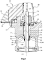
- the figure shows a detail of a side view of an exhaust valve according to the invention in a sectional view.
- the exhaust valve according to the invention has a housing 10, which consists of a flow housing 12 with an inlet 14 and an outlet 16 for the exhaust gas and an actuator housing 18.
- an actuator 20 is formed, which consists of an electric motor 22 and a driven by the electric motor 22 gear 24 is made, via which the movement of the electric motor 22 is transmitted to a valve rod 26 stocky.
- the gear 24 an eccentric, not shown, which cooperates with a gate, not shown, whereby the rotational movement of the electric motor 22 is transmitted in a translational movement of the valve rod 26, which is at least operatively connected to the backdrop.
- the scenery and the eccentric protrude into a gear chamber 28 which is closed by a cap 30, which is attached to the flow housing 12 as well as the actuator housing 18.
- a valve rod 26 radially surrounding return spring 32 is additionally arranged, which is supported on the flow housing 12 and biases the exhaust valve in the closing direction.
- valve rod 26 is mounted in a guide bush 34 which is fixed in a bore 35 of the flow housing 12.
- a valve body 36 is fixed, which cooperates with a valve seat 38 which is formed between the inlet 14 and the outlet 16 in the flow housing 12.
- the valve rod 26 radially surrounding sealant 42 are provided. These consist in the present embodiment of two superposed fiber rings 44, which consist of felt mats, for example, aramid, stainless steel, glass fibers, silicate fibers or ceramics.
- the two fiber rings 44 are inserted into a shielding sleeve 46, which has a cylindrical lateral surface 48, at the first axial end of a radially inwardly extending annular portion 50 and at its opposite axial end an outwardly facing annular collar 52 is formed.
- the lateral surface 48 has an inner diameter, for example, about 1 mm smaller than the outer diameter of the fiber rings 44 in the unpressed state, while the inner diameter of the radially inwardly extending portion 50 is slightly larger than the diameter of the valve rod 26. Accordingly, the fiber rings 44th radially slightly deformed when inserted against the radially extending portion 50 of the shielding sleeve 46 pushed. Subsequently, the shielding sleeve 46 is pushed onto a portion 54 of the guide bushing 34, which faces the valve body 36 and compared to a pointing to the actuator 20 section 55 of the guide bushing 34 has a sales-reduced diameter.
- the length of this section 54 of reduced diameter added to the height of the two stacked Fackedringe 44 in the unassembled state is about 1 to 2 mm greater than the axial length of the lateral surface 48 of the shielding sleeve 46.
- the composite of guide bush 34, shielding sleeve 46 and fiber rings 44 is pushed from the actuator side into the bore 35, which also has a shoulder 58, from which the bore 35 extends with reduced diameter further in the direction of the valve body 36 until the collar 52 is clamped between the shoulder 56 of the guide bush 34 and the shoulder 58 of the bore 35, so that the shielding sleeve 46 can not solve.
- a lip seal 60 is placed in the present embodiment and the valve rod 26 is inserted and connected to the transmission 24.
- the valve rod also has a diameter which is about 1 mm larger than the inner diameter of the fiber rings 44, whereby a good seal of the valve rod 26 is formed, since the fiber rings 44 directly radially pressed against the valve rod 26 abut.
- the exhaust valve according to the invention is correspondingly easy to assemble and has both between the housing and the shielding and between the shielding sleeve and the guide bushing and between the valve rod and the guide bush on a high density, so that penetration of gases or particles in the direction of the actuator reliably prevented.
- this exhaust valve in the area of the gap to be executed as a clearance between the valve rod and the guide bushing, this exhaust valve has an improved seal in comparison to known designs, so that the valve rod and the guide bush are protected against deposits which lead to grooves on the valve rod or the guide bushing , whereby the wear is significantly reduced and so the life is increased.
- an accumulation of particles on the rod or on the inside of the guide bush is avoided, which could otherwise lead to jamming of the valve stem in the guide bushing.
- the scope of the present application is not limited to the embodiment described.
- the housing divisions can be changed or the attachment of the fiber rings can be realized in other ways.
- Also can be dispensed with the lip seal, since already by the fiber rings a usually sufficient tightness is realized.
- a modified assembly in which, for example, the composite of guide bush, shielding and Fiber rings is inserted from the side facing away from the actuator in the housing.
Landscapes
- Engineering & Computer Science (AREA)
- General Engineering & Computer Science (AREA)
- Mechanical Engineering (AREA)
- Chemical & Material Sciences (AREA)
- Combustion & Propulsion (AREA)
- Manufacturing & Machinery (AREA)
- Health & Medical Sciences (AREA)
- Toxicology (AREA)
- Lift Valve (AREA)
Abstract
Description
- Die Erfindung betrifft ein Abgasventil für eine Verbrennungskraftmaschine mit einem Aktor, einer Ventilstange, welche mittels des Aktors bewegbar ist, einem Ventilkörper, der an der Ventilstange befestigt ist, einem Ventilsitz, auf den der Ventilkörper absenkbar ist und von dem der Ventilkörper abhebbar ist, einer Führungsbuchse, welche in einem Gehäuse angeordnet ist und über welches die Ventilstange im Gehäuse gelagert ist und Dichtmitteln zur Abdichtung eines Spaltes zwischen der Führungsbuchse und der Ventilstange.
- Derartige Abgasventile werden insbesondere als Abgasrückführventile zur Regelung eines in die Zylinder des Verbrennungsmotors zurückgeführten Abgasstromes verwendet, der in den Zylindern erneut zur Reduzierung der Stickstoffemissionen der Verbrennung zugeführt wird.
- Diese Ventile werden üblicherweise als Hubventile ausgeführt, bei denen ein an einer Ventilstange befestigter Ventilkörper von einem Ventilsitz zwischen einem Einlass und einem Auslass abhebbar ist oder auf diesen absenkbar ist. Abhängig von der vorhandenen Motorlast wird so der freie Querschnitt zwischen dem Einlass und dem Auslass geregelt, um einen optimalen Abgasstrom zurückzuführen. Für eine möglichst genaue Regelung werden zumeist elektromotorische Aktoren mit nachgeschalteten Getrieben zur Betätigung der Ventilstange verwendet.
- Problematisch sind jedoch die korrosiven Gase sowie die im Abgasstrom enthaltenen Partikel, beispielsweise Rußpartikel im Abgasstrom eines Dieselmotors sowie die vorhandene thermische Belastung der Ventile und deren Aktoren. Diese setzen sich an der Ventilstange beziehungsweise zwischen der Ventilstange und der Führungsbuchse ab und führen zu einer Schwergängigkeit des Ventils. Zusätzlich gelangen heiße Abgasströme entlang der Ventilstange zum Aktor und können dort zu einer thermischen Überlastung führen.
- Daher sind verschiedene Möglichkeiten zur Reduzierung der Ablagerungen und zur Abdichtung der Ventilstange bekannt geworden. So wird in der
DE 10 2010 035 622 A1 ein Abgasrückführventil vorgeschlagen, bei dem an der zum Aktor weisenden Seite der Führungsbuchse ein Radialwellenlippendichtring angeordnet, über den das Eindringen eines Gasstroms oder von Partikeln in den Aktor vermieden werden soll. Dieser weist jedoch eine eingeschränkte thermische Belastbarkeit auf. Zusätzlich weist die Führungsbuchse einen zur Ventilstange gewandten Abschnitt verkleinerten Durchmessers auf, um Ablagerungen von der Ventilstange abzuschaben, bevor diese in den Spalt zwischen Ventilstange und Führungsabschnitt der Buchse gelangen. Aus derDE 10 2015 111 324 A1 ist eine Abschirmhülse bekannt, die zwischen der Führungsbuchse und dem Ventilkörper angeordnet ist, um die Ablagerungen von der Ventilstange zu entfernen. Bei dieser Form der Abschirmhülse besteht jedoch das Problem, dass an der Ventilstange Riefen entstehen können, die die Führungsbuchse beschädigen. Eine Abdichtung kann auf diese Weise nicht zuverlässig realisiert werden. - Des Weiteren ist aus der
DE 103 19 212 B4 über eine Stopfbuchse aus Asbest, die Ventilstange in Richtung des Aktors zwischen dem Aktor und der Führungsbuchse abzudichten. Dies führt jedoch zu deutlich erhöhten Stellkräften und ist lediglich für pneumatisch betätigte Ventile geeignet, welche lediglich eine offene Stellung und eine geschlossene Stellung aufweisen. - Problematisch ist somit, dass keine ausreichende Langlebigkeit der Führungsbuchse gewährleistet werden kann, wodurch eine Leichtgängigkeit der Ventilstange sichergestellt würde, da ein Eindringen von Partikeln in den Spalt zwischen der Ventilstange und der Führungsbuchse nicht ausreichend verhindert wird. Des Weiteren kann ein Eindringen von Gas in Richtung des Aktors nicht ausgeschlossen werden, wodurch die thermische Belastung steigt, so dass häufig zusätzliche Kühlungen des Aktors notwendig werden.
- Es stellt sich daher die Aufgabe, ein Abgasventil für eine Verbrennungskraftmaschine bereit zu stellen, welches über eine lange Lebensdauer sowohl ein Eindringen von Partikeln als auch von Abgasen in Richtung des Aktors deutlich reduziert und gleichzeitig die notwendigen Stellkräfte auch nach vielen Gebrauchsstunden gering hält, indem möglichst Schäden an der Führungsbuchse oder der Ventilstange vermieden werden. Gleichzeitig soll der Verschleiß reduziert werden. Dennoch soll dieses möglichst kostengünstig mit geringem Herstellungs- und Montageaufwand hergestellt werden können.
- Diese Aufgabe wird durch ein Abgasventil für eine Verbrennungskraftmaschine mit den Merkmalen des Hauptanspruchs 1 gelöst.
- Dadurch, dass mindestens ein im verbauten Zustand verpresster Faserring als Dichtmittel die Ventilstange umgibt und axial zwischen dem Ventilkörper und der Führungsbuchse angeordnet ist, wird sowohl ein Eindringen von Gasen und Partikeln in den Spalt zwischen der Führungsbuchse und der Ventilstange verhindert als auch ein Durchdringen dieses Spaltes in Richtung des Aktors, so dass auch die thermische Belastung des Aktors reduziert wird. So wird durch Reduzierung des Verschleißes die Lebensdauer des Abgasventils deutlich erhöht. Dabei bleiben die Herstellkosten sowie der Montageaufwand aufgrund der geringen Teileanzahl gering.
- Vorzugsweise liegt der mindestens eine gepresste Faserring axial gegen die Führungsbuchse an. So werden zusätzliche Bauteile vermieden und das Eindringen der Schmutzstoffe oder Gase unmittelbar an der Position verhindert, welche vor Verschleiß geschützt werden soll.
- Besonders bevorzugt ist es, wenn der mindestens eine Faserring von einer Abschirmhülse radial umgeben ist und die Abschirmhülse einen sich radial nach innen erstreckenden Abschnitt aufweist, gegen den der mindestens eine Faserring axial anliegt. Somit kann direkt durch die Abschirmhülse die Verpressung des Faserringes sowohl axial als auch radial erfolgen, wodurch die Montage vereinfacht und der Faserring vor weiteren Einflüssen von außen geschützt ist.
- Besonders vereinfacht wird die Montage, wenn die Abschirmhülse an der Führungsbuchse befestigt ist, so dass für die Montage und Verpressung keine weiteren Bauteile erforderlich sind.
- Dabei wird vorzugsweise der mindestens eine Faserring zwischen dem sich radial erstreckenden Abschnitt der Abschirmhülse und dem zum Ventilkörper gerichteten axialen Ende der Führungsbuchse eingepresst. Eine derartig geformte Hülse kann einfach durch Strangpressen hergestellt werden. Die anschließende Montage erfolgt ohne zusätzliche notwendige Bauteile zur Zwischenlage.
- Vorteilhafterweise weist der mindestens eine Faserring im verpressten Zustand einen Außendurchmesser auf, der dem Außendurchmesser des von der Abschirmhülse umgebenen axialen Abschnitts der Führungsbuchse entspricht. Zusätzlich liegt die Abschirmhülse radial gegen diesen Abschnitt der Führungsbuchse und den mindestens einen verpressten Faserring an. So kann die Abschirmhülse mit einer zylindrischen Mantelfläche hergestellt werden und bei der Montage über einen entsprechenden Abschnitt der Führungsbuchse geschoben werden, um den Faserring zu verpressen.
- Um auf weitere Befestigungsschritte oder Befestigungsmittel verzichten zu können, ist die Abschirmhülse durch eine Pressverbindung an der Führungsbuchse befestigt.
- In einer vorteilhaften Ausgestaltung der Erfindung weist die Führungsbuchse einen Absatz auf, gegen den die Abschirmhülse mit einem am ersten Ende der Abschirmhülse ausgebildeten Kragen anliegt. Dies dient der einfachen Lagefixierung der Abschirmhülse und somit der Faserringe zur Führungsbuchse, verhindert Montagefehler und legt den Grad der Verpressung der Faserringe fest.
- Um eine solche Verpressung sicher zu stellen, ist ein Abstand zwischen dem sich radial nach innen erstreckenden Abschnitt der Abschirmhülse und dem Kragen der Abschirmhülse kleiner als die Summe der axialen Länge des von der Abschirmhülse radial umgebenen Abschnitts der Führungsbuchse und der axialen Höhe des mindestens einen Faserringes im unverpressten Zustand.
- Eine noch bessere Abdichtung ergibt sich, wenn zumindest zwei Faserringe axial übereinander angeordnet sind.
- Vorzugsweise ist der mindestens eine Faserring aus Aramidfilzmatten, Edelstahlfilzmatten, Glasfaserfilzmatten, Silikatfasermatten oder Keramikfilzmatten. Diese Materialien sind einerseits unempfindlich gegen thermische Belastung und korrosive Umgebung und bieten andererseits durch das faserige Material sehr gute Dichtungseigenschaften.
- Ein zusätzlicher Schutz vor einem Eindringen des Abgases zum Aktor und der daraus folgenden thermischen Belastung wird erreicht, wenn an dem zum verpressten Faserring entgegengesetzten Ende der Führungsbuchse ein Lippendichtring angeordnet ist, der die Ventilstange umgibt.
- Des Weiteren kann vorteilhafterweise in der Führungsbuchse eine Entlüftungsbohrung ausgebildet sein, die dazu dient, einen Druckausgleich zwischen den axial entgegengesetzten Seiten der Faserringe herzustellen, wodurch Druckdifferenzen, durch die Abgas entlang der Ventilstange gedrückt wird, beispielsweise durch auftretende Abgaspulsationen, zu verhindern.
- Eine Verpressung, bei der eine ausreichende Leichtgängigkeit der Ventilstange bei gleichzeitiger guter Abdichtwirkung erzielt werden kann liegt vor, wenn der Innendurchmesser kleiner, der Außendurchmesser und die Höhe jedes Faserringes im unverpressten Zustand 0,5 bis 1,5 mm größer ist als im verpressten Zustand.
- Es wird somit ein Abgasventil mit einer deutlich erhöhten Dichtigkeit über die Lebensdauer geschaffen, welches leicht zu montieren ist und kostengünstig hergestellt werden kann, da die Anzahl der verwendeten Bauteile gering bleibt. So wird bei einem derartigen Ventil der Verschleiß deutlich reduziert, da Ablagerungen und dadurch folgende Beschädigungen, wie Riefen, an der Ventilstange verhindert werden. Auch die thermische Belastung des Aktors wird durch die erhöhte Dichtigkeit verringert.
- Ein Ausführungsbeispiel eines erfindungsgemäßen Abgasventils für einen Verbrennungsmotor ist in der Figur dargestellt und wird nachfolgend beschrieben.
- Die Figur zeigt einen Ausschnitt einer Seitenansicht eines erfindungsgemäßen Abgasventils in geschnittener Darstellung.
- Das erfindungsgemäße Abgasventil weist ein Gehäuse 10 auf, welches aus einem Strömungsgehäuse 12 mit einem Einlass 14 und einem Auslass 16 für das Abgas sowie einem Aktorgehäuse 18 besteht. Im Aktorgehäuse 18 ist ein Aktor 20 ausgebildet, der aus einem Elektromotor 22 sowie einem vom Elektromotor 22 angetriebenen Getriebe 24 besteht, über welches die Bewegung des Elektromotors 22 auf eine Ventilstange 26 untersetzt übertragen wird. Hierzu weist das Getriebe 24 einen nicht dargestellten Exzenter auf, der mit einer nicht dargestellten Kulisse zusammenwirkt, wodurch die rotatorische Bewegung des Elektromotors 22 in eine translatorische Bewegung der Ventilstange 26 übertragen wird, die mit der Kulisse zumindest wirkverbunden ist. Die Kulisse und der Exzenter ragen in einen Getrieberaum 28, der durch eine Abdeckkappe 30 geschlossen wird, welche ebenso wie das Aktorgehäuse 18 am Strömungsgehäuse 12 befestigt ist. Im Getrieberaum 28 ist zusätzlich eine die Ventilstange 26 radial umgebende Rückstellfeder 32 angeordnet, die sich auf dem Strömungsgehäuse 12 abstützt und das Abgasventil in Schließrichtung vorspannt.
- Die Ventilstange 26 ist in einer Führungsbuchse 34 gelagert, welche in einer Bohrung 35 des Strömungsgehäuses 12 befestigt ist. Am zum Aktor 20 entgegengesetzten Ende der Ventilstange 26 ist ein Ventilkörper 36 befestigt, der mit einem Ventilsitz 38 zusammenwirkt, der zwischen dem Einlass 14 und dem Auslass 16 im Strömungsgehäuse 12 ausgebildet ist. Durch Betätigung des Aktors 20 wird so der Ventilkörper 36 über die Ventilstange 26 entgegen der Kraft der Rückstellfeder 32 vom Ventilsitz 38 abgehoben oder durch die Kraft der Rückstellfeder 32 auf diesen abgesenkt und somit der freie Durchströmungsquerschnitt zwischen dem Einlass 14 und dem Auslass 16 geregelt.
- Um einen Spalt 40 zwischen der Ventilstange 26 und der Führungsbuchse 34 abzudichten sind die Ventilstange 26 radial umgebende Dichtmittel 42 vorgesehen. Diese bestehen im vorliegenden Ausführungsbeispiel aus zwei übereinander liegenden Faserringen 44, welche aus Filzmatten beispielsweise aus Aramid, Edelstahl, Glasfasern, Silikatfasern oder Keramiken bestehen. Zur Montage werden die beiden Faserringe 44 in eine Abschirmhülse 46 eingelegt, welche eine zylindrische Mantelfläche 48 aufweist, an deren ersten axialen Ende ein sich radial nach innen erstreckenden ringförmigen Abschnitt 50 und an deren entgegengesetzten axialen Ende ein nach außen weisender ringförmiger Kragen 52 ausgebildet ist. Die Mantelfläche 48 weist einen Innendurchmesser auf, der beispielsweise etwa 1mm kleiner ist als der Außendurchmesser der Faserringe 44 im unverpressten Zustand, während der Innendurchmesser des sich radial nach innen erstreckenden Abschnitts 50 geringfügig größer ist als der Durchmesser der Ventilstange 26. Entsprechend werden die Faserringe 44 radial beim Einlegen leicht verformt gegen den sich radial erstreckenden Abschnitt 50 der Abschirmhülse 46 geschoben. Anschließend wird die Abschirmhülse 46 auf einen Abschnitt 54 der Führungsbuchse 34 geschoben, der zum Ventilkörper 36 weist und im Vergleich zu einem zum Aktor 20 weisenden Abschnitt 55 der Führungsbuchse 34 einen absatzförmig verringerten Durchmesser aufweist. Die Länge dieses Abschnitts 54 verringerten Durchmessers addiert mit der Höhe der beiden gestapelten Fasserringe 44 im unverbauten Zustand ist etwa 1 bis 2 mm größer als die axiale Länge der Mantelfläche 48 der Abschirmhülse 46. Durch ein Aufschieben der Abschirmhülse 46 über den Abschnitt 54 verringerten Durchmessers der Führungsbuchse 34 bis der Kragen 52 der Abschirmhülse 46 gegen einen Absatz 56 anliegt, der zwischen den beiden Abschnitten 54, 55 der Führungsbuchse 34 ausgebildet ist, entsteht entsprechend eine Verpressung der beiden Faserringe 44 in axialer Richtung. Die Abschirmhülse 46 weist zur Führungsbuchse 34 eine Presspassung auf, so dass die Abschirmhülse 46 in dieser die Faserringe 44 verpressenden Position verbleibt.
- Anschließend wird der Verbund aus Führungsbuchse 34, Abschirmhülse 46 und Faserringen 44 von der Aktorseite in die Bohrung 35 geschoben, welche ebenfalls einen Absatz 58 aufweist, von dem aus sich die Bohrung 35 mit verringertem Durchmesser weiter in Richtung des Ventilkörpers 36 erstreckt, bis der Kragen 52 zwischen dem Absatz 56 der Führungsbuchse 34 und dem Absatz 58 der Bohrung 35 eingeklemmt ist, so dass die Abschirmhülse 46 sich nicht mehr lösen kann. Auf das zu den Faserringen 44 entgegengesetzte Ende der Führungsbuchse 34 wird in der vorliegenden Ausführungsform noch ein Lippendichtring 60 aufgesetzt und die Ventilstange 26 eingeschoben und mit dem Getriebe 24 verbunden. Die Ventilstange weist ebenfalls einen Durchmesser auf, der etwa 1 mm größer ist als der Innendurchmesser der Faserringe 44, wodurch ein gute Abdichtung der Ventilstange 26 entsteht, da die Faserringe 44 direkt radial gepresst gegen die Ventilstange 26 anliegen.
- Das erfindungsgemäße Abgasventil ist entsprechend einfach zu montieren und weist sowohl zwischen dem Gehäuse und der Abschirmhülse als auch zwischen der Abschirmhülse und der Führungsbuchse und auch zwischen der Ventilstange und der Führungsbuchse eine hohe Dichtigkeit auf, so dass ein Eindringen von Gasen oder Partikeln in Richtung des Aktors zuverlässig verhindert wird. Insbesondere im Bereich des als Spielpassung auszuführenden Spaltes zwischen der Ventilstange und der Führungsbuchse weist dieses Abgasventil im Vergleich zu bekannten Ausführungen eine verbesserte Abdichtung auf, so dass die Ventilstange und die Führungsbuchse vor Ablagerungen, die zu Riefen an der Ventilstange oder der Führungsbuchse führen, geschützt sind, wodurch der Verschleiß deutlich reduziert wird und so die Lebensdauer erhöht wird. Zusätzlich wird eine Anlagerung von Partikeln auf der Stange oder an der Innenseite der Führungsbuchse vermieden, was sonst zu einem Verklemmen der Ventilstange in der Führungsbuchse führen könnte.
- Es sollte deutlich sein, dass der Schutzbereich der vorliegenden Anmeldung nicht auf das beschriebene Ausführungsbeispiel beschränkt ist. Insbesondere können die Gehäuseteilungen verändert werden oder die Befestigung der Faserringe auch in anderer Weise realisiert werden. Auch kann auf den Lippendichtring verzichtet werden, da bereits durch die Faserringe eine üblicherweise ausreichende Dichtheit realisiert wird. Je nach Ausführung des Ventils erfolgt auch eine geänderte Montage, bei der beispielsweise der Verbund aus Führungsbuchse, Abschirmhülse und Faserringen von der zum Aktor abgewandten Seite in das Gehäuse eingeschoben wird.
Claims (14)
- Abgasventil für eine Verbrennungskraftmaschine mit
einem Aktor (20),
einer Ventilstange (26), welche mittels des Aktors (20) bewegbar ist, einem Ventilkörper (36), der an der Ventilstange (26) befestigt ist, einem Ventilsitz (38), auf den der Ventilkörper (36) absenkbar ist und von dem der Ventilkörper (36) abhebbar ist,
einer Führungsbuchse (34), welche in einem Gehäuse (10) angeordnet ist und über welches die Ventilstange (26) im Gehäuse (10) gelagert ist,
Dichtmitteln (42) zur Abdichtung eines Spaltes (40) zwischen der Führungsbuchse (34) und der Ventilstange (26),
dadurch gekennzeichnet, dass
mindestens ein im verbauten Zustand verpresster Faserring (44) als Dichtmittel (42) die Ventilstange (26) umgibt und axial zwischen dem Ventilkörper (36) und der Führungsbuchse (34) angeordnet ist. - Abgasventil für eine Verbrennungskraftmaschine nach Anspruch 1,
dadurch gekennzeichnet, dass
der mindestens eine verpresste Faserring (44) axial gegen die Führungsbuchse (34) anliegt. - Abgasventil für eine Verbrennungskraftmaschine nach einem der Ansprüche 1 oder 2,
dadurch gekennzeichnet, dass
der mindestens eine Faserring (44) von einer Abschirmhülse (46) radial umgeben ist und die Abschirmhülse (46) einen sich radial nach innen erstreckenden Abschnitt (50) aufweist, gegen den der mindestens eine Faserring (44) axial anliegt. - Abgasventil für eine Verbrennungskraftmaschine nach Anspruch 3,
dadurch gekennzeichnet, dass
die Abschirmhülse (46) an der Führungsbuchse (34) befestigt ist. - Abgasventil für eine Verbrennungskraftmaschine nach einem der Ansprüche 3 oder 4,
dadurch gekennzeichnet, dass
der mindestens eine Faserring (44) zwischen dem sich radial erstreckenden Abschnitt (50) der Abschirmhülse (46) und dem zum Ventilkörper (36) gerichteten axialen Ende der Führungsbuchse (34) eingepresst ist. - Abgasventil für eine Verbrennungskraftmaschine nach einem der Ansprüche 3 bis 5,
dadurch gekennzeichnet, dass
der mindestens eine Faserring (44) im verpressten Zustand einen Außendurchmesser aufweist, der dem Außendurchmesser des von der Abschirmhülse (46) umgebenen axialen Abschnitts (54) der Führungsbuchse (34) entspricht und die Abschirmhülse (46) radial gegen diesen Abschnitt (54) der Führungsbuchse (34) und den mindestens einen verpressten Faserring (44) anliegt. - Abgasventil für eine Verbrennungskraftmaschine nach einem der Ansprüche 3 bis 6,
dadurch gekennzeichnet, dass
die Abschirmhülse (46) durch eine Pressverbindung an der Führungsbuchse (34) befestigt ist. - Abgasventil für eine Verbrennungskraftmaschine nach einem der Ansprüche 3 bis 7,
dadurch gekennzeichnet, dass
die Führungsbuchse (34) einen Absatz (58) aufweist, gegen den die Abschirmhülse (46) mit einem am ersten axialen Ende der Abschirmhülse (46) ausgebildeten Kragen (52) anliegt. - Abgasventil für eine Verbrennungskraftmaschine nach Anspruch 8,
dadurch gekennzeichnet, dass
ein Abstand zwischen dem sich radial nach innen erstreckenden Abschnitt (50) der Abschirmhülse (46) und dem Kragen (52) der Abschirmhülse (46) kleiner ist als die Summe der axialen Länge des von der Abschirmhülse (46) radial umgebenen Abschnitts (54) der Führungsbuchse (34) und der axialen Höhe des mindestens einen Faserringes (44) im unverpressten Zustand. - Abgasventil für eine Verbrennungskraftmaschine nach einem der vorhergehenden Ansprüche,
dadurch gekennzeichnet, dass
zumindest zwei Faserringe (44) axial übereinander angeordnet sind. - Abgasventil für eine Verbrennungskraftmaschine nach einem der vorhergehenden Ansprüche,
dadurch gekennzeichnet, dass
der mindestens eine Faserring (44) aus Aramidfilzmatten, Edelstahlfilzmatten, Glasfaserfilzmatten, Silikatfasermatten oder Keramikfilzmatten ist. - Abgasventil für eine Verbrennungskraftmaschine nach einem der vorhergehenden Ansprüche,
dadurch gekennzeichnet, dass
an dem zum verpressten Faserring (44) entgegengesetzten Ende der Führungsbuchse (34) ein Lippendichtring (60) angeordnet ist, der die Ventilstange (26) umgibt. - Abgasventil für eine Verbrennungskraftmaschine nach einem der vorhergehenden Ansprüche,
dadurch gekennzeichnet, dass
in der Führungsbuchse (34) eine Entlüftungsbohrung ausgebildet ist. - Abgasventil für eine Verbrennungskraftmaschine nach einem der vorhergehenden Ansprüche,
dadurch gekennzeichnet, dass
der Innendurchmesser kleiner, der Außendurchmesser und die Höhe jedes Faserringes (44) im unverpressten Zustand 0,5 bis 1,5 mm größer ist als im verpressten Zustand.
Applications Claiming Priority (1)
| Application Number | Priority Date | Filing Date | Title |
|---|---|---|---|
| DE102017110320.1A DE102017110320B4 (de) | 2017-05-12 | 2017-05-12 | Abgasventil für eine Verbrennungskraftmaschine |
Publications (2)
| Publication Number | Publication Date |
|---|---|
| EP3401538A1 true EP3401538A1 (de) | 2018-11-14 |
| EP3401538B1 EP3401538B1 (de) | 2023-11-22 |
Family
ID=62152397
Family Applications (1)
| Application Number | Title | Priority Date | Filing Date |
|---|---|---|---|
| EP18171732.3A Active EP3401538B1 (de) | 2017-05-12 | 2018-05-11 | Abgasventil für eine verbrennungskraftmaschine |
Country Status (2)
| Country | Link |
|---|---|
| EP (1) | EP3401538B1 (de) |
| DE (1) | DE102017110320B4 (de) |
Citations (7)
| Publication number | Priority date | Publication date | Assignee | Title |
|---|---|---|---|---|
| JPH06280686A (ja) * | 1993-03-25 | 1994-10-04 | Mitsubishi Electric Corp | 排気ガス再循環制御バルブ |
| US20110094481A1 (en) * | 2008-08-13 | 2011-04-28 | Takuro Zui | Exhaust gas recirculation valve device |
| DE102012210468A1 (de) * | 2011-06-22 | 2012-12-27 | Aisan Kogyo Kabushiki Kaisha | AGR Ventil |
| CN203146148U (zh) * | 2013-03-29 | 2013-08-21 | 无锡隆盛科技股份有限公司 | 电动egr阀的密封结构 |
| CN104100418B (zh) * | 2014-07-08 | 2016-03-23 | 无锡隆盛科技股份有限公司 | 一种电动egr阀的泄压结构 |
| WO2016075093A1 (en) * | 2014-11-10 | 2016-05-19 | Continental Automotive Gmbh | Sealing system and exhaust gas recirculation valve comprising same |
| DE102015111324A1 (de) * | 2015-07-13 | 2017-01-19 | Pierburg Gmbh | Ventilvorrichtung für eine Verbrennungskraftmaschine |
Family Cites Families (5)
| Publication number | Priority date | Publication date | Assignee | Title |
|---|---|---|---|---|
| US6453934B1 (en) * | 2001-02-07 | 2002-09-24 | Delphi Technologies, Inc. | Shaft brush for preventing coking in a gas management valve |
| DE10319212B4 (de) | 2003-04-29 | 2010-02-11 | Heinrich Gillet Gmbh | Schalldämpfer mit variablen akustischen Eigenschaften |
| KR20080068928A (ko) | 2004-04-01 | 2008-07-24 | 가부시키가이샤 고마쓰 세이사쿠쇼 | Egr용 밸브장치 |
| DE102010035622B4 (de) | 2010-08-26 | 2012-04-26 | Pierburg Gmbh | Abgasrückführventil für eine Verbrennungskraftmaschine |
| JP6256223B2 (ja) | 2014-06-20 | 2018-01-10 | 株式会社デンソー | 排気制御弁 |
-
2017
- 2017-05-12 DE DE102017110320.1A patent/DE102017110320B4/de not_active Expired - Fee Related
-
2018
- 2018-05-11 EP EP18171732.3A patent/EP3401538B1/de active Active
Patent Citations (7)
| Publication number | Priority date | Publication date | Assignee | Title |
|---|---|---|---|---|
| JPH06280686A (ja) * | 1993-03-25 | 1994-10-04 | Mitsubishi Electric Corp | 排気ガス再循環制御バルブ |
| US20110094481A1 (en) * | 2008-08-13 | 2011-04-28 | Takuro Zui | Exhaust gas recirculation valve device |
| DE102012210468A1 (de) * | 2011-06-22 | 2012-12-27 | Aisan Kogyo Kabushiki Kaisha | AGR Ventil |
| CN203146148U (zh) * | 2013-03-29 | 2013-08-21 | 无锡隆盛科技股份有限公司 | 电动egr阀的密封结构 |
| CN104100418B (zh) * | 2014-07-08 | 2016-03-23 | 无锡隆盛科技股份有限公司 | 一种电动egr阀的泄压结构 |
| WO2016075093A1 (en) * | 2014-11-10 | 2016-05-19 | Continental Automotive Gmbh | Sealing system and exhaust gas recirculation valve comprising same |
| DE102015111324A1 (de) * | 2015-07-13 | 2017-01-19 | Pierburg Gmbh | Ventilvorrichtung für eine Verbrennungskraftmaschine |
Also Published As
| Publication number | Publication date |
|---|---|
| EP3401538B1 (de) | 2023-11-22 |
| DE102017110320B4 (de) | 2018-12-20 |
| DE102017110320A1 (de) | 2018-11-15 |
Similar Documents
| Publication | Publication Date | Title |
|---|---|---|
| DE102010035622B4 (de) | Abgasrückführventil für eine Verbrennungskraftmaschine | |
| DE3927589C2 (de) | Dichtungseinheit | |
| DE102011077766A1 (de) | Betätigungseinrichtung für ein Abgasstrom-Steuerelement eines Abgasturboladers | |
| EP3445960B1 (de) | Abgasklappenvorrichtung für eine verbrennungskraftmaschine | |
| EP3683434B1 (de) | Abgasrückführventil für eine verbrennungskraftmaschine | |
| DE102015111460B4 (de) | Ventil | |
| WO2010054884A2 (de) | Welleneinrichtung mit einer dichtungsvorrichtung | |
| EP2558751B1 (de) | Anordnung eines ventils in einer bohrung eines kanalgehäuses | |
| EP2707590B1 (de) | Ventilvorrichtung für eine verbrennungskraftmaschine | |
| EP3714154B1 (de) | Abgasventil für eine verbrennungskraftmaschine | |
| EP3401538B1 (de) | Abgasventil für eine verbrennungskraftmaschine | |
| DE2847136A1 (de) | Sekundaerluft-zufuehrungsring fuer eine zuendkerze | |
| DE102004024056B4 (de) | Ventil für eine Abgasleitung | |
| EP1841981B1 (de) | Scheibenbremse | |
| DE102018109904B3 (de) | Abgasventil für eine Verbrennungskraftmaschine | |
| DE102016102562B4 (de) | Abgasklappenvorrichtung für eine Verbrennungskraftmaschine | |
| DE10213693B4 (de) | Dichtungsanordnung für ein in eine Bohrung eines Gehäuses gestecktes Ventil einer Verbrennungskraftmaschine | |
| EP3475554A1 (de) | Abgasklappenvorrichtung und verfahren zur montage einer derartigen abgasklappenvorrichtung | |
| WO2022194407A1 (de) | Ventilschaftdichtung mit ventildrehvorrichtung | |
| DE202021105408U1 (de) | Turbine mit Verstellwellenanordnung für einen Turbolader und Turbolader | |
| DE102020003299A1 (de) | Ventilschaftabdichtung für ein Gaswechselventil einer Verbrennungskraftmaschine |
Legal Events
| Date | Code | Title | Description |
|---|---|---|---|
| PUAI | Public reference made under article 153(3) epc to a published international application that has entered the european phase |
Free format text: ORIGINAL CODE: 0009012 |
|
| STAA | Information on the status of an ep patent application or granted ep patent |
Free format text: STATUS: THE APPLICATION HAS BEEN PUBLISHED |
|
| AK | Designated contracting states |
Kind code of ref document: A1 Designated state(s): AL AT BE BG CH CY CZ DE DK EE ES FI FR GB GR HR HU IE IS IT LI LT LU LV MC MK MT NL NO PL PT RO RS SE SI SK SM TR |
|
| AX | Request for extension of the european patent |
Extension state: BA ME |
|
| STAA | Information on the status of an ep patent application or granted ep patent |
Free format text: STATUS: REQUEST FOR EXAMINATION WAS MADE |
|
| 17P | Request for examination filed |
Effective date: 20190510 |
|
| RBV | Designated contracting states (corrected) |
Designated state(s): AL AT BE BG CH CY CZ DE DK EE ES FI FR GB GR HR HU IE IS IT LI LT LU LV MC MK MT NL NO PL PT RO RS SE SI SK SM TR |
|
| STAA | Information on the status of an ep patent application or granted ep patent |
Free format text: STATUS: EXAMINATION IS IN PROGRESS |
|
| 17Q | First examination report despatched |
Effective date: 20190722 |
|
| REG | Reference to a national code |
Ref legal event code: R079 Ref country code: DE Ref legal event code: R079 Ref document number: 502018013652 Country of ref document: DE Free format text: PREVIOUS MAIN CLASS: F02M0026500000 Ipc: F16J0015328800 |
|
| GRAP | Despatch of communication of intention to grant a patent |
Free format text: ORIGINAL CODE: EPIDOSNIGR1 |
|
| STAA | Information on the status of an ep patent application or granted ep patent |
Free format text: STATUS: GRANT OF PATENT IS INTENDED |
|
| RIC1 | Information provided on ipc code assigned before grant |
Ipc: F02M 26/74 20160101ALI20230524BHEP Ipc: F02M 26/67 20160101ALI20230524BHEP Ipc: F02M 26/11 20160101ALI20230524BHEP Ipc: F16J 15/22 20060101ALI20230524BHEP Ipc: F02M 26/50 20160101ALI20230524BHEP Ipc: F16J 15/3288 20160101AFI20230524BHEP |
|
| INTG | Intention to grant announced |
Effective date: 20230615 |
|
| GRAS | Grant fee paid |
Free format text: ORIGINAL CODE: EPIDOSNIGR3 |
|
| GRAA | (expected) grant |
Free format text: ORIGINAL CODE: 0009210 |
|
| STAA | Information on the status of an ep patent application or granted ep patent |
Free format text: STATUS: THE PATENT HAS BEEN GRANTED |
|
| AK | Designated contracting states |
Kind code of ref document: B1 Designated state(s): AL AT BE BG CH CY CZ DE DK EE ES FI FR GB GR HR HU IE IS IT LI LT LU LV MC MK MT NL NO PL PT RO RS SE SI SK SM TR |
|
| REG | Reference to a national code |
Ref country code: GB Ref legal event code: FG4D Free format text: NOT ENGLISH |
|
| REG | Reference to a national code |
Ref country code: CH Ref legal event code: EP |
|
| REG | Reference to a national code |
Ref country code: DE Ref legal event code: R096 Ref document number: 502018013652 Country of ref document: DE |
|
| REG | Reference to a national code |
Ref country code: IE Ref legal event code: FG4D Free format text: LANGUAGE OF EP DOCUMENT: GERMAN |
|
| REG | Reference to a national code |
Ref country code: LT Ref legal event code: MG9D |
|
| REG | Reference to a national code |
Ref country code: NL Ref legal event code: MP Effective date: 20231122 |
|
| PG25 | Lapsed in a contracting state [announced via postgrant information from national office to epo] |
Ref country code: GR Free format text: LAPSE BECAUSE OF FAILURE TO SUBMIT A TRANSLATION OF THE DESCRIPTION OR TO PAY THE FEE WITHIN THE PRESCRIBED TIME-LIMIT Effective date: 20240223 |
|
| PG25 | Lapsed in a contracting state [announced via postgrant information from national office to epo] |
Ref country code: IS Free format text: LAPSE BECAUSE OF FAILURE TO SUBMIT A TRANSLATION OF THE DESCRIPTION OR TO PAY THE FEE WITHIN THE PRESCRIBED TIME-LIMIT Effective date: 20240322 |
|
| PG25 | Lapsed in a contracting state [announced via postgrant information from national office to epo] |
Ref country code: LT Free format text: LAPSE BECAUSE OF FAILURE TO SUBMIT A TRANSLATION OF THE DESCRIPTION OR TO PAY THE FEE WITHIN THE PRESCRIBED TIME-LIMIT Effective date: 20231122 |
|
| PG25 | Lapsed in a contracting state [announced via postgrant information from national office to epo] |
Ref country code: NL Free format text: LAPSE BECAUSE OF FAILURE TO SUBMIT A TRANSLATION OF THE DESCRIPTION OR TO PAY THE FEE WITHIN THE PRESCRIBED TIME-LIMIT Effective date: 20231122 |
|
| PG25 | Lapsed in a contracting state [announced via postgrant information from national office to epo] |
Ref country code: ES Free format text: LAPSE BECAUSE OF FAILURE TO SUBMIT A TRANSLATION OF THE DESCRIPTION OR TO PAY THE FEE WITHIN THE PRESCRIBED TIME-LIMIT Effective date: 20231122 |
|
| PG25 | Lapsed in a contracting state [announced via postgrant information from national office to epo] |
Ref country code: NL Free format text: LAPSE BECAUSE OF FAILURE TO SUBMIT A TRANSLATION OF THE DESCRIPTION OR TO PAY THE FEE WITHIN THE PRESCRIBED TIME-LIMIT Effective date: 20231122 Ref country code: LT Free format text: LAPSE BECAUSE OF FAILURE TO SUBMIT A TRANSLATION OF THE DESCRIPTION OR TO PAY THE FEE WITHIN THE PRESCRIBED TIME-LIMIT Effective date: 20231122 Ref country code: IS Free format text: LAPSE BECAUSE OF FAILURE TO SUBMIT A TRANSLATION OF THE DESCRIPTION OR TO PAY THE FEE WITHIN THE PRESCRIBED TIME-LIMIT Effective date: 20240322 Ref country code: GR Free format text: LAPSE BECAUSE OF FAILURE TO SUBMIT A TRANSLATION OF THE DESCRIPTION OR TO PAY THE FEE WITHIN THE PRESCRIBED TIME-LIMIT Effective date: 20240223 Ref country code: ES Free format text: LAPSE BECAUSE OF FAILURE TO SUBMIT A TRANSLATION OF THE DESCRIPTION OR TO PAY THE FEE WITHIN THE PRESCRIBED TIME-LIMIT Effective date: 20231122 Ref country code: BG Free format text: LAPSE BECAUSE OF FAILURE TO SUBMIT A TRANSLATION OF THE DESCRIPTION OR TO PAY THE FEE WITHIN THE PRESCRIBED TIME-LIMIT Effective date: 20240222 Ref country code: PT Free format text: LAPSE BECAUSE OF FAILURE TO SUBMIT A TRANSLATION OF THE DESCRIPTION OR TO PAY THE FEE WITHIN THE PRESCRIBED TIME-LIMIT Effective date: 20240322 |
|
| PG25 | Lapsed in a contracting state [announced via postgrant information from national office to epo] |
Ref country code: SE Free format text: LAPSE BECAUSE OF FAILURE TO SUBMIT A TRANSLATION OF THE DESCRIPTION OR TO PAY THE FEE WITHIN THE PRESCRIBED TIME-LIMIT Effective date: 20231122 Ref country code: RS Free format text: LAPSE BECAUSE OF FAILURE TO SUBMIT A TRANSLATION OF THE DESCRIPTION OR TO PAY THE FEE WITHIN THE PRESCRIBED TIME-LIMIT Effective date: 20231122 Ref country code: PL Free format text: LAPSE BECAUSE OF FAILURE TO SUBMIT A TRANSLATION OF THE DESCRIPTION OR TO PAY THE FEE WITHIN THE PRESCRIBED TIME-LIMIT Effective date: 20231122 Ref country code: NO Free format text: LAPSE BECAUSE OF FAILURE TO SUBMIT A TRANSLATION OF THE DESCRIPTION OR TO PAY THE FEE WITHIN THE PRESCRIBED TIME-LIMIT Effective date: 20240222 Ref country code: LV Free format text: LAPSE BECAUSE OF FAILURE TO SUBMIT A TRANSLATION OF THE DESCRIPTION OR TO PAY THE FEE WITHIN THE PRESCRIBED TIME-LIMIT Effective date: 20231122 Ref country code: HR Free format text: LAPSE BECAUSE OF FAILURE TO SUBMIT A TRANSLATION OF THE DESCRIPTION OR TO PAY THE FEE WITHIN THE PRESCRIBED TIME-LIMIT Effective date: 20231122 |
|
| PGFP | Annual fee paid to national office [announced via postgrant information from national office to epo] |
Ref country code: GB Payment date: 20240522 Year of fee payment: 7 |
|
| PGFP | Annual fee paid to national office [announced via postgrant information from national office to epo] |
Ref country code: DE Payment date: 20240517 Year of fee payment: 7 |
|
| PG25 | Lapsed in a contracting state [announced via postgrant information from national office to epo] |
Ref country code: DK Free format text: LAPSE BECAUSE OF FAILURE TO SUBMIT A TRANSLATION OF THE DESCRIPTION OR TO PAY THE FEE WITHIN THE PRESCRIBED TIME-LIMIT Effective date: 20231122 |
|
| PG25 | Lapsed in a contracting state [announced via postgrant information from national office to epo] |
Ref country code: CZ Free format text: LAPSE BECAUSE OF FAILURE TO SUBMIT A TRANSLATION OF THE DESCRIPTION OR TO PAY THE FEE WITHIN THE PRESCRIBED TIME-LIMIT Effective date: 20231122 |
|
| PG25 | Lapsed in a contracting state [announced via postgrant information from national office to epo] |
Ref country code: SK Free format text: LAPSE BECAUSE OF FAILURE TO SUBMIT A TRANSLATION OF THE DESCRIPTION OR TO PAY THE FEE WITHIN THE PRESCRIBED TIME-LIMIT Effective date: 20231122 |
|
| PG25 | Lapsed in a contracting state [announced via postgrant information from national office to epo] |
Ref country code: SM Free format text: LAPSE BECAUSE OF FAILURE TO SUBMIT A TRANSLATION OF THE DESCRIPTION OR TO PAY THE FEE WITHIN THE PRESCRIBED TIME-LIMIT Effective date: 20231122 Ref country code: SK Free format text: LAPSE BECAUSE OF FAILURE TO SUBMIT A TRANSLATION OF THE DESCRIPTION OR TO PAY THE FEE WITHIN THE PRESCRIBED TIME-LIMIT Effective date: 20231122 Ref country code: RO Free format text: LAPSE BECAUSE OF FAILURE TO SUBMIT A TRANSLATION OF THE DESCRIPTION OR TO PAY THE FEE WITHIN THE PRESCRIBED TIME-LIMIT Effective date: 20231122 Ref country code: IT Free format text: LAPSE BECAUSE OF FAILURE TO SUBMIT A TRANSLATION OF THE DESCRIPTION OR TO PAY THE FEE WITHIN THE PRESCRIBED TIME-LIMIT Effective date: 20231122 Ref country code: EE Free format text: LAPSE BECAUSE OF FAILURE TO SUBMIT A TRANSLATION OF THE DESCRIPTION OR TO PAY THE FEE WITHIN THE PRESCRIBED TIME-LIMIT Effective date: 20231122 Ref country code: DK Free format text: LAPSE BECAUSE OF FAILURE TO SUBMIT A TRANSLATION OF THE DESCRIPTION OR TO PAY THE FEE WITHIN THE PRESCRIBED TIME-LIMIT Effective date: 20231122 Ref country code: CZ Free format text: LAPSE BECAUSE OF FAILURE TO SUBMIT A TRANSLATION OF THE DESCRIPTION OR TO PAY THE FEE WITHIN THE PRESCRIBED TIME-LIMIT Effective date: 20231122 |
|
| PGFP | Annual fee paid to national office [announced via postgrant information from national office to epo] |
Ref country code: FR Payment date: 20240522 Year of fee payment: 7 |
|
| REG | Reference to a national code |
Ref country code: DE Ref legal event code: R097 Ref document number: 502018013652 Country of ref document: DE |
|
| PLBE | No opposition filed within time limit |
Free format text: ORIGINAL CODE: 0009261 |
|
| STAA | Information on the status of an ep patent application or granted ep patent |
Free format text: STATUS: NO OPPOSITION FILED WITHIN TIME LIMIT |
|
| PG25 | Lapsed in a contracting state [announced via postgrant information from national office to epo] |
Ref country code: SI Free format text: LAPSE BECAUSE OF FAILURE TO SUBMIT A TRANSLATION OF THE DESCRIPTION OR TO PAY THE FEE WITHIN THE PRESCRIBED TIME-LIMIT Effective date: 20231122 |
|
| 26N | No opposition filed |
Effective date: 20240823 |
|
| PG25 | Lapsed in a contracting state [announced via postgrant information from national office to epo] |
Ref country code: SI Free format text: LAPSE BECAUSE OF FAILURE TO SUBMIT A TRANSLATION OF THE DESCRIPTION OR TO PAY THE FEE WITHIN THE PRESCRIBED TIME-LIMIT Effective date: 20231122 |
|
| REG | Reference to a national code |
Ref country code: CH Ref legal event code: PL |
|
| PG25 | Lapsed in a contracting state [announced via postgrant information from national office to epo] |
Ref country code: MC Free format text: LAPSE BECAUSE OF FAILURE TO SUBMIT A TRANSLATION OF THE DESCRIPTION OR TO PAY THE FEE WITHIN THE PRESCRIBED TIME-LIMIT Effective date: 20231122 |
|
| PG25 | Lapsed in a contracting state [announced via postgrant information from national office to epo] |
Ref country code: LU Free format text: LAPSE BECAUSE OF NON-PAYMENT OF DUE FEES Effective date: 20240511 |
|
| PG25 | Lapsed in a contracting state [announced via postgrant information from national office to epo] |
Ref country code: MC Free format text: LAPSE BECAUSE OF FAILURE TO SUBMIT A TRANSLATION OF THE DESCRIPTION OR TO PAY THE FEE WITHIN THE PRESCRIBED TIME-LIMIT Effective date: 20231122 Ref country code: LU Free format text: LAPSE BECAUSE OF NON-PAYMENT OF DUE FEES Effective date: 20240511 Ref country code: CH Free format text: LAPSE BECAUSE OF NON-PAYMENT OF DUE FEES Effective date: 20240531 |
|
| REG | Reference to a national code |
Ref country code: BE Ref legal event code: MM Effective date: 20240531 |
|
| PG25 | Lapsed in a contracting state [announced via postgrant information from national office to epo] |
Ref country code: IE Free format text: LAPSE BECAUSE OF NON-PAYMENT OF DUE FEES Effective date: 20240511 |
|
| PG25 | Lapsed in a contracting state [announced via postgrant information from national office to epo] |
Ref country code: BE Free format text: LAPSE BECAUSE OF NON-PAYMENT OF DUE FEES Effective date: 20240531 |
|
| REG | Reference to a national code |
Ref country code: AT Ref legal event code: MM01 Ref document number: 1634128 Country of ref document: AT Kind code of ref document: T Effective date: 20240511 |
|
| PG25 | Lapsed in a contracting state [announced via postgrant information from national office to epo] |
Ref country code: AT Free format text: LAPSE BECAUSE OF NON-PAYMENT OF DUE FEES Effective date: 20240511 |
|
| PG25 | Lapsed in a contracting state [announced via postgrant information from national office to epo] |
Ref country code: CY Free format text: LAPSE BECAUSE OF FAILURE TO SUBMIT A TRANSLATION OF THE DESCRIPTION OR TO PAY THE FEE WITHIN THE PRESCRIBED TIME-LIMIT; INVALID AB INITIO Effective date: 20180511 |
|
| PG25 | Lapsed in a contracting state [announced via postgrant information from national office to epo] |
Ref country code: HU Free format text: LAPSE BECAUSE OF FAILURE TO SUBMIT A TRANSLATION OF THE DESCRIPTION OR TO PAY THE FEE WITHIN THE PRESCRIBED TIME-LIMIT; INVALID AB INITIO Effective date: 20180511 |
|
| PG25 | Lapsed in a contracting state [announced via postgrant information from national office to epo] |
Ref country code: FI Free format text: LAPSE BECAUSE OF FAILURE TO SUBMIT A TRANSLATION OF THE DESCRIPTION OR TO PAY THE FEE WITHIN THE PRESCRIBED TIME-LIMIT Effective date: 20231122 |
|
| REG | Reference to a national code |
Ref country code: DE Ref legal event code: R119 Ref document number: 502018013652 Country of ref document: DE |
|
| GBPC | Gb: european patent ceased through non-payment of renewal fee |
Effective date: 20250511 |
|
| PG25 | Lapsed in a contracting state [announced via postgrant information from national office to epo] |
Ref country code: GB Free format text: LAPSE BECAUSE OF NON-PAYMENT OF DUE FEES Effective date: 20250511 |
|
| PG25 | Lapsed in a contracting state [announced via postgrant information from national office to epo] |
Ref country code: DE Free format text: LAPSE BECAUSE OF NON-PAYMENT OF DUE FEES Effective date: 20251202 |
|
| PG25 | Lapsed in a contracting state [announced via postgrant information from national office to epo] |
Ref country code: FR Free format text: LAPSE BECAUSE OF NON-PAYMENT OF DUE FEES Effective date: 20250531 |