EP3401293A1 - Herstellungsverfahren eines verbundwerkstoffs aus einem monolithen aus graphen und silizium - Google Patents
Herstellungsverfahren eines verbundwerkstoffs aus einem monolithen aus graphen und silizium Download PDFInfo
- Publication number
- EP3401293A1 EP3401293A1 EP18171455.1A EP18171455A EP3401293A1 EP 3401293 A1 EP3401293 A1 EP 3401293A1 EP 18171455 A EP18171455 A EP 18171455A EP 3401293 A1 EP3401293 A1 EP 3401293A1
- Authority
- EP
- European Patent Office
- Prior art keywords
- monolith
- graphene oxide
- graphene
- silicon
- supercapacity
- Prior art date
- Legal status (The legal status is an assumption and is not a legal conclusion. Google has not performed a legal analysis and makes no representation as to the accuracy of the status listed.)
- Withdrawn
Links
Images


Classifications
-
- C—CHEMISTRY; METALLURGY
- C04—CEMENTS; CONCRETE; ARTIFICIAL STONE; CERAMICS; REFRACTORIES
- C04B—LIME, MAGNESIA; SLAG; CEMENTS; COMPOSITIONS THEREOF, e.g. MORTARS, CONCRETE OR LIKE BUILDING MATERIALS; ARTIFICIAL STONE; CERAMICS; REFRACTORIES; TREATMENT OF NATURAL STONE
- C04B35/00—Shaped ceramic products characterised by their composition; Ceramics compositions; Processing powders of inorganic compounds preparatory to the manufacturing of ceramic products
- C04B35/515—Shaped ceramic products characterised by their composition; Ceramics compositions; Processing powders of inorganic compounds preparatory to the manufacturing of ceramic products based on non-oxide ceramics
- C04B35/52—Shaped ceramic products characterised by their composition; Ceramics compositions; Processing powders of inorganic compounds preparatory to the manufacturing of ceramic products based on non-oxide ceramics based on carbon, e.g. graphite
-
- C—CHEMISTRY; METALLURGY
- C04—CEMENTS; CONCRETE; ARTIFICIAL STONE; CERAMICS; REFRACTORIES
- C04B—LIME, MAGNESIA; SLAG; CEMENTS; COMPOSITIONS THEREOF, e.g. MORTARS, CONCRETE OR LIKE BUILDING MATERIALS; ARTIFICIAL STONE; CERAMICS; REFRACTORIES; TREATMENT OF NATURAL STONE
- C04B35/00—Shaped ceramic products characterised by their composition; Ceramics compositions; Processing powders of inorganic compounds preparatory to the manufacturing of ceramic products
- C04B35/622—Forming processes; Processing powders of inorganic compounds preparatory to the manufacturing of ceramic products
- C04B35/62227—Forming processes; Processing powders of inorganic compounds preparatory to the manufacturing of ceramic products obtaining fibres
- C04B35/62272—Forming processes; Processing powders of inorganic compounds preparatory to the manufacturing of ceramic products obtaining fibres based on non-oxide ceramics
-
- C—CHEMISTRY; METALLURGY
- C04—CEMENTS; CONCRETE; ARTIFICIAL STONE; CERAMICS; REFRACTORIES
- C04B—LIME, MAGNESIA; SLAG; CEMENTS; COMPOSITIONS THEREOF, e.g. MORTARS, CONCRETE OR LIKE BUILDING MATERIALS; ARTIFICIAL STONE; CERAMICS; REFRACTORIES; TREATMENT OF NATURAL STONE
- C04B35/00—Shaped ceramic products characterised by their composition; Ceramics compositions; Processing powders of inorganic compounds preparatory to the manufacturing of ceramic products
- C04B35/71—Ceramic products containing macroscopic reinforcing agents
- C04B35/78—Ceramic products containing macroscopic reinforcing agents containing non-metallic materials
- C04B35/80—Fibres, filaments, whiskers, platelets, or the like
-
- C—CHEMISTRY; METALLURGY
- C04—CEMENTS; CONCRETE; ARTIFICIAL STONE; CERAMICS; REFRACTORIES
- C04B—LIME, MAGNESIA; SLAG; CEMENTS; COMPOSITIONS THEREOF, e.g. MORTARS, CONCRETE OR LIKE BUILDING MATERIALS; ARTIFICIAL STONE; CERAMICS; REFRACTORIES; TREATMENT OF NATURAL STONE
- C04B38/00—Porous mortars, concrete, artificial stone or ceramic ware; Preparation thereof
- C04B38/0022—Porous mortars, concrete, artificial stone or ceramic ware; Preparation thereof obtained by a chemical conversion or reaction other than those relating to the setting or hardening of cement-like material or to the formation of a sol or a gel, e.g. by carbonising or pyrolysing preformed cellular materials based on polymers, organo-metallic or organo-silicon precursors
- C04B38/0025—Porous mortars, concrete, artificial stone or ceramic ware; Preparation thereof obtained by a chemical conversion or reaction other than those relating to the setting or hardening of cement-like material or to the formation of a sol or a gel, e.g. by carbonising or pyrolysing preformed cellular materials based on polymers, organo-metallic or organo-silicon precursors starting from inorganic materials only, e.g. metal foam; Lanxide type products
-
- H—ELECTRICITY
- H01—ELECTRIC ELEMENTS
- H01G—CAPACITORS; CAPACITORS, RECTIFIERS, DETECTORS, SWITCHING DEVICES, LIGHT-SENSITIVE OR TEMPERATURE-SENSITIVE DEVICES OF THE ELECTROLYTIC TYPE
- H01G11/00—Hybrid capacitors, i.e. capacitors having different positive and negative electrodes; Electric double-layer [EDL] capacitors; Processes for the manufacture thereof or of parts thereof
- H01G11/22—Electrodes
- H01G11/30—Electrodes characterised by their material
- H01G11/32—Carbon-based
-
- H—ELECTRICITY
- H01—ELECTRIC ELEMENTS
- H01G—CAPACITORS; CAPACITORS, RECTIFIERS, DETECTORS, SWITCHING DEVICES, LIGHT-SENSITIVE OR TEMPERATURE-SENSITIVE DEVICES OF THE ELECTROLYTIC TYPE
- H01G11/00—Hybrid capacitors, i.e. capacitors having different positive and negative electrodes; Electric double-layer [EDL] capacitors; Processes for the manufacture thereof or of parts thereof
- H01G11/84—Processes for the manufacture of hybrid or EDL capacitors, or components thereof
- H01G11/86—Processes for the manufacture of hybrid or EDL capacitors, or components thereof specially adapted for electrodes
-
- H—ELECTRICITY
- H01—ELECTRIC ELEMENTS
- H01M—PROCESSES OR MEANS, e.g. BATTERIES, FOR THE DIRECT CONVERSION OF CHEMICAL ENERGY INTO ELECTRICAL ENERGY
- H01M10/00—Secondary cells; Manufacture thereof
- H01M10/05—Accumulators with non-aqueous electrolyte
- H01M10/052—Li-accumulators
- H01M10/0525—Rocking-chair batteries, i.e. batteries with lithium insertion or intercalation in both electrodes; Lithium-ion batteries
-
- H—ELECTRICITY
- H01—ELECTRIC ELEMENTS
- H01M—PROCESSES OR MEANS, e.g. BATTERIES, FOR THE DIRECT CONVERSION OF CHEMICAL ENERGY INTO ELECTRICAL ENERGY
- H01M4/00—Electrodes
- H01M4/02—Electrodes composed of, or comprising, active material
- H01M4/04—Processes of manufacture in general
- H01M4/0402—Methods of deposition of the material
- H01M4/0421—Methods of deposition of the material involving vapour deposition
- H01M4/0428—Chemical vapour deposition
-
- H—ELECTRICITY
- H01—ELECTRIC ELEMENTS
- H01M—PROCESSES OR MEANS, e.g. BATTERIES, FOR THE DIRECT CONVERSION OF CHEMICAL ENERGY INTO ELECTRICAL ENERGY
- H01M4/00—Electrodes
- H01M4/02—Electrodes composed of, or comprising, active material
- H01M4/13—Electrodes for accumulators with non-aqueous electrolyte, e.g. for lithium-accumulators; Processes of manufacture thereof
- H01M4/133—Electrodes based on carbonaceous material, e.g. graphite-intercalation compounds or CFx
-
- H—ELECTRICITY
- H01—ELECTRIC ELEMENTS
- H01M—PROCESSES OR MEANS, e.g. BATTERIES, FOR THE DIRECT CONVERSION OF CHEMICAL ENERGY INTO ELECTRICAL ENERGY
- H01M4/00—Electrodes
- H01M4/02—Electrodes composed of, or comprising, active material
- H01M4/13—Electrodes for accumulators with non-aqueous electrolyte, e.g. for lithium-accumulators; Processes of manufacture thereof
- H01M4/134—Electrodes based on metals, Si or alloys
-
- H—ELECTRICITY
- H01—ELECTRIC ELEMENTS
- H01M—PROCESSES OR MEANS, e.g. BATTERIES, FOR THE DIRECT CONVERSION OF CHEMICAL ENERGY INTO ELECTRICAL ENERGY
- H01M4/00—Electrodes
- H01M4/02—Electrodes composed of, or comprising, active material
- H01M4/13—Electrodes for accumulators with non-aqueous electrolyte, e.g. for lithium-accumulators; Processes of manufacture thereof
- H01M4/139—Processes of manufacture
- H01M4/1393—Processes of manufacture of electrodes based on carbonaceous material, e.g. graphite-intercalation compounds or CFx
-
- H—ELECTRICITY
- H01—ELECTRIC ELEMENTS
- H01M—PROCESSES OR MEANS, e.g. BATTERIES, FOR THE DIRECT CONVERSION OF CHEMICAL ENERGY INTO ELECTRICAL ENERGY
- H01M4/00—Electrodes
- H01M4/02—Electrodes composed of, or comprising, active material
- H01M4/36—Selection of substances as active materials, active masses, active liquids
- H01M4/362—Composites
- H01M4/364—Composites as mixtures
-
- H—ELECTRICITY
- H01—ELECTRIC ELEMENTS
- H01M—PROCESSES OR MEANS, e.g. BATTERIES, FOR THE DIRECT CONVERSION OF CHEMICAL ENERGY INTO ELECTRICAL ENERGY
- H01M4/00—Electrodes
- H01M4/02—Electrodes composed of, or comprising, active material
- H01M4/36—Selection of substances as active materials, active masses, active liquids
- H01M4/38—Selection of substances as active materials, active masses, active liquids of elements or alloys
-
- H—ELECTRICITY
- H01—ELECTRIC ELEMENTS
- H01M—PROCESSES OR MEANS, e.g. BATTERIES, FOR THE DIRECT CONVERSION OF CHEMICAL ENERGY INTO ELECTRICAL ENERGY
- H01M4/00—Electrodes
- H01M4/02—Electrodes composed of, or comprising, active material
- H01M4/36—Selection of substances as active materials, active masses, active liquids
- H01M4/38—Selection of substances as active materials, active masses, active liquids of elements or alloys
- H01M4/386—Silicon or alloys based on silicon
-
- H—ELECTRICITY
- H01—ELECTRIC ELEMENTS
- H01M—PROCESSES OR MEANS, e.g. BATTERIES, FOR THE DIRECT CONVERSION OF CHEMICAL ENERGY INTO ELECTRICAL ENERGY
- H01M4/00—Electrodes
- H01M4/02—Electrodes composed of, or comprising, active material
- H01M4/62—Selection of inactive substances as ingredients for active masses, e.g. binders, fillers
- H01M4/624—Electric conductive fillers
- H01M4/625—Carbon or graphite
-
- C—CHEMISTRY; METALLURGY
- C04—CEMENTS; CONCRETE; ARTIFICIAL STONE; CERAMICS; REFRACTORIES
- C04B—LIME, MAGNESIA; SLAG; CEMENTS; COMPOSITIONS THEREOF, e.g. MORTARS, CONCRETE OR LIKE BUILDING MATERIALS; ARTIFICIAL STONE; CERAMICS; REFRACTORIES; TREATMENT OF NATURAL STONE
- C04B2111/00—Mortars, concrete or artificial stone or mixtures to prepare them, characterised by specific function, property or use
- C04B2111/00474—Uses not provided for elsewhere in C04B2111/00
- C04B2111/00853—Uses not provided for elsewhere in C04B2111/00 in electrochemical cells or batteries, e.g. fuel cells
-
- C—CHEMISTRY; METALLURGY
- C04—CEMENTS; CONCRETE; ARTIFICIAL STONE; CERAMICS; REFRACTORIES
- C04B—LIME, MAGNESIA; SLAG; CEMENTS; COMPOSITIONS THEREOF, e.g. MORTARS, CONCRETE OR LIKE BUILDING MATERIALS; ARTIFICIAL STONE; CERAMICS; REFRACTORIES; TREATMENT OF NATURAL STONE
- C04B2235/00—Aspects relating to ceramic starting mixtures or sintered ceramic products
- C04B2235/02—Composition of constituents of the starting material or of secondary phases of the final product
- C04B2235/30—Constituents and secondary phases not being of a fibrous nature
- C04B2235/40—Metallic constituents or additives not added as binding phase
- C04B2235/408—Noble metals
-
- C—CHEMISTRY; METALLURGY
- C04—CEMENTS; CONCRETE; ARTIFICIAL STONE; CERAMICS; REFRACTORIES
- C04B—LIME, MAGNESIA; SLAG; CEMENTS; COMPOSITIONS THEREOF, e.g. MORTARS, CONCRETE OR LIKE BUILDING MATERIALS; ARTIFICIAL STONE; CERAMICS; REFRACTORIES; TREATMENT OF NATURAL STONE
- C04B2235/00—Aspects relating to ceramic starting mixtures or sintered ceramic products
- C04B2235/02—Composition of constituents of the starting material or of secondary phases of the final product
- C04B2235/30—Constituents and secondary phases not being of a fibrous nature
- C04B2235/42—Non metallic elements added as constituents or additives, e.g. sulfur, phosphor, selenium or tellurium
- C04B2235/422—Carbon
-
- C—CHEMISTRY; METALLURGY
- C04—CEMENTS; CONCRETE; ARTIFICIAL STONE; CERAMICS; REFRACTORIES
- C04B—LIME, MAGNESIA; SLAG; CEMENTS; COMPOSITIONS THEREOF, e.g. MORTARS, CONCRETE OR LIKE BUILDING MATERIALS; ARTIFICIAL STONE; CERAMICS; REFRACTORIES; TREATMENT OF NATURAL STONE
- C04B2235/00—Aspects relating to ceramic starting mixtures or sintered ceramic products
- C04B2235/02—Composition of constituents of the starting material or of secondary phases of the final product
- C04B2235/30—Constituents and secondary phases not being of a fibrous nature
- C04B2235/46—Gases other than oxygen used as reactant, e.g. nitrogen used to make a nitride phase
-
- C—CHEMISTRY; METALLURGY
- C04—CEMENTS; CONCRETE; ARTIFICIAL STONE; CERAMICS; REFRACTORIES
- C04B—LIME, MAGNESIA; SLAG; CEMENTS; COMPOSITIONS THEREOF, e.g. MORTARS, CONCRETE OR LIKE BUILDING MATERIALS; ARTIFICIAL STONE; CERAMICS; REFRACTORIES; TREATMENT OF NATURAL STONE
- C04B2235/00—Aspects relating to ceramic starting mixtures or sintered ceramic products
- C04B2235/02—Composition of constituents of the starting material or of secondary phases of the final product
- C04B2235/50—Constituents or additives of the starting mixture chosen for their shape or used because of their shape or their physical appearance
- C04B2235/54—Particle size related information
- C04B2235/5418—Particle size related information expressed by the size of the particles or aggregates thereof
- C04B2235/5454—Particle size related information expressed by the size of the particles or aggregates thereof nanometer sized, i.e. below 100 nm
-
- H—ELECTRICITY
- H01—ELECTRIC ELEMENTS
- H01M—PROCESSES OR MEANS, e.g. BATTERIES, FOR THE DIRECT CONVERSION OF CHEMICAL ENERGY INTO ELECTRICAL ENERGY
- H01M4/00—Electrodes
- H01M4/02—Electrodes composed of, or comprising, active material
- H01M2004/026—Electrodes composed of, or comprising, active material characterised by the polarity
- H01M2004/027—Negative electrodes
-
- H—ELECTRICITY
- H01—ELECTRIC ELEMENTS
- H01M—PROCESSES OR MEANS, e.g. BATTERIES, FOR THE DIRECT CONVERSION OF CHEMICAL ENERGY INTO ELECTRICAL ENERGY
- H01M2220/00—Batteries for particular applications
- H01M2220/20—Batteries in motive systems, e.g. vehicle, ship, plane
-
- Y—GENERAL TAGGING OF NEW TECHNOLOGICAL DEVELOPMENTS; GENERAL TAGGING OF CROSS-SECTIONAL TECHNOLOGIES SPANNING OVER SEVERAL SECTIONS OF THE IPC; TECHNICAL SUBJECTS COVERED BY FORMER USPC CROSS-REFERENCE ART COLLECTIONS [XRACs] AND DIGESTS
- Y02—TECHNOLOGIES OR APPLICATIONS FOR MITIGATION OR ADAPTATION AGAINST CLIMATE CHANGE
- Y02E—REDUCTION OF GREENHOUSE GAS [GHG] EMISSIONS, RELATED TO ENERGY GENERATION, TRANSMISSION OR DISTRIBUTION
- Y02E60/00—Enabling technologies; Technologies with a potential or indirect contribution to GHG emissions mitigation
- Y02E60/10—Energy storage using batteries
-
- Y—GENERAL TAGGING OF NEW TECHNOLOGICAL DEVELOPMENTS; GENERAL TAGGING OF CROSS-SECTIONAL TECHNOLOGIES SPANNING OVER SEVERAL SECTIONS OF THE IPC; TECHNICAL SUBJECTS COVERED BY FORMER USPC CROSS-REFERENCE ART COLLECTIONS [XRACs] AND DIGESTS
- Y02—TECHNOLOGIES OR APPLICATIONS FOR MITIGATION OR ADAPTATION AGAINST CLIMATE CHANGE
- Y02E—REDUCTION OF GREENHOUSE GAS [GHG] EMISSIONS, RELATED TO ENERGY GENERATION, TRANSMISSION OR DISTRIBUTION
- Y02E60/00—Enabling technologies; Technologies with a potential or indirect contribution to GHG emissions mitigation
- Y02E60/13—Energy storage using capacitors
Definitions
- the present invention relates to the preparation of graphene hydrogels with high electrical conductivity, particularly suitable for energy storage applications such as lithium-ion batteries or supercapacitors.
- the technical field to which this invention relates is that of the preparation of graphene and its derivatives by chemical exfoliation and functionalization of its surface. More specifically, the invention is concerned with the modification of the graphene / aqueous solvent interface, by reduction and / or grafting of molecules, allowing the formation of graphene macrostructures described in the literature as being graphene hydrogels or foams. or monoliths or three-dimensional structures of graphene.
- the invention more particularly relates to the method for manufacturing a graphene / silicon nanowire composite, which is a porous monolith, which is greatly reduced, in which the silicon nanowires are distributed homogeneously in the monolith and in which the two components are intimately related.
- lithium-ion batteries combine high energy and power requirements, have no memory effect, have low self-discharge and are maintenance-free. These batteries therefore appear particularly suitable for hybrid vehicles and electric vehicles.
- Silicon anodes significantly improve the energy storage capacity of lithium-ion batteries relative to graphite anodes due to their high energy density.
- the insertion of lithium ions into the silicon is accompanied by large variations in the volume of the anode at the time of charging or discharging.
- the use of silicon electrodes therefore requires the provision of empty space in the batteries, which reduces the energy density and is a drawback because a high energy density is desired, particularly for compact applications.
- these volume variations fracture the silicon and explains a short life of the batteries thus prohibiting any marketing.
- graphene sheets have been used instead of carbon.
- Graphene with its crumpled structure has great mechanical flexibility and adapts to changes in the volume of silicon.
- graphene, with its high electrical conductivity facilitates charge transfer reactions.
- graphene has a large contact area with silicon.
- Ruoff et al. Pioneered the synthesis of chemically modified graphenes. This synthesis is based on the oxidation of a graphite powder to exfoliated graphene oxide which is then reduced. However, the limited exposure of the graphene sheets to the electrolyte, aqueous or organic, gives low specific capacities of 130 and 99 F / g, respectively. This small area of exposure is explained by the reaggregation of hydrophobic graphene sheets due to strong ⁇ - ⁇ interactions.
- Chinese patent CN106531992 discloses composite materials used to make battery electrodes and containing silicon particles, phytic acid, multilayer graphene oxide and carbon nanotubes. Graphene is here in its oxidized form.
- the reduced graphene composites / silicon nanowires exist but generally consist of either deposits of reduced graphene at the end of silicon nanowires having been obtained by electrochemical etching, or mechanical mixtures between nanowires, obtained by electrochemical etching and then cleaved from their growth substrate, and reduced graphene.
- Binh Phuong Nhan Nguyen et al., Advanced Energy Materials, 2013 describes the addition of hydrazine hydrate to a solution of graphene oxide.
- the solution is heated in an oil bath at 100 ° C. under a condenser cooled with water for 24 hours.
- the reduced graphene oxide gradually precipitates into a black solid. This solid has a similar structure a reduced graphene oxide powder.
- the US patent US2016 / 0043384 discloses a method for obtaining a lithium-ion battery anode in which silicon nanowires are integrated into the pores of a reduced graphene foam.
- This process consists in the preparation of a solution containing silicon nanowires and reduced graphene particles hydrothermally or thermally.
- This dispersion is deposited on a substrate to form an anode mixture in the form of a wet layer.
- This mixture is dried and heated at high temperature.
- the heat treatment allows the removal of the non-carbon elements of graphene and thus, concomitantly, the creation of pores in the mixture.
- this method based on a silicon - graphene mixture does not ensure optimal interpenetration of the silicon nanowires in the graphene foam.
- the Applicant has carried out extensive research on graphenes, and has defined that there is a need for three-dimensional graphene structures, which would allow better percolation of charges as well as rapid ion transfer and which could lead to homogeneous distribution.
- robust particles or nanowires, especially silicon have led him to believe that there is a need for porous three-dimensional graphene structures in which silicon nanowires could, at one and the same time, be homogeneously distributed, grafted securely. that is to say with a physicochemical link with the graphene foam, and be protected by the graphene structure.
- the process of the invention is characterized in that the chemically reduced reduced graphene oxide monolith is prepared in which gold nanoparticles (step 1) are dispersed, by contacting with an aqueous solution of graphene oxide, HAuCl 4 and a reducing agent chosen from hydrazine hydrate, ethylene diamine and 1,4-diaminebutane, in a one-step reaction.
- the method of the invention is characterized in that the functionalization of the chemically reduced graphene oxide monolith in which gold nanoparticles are dispersed (step 2) is carried out by heating said monolith in an oven LPCVD in the presence of: a siliconized reactive gas, preferably SiH 4 ; an additional gas, preferably an acid gas, more preferably HCl; and a carrier gas, preferably hydrogen H 2 ; at high pressure, preferably 500 to 1400 Pa, more preferably 650 to 940 Pa, more preferably 800 Pa approximately.
- a siliconized reactive gas preferably SiH 4
- an additional gas preferably an acid gas, more preferably HCl
- a carrier gas preferably hydrogen H 2
- the present invention also relates to a method for preparing a chemically reduced monolith of graphene oxide by contacting an aqueous solution of graphene oxide and a reducing agent chosen from hydrazine hydrate. ethylene diamine and 1,4-diaminebutane, in a one-step reaction.
- the present invention also relates to a monolith of graphene oxide chemically reduced, obtainable by the method of the invention.
- the pores of the monolith of the invention have a diameter of about 1 nanometer to 500 microns.
- the electrical conductivity of the monolith of the invention is 10 to 2500, preferably 950 to 1500, very preferably 1141 S / m.
- the gravimetric discharge capacity of the monolith of the invention is from 1 to 300 F / g, preferably from 10 to 150 F / g, more preferably from about 130 F / g.
- the present invention also relates to a lithium-ion battery comprising a monolith of the invention.
- the present invention also relates to a supercapacity comprising a monolith of the invention.
- the capacity retention of the lithium-ion battery or the supercapacitor of the invention is from 80% to 99%, preferably from 90% to 99%.
- the volumetric discharge capacity of the lithium-ion battery or the supercapacitor of the invention is from 100 to 500 F / cm 3 , preferably about 200 F / cm 3 .
- the power density of the lithium-ion battery or supercapacitor of the invention is from 1 to 100 kW / kg, preferably from 10 to 50 kW / kg, more preferably from about 38 kW / kg.
- an object of the invention is a graphene or its derivatives, obtainable by the process of the invention in the form of a porous monolith.
- an object of the invention is a graphene that can be obtained by the process of the invention in the form of a porous monolith, with a high porosity and a low density, that one has the choice of densifying or not depending on the application.
- the composite (or monolith) of the invention comprises pores which are micropores, mesopores or macropores.
- an object of the invention is a monolith of graphene oxide, preferably chemically reduced.
- the monolith of graphene oxide, preferably chemically reduced is obtainable by the method of the invention.
- Another subject of the invention is a graphene / gold nanoparticle composite obtainable by the process of the invention in the form of a porous monolith, in which the gold nanoparticles are distributed homogeneously in the monolith.
- the composite (or monolith) of the invention comprises or consists of graphene and gold nanoparticles.
- the composite (or monolith) of the invention is a composite of high porosity, low density, which one has the choice to densify or not according to the application.
- another subject of the invention is a graphene / silicon nanowire composite (or monolith) that can be obtained by the method of the invention which is a porous monolith, in which the silicon nanowires are homogeneously distributed in the monolith and in which the two components are intimately linked, that is to say with a physicochemical link.
- the composite (or monolith) of the invention comprises or consists of graphene and silicon nanowires.
- the composite (or monolith) of the invention comprises or consists of graphene and silicon nanowires, said silicon nanowires being grafted onto graphene.
- grafting means a chemical bond, preferably by a covalent bond.
- graphene and silicon nanowires are linked by physical interactions.
- the silicon nanowires are distributed homogeneously throughout the material, preferably over the entire pore surface.
- the monolith of the invention is in spherical, cubic or a right-hand block.
- the monolith of the invention further comprises additives.
- the monolith of the invention has a density of more than 0 to 10 g / cm 3 , preferably from 0.5 to 5 g / cm 3 , more preferably from 0.56 to 1.56 g. / cm 3 .
- the monolith of the invention has a density of about 0.1; 0.2; 0.3; 0.4; 0.5; 0.6; 0.7; 0.8; 0.9; 1; 1.1; 1,2; 1.3; 1.4; 1.5; 1.6; 1.7; 1.8; 1.9 or 2 g / cm 3 .
- the monolith of the invention has a density of more than 0 to 10 g / cm 3 , preferably from 0.5 to 5 g / cm 3 , more preferably from 0.56 to 1.56 g. / cm 3 under ambient conditions.
- the monolith of the invention has a current density of more than 0 to 10 A / g, preferably 1 to 5 A / g, more preferably about 2 A / g. According to one embodiment, the monolith of the invention has a current density of about 1, 2, 3, 4, 5, 6, 7, 8, 9 or 10 A / g. According to one embodiment, the monolith of the invention has a current density of 1 to 10 A / g, preferably 1 to 9 A / g, of 1 to 8 A / g, of 1 to 7 A / g , 1 to 6 A / g, 1 to 5 A / g, 1 to 4 A / g, 1 to 3 A / g, or 1 to 2 A / g.
- the monolith of the invention has a gravimetric discharge capacity of 1 to 300 F / g, preferably 10 to 150 F / g, more preferably about 130 F / g. According to one embodiment, the monolith of the invention has a gravimetric discharge capacity of about 10, 20, 30, 40, 50, 60, 70, 80, 90, 100, 110, 120, 130, 140, 150, 160, 170, 180, 190, 200, 210, 220, 230, 240, 250, 260, 270, 280, 290 or 300 F / g.
- the monolith of the invention has a volumetric discharge capacity of 1 to 500 F / cm 3 , preferably 100 to 500 F / cm 3 , more preferably about 200 F / cm 3 .
- the monolith of the invention has a volumetric discharge capacity of approximately 1, 10, 20, 30, 40, 50, 60, 70, 80, 90, 100, 110, 120, 130, 140 , 150, 160, 170, 180, 190, 200, 210, 220, 230, 240, 250, 260, 270, 280, 290, 300, 310, 320, 330, 340, 350, 360, 370, 380, 390 , 400, 410, 420, 430, 440, 450, 460, 470, 480, 490 or 500 F / cm 3 .
- the monolith of the invention has a volumetric discharge capacity of 1 to 500 F / cm 3 , preferably 100 to 500 F / cm 3 , more preferably about 200 F / cm 3 , at a current density of 2A / g.
- the invention also relates to a method of manufacturing a graphene monolith or its derivatives, preferably a monolith of graphene oxide, more preferably a monolith comprising a chemically reduced graphene oxide structure.
- the invention relates to a method of manufacturing a graphene monolith or its derivatives, as defined above.
- the method of the invention does not include a reduction step of the monolith as described above, by solvothermy.
- the method of the invention comprises a first step comprising or consisting of preparing a solution of graphene oxide (GO), preferably an aqueous solution of graphene oxide.
- GO graphene oxide
- the invention relates to a process for preparing a chemically reduced monolith of graphene oxide by contacting an aqueous solution of graphene oxide and a reducing agent chosen from hydrazine hydrate, ethylene diamine and 1,4-diaminebutane, in a one-step reaction.
- a reducing agent chosen from hydrazine hydrate, ethylene diamine and 1,4-diaminebutane
- the expression " one-step reaction" is intended to mean a chemical reaction that allows both the formation and the chemical reduction of the graphene oxide monolith, preferably from a solution of graphene oxide as described below.
- the preparation of the graphene oxide solution is carried out at a temperature ranging from 5 ° C. to 50 ° C., preferably from 10 ° C. to 40 ° C., more preferably at a temperature of approximately 20 ° C.
- the concentration of graphene oxide (GO) in the aqueous solution is from 1 mg / mL to 100 mg / mL; preferably from 2 mg / ml to 50 mg / ml, more preferably from 2.5 mg / ml to 10 mg / ml.
- the concentration of graphene oxide (GO) in the aqueous solution is preferably from 1 mg / mL to 90 mg / mL, from 1 mg / mL to 80 mg / mL, from 1 mg / mL at 70 mg / mL, 1 mg / mL to 60 mg / mL, 1 mg / mL to 50 mg / mL, 1 mg / mL to 40 mg / mL, 1 mg / mL to 30 mg / mL, from 1 mg / mL to 20 mg / mL, from 1 mg / mL to 10 mg / mL, or from 1 mg / mL to 5 mg / mL.
- the concentration of graphene oxide (GO) in the aqueous solution is approximately equal to 1, 2, 3, 4, 5, 6, 7, 8, 9 or 10 mg / mL.
- the aqueous solution of graphene oxide is in a range of 2.5 to 10 mg / mL, preferably 5 mg / mL.
- step (1) further comprises the addition of metal nanoparticles, preferably gold nanoparticles, in the graphene oxide solution. as previously described.
- step (1) further comprises the addition of a precursor of metal nanoparticles, preferably gold nanoparticles, in the graphene oxide solution as described above.
- step (1) comprises adding chlorauric acid of formula HAuCl 4 .
- the mass of chlorauric acid introduced into the graphene oxide solution as described above varies according to the targeted nanoparticle gold loading rate in the final monolith.
- the mass of chlorauric acid introduced into the solution of graphene oxide as described above is from 1 mg to 100 mg, preferably from 3 mg to 50 mg, more preferably is about 3 mg or 30 mg. According to one embodiment, the mass of chloroauric acid introduced into the graphene oxide solution as described above is preferably from 1 mg to 90 mg, from 1 mg to 80 mg, from 1 mg to 70 mg , 1 mg to 60 mg, 1 mg to 50 mg, 1 mg to 40 mg, 1 mg to 30 mg, 1 mg to 20 mg, or 1 mg to 10 mg.
- the mass of chlorauric acid introduced into the graphene oxide solution as described above is approximately equal to 1, 2, 3, 4, 5, 6, 7, 8, 9, 10, 11, 12, 13, 14, 15, 16, 17, 18, 19, 20, 21, 22, 23, 24, 25, 26, 27, 28, 29, 30, 31, 32, 33, 34, 35, 36, 37, 38, 39, 40, 41, 42, 43, 44, 45, 46, 47, 48, 49 or 50 mg.
- step (1) does not include the addition of metal nanoparticles or precursors thereof. According to one embodiment, step (1) does not include the addition of gold nanoparticles or its precursors.
- the HAuCl 4 mass is in a range of 0 to 100 mg, preferably 0 to 50 mg. In one embodiment, this mass can be varied to control the mass of gold nanoparticles and thus ultimately the mass of silicon nanowires since gold nanoparticles are the catalysts for the formation of silicon nanowires.
- step (1) further comprises the use of a reducing agent, preferably a chemical reductant.
- the process for manufacturing the graphene monolith according to the invention comprises a first step in which an aqueous solution of graphene oxide is prepared in the presence of a reducing agent, preferably chosen from hydrazine hydrate, ethylene diamine or 1,4-diaminebutane.
- a reducing agent preferably chosen from hydrazine hydrate, ethylene diamine or 1,4-diaminebutane.
- the reducing agent is chosen from ethylene diamine or 1,4-diaminebutane.
- the reducing agent is not hydrazine or one of its derivatives.
- step (1) does not include a heat reduction step, by hydrothermal and / or by solvothermy.
- the invention also relates to a process for manufacturing the graphene / gold nanoparticle composite, which comprises a first step in which an aqueous solution of graphene oxide, HAuCl 4 and a reducing agent, preferably chosen from hydrazine hydrate, ethylene diamine or 1,4-diaminebutane.
- a reducing agent preferably chosen from hydrazine hydrate, ethylene diamine or 1,4-diaminebutane.
- the concentration of reducing agent in the solution of graphene oxide is from 3.6 .mu.l / mg of graphene oxide to 100 .mu.l / mg of graphene oxide; preferably from 3.6 to 90 ⁇ l / mg of graphene oxide, from 3.6 to 80 ⁇ l / mg of graphene oxide, from 3.6 to 70 ⁇ l / mg of graphene oxide, of 3, 6 to 60 ⁇ L / mg of graphene oxide, 3.6 to 50 ⁇ L / mg of graphene oxide, 3.6 to 40 ⁇ L / mg of graphene oxide, 3.6 to 30 ⁇ L / mg of graphene oxide, 3.6 to 20 ⁇ l / mg of graphene oxide, or 3.6 to 10 ⁇ l / mg of graphene oxide.
- the hydrazine hydrate is in a range of between 3.6 ⁇ l / mg of graphene oxide and 7.2 ⁇ l / mg of graphene oxide.
- the ethylene diamine is in a range of between 5 .mu.l / mg of graphene oxide and 10 .mu.l / mg of graphene oxide.
- the 1,4-diaminebutane is in a range of between 5 ⁇ l / mg of graphene oxide and 20 ⁇ l / mg of graphene oxide.
- the concentration of graphene oxide is greater than 2.5 mg / mL and the concentration of hydrazine hydrate is greater than 3.6 ⁇ L / mg. For lower concentrations no monolith is formed and the mixture remains as a dispersion.
- the minimum concentration of graphene oxide is 2.5 mg / mL.
- the minimum concentration of reducing agent is 3.6 ⁇ l / mg of graphene oxide.
- step (1) further comprises a step of mixing (such as by sonification for example), heating, washing, lyophilization and / or drying of the graphene oxide solution such as than previously defined.
- step (1) comprises solution sonication, heating, washing, lyophilization and drying.
- the formation of the three-dimensional composite (or monolith) and the reduction of graphene oxide are concomitant.
- the freeze-drying leads to the formation of a hydrogel such as, for example, a hydrazine hydrate-reduced graphene oxide hydrogel (GH-HD), a reduced graphene oxide hydrogel. by ethylene diamine hydrate (GH-ED), or a graphene oxide hydrogel reduced by 1,4-diamine butane (GH-DB).
- a hydrogel such as, for example, a hydrazine hydrate-reduced graphene oxide hydrogel (GH-HD), a reduced graphene oxide hydrogel. by ethylene diamine hydrate (GH-ED), or a graphene oxide hydro
- the mixture of the aqueous solution of graphene oxide as described above is carried out for 1 min to 60 min, preferably 5 min to 30 min, more preferably about 10 min.
- the mixture of the aqueous solution of graphene oxide as described above is used approximately 1, 2, 3, 4, 5, 6, 7, 8, 9, 10, 11, 12 , 13, 14, 15, 16, 17, 18, 19, 20, 21, 22, 23, 24, 25, 26, 27, 28, 29, 30, 31, 32, 33, 34, 35, 36, 37 , 38, 39, 40, 41, 42, 43, 44, 45, 46, 47, 48, 49, 50, 51, 52, 53, 54, 55, 56, 57, 58, 59 or 60 minutes.
- the sonication of the reagents before heating lasts about 10 minutes.
- the aqueous solution of graphene oxide as described above is heated at a temperature of 30 ° C to 90 ° C; preferably 30 ° C to 80 ° C, 30 ° C to 70 ° C, 30 ° C to 60 ° C, 30 ° C to 50 ° C, or 30 ° C to 40 ° C.
- the aqueous solution of graphene oxide as described above is heated to a temperature of approximately 30, 35, 40, 45, 50, 55, 60, 65, 70, 75, 80, 85 or 90 ° C.
- the aqueous solution of graphene oxide as described above is heated for a period of 1 to 48 hours, preferably 1 to 24 hours, more preferably about 24 hours.
- the aqueous solution of graphene oxide as described above is heated for a duration of approximately 1, 2, 3, 4, 5, 6, 7, 8, 9, 10, 11, 12 , 13, 14, 15, 16, 17, 18, 19, 20, 21, 22, 23, 24, 25, 26, 27, 28, 29, 30, 31, 32, 33, 34, 35, 36, 37, 38, 39, 40, 41, 42, 43, 44, 45, 46, 47 or 48h.
- the heating of the solution is carried out in a closed bottle placed in an oil bath at about 80 ° C for about 24 hours without stirring.
- the aqueous solution of graphene oxide as described above is washed.
- the wash consists of successive immersions in distilled water.
- the aqueous solution of graphene oxide as described above is freeze-dried.
- lyophilization is performed at -37 ° C.
- the aqueous solution of graphene oxide as described above is dried after mixing.
- the aqueous solution of graphene oxide as described above is dried for a period of 1h to 72h, preferably 1h to 48h, more preferably about 48h.
- the aqueous solution of graphene oxide as described above is dried for a duration of approximately 1, 2, 3, 4, 5, 6, 7, 8, 9, 10, 11, 12 , 13, 14, 15, 16, 17, 18, 19, 20, 21, 22, 23, 24, 25, 26, 27, 28, 29, 30, 31, 32, 33, 34, 35, 36, 37 , 38, 39, 40, 41, 42, 43, 44, 45, 46, 47 or 48h.
- the drying is carried out in the open air.
- the drying is carried out in air for about 48 hours.
- the drying is carried out by means of an oven or a vacuum oven.
- the drying temperature is from 30 ° C to 90 ° C; preferably 30 ° C to 80 ° C, 30 ° C to 70 ° C, 30 ° C to 60 ° C, 30 ° C to 50 ° C, or 30 ° C to 40 ° C; more preferably is about 60 ° C.
- the drying temperature is approximately equal to 30, 35, 40, 45, 50, 55, 60, 65, 70, 75, 80, 85 or 90 ° C.
- the drying is carried out in a vacuum oven at about 60 ° C for about 10 hours.
- the formation of the monolith, the reduction of graphene oxide, and the formation and deposition of metal nanoparticles such as gold nanoparticles in said monolith are made in a single step.
- step (1) further comprises a step of removing the residual water contained in the monolith of the invention, after reaction.
- the method of the invention comprises a step of functionalizing said monolith obtained in step (1).
- the functionalization step comprises or consists of the formation and / or grafting of silicon nanowires in the structure of the monolith obtained at the end of step (1).
- the grafting of the silicon nanowires is obtained by diffusion of a precursor gas to the growth of the silicon nanowires, preferably a silicon gas, more preferably a silane of formula SiH 4 , within the structure of said monolith obtained in step (1).
- the silicon nanowires are interpenetrated in the structure of said monolith.
- the silicon nanowires are grafted with a covalent bond on the surface of the pores of said monolith.
- the silicon nanowires are distributed homogeneously over the entire surface of the pores of said monolith.
- the growth of the silicon nanowires is obtained by placing said monolith in a suitable furnace, in particular of the low pressure chemical vapor deposition (LPCVD) furnace type, at high temperature in the presence of a gaseous silicon mixture.
- a suitable furnace in particular of the low pressure chemical vapor deposition (LPCVD) furnace type, at high temperature in the presence of a gaseous silicon mixture.
- LPCVD low pressure chemical vapor deposition
- the silicon nanowires are not adsorbed on the surface of the monolith obtained in step (1).
- the invention relates to a method for manufacturing a graphene / silicon nanowire composite, which is a porous monolith, in which the silicon nanowires are homogeneously distributed in the monolith and in which the two components are closely related.
- a graphene / gold nanoparticle composite which is a porous monolith, is prepared in which the gold nanoparticles are distributed homogeneously in the monolith and, in a second step, said monolith is placed in a monolith.
- adapted oven especially of LPCVD furnace type, at high temperature in the presence of a gaseous mixture of silicon dioxide.
- the functionalization step of the monolith obtained at the end of step (1) is carried out in an oven.
- the graphene monolith decorated with gold nanoparticles is placed in a quartz crucible placed in the center of the furnace.
- the functionalization step of the monolith obtained at the end of step (1) is carried out at a temperature of between 400 and 1000 ° C., preferably between 500 and 800 ° C. more preferably about 650 ° C.
- the functionalization step of the monolith obtained at the end of step (1) is carried out at a temperature of 450 to 1000 ° C, preferably 450 to 900 ° C, from 450 to 850 ° C, 450 to 800 ° C, 450 to 750 ° C, 450 to 700 ° C, 450 to 650 ° C, 450 to 600 ° C, 450 to 550 ° C or 450 to 500 ° C.
- the functionalization step of the monolith obtained at the end of step (1) is carried out in the presence of a gas or a gaseous mixture.
- the gaseous mixture comprises a silicon gas, preferably SiH 4 , potentially an additional gas, preferably HCl, and a carrier gas, preferably H 2.
- the silicon gas has a flow rate of 10 to 100 cm 3 / min, preferably 40 cm 3 / min.
- the silicon gas has a flow rate of 10 to 90 cm 3 / min, preferably 20 to 90, 30 to 90, 40 to 90, 50 to 90, 60 to 90, 70 at 90, or from 80 to 90 cm 3 / min.
- the silicon gas has a flow rate of about 10, 15, 20, 25, 30, 35, 40, 45, 50, 55, 60, 65, 70, 75, 80, 85, 90, 95 or 100 cm 3 / min.
- the additional gas has a flow rate of 50 to 500 cm 3 / min, preferably 100 cm 3 / min. According to one embodiment, the additional gas has a flow rate of 50 to 450 cm 3 / min; preferably 50 to 400, 50 to 350, 50 to 300, 50 to 250, 50 to 200, 50 to 150, or 50 to 100 cm 3 / min.
- the additional gas has a flow rate of approximately 50, 60, 70, 80, 90, 100, 110, 120, 130, 140, 150, 160, 170, 180, 190, 200, 210, 220 , 230, 240, 250, 260, 270, 280, 290, 300, 310, 320, 330, 340, 350, 360, 370, 380, 390, 400, 410, 420, 430, 440, 450, 460, 470 , 480, 490 or 500 cm 3 / min.
- the use of an additional gas makes it possible to obtain homogeneous silicon nanowires in sizes and diameters.
- the carrier gas has a flow rate of 0.5 to 4 L / min, preferably 1 L / min. In one embodiment, the carrier gas has a flow rate of about 0.5; 1; 1.5; 2; 2.5; 3; 3.5 or 4 L / min. In this embodiment, the presence of the carrier gas H 2 makes it possible in particular to obtain reduced silicon and not in its oxidized SiO 2 form .
- the functionalization step further comprises the use of a doping gas, preferably selected from phosphine or diborane to dope n or p nanowires, respectively, and thus make them more conductive.
- a doping gas preferably selected from phosphine or diborane to dope n or p nanowires, respectively, and thus make them more conductive.
- the doping is intense and greater than 19 cm -3 in order to eliminate the serial resistance of the storage component.
- the pressure is 500 to 1400 Pa, preferably 650 to 940, very preferably 800 Pa approximately.
- the reaction time is 15 to 60 min, preferably about 20 min. According to one embodiment, the reaction time is 15 to 55 min, 15 to 50 min, 15 to 45 min, 15 to 40 min, 15 to 35 min, 15 to 30 min, 15 to 15 min. 25 min, or 15 to 20 min. It may be interesting to vary the duration of the reaction depending on the applications, because it makes it possible to control the length of silicon nanowires in graphene.
- the method of the invention makes it possible to obtain a monolith based on graphene or three-dimensional graphene oxide.
- the method of the invention makes it possible to obtain a monolith based on graphene or three-dimensional graphene oxide having a high degree of reduction with a C / O ratio of 1 to 50, preferably 10 at 25, more preferably 16.7.
- the C / O ratio of the monolith of the invention is approximately equal to 1, 2, 3, 4, 5, 6, 7, 8, 9, 10, 11, 12, 13, 14, 15 , 16, 17, 18, 19, 20, 21, 22, 23, 24, 25, 26, 27, 28, 29, 30, 31, 32, 33, 34, 35, 36, 37, 38, 39, 40 , 41, 42, 43, 44, 45, 46, 47, 48, 49 or 50.
- the C / O ratio of the monolith of the invention is preferably from 1 to 50, from 1 to 40 , from 1 to 30, from 1 to 20, or from 1 to 10. According to one embodiment, the C / O ratio of the monolith of the invention is preferably from 5 to 50, from 10 to 50, from 15 to 50, 20 to 50, 25 to 50, 30 to 50, 35 to 50, 40 to 50, or 45 to 50.
- the method of the invention makes it possible to obtain a monolith based on graphene or three-dimensional graphene oxide having a porous structure and a high specific surface area of 50 to 5000 m 2 / g, preferably 800 at 2500 m 2 / g, very preferably 1 433 m 2 / g.
- the specific surface area of the monolith of the invention is from 50 to 5000 m 2 / g; preferably from 50 to 4000, from 50 to 3000, from 50 to 2000, from 50 to 1000, from 50 to 500, from 50 to 400, from 50 to 300, from 50 to 200, or from 50 to 100 m 2 / boy Wut.
- the specific surface of the monolith of the invention is from 1000 to 2500 m 2 / g; preferably from 1100 to 2500, from 1200 to 2500, from 1300 to 2500, from 1400 to 2500, from 1500 to 2500, from 1600 to 2500, from 1700 to 2500, from 1800 to 2500, from 1900 to 2500, from 2000 to 2500 2500, from 2100 to 2500, from 2200 to 2500, from 2300 to 2500, or from 2400 to 2500 m 2 / g.
- the method of the invention makes it possible to obtain a monolith based on graphene or on three-dimensional graphene oxide having a low resistance to charge transfer.
- the resistance to charge transfer is from 0.1 to 5 ⁇ , preferably 0.3 to 1.5 ⁇ , very preferably 0.62 ⁇ .
- the charge transfer resistance is preferably 0.1 to 4 ⁇ , 0.1 to 3 ⁇ , 0.1 to 2 ⁇ , or 0.1 to 1 ⁇ .
- the charge transfer resistance is about 0.1; 0.2; 0.3; 0.4; 0.5; 0.6; 0.7; 0.8; 0.9 or 1 ⁇ .
- the method according to the invention makes it possible to obtain a graphene which is three-dimensional, which has a high degree of reduction with a C / O ratio of from 1 to 50, preferably from 10 to 25, more preferably from 16.7, which has a porous structure and a high specific surface area of 50 to 5000, preferably 800 to 2500, most preferably 1433 m 2 / g and which has a low resistance to charge transfer of 0.1 to 5 ⁇ preferably 0.3 to 1.5 ⁇ , very preferably 0.62 ⁇ .
- the method according to the invention makes it possible to produce a graphene monolith which has a large micro, meso and macro-metric porosity which will facilitate the diffusion of the gases responsible for the growth of silicon nanowires within the structure. and therefore the optimized interpenetration of silicon nanowires and which will facilitate the establishment of a strong physicochemical link between silicon nanowires and their growth matrix.
- the measurement of the specific surface is obtained by means of methylene blue dye absorption studies. This specific surface differs from the BET surface not measured here.
- the pores have a diameter in the range of one nanometer to 500 microns. The pore diameters were obtained by scanning electron microscopy. The pore size observed by SEM is 0.1 to 30 microns.
- Graphene according to the invention has the advantage of having a high electrical conductivity, from 10 to 2500 S / m, preferably from 950 to 1500 S / m, very preferably from 1141 S / m.
- the electrical conductivity of the monolith of the invention is preferably from 100 to 2500 S / m, from 200 to 2500, from 300 to 2500, from 400 to 2500, from 500 to 2500, from 600 to 2500 S / m.
- the electrical conductivity of the monolith of the invention is about 1830 S / m.
- the process according to the invention makes it possible to produce a graphene / gold nanoparticle composite which has a large micro, meso and macroporosity porosity which will facilitate the distribution of gold nanoparticles and the diffusion of the gases responsible for the growth of silicon nanowires at the same time. within the structure and therefore the optimized interpenetration of silicon nanowires and which will facilitate the establishment of a strong physicochemical link between the silicon nanowires and their growth matrix. Moreover, the process according to the invention makes it possible to produce a graphene / gold nanoparticle composite which has a significant macro and meso-metric porosity which facilitates the homogeneous deposition of gold nanoparticles catalyzing the growth of silicon nanowires.
- the present invention also relates to the use of the method or the monolith as described above.
- the monolith of the invention is useful for the manufacture of high electrical conductivity material, preferably suitable for energy storage applications such as lithium-ion batteries or supercapacitors.
- the present invention also relates to a battery comprising the monolith of the invention.
- the present invention also relates to a supercapacity comprising the monolith of the invention.
- the supercapacity comprises two slices of monoliths of the invention, preferably of the same mass and / or dimensions.
- the supercapacity further comprises nickel foams, filter paper, an electrolyte such as for example a potassium hydroxide (KOH) solution, and / or at least one electrode.
- the supercapacitor of the invention comprises, as electrolyte, a solution of potassium hydroxide (KOH) at a concentration of 6 mol / l.
- the supercapacity of the invention has a Swagelok type structure.
- the supercapacity has a capacity of 1 to 500 F / g, preferably 100 to 300 F / g, more preferably approximately equal to 190 F / g. According to one embodiment, the supercapacity has a capacity of 10 to 500 F / g; preferably from 50 to 500 F / g, from 100 to 500 F / g, from 150 to 500 F / g, from 200 to 500 F / g, from 250 to 500 F / g, from 300 to 500 F / g, from 350 to 500 F / g, from 400 to 500 F / g, or from 450 to 500 F / g.
- the supercapacity has a capacity of 10 to 450 F / g; preferably 10 to 400 F / g, 10 to 350 F / g, 10 to 300 F / g, 10 to 200 F / g, or 10 to 100 F / g.
- the supercapacity has a capacity of approximately 100, 110, 120, 130, 140, 150, 160, 170, 180, 190, 200, 210, 220, 230, 240, 250, 260, 270, 280, 29 0 or 300 F / g.
- the supercapacity has a capacity of about 190 F / g at a current density of 0.5 A / g.
- the supercapacity has a capacity of about 123 F / g at a current density of 100 A / g.
- the supercapacity has a high power density. According to one embodiment, the supercapacity has a power density of from 1 to 100 kW / kg, preferably from 10 to 50 kW / kg, more preferably from approximately 38 kW / kg.
- the supercapacity has a power density ranging from 10 to 100 kW / kg, from 20 to 100 kW / kg, from 30 to 100 kW / kg, from 40 to 100 kW / kg, from 50 to 100 kW / kg, 60 to 100 kW / kg, 70 to 100 kW / kg, 80 to 100 kW / kg, or 90 to 100 kW / kg.
- the supercapacity has a power density of 10 to 90 kW / kg, 10 to 80 kW / kg, 10 to 70 kW / kg, 10 to 60 kW / kg, 10 to 50 kW / kg, 10 to 40 kW / kg, 10 to 30 kW / kg, or 10 to 20 kW / kg.
- the supercapacity has a power density of about 10, 15, 20, 25, 30, 35, 40, 45, 50, 55, 60, 65, 70, 75, 80, 85, 90, 95 or 100 kW / kg.
- the supercapacity provides an energy density of 1 to 100 Wh / kg, preferably 10 to 50 Wh / kg, more preferably about 4.3 Wh / kg. According to one embodiment, the supercapacity provides an energy density of 10 to 100 Wh / kg, preferably 10 to 90 Wh / kg, 10 to 80 Wh / kg, 10 to 70 Wh / kg, 10 to 60 Wh / kg, 10 to 50 Wh / kg, 10 to 40 Wh / kg, 10 to 30 Wh / kg, or 10 to 20 Wh / kg.
- the supercapacity provides an energy density of from 20 to 100 Wh / kg, from 30 to 90 Wh / kg, from 40 to 100 Wh / kg, from 50 to 100 Wh / kg, from 60 to 100 Wh / kg. 100 Wh / kg, 70 to 100 Wh / kg, 80 to 100 Wh / kg, or 90 to 100 Wh / kg.
- the supercapacity has a power density of 1 to 100 kW / kg while providing an energy density of 1 to 100 Wh / kg. According to one embodiment, the supercapacity has a power density of about 38 kW / kg while providing an energy density of 4.3 Wh / kg.
- the supercapacitor or the battery of the invention has a gravimetric discharge capacity of 1 to 300 F / g, preferably 10 to 150 F / g, more preferably about 130 F / g.
- the supercapacity or the battery of the invention has a gravimetric discharge capacity of approximately 10, 20, 30, 40, 50, 60, 70, 80, 90, 100, 110, 120, 130, 140, 150, 160, 170, 180, 190, 200, 210, 220, 230, 240, 250, 260, 270, 280, 290 or 300 F / g.
- the supercapacitor or the battery of the invention has a volumetric discharge capacity of from 1 to 500 F / cm 3 , preferably from 100 to 500 F / cm 3 , more preferably about 200 F / cm 3 .
- the supercapacitor or the battery of the invention has a volumetric discharge capacity of approximately 1, 10, 20, 30, 40, 50, 60, 70, 80, 90, 100, 110, 120, 130, 140, 150, 160, 170, 180, 190, 200, 210, 220, 230, 240, 250, 260, 270, 280, 290, 300, 310, 320, 330, 340, 350, 360, 370, 380, 390, 400, 410, 420, 430, 440, 450, 460, 470, 480, 490 or 500 F / cm 3 .
- the supercapacitor or the battery of the invention has a volumetric discharge capacity of 1 to 500 F / cm 3 , preferably 100 to 500 F / cm 3 , more preferably about 200 F / cm 3. cm 3 , at a current density of 2A / g.
- the supercapacitor or the battery of the invention has excellent electrical conductivity. According to one embodiment, the supercapacitor or the battery of the invention can quickly transfer the charges to the electrode / electrolyte interface. According to one embodiment, the supercapacitor or the battery of the invention allows a faster ion diffusion of the electrodes.
- the supercapacitor or the battery of the invention has excellent cyclic stability. According to one embodiment, the supercapacitor or the battery of the invention has a capacity retention of more than 10%, preferably from 10% to 100%, more preferably from 50% to 95%. According to one embodiment, the supercapacitor or the battery of the invention has a capacity retention of 60% to 100%, preferably 80% to 99%, more preferably 90% to 99%. According to one embodiment, the supercapacity or the battery of the invention has a capacity retention of approximately 5, 10, 15, 20, 25, 30, 35, 40, 45, 50, 55, 60, 65, 70 , 75, 80, 85, 90, 95 or 100%.
- the supercapacitor or the battery of the invention has a capacity retention of approximately 93%. According to one embodiment, the supercapacitor or battery of the invention has a capacity retention of about 93% after 2,000 cycles. According to one embodiment, the supercapacity or battery of the invention has a capacity retention of about 93% after 2,000 cycles at a current density of 10 A / g.
- the supercapacitor or the battery of the invention has a capacity retention of 100% after 5,000 cycles. According to one embodiment, the supercapacitor or the battery of the invention has a capacity retention of 100% after 5,000 cycles at a current density of 2 A / g.
- the electrical conductivity of the supercapacitor or the battery of the invention is preferably between 100 to 2500 S / m, from 200 to 2500, from 300 to 2500, from 400 to 2500, from 500 to 2500 S / m.
- the electrical conductivity of the supercapacitor or battery of the invention is about 1830 S / m.
- the supercapacitor or the battery of the invention has a current density of more than 0 to 10 A / g, preferably 1 to 5 A / g, more preferably about 2 A / g. According to one embodiment, the supercapacitor or battery of the invention has a current density of about 1, 2, 3, 4, 5, 6, 7, 8, 9 or 10 A / g.
- the supercapacitor or the battery of the invention has a current density of 1 to 10 A / g, preferably 1 to 9 A / g, of 1 to 8 A / g, of 1 to 7 A / g, 1 to 6 A / g, 1 to 5 A / g, 1 to 4 A / g, 1 to 3 A / g, or 1 to 2 A / g.
- An aqueous solution of graphene oxide (GO) is prepared in a range of 2.5 to 10 mg / mL, usually 5 mg / mL.
- a mass of HAuCl 4 is added , which will depend on the gold nanoparticle loading rate of the final system. For example 3 or 30 mg.
- Hydrazine hydrate is added between 3.6 ⁇ L / mg GO and 7.2 ⁇ L / mg GO (at lower concentrations the monolith does not form).
- the solution is sonicated for about 10 minutes.
- the flask is closed, placed in an oil bath and heated, without stirring, at about 80 ° C for about 24 hours.
- a block of graphene is obtained, which is then washed by successive immersions in distilled water, then freeze-dried at -37 ° C., then air-dried for about 48 hours and then reheated in a vacuum oven. at about 60 ° C for about one night.
- the formation of the monolith, the reduction of graphene oxide, and the deposition of gold particles are carried out concomitantly in a one-step process.
- the liquid is removed, and the graphene block is immersed in water for about 30 minutes to dissolve the unreacted hydrazine hydrate. This immersion is repeated at least 3 times.
- the block is then lyophilized and then dried in a vacuum oven. In its dry form, the block can be broken and cut into pieces.
- hydrogels are obtained: GH-HD with hydrazine hydrate, GH-ED with ethylene diamine and GH-DB with 1,4-diamine butane.
- a dense hydrogel GH-HD-AD is obtained after air drying of GH-HD.
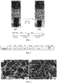
- the figure 1 presents the scheme of the process of formation of gels with different diamines used as reductant.
- a piece of graphene monolith decorated with gold nanoparticles as obtained in Examples 1, 2 or 3 is placed in a quartz crucible placed in the center of an LPCVD furnace.
- the growth is carried out at a temperature of around 650 ° C. with a reactive gas SiH 4 (flow rate approximately 40 cm 3 / min), an additional gas HCl (flow rate at about 100 cm 3 / min) and a carrier gas H 2 (flow rate at about 1L / min).
- the total working pressure is about 6 Torr.
- the reaction time is about 20 minutes. This last criterion is only important for the length of the silicon nanowires.
- the GH-HD graphene monoliths as obtained in Example 4 are cut into several slices approximately 1 mm thick. Two slices of the monolith, of the same mass, are pressed on nickel foams under a pressure of 10 MPa. A piece of filter paper (Whatman filter paper) was used as a separator between the electrodes. Electrodes and filter paper, quenched overnight in 6M KOH electrolyte, were assembled in a layered structure in a Swagelok-type two-electrode cell configuration with stainless steel as the current collector. .
- Example 6 The supercapacity performance of Example 6 was evaluated using cyclic voltammetry, galvanostatic charge-discharge cycles, and electrochemical impedance spectroscopy.
- VMP3 multi-channel potentiostat / galvanostat equipped with EC-Lab software has been used for all electrochemical techniques.
- the cyclic voltammetry and charge-discharge measurements were made between 0 and 1 V with scanning rates of 100 mV / s at 1000 mV / s and 0.5 A / g at 100 A / g respectively.
- the electrochemical impedance spectroscopy test was carried out in a frequency range between 400 kHz and 40 mHz and a AC disturbance of 10 mV.
- C vol C wt x ⁇ , where ⁇ is the packing density of graphene.
- Conditioning densities were obtained by calculating the dried gel mass with an accuracy of 0.01 mg and measuring the dimensions using scanning electron microscopy.
- a Metler-Toledo weigh scale XPE205 was used to obtain the weight of the samples with an accuracy of 0.01 mg.
- XRD Wide Angle X-Ray Diffraction
- TGA Thermogravimetric analysis
- Conditioning densities were also calculated by measuring the mass and volume of these films.
- the global spectra of photoelectrons were recorded with a passage energy of 117 eV and high resolution spectra with a pass energy of 23.5 eV.
- Deconvolution of the C1s and N1s level spectra was performed by fitting the individual components to values obtained from previous reports using the Casa XPS software.
- the spectra were adjusted in Gauss-Lorentz curves with maximum values of total width less than 1.5 in all cases.
- the morphology of graphene monoliths was characterized using a Zeiss Ultra 55 electron microscope at an acceleration voltage of 7 kV.
- the physical and chemical properties of the GH-HD graphene monoliths of Example 4 were characterized by FT-IR, TGA, XRD, XPS and conductivity measurements. Scanning electron microscopy was performed to analyze the three-dimensional structures.
- the synthesized GH-HD therefore has a high degree of reduction with a significant C / O ratio of 16.7 (cf. Figure 2 ), an interlayer spacing of 3.76 ⁇ and a thermal behavior identical to graphite.
- GH-HD has a porous morphology (cf. Figure 3 ) and has a high specific surface area of 1433 m 2 / g.
- the macroporous network also allows a high conductivity of GH-HD of 1141 S / m (cf. Figure 2 ).
- the synthesized GH-HD has a low 0.62 ⁇ charge transfer resistance offering real high-speed performance.
- the synthesis process according to the invention is very simple, in one step, and makes it possible to obtain these very small graphene monoliths which are likely to be used in lithium ion batteries and low cost supercapacitors having high powers.
- the synthesized GH-HD was tested in a supercapacitor configuration according to Example 6.
- the synthesized GH-HD in supercapacity configuration, demonstrates high capacities of 190 F / g at a current density of 0.5 A / g and 123 F / g at a current density of 100 A / g (cf. . Figure 2 ).
- GH-HD in supercapacity configuration offers a high power density of 38 kW / kg while providing an energy density of 4.3 Wh / kg (cf. Figure 4 ).
- GH-HD thus exceeds the graphene monoliths obtained by reduction of graphene oxide by hydrothermal treatment, heat treatment and L-glutathione.
- GH-HD in supercapacity configuration exhibits excellent cyclic stability with a 93% capacity retention observed after 2,000 cycles at a high current density of 10 A / g. Full capacity retention was observed after 5,000 cycles at a current density of 2 A / g (cf. Figure 5 ).
- CMG Graphene oxide reduced to gaseous hydrazine
- CMG has an electrical conductivity of 1,832 S / m, which is higher than that of GH-HD (1,141 S / m); this can be understood by improving the reduction in homogenized reaction media.
- the Figure 6 shows the specific capacity of GH-HD and CMG, depending on the current density.
- GH-HD-AD GH-HD densified gel
- the GH-HD was densified from a density of 0.58 g / cm 3 to 1.56 g / cm 3 by drying under ambient conditions. The gradual removal of the water molecules from the inter-layer spaces reduces the gel to nearly one-tenth of its original size.
- the Figure 7 shows the cyclic stability of GH-HD and its densified counterpart GH-HD-AD at a current density of 2 A / g.
- GH-HD-AD provides gravimetric and volumetric discharge capacities of 130 F / g and 200 F / cm3 respectively at a high current density of 2 A / g.
- volumetric capacity is considered a crucial measure for compact portable applications.
- a simple drying technique it is possible to double the volumetric capacity of freeze-dried GH-HD from 110 F / cm 3 to 257 F / cm 3 at a current density of 0.5 A / g.
Landscapes
- Chemical & Material Sciences (AREA)
- Engineering & Computer Science (AREA)
- Chemical Kinetics & Catalysis (AREA)
- Materials Engineering (AREA)
- Ceramic Engineering (AREA)
- General Chemical & Material Sciences (AREA)
- Electrochemistry (AREA)
- Manufacturing & Machinery (AREA)
- Power Engineering (AREA)
- Structural Engineering (AREA)
- Organic Chemistry (AREA)
- Inorganic Chemistry (AREA)
- Microelectronics & Electronic Packaging (AREA)
- Composite Materials (AREA)
- Nanotechnology (AREA)
- Dispersion Chemistry (AREA)
- Carbon And Carbon Compounds (AREA)
Applications Claiming Priority (1)
| Application Number | Priority Date | Filing Date | Title |
|---|---|---|---|
| EP17305530 | 2017-05-10 |
Publications (1)
| Publication Number | Publication Date |
|---|---|
| EP3401293A1 true EP3401293A1 (de) | 2018-11-14 |
Family
ID=58994870
Family Applications (1)
| Application Number | Title | Priority Date | Filing Date |
|---|---|---|---|
| EP18171455.1A Withdrawn EP3401293A1 (de) | 2017-05-10 | 2018-05-09 | Herstellungsverfahren eines verbundwerkstoffs aus einem monolithen aus graphen und silizium |
Country Status (2)
| Country | Link |
|---|---|
| US (1) | US20180331350A1 (de) |
| EP (1) | EP3401293A1 (de) |
Cited By (2)
| Publication number | Priority date | Publication date | Assignee | Title |
|---|---|---|---|---|
| CN112830482A (zh) * | 2020-12-31 | 2021-05-25 | 宁波杉杉新材料科技有限公司 | 石墨包覆剂、包覆改性石墨材料、电池及其制备和应用 |
| CN117673461A (zh) * | 2023-12-01 | 2024-03-08 | 东莞市创明电池技术有限公司 | 固态聚合物电解质及其制备方法、及于二次电池中的应用 |
Families Citing this family (6)
| Publication number | Priority date | Publication date | Assignee | Title |
|---|---|---|---|---|
| US20200365895A1 (en) * | 2018-02-09 | 2020-11-19 | Sekisui Chemical Co., Ltd. | Carbon material, electrode for electricity storage devices, electricity storage device, and nonaqueous electrolyte secondary battery |
| CN108610051B (zh) * | 2018-07-18 | 2021-05-11 | 东北林业大学 | 一种改性木质基碳化硅陶瓷材料的制备方法 |
| CN109847661B (zh) * | 2019-01-28 | 2021-12-14 | 合肥工业大学 | 一种氧化石墨烯与银纳米线组装三元弹性水凝胶的制备方法 |
| CN111370665A (zh) * | 2020-03-19 | 2020-07-03 | 西安越遴新材料研究院有限公司 | 一种高比容量多片层堆叠状硅碳复合材料的制备方法 |
| CN111508717B (zh) * | 2020-03-27 | 2022-02-08 | 江苏大学 | 新型三维硅结构超级电容器电极材料及其制备方法 |
| CN114551818B (zh) * | 2021-07-08 | 2023-10-03 | 万向一二三股份公司 | 一种纳米硅复合颗粒、负极片和固体锂电池 |
Citations (1)
| Publication number | Priority date | Publication date | Assignee | Title |
|---|---|---|---|---|
| US20160043384A1 (en) * | 2014-08-07 | 2016-02-11 | Aruna Zhamu | Graphene foam-protected anode active materials for lithium batteries |
-
2018
- 2018-05-09 EP EP18171455.1A patent/EP3401293A1/de not_active Withdrawn
- 2018-05-10 US US15/976,201 patent/US20180331350A1/en not_active Abandoned
Patent Citations (1)
| Publication number | Priority date | Publication date | Assignee | Title |
|---|---|---|---|---|
| US20160043384A1 (en) * | 2014-08-07 | 2016-02-11 | Aruna Zhamu | Graphene foam-protected anode active materials for lithium batteries |
Non-Patent Citations (7)
| Title |
|---|
| BIN WANG ET AL: "Adaptable Silicon-Carbon Nanocables Sandwiched between Reduced Graphene Oxide Sheets as Lithium Ion Battery Anodes", ACS NANO, vol. 7, no. 2, 26 February 2013 (2013-02-26), US, pages 1437 - 1445, XP055306035, ISSN: 1936-0851, DOI: 10.1021/nn3052023 * |
| JIAN-GUO REN ET AL: "A silicon nanowire-reduced graphene oxide composite as a high-performance lithium ion battery anode material", NANOSCALE, vol. 6, no. 6, 1 January 2014 (2014-01-01), United Kingdom, pages 3353, XP055425708, ISSN: 2040-3364, DOI: 10.1039/c3nr05093a * |
| JIE HUANG ET AL: "Nanocomposites of size-controlled gold nanoparticles and graphene oxide: Formation and applications in SERS and catalysis", NANOSCALE, vol. 2, no. 12, 1 January 2010 (2010-01-01), United Kingdom, pages 2733, XP055425695, ISSN: 2040-3364, DOI: 10.1039/c0nr00473a * |
| NECIP ATAR ET AL: "Magnetic iron oxide and iron oxide@gold nanoparticle anchored nitrogen and sulfur-functionalized reduced graphene oxide electrocatalyst for methanol oxidation", RSC ADVANCES: AN INTERNATIONAL JOURNAL TO FURTHER THE CHEMICAL SCIENCES, vol. 5, no. 33, 1 January 2015 (2015-01-01), GB, pages 26402 - 26409, XP055425699, ISSN: 2046-2069, DOI: 10.1039/C5RA03735B * |
| SU-TING HAN ET AL: "Layer-by-Layer-Assembled Reduced Graphene Oxide/Gold Nanoparticle Hybrid Double-Floating-Gate Structure for Low-Voltage Flexible Flash Memory", ADVANCED MATERIALS, vol. 25, no. 6, 5 November 2012 (2012-11-05), pages 872 - 877, XP055125227, ISSN: 0935-9648, DOI: 10.1002/adma.201203509 * |
| TH STELZNER ET AL: "Growth of silicon nanowires by chemical vapour deposition on gold implanted silicon substrates", NANOTECHNOLOGY, IOP, BRISTOL, GB, vol. 17, no. 12, 28 June 2006 (2006-06-28), pages 2895 - 2898, XP020103799, ISSN: 0957-4484, DOI: 10.1088/0957-4484/17/12/012 * |
| ZHIQIANG NIU ET AL: "A Leavening Strategy to Prepare Reduced Graphene Oxide Foams", ADVANCED MATERIALS, vol. 24, no. 30, 8 August 2012 (2012-08-08), pages 4144 - 4150, XP055769292, ISSN: 0935-9648, DOI: 10.1002/adma.201200197 * |
Cited By (3)
| Publication number | Priority date | Publication date | Assignee | Title |
|---|---|---|---|---|
| CN112830482A (zh) * | 2020-12-31 | 2021-05-25 | 宁波杉杉新材料科技有限公司 | 石墨包覆剂、包覆改性石墨材料、电池及其制备和应用 |
| CN112830482B (zh) * | 2020-12-31 | 2022-10-04 | 宁波杉杉新材料科技有限公司 | 石墨包覆剂、包覆改性石墨材料、电池及其制备和应用 |
| CN117673461A (zh) * | 2023-12-01 | 2024-03-08 | 东莞市创明电池技术有限公司 | 固态聚合物电解质及其制备方法、及于二次电池中的应用 |
Also Published As
| Publication number | Publication date |
|---|---|
| US20180331350A1 (en) | 2018-11-15 |
Similar Documents
| Publication | Publication Date | Title |
|---|---|---|
| EP3401293A1 (de) | Herstellungsverfahren eines verbundwerkstoffs aus einem monolithen aus graphen und silizium | |
| Qi et al. | Suitable thickness of carbon coating layers for silicon anode | |
| EP3177651B1 (de) | Oberflächenmodifiziertes hydrophiles kohlenstoffhaltiges material | |
| JP7771273B2 (ja) | シリコン-炭素複合材料および方法 | |
| JP7507086B2 (ja) | 炭素被覆酸化ケイ素/黒鉛複合粒子、製造方法、及びその用途 | |
| EP2231516B1 (de) | Aerogele von Kohlenstoffnanoröhrchen | |
| US20210114886A1 (en) | Silicon-carbon nanomaterials, method of making same, and uses of same | |
| CN120933339A (zh) | 用于金属离子电池的电活性材料 | |
| US10020500B2 (en) | Carbonized polyaniline-grafted silicon nanoparticles encapsulated in graphene sheets for li-ion battery anodes | |
| Krüner et al. | Silicon oxycarbide beads from continuously produced polysilsesquioxane as stable anode material for lithium-ion batteries | |
| KR20220062552A (ko) | 금속이온 배터리에 사용하기 위한 전기 활성 물질 | |
| Yang et al. | Sealing porous carbon via surface-initiated polymerization achieves low-surface-area Si-C microparticles for Li-ion batteries | |
| EP3659193A1 (de) | Nanostrukturiertes material und verfahren zur herstellung davon | |
| WO2020109505A1 (fr) | Electrolyte polymere conducteur pour batteries | |
| FR3142468A1 (fr) | Sélénium immobilisé sur du carbone poreux en présence d'oxygène, procédé de fabrication et utilisations de sélénium immobilisé dans une batterie rechargeable | |
| Shi et al. | Facile synthesis of structure-controllable, N-doped graphene aerogels and their application in supercapacitors | |
| BE1032343A1 (fr) | Composites silicium-carbone pour les anodes de batteries lithium-ion | |
| CN116675216B (zh) | 一种复合硬碳的制备方法及其在钠离子电池中的应用 | |
| Yao et al. | Tri-isolation and tri-conductive Si/CuCo-NC@ rGO hierarchical architecture enabling highly stable and fast-kinetic silicon anodes for lithium-ion batteries | |
| WO2010063907A2 (fr) | Procedes de preparation et de depot de particules a l'echelle nanometrique ou angstromique sur supports | |
| Fattahimoghaddam et al. | Hydrothermal Carbonaceous Carbon-Polydimethylsiloxane Nanocomposites: Emerging Potential in Light-Driven Thermoelectric and Photothermal Conversion Applications |
Legal Events
| Date | Code | Title | Description |
|---|---|---|---|
| PUAI | Public reference made under article 153(3) epc to a published international application that has entered the european phase |
Free format text: ORIGINAL CODE: 0009012 |
|
| STAA | Information on the status of an ep patent application or granted ep patent |
Free format text: STATUS: THE APPLICATION HAS BEEN PUBLISHED |
|
| AK | Designated contracting states |
Kind code of ref document: A1 Designated state(s): AL AT BE BG CH CY CZ DE DK EE ES FI FR GB GR HR HU IE IS IT LI LT LU LV MC MK MT NL NO PL PT RO RS SE SI SK SM TR |
|
| AX | Request for extension of the european patent |
Extension state: BA ME |
|
| STAA | Information on the status of an ep patent application or granted ep patent |
Free format text: STATUS: REQUEST FOR EXAMINATION WAS MADE |
|
| 17P | Request for examination filed |
Effective date: 20190514 |
|
| RBV | Designated contracting states (corrected) |
Designated state(s): AL AT BE BG CH CY CZ DE DK EE ES FI FR GB GR HR HU IE IS IT LI LT LU LV MC MK MT NL NO PL PT RO RS SE SI SK SM TR |
|
| STAA | Information on the status of an ep patent application or granted ep patent |
Free format text: STATUS: EXAMINATION IS IN PROGRESS |
|
| 17Q | First examination report despatched |
Effective date: 20210217 |
|
| STAA | Information on the status of an ep patent application or granted ep patent |
Free format text: STATUS: THE APPLICATION IS DEEMED TO BE WITHDRAWN |
|
| 18D | Application deemed to be withdrawn |
Effective date: 20210629 |