EP3401223B1 - Système de refroidissement de moteur par air de la cabine - Google Patents
Système de refroidissement de moteur par air de la cabine Download PDFInfo
- Publication number
- EP3401223B1 EP3401223B1 EP18171633.3A EP18171633A EP3401223B1 EP 3401223 B1 EP3401223 B1 EP 3401223B1 EP 18171633 A EP18171633 A EP 18171633A EP 3401223 B1 EP3401223 B1 EP 3401223B1
- Authority
- EP
- European Patent Office
- Prior art keywords
- air
- cabin
- compressor
- motor
- cooling
- Prior art date
- Legal status (The legal status is an assumption and is not a legal conclusion. Google has not performed a legal analysis and makes no representation as to the accuracy of the status listed.)
- Active
Links
- 238000001816 cooling Methods 0.000 title claims description 114
- IJGRMHOSHXDMSA-UHFFFAOYSA-N Atomic nitrogen Chemical compound N#N IJGRMHOSHXDMSA-UHFFFAOYSA-N 0.000 claims description 50
- 229910052757 nitrogen Inorganic materials 0.000 claims description 25
- 230000001105 regulatory effect Effects 0.000 claims description 21
- 238000000034 method Methods 0.000 claims description 12
- 239000002828 fuel tank Substances 0.000 claims description 10
- 238000000926 separation method Methods 0.000 claims description 10
- 230000007613 environmental effect Effects 0.000 claims description 9
- XLYOFNOQVPJJNP-UHFFFAOYSA-N water Substances O XLYOFNOQVPJJNP-UHFFFAOYSA-N 0.000 description 5
- QVGXLLKOCUKJST-UHFFFAOYSA-N atomic oxygen Chemical compound [O] QVGXLLKOCUKJST-UHFFFAOYSA-N 0.000 description 3
- 230000006837 decompression Effects 0.000 description 3
- 239000007789 gas Substances 0.000 description 3
- 238000002955 isolation Methods 0.000 description 3
- 239000001301 oxygen Substances 0.000 description 3
- 229910052760 oxygen Inorganic materials 0.000 description 3
- 238000004804 winding Methods 0.000 description 3
- 230000000740 bleeding effect Effects 0.000 description 2
- 230000001143 conditioned effect Effects 0.000 description 1
- 230000001419 dependent effect Effects 0.000 description 1
- 239000000463 material Substances 0.000 description 1
- 238000012986 modification Methods 0.000 description 1
- 230000004048 modification Effects 0.000 description 1
Images

Classifications
-
- B—PERFORMING OPERATIONS; TRANSPORTING
- B64—AIRCRAFT; AVIATION; COSMONAUTICS
- B64D—EQUIPMENT FOR FITTING IN OR TO AIRCRAFT; FLIGHT SUITS; PARACHUTES; ARRANGEMENT OR MOUNTING OF POWER PLANTS OR PROPULSION TRANSMISSIONS IN AIRCRAFT
- B64D13/00—Arrangements or adaptations of air-treatment apparatus for aircraft crew or passengers, or freight space, or structural parts of the aircraft
- B64D13/06—Arrangements or adaptations of air-treatment apparatus for aircraft crew or passengers, or freight space, or structural parts of the aircraft the air being conditioned
-
- H—ELECTRICITY
- H02—GENERATION; CONVERSION OR DISTRIBUTION OF ELECTRIC POWER
- H02K—DYNAMO-ELECTRIC MACHINES
- H02K9/00—Arrangements for cooling or ventilating
- H02K9/02—Arrangements for cooling or ventilating by ambient air flowing through the machine
- H02K9/04—Arrangements for cooling or ventilating by ambient air flowing through the machine having means for generating a flow of cooling medium
-
- B—PERFORMING OPERATIONS; TRANSPORTING
- B64—AIRCRAFT; AVIATION; COSMONAUTICS
- B64D—EQUIPMENT FOR FITTING IN OR TO AIRCRAFT; FLIGHT SUITS; PARACHUTES; ARRANGEMENT OR MOUNTING OF POWER PLANTS OR PROPULSION TRANSMISSIONS IN AIRCRAFT
- B64D13/00—Arrangements or adaptations of air-treatment apparatus for aircraft crew or passengers, or freight space, or structural parts of the aircraft
- B64D13/02—Arrangements or adaptations of air-treatment apparatus for aircraft crew or passengers, or freight space, or structural parts of the aircraft the air being pressurised
-
- B—PERFORMING OPERATIONS; TRANSPORTING
- B64—AIRCRAFT; AVIATION; COSMONAUTICS
- B64D—EQUIPMENT FOR FITTING IN OR TO AIRCRAFT; FLIGHT SUITS; PARACHUTES; ARRANGEMENT OR MOUNTING OF POWER PLANTS OR PROPULSION TRANSMISSIONS IN AIRCRAFT
- B64D13/00—Arrangements or adaptations of air-treatment apparatus for aircraft crew or passengers, or freight space, or structural parts of the aircraft
- B64D13/06—Arrangements or adaptations of air-treatment apparatus for aircraft crew or passengers, or freight space, or structural parts of the aircraft the air being conditioned
- B64D13/08—Arrangements or adaptations of air-treatment apparatus for aircraft crew or passengers, or freight space, or structural parts of the aircraft the air being conditioned the air being heated or cooled
-
- B—PERFORMING OPERATIONS; TRANSPORTING
- B64—AIRCRAFT; AVIATION; COSMONAUTICS
- B64D—EQUIPMENT FOR FITTING IN OR TO AIRCRAFT; FLIGHT SUITS; PARACHUTES; ARRANGEMENT OR MOUNTING OF POWER PLANTS OR PROPULSION TRANSMISSIONS IN AIRCRAFT
- B64D37/00—Arrangements in connection with fuel supply for power plant
- B64D37/32—Safety measures not otherwise provided for, e.g. preventing explosive conditions
-
- F—MECHANICAL ENGINEERING; LIGHTING; HEATING; WEAPONS; BLASTING
- F25—REFRIGERATION OR COOLING; COMBINED HEATING AND REFRIGERATION SYSTEMS; HEAT PUMP SYSTEMS; MANUFACTURE OR STORAGE OF ICE; LIQUEFACTION SOLIDIFICATION OF GASES
- F25B—REFRIGERATION MACHINES, PLANTS OR SYSTEMS; COMBINED HEATING AND REFRIGERATION SYSTEMS; HEAT PUMP SYSTEMS
- F25B13/00—Compression machines, plants or systems, with reversible cycle
-
- F—MECHANICAL ENGINEERING; LIGHTING; HEATING; WEAPONS; BLASTING
- F25—REFRIGERATION OR COOLING; COMBINED HEATING AND REFRIGERATION SYSTEMS; HEAT PUMP SYSTEMS; MANUFACTURE OR STORAGE OF ICE; LIQUEFACTION SOLIDIFICATION OF GASES
- F25B—REFRIGERATION MACHINES, PLANTS OR SYSTEMS; COMBINED HEATING AND REFRIGERATION SYSTEMS; HEAT PUMP SYSTEMS
- F25B31/00—Compressor arrangements
- F25B31/02—Compressor arrangements of motor-compressor units
- F25B31/026—Compressor arrangements of motor-compressor units with compressor of rotary type
-
- H—ELECTRICITY
- H02—GENERATION; CONVERSION OR DISTRIBUTION OF ELECTRIC POWER
- H02K—DYNAMO-ELECTRIC MACHINES
- H02K7/00—Arrangements for handling mechanical energy structurally associated with dynamo-electric machines, e.g. structural association with mechanical driving motors or auxiliary dynamo-electric machines
- H02K7/14—Structural association with mechanical loads, e.g. with hand-held machine tools or fans
-
- B—PERFORMING OPERATIONS; TRANSPORTING
- B64—AIRCRAFT; AVIATION; COSMONAUTICS
- B64D—EQUIPMENT FOR FITTING IN OR TO AIRCRAFT; FLIGHT SUITS; PARACHUTES; ARRANGEMENT OR MOUNTING OF POWER PLANTS OR PROPULSION TRANSMISSIONS IN AIRCRAFT
- B64D13/00—Arrangements or adaptations of air-treatment apparatus for aircraft crew or passengers, or freight space, or structural parts of the aircraft
- B64D13/06—Arrangements or adaptations of air-treatment apparatus for aircraft crew or passengers, or freight space, or structural parts of the aircraft the air being conditioned
- B64D2013/0603—Environmental Control Systems
- B64D2013/0618—Environmental Control Systems with arrangements for reducing or managing bleed air, using another air source, e.g. ram air
-
- B—PERFORMING OPERATIONS; TRANSPORTING
- B64—AIRCRAFT; AVIATION; COSMONAUTICS
- B64D—EQUIPMENT FOR FITTING IN OR TO AIRCRAFT; FLIGHT SUITS; PARACHUTES; ARRANGEMENT OR MOUNTING OF POWER PLANTS OR PROPULSION TRANSMISSIONS IN AIRCRAFT
- B64D13/00—Arrangements or adaptations of air-treatment apparatus for aircraft crew or passengers, or freight space, or structural parts of the aircraft
- B64D13/06—Arrangements or adaptations of air-treatment apparatus for aircraft crew or passengers, or freight space, or structural parts of the aircraft the air being conditioned
- B64D2013/0603—Environmental Control Systems
- B64D2013/0644—Environmental Control Systems including electric motors or generators
-
- B—PERFORMING OPERATIONS; TRANSPORTING
- B64—AIRCRAFT; AVIATION; COSMONAUTICS
- B64D—EQUIPMENT FOR FITTING IN OR TO AIRCRAFT; FLIGHT SUITS; PARACHUTES; ARRANGEMENT OR MOUNTING OF POWER PLANTS OR PROPULSION TRANSMISSIONS IN AIRCRAFT
- B64D13/00—Arrangements or adaptations of air-treatment apparatus for aircraft crew or passengers, or freight space, or structural parts of the aircraft
- B64D13/06—Arrangements or adaptations of air-treatment apparatus for aircraft crew or passengers, or freight space, or structural parts of the aircraft the air being conditioned
- B64D2013/0603—Environmental Control Systems
- B64D2013/0648—Environmental Control Systems with energy recovery means, e.g. using turbines
-
- B—PERFORMING OPERATIONS; TRANSPORTING
- B64—AIRCRAFT; AVIATION; COSMONAUTICS
- B64D—EQUIPMENT FOR FITTING IN OR TO AIRCRAFT; FLIGHT SUITS; PARACHUTES; ARRANGEMENT OR MOUNTING OF POWER PLANTS OR PROPULSION TRANSMISSIONS IN AIRCRAFT
- B64D13/00—Arrangements or adaptations of air-treatment apparatus for aircraft crew or passengers, or freight space, or structural parts of the aircraft
- B64D13/06—Arrangements or adaptations of air-treatment apparatus for aircraft crew or passengers, or freight space, or structural parts of the aircraft the air being conditioned
- B64D2013/0603—Environmental Control Systems
- B64D2013/0688—Environmental Control Systems with means for recirculating cabin air
-
- Y—GENERAL TAGGING OF NEW TECHNOLOGICAL DEVELOPMENTS; GENERAL TAGGING OF CROSS-SECTIONAL TECHNOLOGIES SPANNING OVER SEVERAL SECTIONS OF THE IPC; TECHNICAL SUBJECTS COVERED BY FORMER USPC CROSS-REFERENCE ART COLLECTIONS [XRACs] AND DIGESTS
- Y02—TECHNOLOGIES OR APPLICATIONS FOR MITIGATION OR ADAPTATION AGAINST CLIMATE CHANGE
- Y02T—CLIMATE CHANGE MITIGATION TECHNOLOGIES RELATED TO TRANSPORTATION
- Y02T50/00—Aeronautics or air transport
- Y02T50/50—On board measures aiming to increase energy efficiency
Definitions
- the present disclosure relates to cooling of electric motors used on aircraft. More specifically, the present disclosure relates to motor cooling utilizing cabin air.
- Electric motors are used on aircraft to drive compressors to compress air for use in systems that control the flow of air through the aircraft.
- cabin air compressors that are used to compress air to be delivered to an air cycle machine. Air cycle machines are used in environmental control systems to condition air for delivery to the aircraft cabin.
- Cabin air compressors include an electric motor that is connected to a compressor via a shaft to drive the compressor.
- motor driven compressors that are used to compress air to be delivered to a nitrogen generation system. Nitrogen generation systems are used to produce nitrogen enriched air for delivery to a fuel tank for fuel tank inerting.
- motor driven compressors include an electric motor that is connected to two compressors via a shaft to drive both of the two compressors.
- Electric motors generate significant heat and need to be cooled.
- the first method includes using ram air to cool the motor.
- Ram air is air that is scooped from a ram air duct on the skin of an aircraft for use as cooling air on the aircraft. Scooping air through a ram air duct creates drag on the skin of the aircraft, reducing the overall efficiency of the aircraft. Further, the temperature of ram air is dependent on the altitude at which the aircraft is flying and can change significantly during a flight.
- the second method includes using air from the compressor that is being driven by the motor to cool the motor.
- Air will be drawn in and compressed with the compressor and then some of the compressed air will be bled, then cooled (typically by passing it through a heat exchanger) before being passed to cool the motor. Bleeding air from the compressed air reduces the efficiency of the compressor. Further, the compressed air will be heated when it is compressed and will not be significantly cooler than the temperature of the motor. The temperature of the motor cooling air will be a function of heat exchanger cooling capability, which typically utilizes ram air to cool. Utilizing ram air in this means adds additional drag to the aircraft as mentioned above.
- EP 1 806 288 A2 relates to cooling of motors.
- a cabin air cooling system for an aircraft is disclosed, according to appended claim 1.
- a method of cooling a motor of a rotary machine of an aircraft is disclosed, according to appended claim 6.
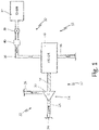
- FIG. 1 is a schematic view of cabin air cooling system 10.
- Cabin air cooling system 10 includes rotary machine 12, compressor 14, motor 16, shaft 18, compressor rotor 20, primary flow path 22, inlet 24, primary air ducts 26 and 28, secondary cooling flow path 30, cabin 32, cooling air ducts 34 and 36, shut-off valve 38, and pressure regulating device 40.
- Cabin air cooling system 10 includes rotary machine 12.
- Rotary machine 12 includes compressor 14 and motor 16.
- Motor 16 is connected to compressor 14 with shaft 18.
- Compressor 14 includes compressor rotor 20.
- Compressor rotor 20 is mounted on shaft 18 and motor 16 drives compressor 14 by rotating compressor rotor 20 with shaft 18.
- Motor 16 includes a rotor and a stator.
- Primary flow path 22 is a first flow path through rotary machine 12. Primary flow path 22 extends from inlet 24 to a second location in the aircraft. Primary flow path 22 includes primary air ducts 26 and 28. Primary air duct 26 extends between inlet 24 and compressor rotor 20. Primary air duct 28 extends from compressor rotor 20 to a second location in the aircraft. Air will enter primary flow path 22 through inlet 24. Inlet 24 draws air from an ambient unpressurized source exterior of the aircraft or from a pressurized bleed source on an aircraft, such as from the gas turbine engine, the cabin, or the cargo bay. The air that enters inlet 24 will flow through primary air duct 26 to compressor rotor 20. Compressor rotor 20 will compress the air and the compressed air will then flow through primary air duct 28. Primary air duct 28 will deliver the compressed air to a second location in the aircraft where compressed air is desired.
- Secondary cooling flow path 30 is a second flow path through rotary machine 12. Secondary cooling flow path 30 extends from cabin 32 to a location overboard the aircraft. Secondary cooling flow path 30 includes cooling air ducts 34 and 36. Cooling air duct 34 extends from cabin 32 to motor 16. Cooling air duct 36 extends from motor 16 to a location overboard the aircraft. Air will enter secondary cooling flow path 30 from cabin 32. The cabin air from cabin 32 will flow through first cooling air duct 34 to motor 16. The cabin air will flow through the stator windings of motor 16 to cool motor 16. The cabin air will then flow through cooling air duct 36. Cooling air duct 36 will dump the cabin air overboard.
- Shut-off valve 38 is positioned in cooling air duct 34 adjacent to cabin 32.
- Shut-off valve 38 isolates the flow of air from cabin 32 into secondary cooling flow path 30. This isolation valve is required in the event of a cabin decompression event, or where the system does may be off and no motor cooling flow is required.
- Cabin 32 on the aircraft will include a pressure regulating system to ensure that the pressure in cabin 32 stays at a sufficient level.
- Shut-off valve 38 can be an electrical valve, a pneumatic valve, or any other suitable valve.
- Shut-off valve 38 will move between a first position where air will not be routed out of cabin 32 to secondary cooling air flow 30 and a second position where air can be routed from cabin 32 to secondary cooling air flow 30.
- Shut-off valve 38 can be moved to the first position where air is not routed out of cabin 32 if there is a pressure loss in cabin 32.
- pressure regulating device 40 is positioned between shut-off valve 38 and motor 16. Pressure regulating device 40 regulates the pressure of the air flowing from cabin 32 through motor 16. For example, pressure regulative device 40 can regulate the pressure of the cooling air so that it is flowing through secondary flow system 30 at a pressure of about 69.9 kPa (10 pounds per square inch absolute (psia)). As cabin air from cabin 32 is kept at about 84.1 kPa (12.2 pounds per square inch absolute (psia)), regulating the flow of cabin air to 68.9 kPa (10 pounds per square inch absolute (psia)) ensures that there is good cabin air flow through secondary cooling system 30 at any given time. In alternate embodiments which do not fall within the scope of the invention as defined by the appended claims, cabin air cooling system 10 does not include pressure regulating device 40.
- the air from cabin 32 varies in pressure depending on whether the aircraft is on the ground, changing altitude during takeoff or landing, or at a cruising altitude.
- the pressure in cabin 32 is about 101.4 kPa (14.7 pounds per square inch absolute (psia)), which is the same pressure of an ambient outside of the aircraft.
- the pressure of the ambient outside of the aircraft will be lower.
- the pressure of the ambient outside of the aircraft will be about 13.8-20.7 kPa (2-3 pounds per square inch absolute (psia)). Due to the low pressure of an ambient outside of the aircraft at cruising altitude, cabin 32 has to be pressurized.
- the pressure in cabin 32 is kept at about 84.1 kPa (12.2 pounds per square inch absolute (psia)).
- Cabin 32 also has to be pressurized during takeoff and landing, as the pressure of the ambient outside of the aircraft will change as the aircraft gains or losses altitude during takeoff and landing.
- the air in the ambient outside of the aircraft will be at a lower pressure than the pressure in cabin 32, as cabin 32 is pressurized during flight. This will cause a pressure differential between cabin 32 and the ambient outside of the aircraft.
- the pressure differential will cause air to flow from cabin 32 to motor 16 through secondary cooling flow path 30.
- cabin air to cool motor 16 is advantageous. Bleeding the air from cabin 32 for use as cooling air does not create any efficiency losses for the aircraft, as some of the air in cabin 32 is typically routed to be dumped overboard. Routing this air through secondary cooling flow path 30 prior to dumping it overboard does not create any efficiency losses for the aircraft. Further, the air in cabin 32 is kept at a constant temperature for comfort during flight, thus the cabin air that is bled into second cooling flow path 30 will be at a constant temperature. Typically, the temperature in cabin 32 is about 294 to 297 K (70 to 75 degrees Fahrenheit). The temperature in motor 16 will be about 422 to 450 K (300 to 350 degrees Fahrenheit).
- the cabin air is at a much lower temperature than the temperature of motor 16 and will provide good cooling for motor 16.
- pressure regulating device 40 regulates the pressure of the air from cabin 32 that flows through secondary cooling flow path 30 into motor 16. Having a consistent pressure can ensure that there is good cooling airflow through motor 16.
- air that has been compressed with compressor 14 creates an efficiency loss in compressor 14, as work is being done to compress air only to use the air for cooling. Further, air that is compressed with compressor 14 will be at a temperature of about 366 to 422 K (200 to 300 degrees Fahrenheit). As motor 16 is at about 422 to 450 K (300 to 350 degrees Fahrenheit), the air from compressor 14 will not provide significant cooling for motor 16. Using cabin air to cool motor 16 does not create any efficiency losses in compressor 14. Further, the cabin air is at a temperature of about 294 to 297 K (70 to 75 degrees Fahrenheit) and will provide better cooling for motor 16.
- FIG. 2 is a schematic view of cabin air cooling system 102 for use with cabin air compressor 106 in environmental control system 100.
- FIG. 2 shows environmental control system 100, cabin air cooling system 102, cabin 104, cabin air compressor 106, air cycle machine 108, ram air duct 110, compressor 112, motor 114, shaft 116, compressor rotor 118, fan 120, compressor 122, first turbine 124, second turbine 126, shaft 128, compressor rotor 130, first turbine rotor 132, second turbine rotor 134, primary heat exchanger 136, secondary heat exchanger 138, reheater 140, condenser 142, water collector 144, ram air inlet 146, ram air outlet 148, primary flow path 150, inlet 152, primary air ducts 156, 158, 160, 162, 164, 166, 168, 170, 172, and 174, secondary flow path 176, cooling air ducts 178 and 180, shut-off valve 182, and pressure regulating device 184.
- Environmental control system 100 can be mounted in an aircraft to supply conditioned air to the aircraft cabin at the proper temperature and pressure.
- Environmental control system 100 includes cabin air cooling system 102 that provides cabin air from cabin 104 to cabin air compressor 106.
- Cabin air compressor 106 compresses air and delivers the compressed air to air cycle machine 108.
- Air cycle machine 108 conditions the air and deliver the air to cabin 104.
- Ram air duct 110 is also included that supplies cooling air to air cycle machine 106 and then dumps the cooling air overboard.
- Cabin air compressor 106 includes compressor 112 and motor 114.
- Shaft 116 extends from motor 114 to compressor 112.
- Compressor rotor 118 of compressor 112 is mounted on shaft 116 and motor 114 drives compressor 112 by rotating compressor rotor 118 with shaft 116.
- Motor 114 includes a rotor and a stator.
- Air cycle machine 108 includes fan 120, compressor 122, first turbine 124, and second turbine 126. In the embodiment shown in FIG. 2 , air cycle machine 108 has two turbines. In alternate embodiments, air cycle machine 108 can have a single turbine. Shaft 128 extends from fan 120 to compressor 122 to first turbine 124 to second turbine 126. Compressor rotor 130 of compressor 122, first turbine rotor 132 of first turbine 124, and second turbine rotor 134 of second turbine 126 are mounted on shaft 128. Fan 120 is positioned in ram air duct 110. As air flows through air cycle machine 108, first turbine rotor 132 and second turbine rotor 134 impart work from the air and rotate shaft 128, thus rotating compressor rotor 130 and fan 120.
- Air cycle machine 108 also includes primary heat exchanger 136 and secondary heat exchanger 138.
- Primary heat exchanger 136 and secondary heat exchanger 138 are connected to one another.
- Reheater 140, condenser 142, and water collector 144 further form a part of air cycle machine 108.
- Primary heat exchanger 136 and secondary heat exchanger 138 are positioned in ram air duct 110.
- Primary heat exchanger 136 and secondary heat exchanger 138 are used to cool the compressed air that flows through environmental control system 100 using cooling ram air.
- Ram air is pulled into ram air duct 110 through ram air inlet 146 with fan 110 during operation on the ground or air is forced into ram air duct 110 during flight.
- the ram air flows across primary heat exchanger 136 and secondary heat exchanger 138 to cool the compressed air that flows through primary heat exchanger 136 and secondary heat exchanger 138.
- the used ram air is then dumped overboard through ram air outlet 148.
- Primary flow path 150 is a first flow path through cabin air compressor 106 and air cycle machine 108 of environmental control system 100. Air will enter primary flow path 150 through inlet 152. Inlet 152 draws air from an ambient unpressurized source exterior of the aircraft or from a pressurized bleed source on an aircraft, such as from the gas turbine engine, the cabin, or the cargo bay. The air that enters inlet 152 will flow through primary air duct 154 to compressor rotor 118. Compressor rotor 118 will compress the air. The compressed air will then flow through primary air duct 156 to primary heat exchanger 136.
- Primary heat exchanger 136 will cool the compressed air with cooling ram air. The cooled air will then flow through primary air duct 158 to compressor rotor 130. Compressor rotor 130 will further compress the air. The compressed air will then flow through primary air duct 160 to secondary heat exchanger 138. Secondary heat exchanger 138 will further cool the compressor air with cooling ram air.
- the cooled air from secondary heat exchanger 138 will then flow through primary air duct 162 to reheater 140 and condenser 142.
- Reheater 140 mixes the cooled air with recirculated air from cabin 104 to heat the cooled air.
- Condenser 142 condenses the cooled air by lowering the air temperature.
- the reheated and condensed air then flows through primary air duct 164 to water collector 144.
- Water collector 144 collects the condensed water out of the air.
- the air then flows through primary air duct 166 back through reheater 34.
- Air from reheater 140 then flows through primary air duct 168 through first turbine rotor 132.
- First turbine rotor 132 will extract energy from the air as the air expands as it flows across first turbine rotor 132. The energy extracted from the air is used to drive shaft 128.
- Secondary cooling flow path 176 is a second flow path through cabin air compressor 106. Secondary cooling flow path 176 extends from cabin 104 to ram air duct 110. Cooling air duct 178 extends from cabin 104 to motor 114. Cooling air duct 180 extends from motor 114 to ram air duct 110. Air will enter secondary cooling flow path 176 from cabin 104. The cabin air from cabin 104 will flow through first cooling air duct 178 to motor 114. The cabin air will flow through the stator windings of motor 114 to cool motor 114. The cabin air will then flow through cooling air duct 180 to ram air duct 110 to be dumped overboard through ram air outlet 148 with used ram air.
- Shut-off valve 182 is positioned in cooling air duct 178 adjacent to cabin 104. Shut-off valve 182 isolates the flow of air from cabin 104 into secondary cooling flow path 176. This isolation valve is required in the event of a cabin decompression event, or where the system does may be off and no motor cooling flow is required.
- Pressure regulating device 184 is also positioned in cooling air duct 178. Pressure regulating device 184 is positioned between shut-off valve 182 and motor 114. Pressure regulating device 184 regulates the pressure of the air flowing from cabin 104 through motor 114. In alternate embodiments which do not fall within the scope of the invention as defined by the appended claims, cabin air cooling system 102 does not include pressure regulating device 184.
- Cabin air from cabin 104 can be used to cool motor 114 in cabin air compressor 106. Cabin air does not create any efficiency losses for the aircraft, as the cabin air that is to be dumped overboard can be used to cool motor 114 before being dumped overboard. Further, cabin air is at a constant temperature of about 70 to 75 degrees Fahrenheit and provides good cooling of motor 114, which is at a temperature of about 300 to 350 degrees Fahrenheit. Additionally, during takeoff, landing, and at cruising altitude, there will be a pressure differential that provides a good flow of cooling air from cabin 104 to motor 114.
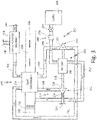
- FIG. 3 is a schematic view of cabin air cooling system 202 for use with motor driven compressor 206 in nitrogen generation system 200.
- FIG. 3 includes nitrogen generation system 200, cabin air cooling system 202, cabin 204, motor driven compressor 206, air separation module 208, ram air duct 210, first compressor 212, second compressor 214, motor 216, shaft 218, first compressor rotor 220, second compressor rotor 222, heat exchanger 224, ram air inlet 226, ram air fan 228, ram air outlet 230, primary flow path 232, inlet 234, primary air ducts 236, 238, 240, 242, 244, 246, and 247, secondary cooling flow path 248, cooling air ducts 250 and 252, shut-off valve 254, and pressure regulating device 256.
- Nitrogen generation system 200 includes motor driven compressor 206.
- Motor driven compressor 206 includes first compressor 212, second compressor 214, and motor 216.
- Shaft 218 extends from motor 216 to first compressor 212 and second compressor 214.
- First compressor rotor 220 and second compressor rotor 22 are mounted on shaft 218 and motor 216 drives first compressor 212 and second compressor 214 by rotating first compressor rotor 220 and second compressor rotor 222 about shaft 218.
- Motor 216 includes a rotor and a stator.
- Nitrogen generation system 200 further includes heat exchanger 224 and air separation module 208.
- Heat exchanger 224 is positioned in ram air duct 210. Heat exchanger 224 is used to cool the compressed air that flows through nitrogen generation system 200 using cooling ram air. Ram air is pulled into ram air duct 210 through ram air inlet 226 with ram air fan 228 during operation on the ground or air is forced into ram air duct 210 during flight. The ram air flows across heat exchanger 224 to cool the compressed air that flows through heat exchanger 224. The used ram air is then dumped overboard through ram air outlet 230.
- Primary flow path 232 is a first flow path through nitrogen generation system 200.
- Air will enter primary flow path 232 through inlet 234.
- Inlet 234 draws air from an ambient unpressurized source exterior of the aircraft or from a pressurized bleed source on an aircraft, such as from the gas turbine engine, the cabin, or the cargo bay.
- the air that enters inlet 234 will flow through primary air duct 236 to compressor rotor 220.
- Compressor rotor 220 will compress the air.
- the compressed air will then flow through primary air duct 238 to heat exchanger 224.
- Heat exchanger 224 will cool the compressed air with cooling ram air. The cooled air will then flow through primary air duct 240 to compressor rotor 222. Compressor rotor 222 will further compress the air. The compressed air will then flow through primary air duct 242 to heat exchanger 224. Heat exchanger 224 will further cool the compressed air with cooling ram air.
- Air separation module 208 will separate oxygen from the air, creating both oxygen enriched air and nitrogen enriched air.
- the nitrogen enriched air can then flow through primary air duct 246 to a fuel tank on the aircraft to be used for fuel tank inerting.
- the oxygen enriched air can flow through primary air duct 247 to be dumped overboard or used elsewhere on the aircraft.
- Secondary cooling flow path 248 is a second flow path through motor driven compressor 206. Secondary cooling flow path 248 extends from cabin 204 to ram air duct 210. Cooling air duct 250 extends from cabin 204 to motor 216. Cooling air duct 252 extends from motor 216 to ram air duct 210. Air will enter secondary cooling flow path 248 from cabin 204. The cabin air from cabin 204 will flow through first cooling air duct 250 to motor 216. The cabin air will flow through the stator windings of motor 216 to cool motor 216. The cabin air will then flow through cooling air duct 252 to ram air duct 210 to be dumped overboard through ram air outlet 230 with used ram air.
- Shut-off valve 254 is positioned in cooling air duct 250 adjacent to cabin 204.
- Shut-off valve 254 isolates the flow of air from cabin 204 into secondary cooling flow path 248. This isolation valve is required in the event of a cabin decompression event, or where the system does may be off and no motor cooling flow is required.
- Pressure regulating device 256 is also positioned in cooling air duct 250. Pressure regulating device 256 is positioned between shut-off valve 254 and motor 216. Pressure regulating device 256 regulates the pressure of the air flowing from cabin 204 through motor 216. In alternate embodiments which do not fall within the scope of the invention as defined by the appended claims, cabin air cooling system 202 does not include pressure regulating device 256.
- Cabin air from cabin 204 can be used to cool motor 216 in motor driven compressor 206. Cabin air does not create any efficiency losses for the aircraft, as the cabin air that is to be dumped overboard can be used to cool motor 216 before being dumped overboard. Further, cabin air is at a constant temperature of about 294 to 297 K (70 to 75 degrees Fahrenheit) and provides good cooling of motor 216, which is at a temperature of about 422 to 450 K (300 to 350 degrees Fahrenheit). Additionally, during takeoff, landing, and at cruising altitude, there will be a pressure differential that provides a good flow of cooling air from cabin 204 to motor 216.
Landscapes
- Engineering & Computer Science (AREA)
- Aviation & Aerospace Engineering (AREA)
- Health & Medical Sciences (AREA)
- General Health & Medical Sciences (AREA)
- Pulmonology (AREA)
- Power Engineering (AREA)
- Physics & Mathematics (AREA)
- Mechanical Engineering (AREA)
- Thermal Sciences (AREA)
- General Engineering & Computer Science (AREA)
- Structures Of Non-Positive Displacement Pumps (AREA)
Claims (10)
- Système de refroidissement d'air de cabine (10) pour un aéronef, le système comprenant :
une machine rotative (12), dans lequel la machine rotative comprend :un moteur (16) comportant un rotor et un stator ;un compresseur (14) comportant un rotor de compresseur (20) ;un arbre (18) s'étendant entre le moteur (16) et le rotor de compresseur (20) ; etun trajet d'écoulement de refroidissement secondaire (30) qui est configuré pour fournir de l'air de refroidissement depuis une cabine de l'aéronef vers le moteur (16) ; le trajet d'écoulement de refroidissement secondaire (30) comprenant :un premier conduit d'air de refroidissement (34) configuré pour s'étendre entre la cabine de l'aéronef et le moteur, dans lequel le premier conduit d'air de refroidissement est configuré pour fournir l'air de refroidissement depuis la cabine de l'aéronef vers le moteur ;une vanne d'arrêt (38) positionnée dans le premier conduit d'air de refroidissement entre la cabine de l'aéronef et le moteur, dans lequel la vanne d'arrêt est configurée pour arrêter un écoulement de l'air de refroidissement depuis la cabine vers le moteur ; caractérisé en ce que le système comprendun dispositif de régulation de pression (40) positionné dans le premier conduit d'air de refroidissement entre la vanne d'arrêt et le moteur, dans lequel le dispositif de régulation de pression est configuré pour réguler une pression de l'air de refroidissement s'écoulant vers le moteur, etun second conduit d'air de refroidissement (36) s'étendant depuis le moteur, dans lequel le second conduit d'air de refroidissement est configuré pour décharger l'air de refroidissement depuis le moteur vers un environnement à l'extérieur de l'aéronef. - Système selon la revendication 1, et comprenant en outre :
un trajet d'écoulement primaire (22) qui est configuré pour fournir de l'air au compresseur, dans lequel le trajet d'écoulement primaire comprend :un premier conduit d'air primaire (26) s'étendant entre une entrée et le rotor de compresseur, dans lequel le premier conduit d'air primaire est configuré pour fournir de l'air au rotor de compresseur ; etun second conduit d'air primaire (28) s'étendant depuis le rotor de compresseur, dans lequel le second conduit d'air primaire est configuré pour fournir l'air comprimé à un second emplacement dans l'aéronef. - Système selon une quelconque revendication précédente, dans lequel la machine rotative (12) est un compresseur d'air de cabine, et dans lequel le compresseur d'air de cabine (14) est configuré pour fournir de l'air comprimé à un groupe turbo-refroidisseur du système, dans lequel le groupe turbo-refroidisseur comprend :un arbre (116) s'étendant à travers le groupe turbo-refroidisseur ;une section de soufflante montée sur l'arbre ;une section de compresseur avec un rotor de compresseur monté sur l'arbre ;une première section de turbine (124) avec un premier rotor de turbine monté sur l'arbre ; etune seconde section de turbine (126) avec un second rotor de turbine monté sur l'arbre.
- Système selon l'une quelconque des revendications 1 ou 2, dans lequel la machine rotative est un compresseur entraîné par moteur (206).
- Système selon la revendication 4, dans lequel le compresseur avec le rotor de compresseur est un premier compresseur (212) avec un premier rotor de compresseur (220), et dans lequel le compresseur entraîné par moteur comprend en outre :un second compresseur (214) avec un second rotor de compresseur (222) ; oudans lequel le compresseur entraîné par moteur (206) est configuré pour fournir de l'air comprimé à un système de génération d'azote, dans lequel le système de génération d'azote comprend en outre :
un module de séparation d'air (208) qui est configuré pour créer de l'air enrichi en azote et pour fournir l'air enrichi en azote à un réservoir de carburant. - Procédé de refroidissement d'un moteur d'une machine rotative d'un aéronef, dans lequel le procédé comprend :l'acheminement d'air de cabine le long d'un trajet d'écoulement de refroidissement depuis une cabine de l'aéronef vers le moteur de la machine rotative, dans lequel le moteur est relié à un rotor de compresseur d'un compresseur avec un arbre ;le refroidissement du moteur avec l'air de cabine ; etl'acheminement de la cabine l'air le long du trajet d'écoulement de refroidissement depuis le moteur vers un emplacement à l'extérieur de l'aéronef ;le déplacement d'une vanne d'arrêt vers une première position pour arrêter un écoulement de l'air de cabine depuis la cabine vers le moteur ;le déplacement de la vanne d'arrêt vers une seconde position pour permettre l'écoulement de l'air de cabine depuis la cabine vers le moteur ; caractérisé en ce que le procédé comprend la régulation d'une pression de l'air de cabine s'écoulant depuis la cabine vers le moteur avec un dispositif de régulation de pression en aval de la vanne d'arrêt.
- Procédé selon la revendication 6, comprenant en outre :l'acheminement d'air le long d'un trajet d'écoulement primaire depuis une entrée vers le rotor de compresseur ;la compression de l'air avec le rotor de compresseur ; etl'acheminement de l'air comprimé vers un second emplacement dans l'aéronef.
- Procédé selon la revendication 7, dans lequel la machine rotative est un compresseur d'air de cabine qui fait partie d'un système de conditionnement d'air avec un groupe turbo-refroidisseur, et dans lequel l'acheminement de l'air comprimé vers un second emplacement dans l'aéronef comporte l'acheminement de l'air comprimé vers le groupe turbo-refroidisseur, et l'acheminement de l'air comprimé à travers un échangeur de chaleur primaire pour refroidir l'air comprimé ; l'acheminement de l'air à travers un compresseur dans le groupe turbo-refroidisseur pour comprimer l'air avec un rotor de compresseur ;l'acheminement de l'air comprimé à travers un échangeur de chaleur secondaire pour refroidir l'air comprimé ;l'acheminement de l'air à travers une turbine dans le groupe turbo-refroidisseur pour détendre l'air à travers un rotor de turbine ; etl'acheminement de l'air vers la cabine.
- Procédé selon l'une quelconque des revendications 6 à 8, dans lequel la machine rotative est un compresseur entraîné par moteur qui fait partie d'un système de génération d'azote avec un module de séparation d'air.
- Procédé selon la revendication 9, dans lequel l'acheminement de l'air comprimé vers un second emplacement dans l'aéronef comporte l'acheminement de l'air comprimé vers le module de séparation d'air, etl'acheminement de l'air comprimé à travers un échangeur de chaleur pour refroidir l'air comprimé ;l'acheminement de l'air à travers un second compresseur dans le compresseur entraîné par moteur pour comprimer l'air avec un second rotor de compresseur ;l'acheminement de l'air comprimé à travers l'échangeur de chaleur pour refroidir l'air comprimé ;l'acheminement de l'air à travers le module de séparation d'air pour créer de l'air enrichi en azote ; etl'acheminement de l'air enrichi en azote vers un réservoir de carburant sur l'aéronef.
Applications Claiming Priority (1)
| Application Number | Priority Date | Filing Date | Title |
|---|---|---|---|
| US15/591,662 US10931170B2 (en) | 2017-05-10 | 2017-05-10 | Motor cooling utilizing cabin air |
Publications (2)
| Publication Number | Publication Date |
|---|---|
| EP3401223A1 EP3401223A1 (fr) | 2018-11-14 |
| EP3401223B1 true EP3401223B1 (fr) | 2022-04-27 |
Family
ID=62148252
Family Applications (1)
| Application Number | Title | Priority Date | Filing Date |
|---|---|---|---|
| EP18171633.3A Active EP3401223B1 (fr) | 2017-05-10 | 2018-05-09 | Système de refroidissement de moteur par air de la cabine |
Country Status (2)
| Country | Link |
|---|---|
| US (1) | US10931170B2 (fr) |
| EP (1) | EP3401223B1 (fr) |
Families Citing this family (12)
| Publication number | Priority date | Publication date | Assignee | Title |
|---|---|---|---|---|
| US10703491B2 (en) * | 2017-11-28 | 2020-07-07 | Hamilton Sunstrand Corporation | Aircraft cabin air monitor |
| US11201524B2 (en) * | 2019-06-26 | 2021-12-14 | Hamilton Sundstrand Corporation | Motor cooling systems |
| FR3099135B1 (fr) * | 2019-07-25 | 2021-06-25 | Liebherr Aerospace Toulouse Sas | Système de conditionnement d’air à récupération d’air cabine |
| US20210070453A1 (en) * | 2019-09-06 | 2021-03-11 | Hamilton Sundstrand Corporation | Hybrid ecs architecture to reduce engine bleed dependency for aircraft cabin pressure and temperature control |
| US11603795B2 (en) | 2019-10-23 | 2023-03-14 | Hamilton Sundstrand Corporation | Generator with air-cycle cooling |
| FR3113299B1 (fr) * | 2020-08-04 | 2022-07-22 | Liebherr Aerospace Toulouse Sas | Turbocompresseur motorisé d’un système de conditionnement d’air, à refroidissement optimisé |
| FR3115767A1 (fr) * | 2020-10-30 | 2022-05-06 | Airbus Operations | Aéronef comportant un moteur et un système de refroidissement du moteur |
| US20220194596A1 (en) * | 2020-12-18 | 2022-06-23 | Hamilton Sundstrand Corporation | Electric compressor with power generating turbine that recycles engine air |
| US20220348335A1 (en) * | 2021-04-29 | 2022-11-03 | Hamilton Sundstrand Corporation | All electric ecs with cabin outflow cooled motor drives |
| US20230227166A1 (en) * | 2022-01-19 | 2023-07-20 | Hamilton Sundstrand Corporation | Component cooling and cooling air flow generation from remote heat exchanger |
| US20230391459A1 (en) * | 2022-06-01 | 2023-12-07 | Hamilton Sundstrand Corporation | Environmental control system with no bleed driven throttle |
| US20240117818A1 (en) * | 2022-10-07 | 2024-04-11 | Hamilton Sundstrand Corporation | High-power air-coooled compressor motor and low-power cooling booster fan motor powered by single inverter |
Family Cites Families (16)
| Publication number | Priority date | Publication date | Assignee | Title |
|---|---|---|---|---|
| JP3475973B2 (ja) * | 1994-12-14 | 2003-12-10 | 株式会社ニコン | リニアモータ、ステージ装置、及び露光装置 |
| US5701755A (en) | 1997-01-15 | 1997-12-30 | Sundstrand Corporation | Cooling of aircraft electronic heat loads |
| US7302804B2 (en) * | 2003-06-24 | 2007-12-04 | Honeywell International, Inc. | Cabin air compressor cooling system |
| US7481214B2 (en) | 2005-09-19 | 2009-01-27 | The Boeing Company | System and method for enriching aircraft cabin air with oxygen from a nitrogen generation system |
| US7644792B2 (en) * | 2006-01-06 | 2010-01-12 | Hamilton Sundstrand | Motor cooling system |
| US7633193B2 (en) * | 2007-01-17 | 2009-12-15 | Honeywell International Inc. | Thermal and secondary flow management of electrically driven compressors |
| US8484983B2 (en) | 2009-12-07 | 2013-07-16 | The Boeing Company | Thermoelectric generator on an aircraft bleed system |
| GB2499014A (en) | 2011-11-29 | 2013-08-07 | Eaton Aerospace Ltd | Aircraft on board inert gas generation system |
| US9470218B2 (en) | 2013-05-08 | 2016-10-18 | Hamilton Sundstrand Corporation | Self-cooling loop with electric ram fan for motor driven compressor |
| US9862493B2 (en) | 2013-05-28 | 2018-01-09 | Hamilton Sundstrand Corporation | Motor cooling blower and containment structure |
| US10184494B2 (en) | 2013-06-28 | 2019-01-22 | Hamilton Sundstrand Corporation | Enhance motor cooling system and method |
| JP6111914B2 (ja) | 2013-07-11 | 2017-04-12 | 株式会社デンソー | 送風機 |
| US9685835B2 (en) | 2013-10-11 | 2017-06-20 | Hamilton Sundstrand Corporation | Motor housing having conical shaped ends with various dimensional ratios and slopes for a stator in an avionics cabin air compressor |
| US10155592B2 (en) * | 2014-05-05 | 2018-12-18 | Hamilton Sundstrand Corporation | Environmental control system with air cycle machine bypass shutoff valves |
| US20160311551A1 (en) | 2015-03-19 | 2016-10-27 | Hamilton Sundstrand Corporation | Engine proximate nitrogen generation system for an aircraft |
| US10174767B2 (en) * | 2015-07-02 | 2019-01-08 | Hamilton Sundstrand Corporation | Supplemental cooling of cabin air compressor motor |
-
2017
- 2017-05-10 US US15/591,662 patent/US10931170B2/en active Active
-
2018
- 2018-05-09 EP EP18171633.3A patent/EP3401223B1/fr active Active
Also Published As
| Publication number | Publication date |
|---|---|
| US20180331599A1 (en) | 2018-11-15 |
| US10931170B2 (en) | 2021-02-23 |
| EP3401223A1 (fr) | 2018-11-14 |
Similar Documents
| Publication | Publication Date | Title |
|---|---|---|
| EP3401223B1 (fr) | Système de refroidissement de moteur par air de la cabine | |
| EP3098165B1 (fr) | Système de contrôle de climatisation d'un aéronef | |
| US10428739B2 (en) | Self-contained power unit for implementing a method for optimizing the operability of an aircraft propulsive unit | |
| EP3211183B1 (fr) | Procédé et appareil permettant de commander un compresseur d'une turbine à gaz | |
| US11466904B2 (en) | Environmental control system utilizing cabin air to drive a power turbine of an air cycle machine and utilizing multiple mix points for recirculation air in accordance with pressure mode | |
| US10858112B2 (en) | Supply of air to an air-conditioning circuit of an aircraft cabin from its turboprop engine | |
| EP2942277B1 (fr) | Système de climatisation avec soupapes d'arrêt installees dans le circuit de dérivation du turbo-refroidisseur | |
| EP3127812A1 (fr) | Système pneumatique d'avion | |
| EP3321490B1 (fr) | Système de prélèvement d'air à base de turbo-générateur | |
| EP2557038A2 (fr) | Sortie de purge d'un compresseur basse pression pour un système de pressurisation d'un avion | |
| CN109789930B (zh) | 用于飞行器的辅助空气供应 | |
| EP2492199A2 (fr) | Dérivation prérefroidisseur d'alimentation de système de commande environnementale | |
| CN109665106B (zh) | 由放出空气和机舱空气驱动的补充组件 | |
| EP3085623B1 (fr) | Système de conditionnement d'air environnemental modulaire | |
| JPH04231658A (ja) | ガスタービンエンジンのファンダクト底面圧抗力を低減する装置 | |
| US11046440B2 (en) | Aircraft cabin environmental control system and method and aircraft equipped with such control system | |
| EP3025963B1 (fr) | Système de conditionnement d'air environnemental | |
| EP3760542A1 (fr) | Système de contrôle environnemental d'un aéronef | |
| EP3103719B1 (fr) | Appareil d'inertage de réservoir de carburant pour aéronef | |
| US20220355938A1 (en) | Aircraft cabin electrical air conditioning system comprising a motorized compressor and an air cycle turbomachine | |
| EP3235730B1 (fr) | Système de commande environnemental utilisant l'air d'une cabine pour entraîner une turbine de puissance d'une machine à circulation d'air et utilisant de multiples points de mélange pour l'air de recirculation conformément au mode de pression | |
| EP4299444A1 (fr) | Système de commande environnementale à régénération divisée | |
| CN114929576A (zh) | 航空或轨道交通工具的舱的使用与空气调节源不同的气动热力空气源的空气调节系统 |
Legal Events
| Date | Code | Title | Description |
|---|---|---|---|
| PUAI | Public reference made under article 153(3) epc to a published international application that has entered the european phase |
Free format text: ORIGINAL CODE: 0009012 |
|
| STAA | Information on the status of an ep patent application or granted ep patent |
Free format text: STATUS: THE APPLICATION HAS BEEN PUBLISHED |
|
| AK | Designated contracting states |
Kind code of ref document: A1 Designated state(s): AL AT BE BG CH CY CZ DE DK EE ES FI FR GB GR HR HU IE IS IT LI LT LU LV MC MK MT NL NO PL PT RO RS SE SI SK SM TR |
|
| AX | Request for extension of the european patent |
Extension state: BA ME |
|
| STAA | Information on the status of an ep patent application or granted ep patent |
Free format text: STATUS: REQUEST FOR EXAMINATION WAS MADE |
|
| 17P | Request for examination filed |
Effective date: 20190513 |
|
| RBV | Designated contracting states (corrected) |
Designated state(s): AL AT BE BG CH CY CZ DE DK EE ES FI FR GB GR HR HU IE IS IT LI LT LU LV MC MK MT NL NO PL PT RO RS SE SI SK SM TR |
|
| STAA | Information on the status of an ep patent application or granted ep patent |
Free format text: STATUS: EXAMINATION IS IN PROGRESS |
|
| 17Q | First examination report despatched |
Effective date: 20191022 |
|
| STAA | Information on the status of an ep patent application or granted ep patent |
Free format text: STATUS: EXAMINATION IS IN PROGRESS |
|
| GRAP | Despatch of communication of intention to grant a patent |
Free format text: ORIGINAL CODE: EPIDOSNIGR1 |
|
| STAA | Information on the status of an ep patent application or granted ep patent |
Free format text: STATUS: GRANT OF PATENT IS INTENDED |
|
| INTG | Intention to grant announced |
Effective date: 20211116 |
|
| GRAS | Grant fee paid |
Free format text: ORIGINAL CODE: EPIDOSNIGR3 |
|
| GRAA | (expected) grant |
Free format text: ORIGINAL CODE: 0009210 |
|
| STAA | Information on the status of an ep patent application or granted ep patent |
Free format text: STATUS: THE PATENT HAS BEEN GRANTED |
|
| AK | Designated contracting states |
Kind code of ref document: B1 Designated state(s): AL AT BE BG CH CY CZ DE DK EE ES FI FR GB GR HR HU IE IS IT LI LT LU LV MC MK MT NL NO PL PT RO RS SE SI SK SM TR |
|
| REG | Reference to a national code |
Ref country code: GB Ref legal event code: FG4D |
|
| REG | Reference to a national code |
Ref country code: CH Ref legal event code: EP |
|
| REG | Reference to a national code |
Ref country code: AT Ref legal event code: REF Ref document number: 1486788 Country of ref document: AT Kind code of ref document: T Effective date: 20220515 |
|
| REG | Reference to a national code |
Ref country code: DE Ref legal event code: R096 Ref document number: 602018034399 Country of ref document: DE |
|
| REG | Reference to a national code |
Ref country code: IE Ref legal event code: FG4D |
|
| REG | Reference to a national code |
Ref country code: LT Ref legal event code: MG9D |
|
| REG | Reference to a national code |
Ref country code: NL Ref legal event code: MP Effective date: 20220427 |
|
| REG | Reference to a national code |
Ref country code: AT Ref legal event code: MK05 Ref document number: 1486788 Country of ref document: AT Kind code of ref document: T Effective date: 20220427 |
|
| PG25 | Lapsed in a contracting state [announced via postgrant information from national office to epo] |
Ref country code: NL Free format text: LAPSE BECAUSE OF FAILURE TO SUBMIT A TRANSLATION OF THE DESCRIPTION OR TO PAY THE FEE WITHIN THE PRESCRIBED TIME-LIMIT Effective date: 20220427 |
|
| PG25 | Lapsed in a contracting state [announced via postgrant information from national office to epo] |
Ref country code: SE Free format text: LAPSE BECAUSE OF FAILURE TO SUBMIT A TRANSLATION OF THE DESCRIPTION OR TO PAY THE FEE WITHIN THE PRESCRIBED TIME-LIMIT Effective date: 20220427 Ref country code: PT Free format text: LAPSE BECAUSE OF FAILURE TO SUBMIT A TRANSLATION OF THE DESCRIPTION OR TO PAY THE FEE WITHIN THE PRESCRIBED TIME-LIMIT Effective date: 20220829 Ref country code: NO Free format text: LAPSE BECAUSE OF FAILURE TO SUBMIT A TRANSLATION OF THE DESCRIPTION OR TO PAY THE FEE WITHIN THE PRESCRIBED TIME-LIMIT Effective date: 20220727 Ref country code: LT Free format text: LAPSE BECAUSE OF FAILURE TO SUBMIT A TRANSLATION OF THE DESCRIPTION OR TO PAY THE FEE WITHIN THE PRESCRIBED TIME-LIMIT Effective date: 20220427 Ref country code: HR Free format text: LAPSE BECAUSE OF FAILURE TO SUBMIT A TRANSLATION OF THE DESCRIPTION OR TO PAY THE FEE WITHIN THE PRESCRIBED TIME-LIMIT Effective date: 20220427 Ref country code: GR Free format text: LAPSE BECAUSE OF FAILURE TO SUBMIT A TRANSLATION OF THE DESCRIPTION OR TO PAY THE FEE WITHIN THE PRESCRIBED TIME-LIMIT Effective date: 20220728 Ref country code: FI Free format text: LAPSE BECAUSE OF FAILURE TO SUBMIT A TRANSLATION OF THE DESCRIPTION OR TO PAY THE FEE WITHIN THE PRESCRIBED TIME-LIMIT Effective date: 20220427 Ref country code: ES Free format text: LAPSE BECAUSE OF FAILURE TO SUBMIT A TRANSLATION OF THE DESCRIPTION OR TO PAY THE FEE WITHIN THE PRESCRIBED TIME-LIMIT Effective date: 20220427 Ref country code: BG Free format text: LAPSE BECAUSE OF FAILURE TO SUBMIT A TRANSLATION OF THE DESCRIPTION OR TO PAY THE FEE WITHIN THE PRESCRIBED TIME-LIMIT Effective date: 20220727 Ref country code: AT Free format text: LAPSE BECAUSE OF FAILURE TO SUBMIT A TRANSLATION OF THE DESCRIPTION OR TO PAY THE FEE WITHIN THE PRESCRIBED TIME-LIMIT Effective date: 20220427 |
|
| PG25 | Lapsed in a contracting state [announced via postgrant information from national office to epo] |
Ref country code: RS Free format text: LAPSE BECAUSE OF FAILURE TO SUBMIT A TRANSLATION OF THE DESCRIPTION OR TO PAY THE FEE WITHIN THE PRESCRIBED TIME-LIMIT Effective date: 20220427 Ref country code: PL Free format text: LAPSE BECAUSE OF FAILURE TO SUBMIT A TRANSLATION OF THE DESCRIPTION OR TO PAY THE FEE WITHIN THE PRESCRIBED TIME-LIMIT Effective date: 20220427 Ref country code: LV Free format text: LAPSE BECAUSE OF FAILURE TO SUBMIT A TRANSLATION OF THE DESCRIPTION OR TO PAY THE FEE WITHIN THE PRESCRIBED TIME-LIMIT Effective date: 20220427 Ref country code: IS Free format text: LAPSE BECAUSE OF FAILURE TO SUBMIT A TRANSLATION OF THE DESCRIPTION OR TO PAY THE FEE WITHIN THE PRESCRIBED TIME-LIMIT Effective date: 20220827 |
|
| REG | Reference to a national code |
Ref country code: CH Ref legal event code: PL |
|
| REG | Reference to a national code |
Ref country code: BE Ref legal event code: MM Effective date: 20220531 |
|
| REG | Reference to a national code |
Ref country code: DE Ref legal event code: R097 Ref document number: 602018034399 Country of ref document: DE |
|
| PG25 | Lapsed in a contracting state [announced via postgrant information from national office to epo] |
Ref country code: SM Free format text: LAPSE BECAUSE OF FAILURE TO SUBMIT A TRANSLATION OF THE DESCRIPTION OR TO PAY THE FEE WITHIN THE PRESCRIBED TIME-LIMIT Effective date: 20220427 Ref country code: SK Free format text: LAPSE BECAUSE OF FAILURE TO SUBMIT A TRANSLATION OF THE DESCRIPTION OR TO PAY THE FEE WITHIN THE PRESCRIBED TIME-LIMIT Effective date: 20220427 Ref country code: RO Free format text: LAPSE BECAUSE OF FAILURE TO SUBMIT A TRANSLATION OF THE DESCRIPTION OR TO PAY THE FEE WITHIN THE PRESCRIBED TIME-LIMIT Effective date: 20220427 Ref country code: MC Free format text: LAPSE BECAUSE OF FAILURE TO SUBMIT A TRANSLATION OF THE DESCRIPTION OR TO PAY THE FEE WITHIN THE PRESCRIBED TIME-LIMIT Effective date: 20220427 Ref country code: LU Free format text: LAPSE BECAUSE OF NON-PAYMENT OF DUE FEES Effective date: 20220509 Ref country code: LI Free format text: LAPSE BECAUSE OF NON-PAYMENT OF DUE FEES Effective date: 20220531 Ref country code: EE Free format text: LAPSE BECAUSE OF FAILURE TO SUBMIT A TRANSLATION OF THE DESCRIPTION OR TO PAY THE FEE WITHIN THE PRESCRIBED TIME-LIMIT Effective date: 20220427 Ref country code: DK Free format text: LAPSE BECAUSE OF FAILURE TO SUBMIT A TRANSLATION OF THE DESCRIPTION OR TO PAY THE FEE WITHIN THE PRESCRIBED TIME-LIMIT Effective date: 20220427 Ref country code: CZ Free format text: LAPSE BECAUSE OF FAILURE TO SUBMIT A TRANSLATION OF THE DESCRIPTION OR TO PAY THE FEE WITHIN THE PRESCRIBED TIME-LIMIT Effective date: 20220427 Ref country code: CH Free format text: LAPSE BECAUSE OF NON-PAYMENT OF DUE FEES Effective date: 20220531 |
|
| PLBE | No opposition filed within time limit |
Free format text: ORIGINAL CODE: 0009261 |
|
| STAA | Information on the status of an ep patent application or granted ep patent |
Free format text: STATUS: NO OPPOSITION FILED WITHIN TIME LIMIT |
|
| PG25 | Lapsed in a contracting state [announced via postgrant information from national office to epo] |
Ref country code: AL Free format text: LAPSE BECAUSE OF FAILURE TO SUBMIT A TRANSLATION OF THE DESCRIPTION OR TO PAY THE FEE WITHIN THE PRESCRIBED TIME-LIMIT Effective date: 20220427 |
|
| 26N | No opposition filed |
Effective date: 20230130 |
|
| PG25 | Lapsed in a contracting state [announced via postgrant information from national office to epo] |
Ref country code: IE Free format text: LAPSE BECAUSE OF NON-PAYMENT OF DUE FEES Effective date: 20220509 |
|
| PG25 | Lapsed in a contracting state [announced via postgrant information from national office to epo] |
Ref country code: SI Free format text: LAPSE BECAUSE OF FAILURE TO SUBMIT A TRANSLATION OF THE DESCRIPTION OR TO PAY THE FEE WITHIN THE PRESCRIBED TIME-LIMIT Effective date: 20220427 Ref country code: BE Free format text: LAPSE BECAUSE OF NON-PAYMENT OF DUE FEES Effective date: 20220531 |
|
| P01 | Opt-out of the competence of the unified patent court (upc) registered |
Effective date: 20230522 |
|
| PGFP | Annual fee paid to national office [announced via postgrant information from national office to epo] |
Ref country code: FR Payment date: 20230420 Year of fee payment: 6 Ref country code: DE Payment date: 20230419 Year of fee payment: 6 |
|
| PGFP | Annual fee paid to national office [announced via postgrant information from national office to epo] |
Ref country code: GB Payment date: 20230420 Year of fee payment: 6 |
|
| PG25 | Lapsed in a contracting state [announced via postgrant information from national office to epo] |
Ref country code: IT Free format text: LAPSE BECAUSE OF FAILURE TO SUBMIT A TRANSLATION OF THE DESCRIPTION OR TO PAY THE FEE WITHIN THE PRESCRIBED TIME-LIMIT Effective date: 20220427 |
|
| PG25 | Lapsed in a contracting state [announced via postgrant information from national office to epo] |
Ref country code: HU Free format text: LAPSE BECAUSE OF FAILURE TO SUBMIT A TRANSLATION OF THE DESCRIPTION OR TO PAY THE FEE WITHIN THE PRESCRIBED TIME-LIMIT; INVALID AB INITIO Effective date: 20180509 |
|
| PG25 | Lapsed in a contracting state [announced via postgrant information from national office to epo] |
Ref country code: MK Free format text: LAPSE BECAUSE OF FAILURE TO SUBMIT A TRANSLATION OF THE DESCRIPTION OR TO PAY THE FEE WITHIN THE PRESCRIBED TIME-LIMIT Effective date: 20220427 Ref country code: CY Free format text: LAPSE BECAUSE OF FAILURE TO SUBMIT A TRANSLATION OF THE DESCRIPTION OR TO PAY THE FEE WITHIN THE PRESCRIBED TIME-LIMIT Effective date: 20220427 |