EP3401203B1 - Chainring assembly - Google Patents
Chainring assembly Download PDFInfo
- Publication number
- EP3401203B1 EP3401203B1 EP18170147.5A EP18170147A EP3401203B1 EP 3401203 B1 EP3401203 B1 EP 3401203B1 EP 18170147 A EP18170147 A EP 18170147A EP 3401203 B1 EP3401203 B1 EP 3401203B1
- Authority
- EP
- European Patent Office
- Prior art keywords
- chainring
- assembly
- splines
- shape
- center
- Prior art date
- Legal status (The legal status is an assumption and is not a legal conclusion. Google has not performed a legal analysis and makes no representation as to the accuracy of the status listed.)
- Not-in-force
Links
Images





Classifications
-
- B—PERFORMING OPERATIONS; TRANSPORTING
- B62—LAND VEHICLES FOR TRAVELLING OTHERWISE THAN ON RAILS
- B62M—RIDER PROPULSION OF WHEELED VEHICLES OR SLEDGES; POWERED PROPULSION OF SLEDGES OR SINGLE-TRACK CYCLES; TRANSMISSIONS SPECIALLY ADAPTED FOR SUCH VEHICLES
- B62M9/00—Transmissions characterised by use of an endless chain, belt, or the like
- B62M9/04—Transmissions characterised by use of an endless chain, belt, or the like of changeable ratio
- B62M9/06—Transmissions characterised by use of an endless chain, belt, or the like of changeable ratio using a single chain, belt, or the like
- B62M9/10—Transmissions characterised by use of an endless chain, belt, or the like of changeable ratio using a single chain, belt, or the like involving different-sized wheels, e.g. rear sprocket chain wheels selectively engaged by the chain, belt, or the like
- B62M9/105—Transmissions characterised by use of an endless chain, belt, or the like of changeable ratio using a single chain, belt, or the like involving different-sized wheels, e.g. rear sprocket chain wheels selectively engaged by the chain, belt, or the like involving front sprocket chain-wheels engaged by the chain, belt or the like
-
- B—PERFORMING OPERATIONS; TRANSPORTING
- B62—LAND VEHICLES FOR TRAVELLING OTHERWISE THAN ON RAILS
- B62M—RIDER PROPULSION OF WHEELED VEHICLES OR SLEDGES; POWERED PROPULSION OF SLEDGES OR SINGLE-TRACK CYCLES; TRANSMISSIONS SPECIALLY ADAPTED FOR SUCH VEHICLES
- B62M1/00—Rider propulsion of wheeled vehicles
- B62M1/36—Rider propulsion of wheeled vehicles with rotary cranks, e.g. with pedal cranks
-
- B—PERFORMING OPERATIONS; TRANSPORTING
- B62—LAND VEHICLES FOR TRAVELLING OTHERWISE THAN ON RAILS
- B62M—RIDER PROPULSION OF WHEELED VEHICLES OR SLEDGES; POWERED PROPULSION OF SLEDGES OR SINGLE-TRACK CYCLES; TRANSMISSIONS SPECIALLY ADAPTED FOR SUCH VEHICLES
- B62M3/00—Construction of cranks operated by hand or foot
-
- F—MECHANICAL ENGINEERING; LIGHTING; HEATING; WEAPONS; BLASTING
- F16—ENGINEERING ELEMENTS AND UNITS; GENERAL MEASURES FOR PRODUCING AND MAINTAINING EFFECTIVE FUNCTIONING OF MACHINES OR INSTALLATIONS; THERMAL INSULATION IN GENERAL
- F16H—GEARING
- F16H55/00—Elements with teeth or friction surfaces for conveying motion; Worms, pulleys or sheaves for gearing mechanisms
- F16H55/02—Toothed members; Worms
- F16H55/30—Chain-wheels
Definitions
- Embodiments of the invention generally relate to a chainring assembly for a chain driven vehicle.
- the chainring assembly further comprises:
- the chainring assembly further comprises: the first center assembly shape comprising:
- the chainring assembly further comprises:
- the chainring assembly further comprises:
- the chainring assembly further comprises:
- the fastener is selected from the group consisting of: a single central fastener and a plurality of radially located fasteners.
- first chainring and the second chainring comprise a material selected from the group consisting of: aluminum, a titanium, and steel.
- first chainring is comprised of a first material and the second chainring is comprised of a second material different than the first material.
- a bicycle chainring assembly comprising:
- the bicycle chainring assembly further comprises:
- the bicycle chainring assembly further comprises:
- the bicycle chainring assembly further comprises:
- the bicycle chainring assembly further comprises:
- the bicycle chainring assembly further comprises: the first center assembly shape comprising:
- the first chainring comprises a material selected from the group consisting of: aluminum, a titanium, and steel.
- the second chainring comprises a material selected from the group consisting of: aluminum, a titanium, and steel.
- first chainring comprises a first material and the second chainring comprises a second material different than the first material.
- the bicycle chainring assembly further comprises: at least one removably coupleable connection between the first chainring and the second chainring at a location other than the location of the single fastener.
- the bicycle chainring assembly further comprises: at least one fixedly coupleable connection between the first chainring and the second chainring at a location other than the location of the single fastener.
- said fastener does not transfer said torque load from said crank arm to any of said plurality of sprockets.
- said fastener retains said plurality of sprockets coupled to said spline surface of said crank arm without requiring the use of additional hardware.
- crank arm and sprocket assembly further comprises: a second fastener disposed to supply an axial load to said plurality of sprockets and retain said plurality of sprockets coupled to said spline surface of said crank arm.
- said second fastener retains said plurality of sprockets coupled to said spline surface of said crank arm without requiring the use of additional hardware.
- crank assembly for a chain-driven vehicle such as a bicycle, comprising a chainring assembly as set out above.
- a chain-driven vehicle such as a bicycle, comprising a chainring assembly as set out above.
- the present invention also envisages a chainring comprising the first or second chainring features set out in the statements above. It is envisaged that the first or second chainring could be made and sold separately as a spare part, e.g. for a bicycle, which already has the chainring assembly interface described herein. In some embodiments of the invention, the first and second chainrings could be sold together as a kit.
- chainring refers to one or more toothed components that are located at the crank assembly of a vehicle (e.g., where the cranks and pedals are located).
- the chainring rotates in either a clockwise or counterclockwise direction based on input from the rider provided via a pedal (or crank).
- sprocket refers to the one or more toothed components that are found at the drive wheel of a vehicle (usually the rear wheel). The rotation of the one or more sprockets (in the appropriate direction) causes the drive wheel of the vehicle to rotate.
- roller chain refers to the chain on a vehicle, such as a bicycle, that fits into the teeth of the chainring and the teeth of the sprocket to form a mechanical connection between the two.
- a vehicle such as a bicycle
- movement of the roller chain occurs.
- the movement of the roller chain about the chainring and the sprocket causes a movement of the sprocket at the drive wheel of the bicycle.
- the amount of rotational movement of the sprocket depends upon the size ratio between the chainring and the sprocket. For example, if the ratio is 1:1, (e.g., the chainring and sprocket are the same tooth count) a rotation of the chainring will cause the roller chain to rotate the sprocket the same amount. However, if the ratio is 2:1, (e.g., the chainring has twice the tooth count of the sprocket) a rotation of the chainring will cause the roller chain to rotate the sprocket twice as much. For example, a full revolution of the chainring will result in two full rotations of the sprocket.
- the chainring assembly described herein create a chainring assembly that employs two separate chainrings held on to one spline using only one fastener. In so doing, the chainring assembly can be built at a lower cost than is found in many conventional chainring assemblies while still meeting or exceeding conventional chainring assembly strength and stiffness criteria. Moreover, each of the chainrings can be individually or jointly replaced due to wear, different gearing ratios, personal preference, terrain being traversed, riding requirements, or the like.
- radial alignment between the two chainrings is maintained. Maintaining radial alignment between the two chainrings is important for shifting performance, e.g., when the roller chain is shifted between the two chainrings.
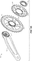
- FIG. 1A is an exploded view of a crank assembly 10, in accordance with an embodiment.
- crank assembly 10 is shown in conjunction with bicycle frame and bottom bracket portion 11 where it is mounted.
- Crank assembly 10 includes a left hand non-drive crank assembly 35 which includes a left hand crank arm 15b and a spindle 12 having a spindle interface 13.
- Crank assembly 10 also includes a right hand drive side crank assembly 36 which includes a drive side crank arm 15a, a fastener 100, a first chainring 105, and a second chainring 110.
- drive side crank arm 15a includes a chainring assembly interface 17 (having a number of splines 17n thereon) and a spindle interface 18.
- fastener 100 include, but are not limited to, a lock ring, a plurality of bolts arranged radially about the central axis of the crank (i.e. a bolt circle), and the like.
- crank assembly 10 includes one or more additional parts such as, but not limited to, pedals, a pedal washers, a preloader, dust caps, spindle spacers, bearings, hex nuts, preload adjusters, and the like. However, those parts are not shown for purposes of clarity.
- first chainring 105 has a first diameter and a plurality of teeth about an outer perimeter thereof. In one embodiment, first chainring 105 has 34 teeth. Although 34 teeth are described in one embodiment, the technology is well suited to the use of various other numbers of teeth such as 28, 30, 38, or the like. In one embodiment, first chainring 105 is comprised of a first material. In one embodiment, the first material is a metallic component, e.g., aluminum, titanium, steel, or the like.
- First chainring 105 includes a (first) center assembly shape 105a having an inner diameter.
- center assembly shape 105a differs depending upon the engagement method between first chainring 105 and chainring assembly interface 17.
- center assembly shape 105a is used to transfer the load (or torque) from crank assembly 10 to first chainring 105 and then on to the roller chain.
- second chainring 110 has a second diameter, different than the diameter of first chainring 105, and has a plurality of teeth about an outer perimeter thereof. In one embodiment, second chainring 110 has 24 teeth. Although 24 teeth are described in one embodiment, the technology is well suited to the use of various other numbers of teeth such as 20, 14, 10, or the like. In one embodiment, second chainring 110 is made from the same material as first chainring 105. In another embodiment, first chainring 105 and second chainring 110 are made from different materials.
- Second chainring 110 includes a (second) center assembly shape 110a having an inner diameter.
- center assembly shape 110a differs depending upon the engagement method between second chainring 110 and chainring assembly interface 17.
- center assembly shape 110a is used to transfer the load (or torque) from crank assembly 10 to second chainring 110 and then on to the roller chain.
- FIG. 1B a close up side view of drive side crank arm 15a with chainring assembly interface 17, splines 17n, and spindle interface 18 is shown in accordance with an embodiment.
- an axis A-A is shown.
- a circumference 44 and an axial length 34 of chainring assembly interface 17 are shown in orientation with the axis A-A.
- Chainring assembly 200 includes right hand drive side crank arm 15a, chainring assembly interface 17, a first chainring 205 having a (first) center assembly shape 205a, a second chainring 210 having a (second) center assembly shape 210a, and fastener 100.
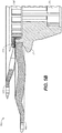
- a cross-section view 250 of the chainring assembly 200 of Figure 2A is shown in accordance with an embodiment.
- all splines 17n about chainring assembly interface 17 are engaged by first chainring 205 and second chainring 210.
- center assembly shape 205a of first chainring 205 uses a first portion of available axial length 34 of chainring assembly interface 17
- center assembly shape 210a of second chainring 210 uses a second portion of available axial length 34 such that both first chainring 205 and second chainring 210 make contact with splines 17n about the full circumference 44 of chainring assembly interface 17.
- the torque is distributed directly from crank assembly 10 to each of first chainring 205 and second chainring 210 separately.
- Chainring assembly 300 includes right hand drive side crank arm 15a, chainring assembly interface 17, a first chainring 305 having a center assembly shape 305a, a second chainring 310 having a center assembly shape 310a, and fastener 100.
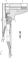
- a cross-section view 350 of the chainring assembly 300 of Figure 3A is shown in accordance with an embodiment.
- all splines 17n about chainring assembly interface 17 are engaged by first chainring 305.
- center assembly shape 305a of first chainring 305 uses the available axial length 34 of chainring assembly interface 17 around the entire circumference 44.
- center shape 305a of first chainring 305 has an outer diameter of splines 305b (e.g., a secondary chainring interface).
- splines 305b e.g., a secondary chainring interface
- the center assembly shape 310a of second chainring 310 makes contact with splines 305b instead of contacting the splines 17n of chainring assembly interface 17. In so doing, the torque is always transferred through the first chainring 305.
- the torque is transferred from crank assembly 10 to first chainring 305 and then into second chainring 310 through the secondary chainring interface, e.g., splines 305b of first chainring 305.
- Chainring assembly 400 includes right hand drive side crank arm 15a, chainring assembly interface 17, a first chainring 405 having a center assembly shape 405a, a second chainring 410 having a center assembly shape 410a, and fastener 100.
- a cross-section view 450 of the chainring assembly 400 of Figure 4A is shown in accordance with an embodiment.
- a first circumferential portion of circumference 44 of splines 17n of chainring assembly interface 17 are engaged by both first chainring 405 and second chainring 410 together and a remaining circumferential portion of circumference 44 of splines 17n of chainring assembly interface 17 are engaged only by first chainring 405.
- center assembly shape 405a of first chainring 405 has a number of depth features 405b sections therein. As such, some sections of center assembly shape 405a uses the entire axial length 34 of chainring assembly interface 17, while other sections of center assembly shape 405a only use a first portion of available axial length 34 of chainring assembly interface 17.
- Center assembly shape 410a of second chainring 410 has a number of arm type features that fit within the depth features 405b sections of center assembly shape 405a that use only the first portion of available axial length 34.
- the arm type features of center assembly shape 410a use a second portion of available axial length 34 such that center assembly shape 405a of first chainring 405 makes contact with splines 17n about the full circumference 44 of chainring assembly interface 17 while center assembly shape 410a of second chainring 410 makes contact 417 with only a portion of splines 17n about the circumference 44 of chainring assembly interface 17 at depth features 405b.
- the torque is proportionally distributed from crank assembly 10 to each of first chainring 405 and second chainring 410 proportional to the surface area of splines 17n engaged by each chainring.
- Chainring assembly 500 includes right hand drive side crank arm 15a, chainring assembly interface 17, a first chainring 505 having a center assembly shape 505a, a second chainring 510 having a center assembly shape 510a, and fastener 100.
- a cross-section view 550 of the chainring assembly 500 of Figure 5A is shown in accordance with an embodiment.
- a first circumferential portion of circumference 44 of splines 17n of chainring assembly interface 17 are engaged by a center assembly shape 505a of first chainring 505 and the remaining circumferential portion of circumference 44 of splines 17n of chainring assembly interface 17 are engaged by a center assembly shape 510a of second chainring 510.
- center assembly shape 505a of first chainring 505 has a number of arm type features that use the entire available axial length 34 across only a portion of circumference 44 of chainring assembly interface 17.
- center assembly shape 510a of second chainring 510 has a number of arm type features that use the entire available axial length 34 across only a portion of circumference 44 of chainring assembly interface 17.
- the arm type features of center assembly shape 510a of second chainring 510 are offset from the arm type features of center assembly shape 505a of first chainring 505.
- the arm type features of center assembly shape 505a mesh with the arm type features of center assembly shape 510a such that the combination of center assembly shape 505a and center assembly shape 510a results in complete contact 518 with splines 17n about the full circumference 44 and across the entire axial length 34 of chainring assembly interface 17.
- the torque is proportionally distributed from crank assembly 10 to each of first chainring 405 and second chainring 410 proportional to the surface area of splines 17n engaged by each chainring.
- Chainring assembly 600 includes right hand drive side crank arm 15a, chainring assembly interface 17, a first chainring 605 having a center assembly shape 605a, a second chainring 610 having a center assembly shape 610a, and fastener 100.
- a cross-section view 650 of the chainring assembly 600 of Figure 6A is shown in accordance with an embodiment.
- a first circumferential portion of circumference 44 of splines 17n of chainring assembly interface 17 are engaged by both first chainring 605 and second chainring 610 together and a remaining circumferential portion of circumference 44 of splines 17n of chainring assembly interface 17 are engaged only by first chainring 605.
- center assembly shape 605a of first chainring 605 has a number of depth features therein. As such, some sections of center assembly shape 605a uses the entire axial length 34 of chainring assembly interface 17, while other sections of center assembly shape 605a only use a first portion of available axial length 34 of chainring assembly interface 17.
- Center assembly shape 610a of second chainring 610 has a number of arm type features that fit within the depth features 605b sections of center assembly shape 605a that use only the first portion of available axial length 34 of chainring assembly interface 17.
- the arm type features of center assembly shape 610a fit within the depth features 605b sections and use the second portion of available axial length 34 of chainring assembly interface 17.
- the arm type features of center assembly shape 610a fit within the depth features 605b sections without engaging splines 17n of chainring assembly interface 17.
- second chainring 610 is fixed rotationally to first chainring 605 using assembly features (e.g. press, taper, or slip fit) to ensures radial and also rotational alignment between the two chainrings without the use of extra hardware.
- assembly features e.g. press, taper, or slip fit
- second chainring 610 is located radially by spline interface without any torque being transmitted from splines 17n to second chainring 610.
- all torque is transmitted from crank assembly 10 though first chainring 605 via splines 17n of chainring assembly interface 17.
- the torque is transmitted through crank assembly 10, into first chainring 605 and then into second chainring 610.
- embodiments described herein provide a chainring assembly that employs two separate chainrings held on to one spline using only one fastener.
- the chainring assembly can be built at a lower cost than is found in many conventional chainrings while still meeting or exceeding conventional chainring assembly strength and stiffness criteria.
- each of the chainrings can be individually or jointly replaced due to wear, different gearing ratios, personal preference, terrain being traversed, riding requirements, or the like.
- radial alignment between the two chainrings is maintained. Maintaining radial alignment between the two chainrings is important for shifting performance, e.g., when the roller chain is shifted between the two chainrings.
- the diameter of the chainrings can be larger or smaller and the diameter of the chainring is directly proportional to chainring flex.
- the chainrings normally have a smaller diameter (e.g., 2-5 inches) to keep the ground clearance at a maximum.
- the small diameter of the chainrings helps limit any chainring flex even when the chainrings are fixed in place with a single central fastener or a plurality of radial located fasteners at a central area thereof.
- one or both of the chainrings could be larger in diameter (e.g., 6-10 inches or more). If one or both of the chainrings are large in diameter, there could be some amount of chainring flex due to the chainrings being fixed in place with a single central fastener or a plurality of radial located fasteners at a central area thereof. As such, at least one connection of some type between the two chainrings at a location further from the central axis of the chainrings could be useful to reduce chainring flex.
- the at least one connection could be at least one removably coupleable connection between the two chainrings such as an adhesive, or it could be at least one fixedly coupleable connection between the two chainrings such as one or more rivets, welds, bolts, screws, or other fasteners.
Landscapes
- Engineering & Computer Science (AREA)
- Mechanical Engineering (AREA)
- Chemical & Material Sciences (AREA)
- Combustion & Propulsion (AREA)
- Transportation (AREA)
- General Engineering & Computer Science (AREA)
- Gears, Cams (AREA)
- Transmissions By Endless Flexible Members (AREA)
Description
- Embodiments of the invention generally relate to a chainring assembly for a chain driven vehicle.
- Traditional crank assemblies include one or more chainrings that are used to drive, via a chain, one or more sprockets coupled to an axle of a wheel. Chainrings are liable to bend, break or wear down based on use. Moreover, it is not uncommon to need a different size of chainring depending upon what type of terrain is being crossed or what maneuvers are being performed. As such, chainring manufacture, design and implementation are constantly being improved. However, as with almost all mechanical designs, a number of desirable features are incongruent. For example, going faster usually means a larger diameter chainring, while vehicle clearance calls for a smaller diameter chainring. As such, there is constant innovation and invention within the field of chainring assemblies, innovation and invention that requires more than simple substitution of parts in order to increase the desired performance while reducing the detrimental downside associated therewith
- The prior-art document
US 2010/317479 A1 discloses the preamble of claim 1. - According to some embodiments of the present invention there is provided a chainring assembly for a chain driven vehicle comprising:
- a drive side crank arm comprising a chainring assembly interface having a plurality of splines thereon,
- the chainring assembly interface having a circumference and an axial length;
- a first chainring having a first outer diameter and a first center assembly shape;
- a second chainring having a second outer diameter and a second center assembly shape, the second outer diameter being different than the first outer diameter; and
- a fastener to couple the first chainring and the second chainring with the chainring assembly interface, such that at least one of the first center assembly shape or the second center assembly shape engages with the plurality of splines, wherein that said first chainring and said second chainring are nested together so that there is no axial spacing between them at the chainring assembly interface
- In some aspects the chainring assembly further comprises:
- the first center assembly shape engages with the plurality of splines about the circumference of the chainring assembly interface over a first portion of the axial length; and
- the second center assembly shape engages with the plurality of splines about the circumference of the chainring assembly interface over a second portion of the axial length.
- In some aspects the chainring assembly further comprises:
the first center assembly shape comprising: - an inner diameter that engages with the plurality of splines about the circumference of the chainring assembly interface over an entirety of the axial length; and
- an outer diameter comprising a second plurality of splines about the circumference of the first center assembly shape,
- the second plurality of splines having a second axial length; and
- the second center assembly shape engages with the second plurality of splines about the circumference of the first center assembly shape over an entirety of the second axial length.
- In some aspects the chainring assembly further comprises:
- the first center assembly shape comprising:
- a circumferential portion that engages with the plurality of splines about the circumference of the chainring assembly interface; and
- a plurality of depth features formed within said circumferential portion,
- the circumferential portion not having the plurality of depth features covering the plurality of splines over an entire axial length, and
- the circumferential portion having the plurality of depth features covering a portion of said plurality of splines over only a first portion of the axial length; and
- the second center assembly shape comprising:
- a plurality of arm type features that align with the plurality of depth features of the first center assembly shape,
- the plurality of arm type features engage with the portion of the plurality of splines about the circumference of the chainring assembly interface via a second portion of the axial length.
- In some aspects the chainring assembly further comprises:
- the first center assembly shape comprising:
a first plurality of arm type features that engage with a first portion of the plurality of splines about the circumference of the chainring assembly interface over an entire axial length; and - the second center assembly shape comprising:
a second plurality of arm type features that engage with a second portion of the plurality of splines about the circumference of the chainring assembly interface over an entire axial length. - In some aspects the chainring assembly further comprises:
- the first center assembly shape comprising:
- a circumferential portion that engages with the plurality of splines about the circumference of the chainring assembly interface; and
- a plurality of depth features formed within said circumferential portion,
- the circumferential portion not having the plurality of depth features covering the plurality of splines over an entire axial length, and
- the circumferential portion having the plurality of depth features covering a portion of said plurality of splines over only a first portion of the axial length; and
- the second center assembly shape comprising:
- a plurality of arm type features that align with the plurality of depth features of the first center assembly shape,
- the plurality of arm type features engage with the first center assembly shape but do not engage any portion of the plurality of splines about the circumference of the chainring assembly interface.
- In some aspects the fastener is selected from the group consisting of: a single central fastener and a plurality of radially located fasteners.
- In some aspects the first chainring and the second chainring comprise a material selected from the group consisting of: aluminum, a titanium, and steel.
- In some aspects the first chainring is comprised of a first material and the second chainring is comprised of a second material different than the first material.
- According to another aspect of the invention there is provide a bicycle chainring assembly comprising:
- a drive side crank arm comprising a chainring assembly interface having a plurality of splines thereon,
- the chainring assembly interface having a circumference and an axial length;
- a first chainring having a first outer diameter and a first center assembly shape, the first outer diameter having a plurality of teeth thereon;
- a second chainring having a second outer diameter and a second center assembly shape,
- the second outer diameter having a plurality of teeth thereon,
- the second outer diameter being different than the first outer diameter; and
- a single fastener to couple the first chainring and the second chainring with the chainring assembly interface, such that at least one of the first center assembly shape or the second center assembly shape engages with the plurality of splines.
- In some aspects the bicycle chainring assembly further comprises:
- the first center assembly shape engages with the plurality of splines about the circumference of the chainring assembly interface over a first portion of the axial length; and
- the second center assembly shape engages with the plurality of splines about the circumference of the chainring assembly interface over a second portion of the axial length.
- In some aspects the bicycle chainring assembly further comprises:
- the first center assembly shape comprising:
- an inner diameter that engages with the plurality of splines about the circumference of the chainring assembly interface over an entirety of the axial length; and
- an outer diameter comprising a second plurality of splines about the circumference of the first center assembly shape,
- the second plurality of splines having a second axial length; and
- the second center assembly shape engages with the second plurality of splines about the circumference of the first center assembly shape over an entirety of the second axial length.
- In some aspects the bicycle chainring assembly further comprises:
- the first center assembly shape comprising:
- a circumferential portion that engages with the plurality of splines about the circumference of the chainring assembly interface; and
- a plurality of depth features formed within said circumferential portion,
- the circumferential portion not having the plurality of depth features covering the plurality of splines over an entire axial length, and
- the circumferential portion having the plurality of depth features covering a portion of said plurality of splines over only a first portion of the axial length; and
- the second center assembly shape comprising:
- a plurality of arm type features that align with the plurality of depth features of the first center assembly shape,
- the plurality of arm type features engage with the portion of the plurality of splines about the circumference of the chainring assembly interface via a second portion of the axial length.
- In some aspects the bicycle chainring assembly further comprises:
- the first center assembly shape comprising:
a first plurality of arm type features that engage with a first portion of the plurality of splines about the circumference of the chainring assembly interface over an entire axial length; and - the second center assembly shape comprising:
a second plurality of arm type features that engage with a second portion of the plurality of splines about the circumference of the chainring assembly interface over an entire axial length. - In some aspects the bicycle chainring assembly further comprises:
the first center assembly shape comprising: - a circumferential portion that engages with the plurality of splines about the circumference of the chainring assembly interface; and
- a plurality of depth features formed within said circumferential portion,
- the circumferential portion not having the plurality of depth features covering the plurality of splines over an entire axial length, and
- the circumferential portion having the plurality of depth features covering a portion of said plurality of splines over only a first portion of the axial length; and
- a plurality of arm type features that align with the plurality of depth features of the first center assembly shape,
- the plurality of arm type features engage with the first center assembly shape but do not engage any portion of the plurality of splines about the circumference of the chainring assembly interface.
- In some aspects the first chainring comprises a material selected from the group consisting of: aluminum, a titanium, and steel.
- In some aspects the second chainring comprises a material selected from the group consisting of: aluminum, a titanium, and steel.
- In some aspects the first chainring comprises a first material and the second chainring comprises a second material different than the first material.
- In some aspects the bicycle chainring assembly further comprises:
at least one removably coupleable connection between the first chainring and the second chainring at a location other than the location of the single fastener. - In some aspects the bicycle chainring assembly further comprises:
at least one fixedly coupleable connection between the first chainring and the second chainring at a location other than the location of the single fastener. - According to other embodiments of the present invention there is provided a crank arm and sprocket assembly comprising:
- a crank arm having a spline surface;
- a plurality sprockets coupled to said spline surface of said crank arm, said plurality of sprockets configured to receive a torque load from said crank arm via said spline surface of said crank arm;
- a fastener disposed to supply an axial load to said plurality of sprockets and retain said plurality of sprockets coupled to said spline surface of said crank arm.
- In some aspects said fastener does not transfer said torque load from said crank arm to any of said plurality of sprockets.
- In some aspects said fastener retains said plurality of sprockets coupled to said spline surface of said crank arm without requiring the use of additional hardware.
- In some aspects the crank arm and sprocket assembly further comprises:
a second fastener disposed to supply an axial load to said plurality of sprockets and retain said plurality of sprockets coupled to said spline surface of said crank arm. - In some embodiments said second fastener retains said plurality of sprockets coupled to said spline surface of said crank arm without requiring the use of additional hardware.
- According to some embodiments of the present invention there is provided a crank assembly for a chain-driven vehicle, such as a bicycle, comprising a chainring assembly as set out above.
- According to some embodiments of the present invention there is provided a chain-driven vehicle, such as a bicycle, comprising a chainring assembly as set out above.
- The present invention also envisages a chainring comprising the first or second chainring features set out in the statements above. It is envisaged that the first or second chainring could be made and sold separately as a spare part, e.g. for a bicycle, which already has the chainring assembly interface described herein. In some embodiments of the invention, the first and second chainrings could be sold together as a kit.
- Aspects of the present invention are illustrated by way of example, and not by way of limitation, in the accompanying drawings, wherein:
-
Figure 1A is an exploded view of a crank assembly, in accordance with an embodiment. -
Figure 1B is a side view of a crank arm with a spline, in accordance with an embodiment. -
Figure 2A is an exploded view of a chainring assembly having all splines engaged by each chainring, in accordance with an embodiment. -
Figure 2B is a cross-section view of the chainring assembly ofFigure 2A , in accordance with an embodiment. -
Figure 3A is an exploded view of a chainring assembly having all splines engaged by a first chainring, in accordance with an embodiment. -
Figure 3B is a cross-section view of the chainring assembly ofFigure 3A , in accordance with an embodiment. -
Figure 4A is an exploded view of a chainring assembly having a first circumferential portion of splines engaged by each chainring together with a remaining circumferential portion engaged only by one chainring, in accordance with an embodiment. -
Figure 4B is a cross-section view of the chainring assembly ofFigure 4A , in accordance with an embodiment. -
Figure 5A is an exploded view of a chainring assembly having a first circumferential portion of splines engaged by a first chainring and a remaining circumferential portion engaged by a second chainring, in accordance with an embodiment. -
Figure 5B is a cross-section view of the chainring assembly ofFigure 5A , in accordance with an embodiment. -
Figure 6A is an exploded view of a chainring assembly having an entire circumferential portion of splines engaged by a first chainring and a remaining axial space filled by a second chainring without the second chainring engaging any portion of the splines, in accordance with an embodiment. -
Figure 6B is a cross-section view of the chainring assembly ofFigure 6A , in accordance with an embodiment. - The drawings referred to in this description should be understood as not being drawn to scale except if specifically noted.
- The detailed description set forth below in connection with the appended drawings is intended as a description of various embodiments of the present invention and is not intended to represent the only embodiments in which the present invention is to be practiced. Each embodiment described in this disclosure is provided merely as an example or illustration of the present invention, and should not necessarily be construed as preferred or advantageous over other embodiments. In some instances, well known methods, procedures, and objects have not been described in detail as not to unnecessarily obscure aspects of the present disclosure.
- For purposes of the following discussion, the term "chainring" (or chainwheel) refers to one or more toothed components that are located at the crank assembly of a vehicle (e.g., where the cranks and pedals are located). The chainring rotates in either a clockwise or counterclockwise direction based on input from the rider provided via a pedal (or crank).
- The term "sprocket" refers to the one or more toothed components that are found at the drive wheel of a vehicle (usually the rear wheel). The rotation of the one or more sprockets (in the appropriate direction) causes the drive wheel of the vehicle to rotate.
- The term "roller chain" refers to the chain on a vehicle, such as a bicycle, that fits into the teeth of the chainring and the teeth of the sprocket to form a mechanical connection between the two. Thus, as the chainring is rotated, usually by peddling or the like, movement of the roller chain occurs. The movement of the roller chain about the chainring and the sprocket causes a movement of the sprocket at the drive wheel of the bicycle.
- The amount of rotational movement of the sprocket depends upon the size ratio between the chainring and the sprocket. For example, if the ratio is 1:1, (e.g., the chainring and sprocket are the same tooth count) a rotation of the chainring will cause the roller chain to rotate the sprocket the same amount. However, if the ratio is 2:1, (e.g., the chainring has twice the tooth count of the sprocket) a rotation of the chainring will cause the roller chain to rotate the sprocket twice as much. For example, a full revolution of the chainring will result in two full rotations of the sprocket.
- In one embodiment of the chainring assembly described herein create a chainring assembly that employs two separate chainrings held on to one spline using only one fastener. In so doing, the chainring assembly can be built at a lower cost than is found in many conventional chainring assemblies while still meeting or exceeding conventional chainring assembly strength and stiffness criteria. Moreover, each of the chainrings can be individually or jointly replaced due to wear, different gearing ratios, personal preference, terrain being traversed, riding requirements, or the like.
- By allowing either chainring to take part of the torque from the other chainring utilizing the spline on the chainring assembly interface, a more robust chainring assembly interface is provided. Moreover, due to the stacking or nesting of the two chainrings, the amount of central movement between the two chainrings is limited and, as such, a robust and stronger way of transferring the torque from the crank onto either chainring and then on to the roller chain is provided.
- Further, deviation in a radial alignment of the two chainrings is detrimental to shifting performance. However, in one embodiment, due to the stacking or nesting of the two chainrings, the radial alignment between the two chainrings is maintained. Maintaining radial alignment between the two chainrings is important for shifting performance, e.g., when the roller chain is shifted between the two chainrings.
-
Figure 1A is an exploded view of acrank assembly 10, in accordance with an embodiment. In one embodiment, crankassembly 10 is shown in conjunction with bicycle frame andbottom bracket portion 11 where it is mounted.Crank assembly 10 includes a left hand non-drive crankassembly 35 which includes a left hand crankarm 15b and aspindle 12 having aspindle interface 13.Crank assembly 10 also includes a right hand drive side crankassembly 36 which includes a drive side crankarm 15a, afastener 100, afirst chainring 105, and asecond chainring 110. In one embodiment, drive side crankarm 15a includes a chainring assembly interface 17 (having a number ofsplines 17n thereon) and aspindle interface 18. Examples offastener 100 include, but are not limited to, a lock ring, a plurality of bolts arranged radially about the central axis of the crank (i.e. a bolt circle), and the like. - During assembly,
fastener 100 will fixedly couplefirst chainring 105 andsecond chainring 110 withchainring assembly interface 17 of right hand drive side crankarm 15a thereby forming the right hand drive side crankassembly 36.Spindle 12 is inserted through bicycle framebottom bracket portion 11 andspindle interface 13 couples withspindle interface 18 on right hand drive side crankassembly 36. In one embodiment, crankassembly 10 includes one or more additional parts such as, but not limited to, pedals, a pedal washers, a preloader, dust caps, spindle spacers, bearings, hex nuts, preload adjusters, and the like. However, those parts are not shown for purposes of clarity. - In one embodiment,
first chainring 105 has a first diameter and a plurality of teeth about an outer perimeter thereof. In one embodiment,first chainring 105 has 34 teeth. Although 34 teeth are described in one embodiment, the technology is well suited to the use of various other numbers of teeth such as 28, 30, 38, or the like. In one embodiment,first chainring 105 is comprised of a first material. In one embodiment, the first material is a metallic component, e.g., aluminum, titanium, steel, or the like. -
First chainring 105 includes a (first)center assembly shape 105a having an inner diameter. In one embodiment,center assembly shape 105a differs depending upon the engagement method betweenfirst chainring 105 andchainring assembly interface 17. In one embodiment,center assembly shape 105a is used to transfer the load (or torque) from crankassembly 10 tofirst chainring 105 and then on to the roller chain. - In one embodiment,
second chainring 110 has a second diameter, different than the diameter offirst chainring 105, and has a plurality of teeth about an outer perimeter thereof. In one embodiment,second chainring 110 has 24 teeth. Although 24 teeth are described in one embodiment, the technology is well suited to the use of various other numbers of teeth such as 20, 14, 10, or the like. In one embodiment,second chainring 110 is made from the same material asfirst chainring 105. In another embodiment,first chainring 105 andsecond chainring 110 are made from different materials. -
Second chainring 110 includes a (second)center assembly shape 110a having an inner diameter. In one embodiment,center assembly shape 110a differs depending upon the engagement method betweensecond chainring 110 andchainring assembly interface 17. In one embodiment,center assembly shape 110a is used to transfer the load (or torque) from crankassembly 10 tosecond chainring 110 and then on to the roller chain. - Referring now to
Figure 1B , a close up side view of drive side crankarm 15a withchainring assembly interface 17,splines 17n, andspindle interface 18 is shown in accordance with an embodiment. InFigure 1B , an axis A-A is shown. In addition, acircumference 44 and anaxial length 34 ofchainring assembly interface 17 are shown in orientation with the axis A-A. - With reference now to
Figure 2A , an exploded view of achainring assembly 200 having all splines engaged by each chainring is shown in accordance with an embodiment.Chainring assembly 200 includes right hand drive side crankarm 15a,chainring assembly interface 17, afirst chainring 205 having a (first)center assembly shape 205a, asecond chainring 210 having a (second)center assembly shape 210a, andfastener 100. - Referring also to
Figure 2B , across-section view 250 of thechainring assembly 200 ofFigure 2A is shown in accordance with an embodiment. Inchainring assembly 200, allsplines 17n aboutchainring assembly interface 17 are engaged byfirst chainring 205 andsecond chainring 210. For example, inchainring assembly 200center assembly shape 205a offirst chainring 205 uses a first portion of availableaxial length 34 ofchainring assembly interface 17 andcenter assembly shape 210a ofsecond chainring 210 uses a second portion of availableaxial length 34 such that bothfirst chainring 205 andsecond chainring 210 make contact withsplines 17n about thefull circumference 44 ofchainring assembly interface 17. In so doing, the torque is distributed directly from crankassembly 10 to each offirst chainring 205 andsecond chainring 210 separately. - With reference now to
Figure 3A , an exploded view of achainring assembly 300 having allsplines 17n engaged byfirst chainring 305 is shown in accordance with an embodiment.Chainring assembly 300 includes right hand drive side crankarm 15a,chainring assembly interface 17, afirst chainring 305 having acenter assembly shape 305a, asecond chainring 310 having acenter assembly shape 310a, andfastener 100. - Referring also to
Figure 3B , across-section view 350 of thechainring assembly 300 ofFigure 3A is shown in accordance with an embodiment. Inchainring assembly 300, allsplines 17n aboutchainring assembly interface 17 are engaged byfirst chainring 305. For example, inchainring assembly 300center assembly shape 305a offirst chainring 305 uses the availableaxial length 34 ofchainring assembly interface 17 around theentire circumference 44. - Moreover,
center shape 305a offirst chainring 305 has an outer diameter ofsplines 305b (e.g., a secondary chainring interface). As such, when asecond chainring 310 is utilized, thecenter assembly shape 310a ofsecond chainring 310 makes contact withsplines 305b instead of contacting thesplines 17n ofchainring assembly interface 17. In so doing, the torque is always transferred through thefirst chainring 305. Thus, when thesecond chainring 310 is utilized, the torque is transferred from crankassembly 10 tofirst chainring 305 and then intosecond chainring 310 through the secondary chainring interface, e.g., splines 305b offirst chainring 305. - With reference now to
Figure 4A , an exploded view of achainring assembly 400 having a first circumferential portion ofcircumference 44 ofsplines 17n engaged by bothfirst chainring 405 andsecond chainring 410 together and a remaining circumferential portion ofcircumference 44 ofsplines 17n engaged only byfirst chainring 405 is shown in accordance with an embodiment.Chainring assembly 400 includes right hand drive side crankarm 15a,chainring assembly interface 17, afirst chainring 405 having acenter assembly shape 405a, asecond chainring 410 having acenter assembly shape 410a, andfastener 100. - Referring also to
Figure 4B , across-section view 450 of thechainring assembly 400 ofFigure 4A is shown in accordance with an embodiment. Inchainring assembly 400, a first circumferential portion ofcircumference 44 ofsplines 17n ofchainring assembly interface 17 are engaged by bothfirst chainring 405 andsecond chainring 410 together and a remaining circumferential portion ofcircumference 44 ofsplines 17n ofchainring assembly interface 17 are engaged only byfirst chainring 405. For example, inchainring assembly 400center assembly shape 405a offirst chainring 405 has a number of depth features 405b sections therein. As such, some sections ofcenter assembly shape 405a uses the entireaxial length 34 ofchainring assembly interface 17, while other sections ofcenter assembly shape 405a only use a first portion of availableaxial length 34 ofchainring assembly interface 17. -
Center assembly shape 410a ofsecond chainring 410 has a number of arm type features that fit within the depth features 405b sections ofcenter assembly shape 405a that use only the first portion of availableaxial length 34. As such, the arm type features ofcenter assembly shape 410a use a second portion of availableaxial length 34 such thatcenter assembly shape 405a offirst chainring 405 makes contact withsplines 17n about thefull circumference 44 ofchainring assembly interface 17 whilecenter assembly shape 410a ofsecond chainring 410 makescontact 417 with only a portion ofsplines 17n about thecircumference 44 ofchainring assembly interface 17 at depth features 405b. In so doing, the torque is proportionally distributed from crankassembly 10 to each offirst chainring 405 andsecond chainring 410 proportional to the surface area ofsplines 17n engaged by each chainring. - With reference now to
Figure 5A , an exploded view of achainring assembly 500 having a first circumferential portion ofcircumference 44 ofsplines 17n ofchainring assembly interface 17 engaged by afirst chainring 505 and a remaining circumferential portion ofcircumference 44 ofsplines 17n ofchainring assembly interface 17 engaged by asecond chainring 510 is shown in accordance with an embodiment.Chainring assembly 500 includes right hand drive side crankarm 15a,chainring assembly interface 17, afirst chainring 505 having acenter assembly shape 505a, asecond chainring 510 having acenter assembly shape 510a, andfastener 100. - Referring also to
Figure 5B , across-section view 550 of thechainring assembly 500 ofFigure 5A is shown in accordance with an embodiment. Inchainring assembly 500, a first circumferential portion ofcircumference 44 ofsplines 17n ofchainring assembly interface 17 are engaged by acenter assembly shape 505a offirst chainring 505 and the remaining circumferential portion ofcircumference 44 ofsplines 17n ofchainring assembly interface 17 are engaged by acenter assembly shape 510a ofsecond chainring 510. For example, inchainring assembly 500center assembly shape 505a offirst chainring 505 has a number of arm type features that use the entire availableaxial length 34 across only a portion ofcircumference 44 ofchainring assembly interface 17. - Similarly,
center assembly shape 510a ofsecond chainring 510 has a number of arm type features that use the entire availableaxial length 34 across only a portion ofcircumference 44 ofchainring assembly interface 17. However, the arm type features ofcenter assembly shape 510a ofsecond chainring 510 are offset from the arm type features ofcenter assembly shape 505a offirst chainring 505. As such, the arm type features ofcenter assembly shape 505a mesh with the arm type features ofcenter assembly shape 510a such that the combination ofcenter assembly shape 505a andcenter assembly shape 510a results incomplete contact 518 withsplines 17n about thefull circumference 44 and across the entireaxial length 34 ofchainring assembly interface 17. In so doing, the torque is proportionally distributed from crankassembly 10 to each offirst chainring 405 andsecond chainring 410 proportional to the surface area ofsplines 17n engaged by each chainring. - With reference now to
Figure 6A , an exploded view of achainring assembly 600 having an entire circumferential portion ofcircumference 44 ofsplines 17n ofchainring assembly interface 17 engaged by a first chainring and a remaining axial space ofaxial length 34 ofchainring assembly interface 17 filled by asecond chainring 610 without thesecond chainring 610 engaging any portion of thesplines 17n is shown in accordance with an embodiment.Chainring assembly 600 includes right hand drive side crankarm 15a,chainring assembly interface 17, afirst chainring 605 having acenter assembly shape 605a, asecond chainring 610 having acenter assembly shape 610a, andfastener 100. - Referring also to
Figure 6B , across-section view 650 of thechainring assembly 600 ofFigure 6A is shown in accordance with an embodiment. Inchainring assembly 600, a first circumferential portion ofcircumference 44 ofsplines 17n ofchainring assembly interface 17 are engaged by bothfirst chainring 605 andsecond chainring 610 together and a remaining circumferential portion ofcircumference 44 ofsplines 17n ofchainring assembly interface 17 are engaged only byfirst chainring 605. For example, inchainring assembly 600center assembly shape 605a offirst chainring 605 has a number of depth features therein. As such, some sections ofcenter assembly shape 605a uses the entireaxial length 34 ofchainring assembly interface 17, while other sections ofcenter assembly shape 605a only use a first portion of availableaxial length 34 ofchainring assembly interface 17. -
Center assembly shape 610a ofsecond chainring 610 has a number of arm type features that fit within the depth features 605b sections ofcenter assembly shape 605a that use only the first portion of availableaxial length 34 ofchainring assembly interface 17. In one embodiment, the arm type features ofcenter assembly shape 610a fit within the depth features 605b sections and use the second portion of availableaxial length 34 ofchainring assembly interface 17. Moreover, the arm type features ofcenter assembly shape 610a fit within the depth features 605b sections without engagingsplines 17n ofchainring assembly interface 17. - In other words,
second chainring 610 is fixed rotationally tofirst chainring 605 using assembly features (e.g. press, taper, or slip fit) to ensures radial and also rotational alignment between the two chainrings without the use of extra hardware. As such,second chainring 610 is located radially by spline interface without any torque being transmitted fromsplines 17n tosecond chainring 610. Instead, because of 605b, all torque is transmitted from crankassembly 10 thoughfirst chainring 605 viasplines 17n ofchainring assembly interface 17. As such, whensecond chainring 610 is in use, the torque is transmitted through crankassembly 10, intofirst chainring 605 and then intosecond chainring 610. - Thus, embodiments described herein provide a chainring assembly that employs two separate chainrings held on to one spline using only one fastener. In so doing, the chainring assembly can be built at a lower cost than is found in many conventional chainrings while still meeting or exceeding conventional chainring assembly strength and stiffness criteria. Moreover, each of the chainrings can be individually or jointly replaced due to wear, different gearing ratios, personal preference, terrain being traversed, riding requirements, or the like.
- By allowing either chainring to take part of the torque from the other chainring utilizing the axial length and/or circumference of the spline of the chainring assembly interface, a more robust chainring assembly interface is provided. Moreover, due to the stacking or nesting of the two chainrings, the amount of central movement between the two chainrings is limited and, as such, a robust and stronger way of transferring the torque from the crank onto either chainring and then on to the roller chain is provided.
- Further, deviation in a radial alignment of the two chainrings is detrimental to shifting performance. Thus, in one embodiment, due to the stacking or nesting of the two chainrings, the radial alignment between the two chainrings is maintained. Maintaining radial alignment between the two chainrings is important for shifting performance, e.g., when the roller chain is shifted between the two chainrings.
- In one embodiment, depending upon the type of bicycle being used the diameter of the chainrings can be larger or smaller and the diameter of the chainring is directly proportional to chainring flex. For example, in a mountain bike, trick bike, BMX bike, or the like, the chainrings normally have a smaller diameter (e.g., 2-5 inches) to keep the ground clearance at a maximum. The small diameter of the chainrings helps limit any chainring flex even when the chainrings are fixed in place with a single central fastener or a plurality of radial located fasteners at a central area thereof.
- However, in the case of a road bike or other type of bicycle that is used in an environment where ground clearance is not as big of a concern as top speed, it is possible that one or both of the chainrings could be larger in diameter (e.g., 6-10 inches or more). If one or both of the chainrings are large in diameter, there could be some amount of chainring flex due to the chainrings being fixed in place with a single central fastener or a plurality of radial located fasteners at a central area thereof. As such, at least one connection of some type between the two chainrings at a location further from the central axis of the chainrings could be useful to reduce chainring flex. The at least one connection could be at least one removably coupleable connection between the two chainrings such as an adhesive, or it could be at least one fixedly coupleable connection between the two chainrings such as one or more rivets, welds, bolts, screws, or other fasteners.
- The foregoing Description of Embodiments is not intended to be exhaustive or to limit the embodiments to the precise form described. Instead, example embodiments in this Description of Embodiments have been presented in order to enable persons of skill in the art to make and use embodiments of the described subject matter. Moreover, various embodiments have been described in various combinations. However, any two or more embodiments could be combined. Although some embodiments have been described in a language specific to structural features and/or methodological acts, it is to be understood that the subject matter defined in the appended claims is not necessarily limited to the specific features or acts described above. Rather, the specific features and acts described above are disclosed by way of illustration and as example forms of implementing the claims and their equivalents.
Claims (12)
- A chainring assembly (200, 300, 400, 500, 600) for a chain driven vehicle comprising:a drive side crank arm (15a) comprising a chainring assembly interface (17) having a plurality of splines (17n) thereon, the chainring assembly interface (17) having a circumference and an axial length (34);a first chainring (105, 205, 305, 405, 505, 605) having a first outer diameter and a first center assembly shape (105a, 205a, 305a, 405a, 505a, 605a);a second chainring (110, 210, 310, 410, 510, 610) having a second outer diameter and a second center assembly shape (110a, 210a, 310a, 410a, 510a, 610a), the second outer diameter being different than the first outer diameter; anda fastener (100) to couple the first chainring (105, 205, 305, 405, 505, 605) and the second chainring (110, 210, 310, 410, 510, 610) with the chainring assembly interface (17), such that at least one of the first center assembly shape (105a, 205a, 305a, 405a, 505a, 605a) or the second center assembly shape (110a, 210a, 310a, 410a, 510a, 610a) engages with the plurality of splines (17n) ;characterized in that said first chainring (105, 205, 305, 405, 505, 605) and said second chainring (110, 210, 310, 410, 510, 610) are nested together so that there is no axial spacing between them at the chainring assembly interface (17).
- The chainring assembly (200, 300, 400, 500, 600) of Claim 1, further comprising:the first center assembly shape (105a, 205a, 305a, 405a, 505a, 605a) engages with the plurality of splines (17n) about the circumference of the chainring assembly interface (17) over a first portion of the axial length (34); andthe second center assembly shape (110a, 210a, 310a, 410a, 510a, 610a) engages with the plurality of splines (17n) about the circumference of the chainring assembly interface (17) over a second portion of the axial length (34).
- The chainring assembly (200, 300, 400, 500, 600) of Claim 1, further comprising:the first center assembly shape (105a, 205a, 305a, 405a, 505a, 605a) comprising:an inner diameter that engages with the plurality of splines (17n) about the circumference (44) of the chainring assembly interface (17) over an entirety of the axial length (34); andan outer diameter comprising a second plurality of splines (305b) about the circumference of the first center assembly shape (105a, 205a, 305a, 405a, 505a, 605a),the second plurality of splines (305b) having a second axial length; andthe second center assembly shape (110a, 210a, 310a, 410a, 510a, 610a) engages with the second plurality of splines (305b) about the circumference of the first center assembly shape (105a, 205a, 305a, 405a, 505a, 605a) over an entirety of the second axial length.
- The chainring assembly (200, 300, 400, 500, 600) of Claim 1, further comprising:the first center assembly shape (105a, 205a, 305a, 405a, 505a, 605a) comprising:a circumferential portion that engages with the plurality of splines (17n) about the circumference (44) of the chainring assembly interface (17) ; anda plurality of depth features (405b, 605b) formed within said circumferential portion, the circumferential portion not having the plurality of depth feature; (405b)covering the plurality of splines (17n) over an entire axial length (34), and the circumferential portion having the plurality of depth feature; (405b)covering a portion of said plurality of splines (17n) over only a first portion of the axial length (34) ; andthe second center assembly shape (110a, 210a, 310a, 410a, 510a, 610a) comprising:a plurality of arm type features that align with the plurality of depth features (405b, 605b) of the first center assembly shape (105a, 205a, 305a, 405a, 505a, 605a),the plurality of arm type features engage with the portion of the plurality of splines (17n) about the circumference (44) of the chainring assembly interface (17) via a second portion of the axial length (34)
- The chainring assembly (200, 300, 400, 500, 600) of Claim 1, further comprising:the first center assembly shape (105a, 205a, 305a, 405a, 505a, 605a) comprising:
a first plurality of arm type features that engage with a first portion of the plurality of splines (17n) about the circumference (44) of the chainring assembly interface (17) over an entire axial length (34) ; andthe second center assembly shape (110a, 210a, 310a, 410a, 510a, 610a) comprising:
a second plurality of arm type features that engage with a second portion of the plurality of splines (17) about the circumference (44) of the chainring assembly interface (17) over an entire axial length (34). - The chainring assembly (200, 300, 400, 500, 600) of Claim 1, further comprising:the first center assembly shape (105a, 205a, 305a, 405a, 505a, 605a) comprising:a circumferential portion that engages with the plurality of splines (17n) about the circumference (44) of the chainring assembly interface (17) ; anda plurality of depth features (405b, 605b) formed within said circumferential portion, the circumferential portion not having the plurality of depth features (405b, 605b)covering the plurality of splines (17n) over an entire axial lenght (34), and the circumferential portion having the plurality of depth feature; (405b, 605b)covering a portion of said plurality of splines (17n) over only a first portion of the axial lenght (34); andthe second center assembly shape (110a, 210a, 310a, 410a, 510a, 610a) comprising:a plurality of arm type features that align with the plurality of depth features (405b, 605b) of the first center assembly shape (105a, 205a, 305a, 405a, 505a, 605a),the plurality of arm type features engage with the first center assembly shape (105a, 205a, 305a, 405a, 505a, 605a) but do not engage any portion of the plurality of splines (17n) about the circumference (44) of the chainring assembly interface (17).
- The chainring assembly (200, 300, 400, 500, 600) of any preceding Claim, wherein the fastener (100) is selected from the group consisting of: a single central fastener and a plurality of radially located fasteners.
- The chainring assembly (200, 300, 400, 500, 600) of any preceding Claim, wherein the first chainring (105, 205, 305, 405, 505, 605) and the second chainring (110, 210, 310, 410, 510, 610) comprise a material selected from the group consisting of: aluminum, a titanium, and steel.
- The chainring assembly (200, 300, 400, 500, 600) of any of Claims 1 to 7, wherein the first chainring (105, 205, 305, 405, 505, 605) comprises a first material and the second chainring (110, 210, 310, 410, 510, 610) comprises a second material different than the first material.
- The chainring assembly (200, 300, 400, 500, 600) of any preceding Claim, wherein said first chainring (105, 205, 305, 405, 505, 605) comprises a plurality of teeth around said first outer diameter, said second chainring (110, 210, 310,410, 510, 610) comprises a plurality of teeth around said second outer diameter, and said fastener (100) comprises a single fastener, whereby said chainring assembly (200, 300, 400, 500, 600) is suitable for a bicycle.
- A crank assembly (10) for chain-driven vehicle, such as a bicycle, which crank assembly (10) comprises a chainring assembly (200, 300, 400, 500, 600) as claimed in any preceding Claim.
- A chain-driven vehicle, such as a bicycle, comprising a chainring assembly (200, 300, 400, 500, 600) as claimed in any of Claims 1 to 10.
Applications Claiming Priority (2)
| Application Number | Priority Date | Filing Date | Title |
|---|---|---|---|
| US201762491958P | 2017-04-28 | 2017-04-28 | |
| US15/953,903 US11014628B2 (en) | 2017-04-28 | 2018-04-16 | Cinch direct mount 2X ring system |
Publications (2)
| Publication Number | Publication Date |
|---|---|
| EP3401203A1 EP3401203A1 (en) | 2018-11-14 |
| EP3401203B1 true EP3401203B1 (en) | 2021-03-24 |
Family
ID=62091776
Family Applications (1)
| Application Number | Title | Priority Date | Filing Date |
|---|---|---|---|
| EP18170147.5A Not-in-force EP3401203B1 (en) | 2017-04-28 | 2018-04-30 | Chainring assembly |
Country Status (2)
| Country | Link |
|---|---|
| US (4) | US11014628B2 (en) |
| EP (1) | EP3401203B1 (en) |
Families Citing this family (12)
| Publication number | Priority date | Publication date | Assignee | Title |
|---|---|---|---|---|
| US8820192B2 (en) | 2009-04-29 | 2014-09-02 | Race Face Prerformance Products Inc. | Bicycle crank arm and insert therefore |
| US10343745B2 (en) * | 2013-09-26 | 2019-07-09 | Sram, Llc | Bicycle crank arm and chainring carrier assembly |
| CN112517887A (en) | 2016-04-11 | 2021-03-19 | 福克斯制造有限公司 | Method for forming a bicycle front sprocket assembly |
| US11014628B2 (en) | 2017-04-28 | 2021-05-25 | Fox Factory, Inc. | Cinch direct mount 2X ring system |
| US10889353B2 (en) * | 2018-01-24 | 2021-01-12 | Shimano Inc. | Bicycle rear sprocket assembly |
| USD847034S1 (en) * | 2018-03-09 | 2019-04-30 | Sram Llc | Chainring for a bicycle |
| US12227262B2 (en) | 2018-12-07 | 2025-02-18 | Fox Factory, Inc. | Mid-sprocket assembly |
| US11359709B2 (en) | 2018-12-18 | 2022-06-14 | Fox Factory, Inc. | Chainring |
| US11680633B2 (en) | 2019-02-08 | 2023-06-20 | Fox Factory, Inc. | Chainring |
| DE102020201889A1 (en) * | 2020-02-14 | 2021-08-19 | Sram Deutschland Gmbh | Pinion for a bicycle drive |
| USD938864S1 (en) * | 2021-04-01 | 2021-12-21 | Yuantao Tong | Bracket for bicycle |
| DE102023115800B3 (en) * | 2023-06-16 | 2024-06-27 | Miranda & Irmão Lda. | DRIVE SYSTEM WITH ONE DRIVE SHAFT AND ONE CHAINRING |
Family Cites Families (231)
| Publication number | Priority date | Publication date | Assignee | Title |
|---|---|---|---|---|
| FR904975A (en) | 1944-06-10 | 1945-11-21 | Advanced fixing device for cycle cranksets | |
| US2451690A (en) * | 1945-05-12 | 1948-10-19 | Deere & Co | Two-part sprocket |
| US2468011A (en) | 1946-07-27 | 1949-04-19 | Fisette Hazel | Pedally driven exercising and amusement apparatus |
| FR946276A (en) | 1946-09-30 | 1949-05-30 | Dayton Cycle Company Ltd | Improvements to the assembly of the bottom bracket axle and the connecting rods of a cycle |
| US2793571A (en) | 1949-11-15 | 1957-05-28 | Us Rubber Co | Suction press roll |
| US3200665A (en) | 1963-02-14 | 1965-08-17 | Wells Martin | Gears |
| US3168836A (en) | 1963-03-05 | 1965-02-09 | Frank A Militana | Sprocket with a replaceable wear rim for a crawler type vehicle |
| US3304796A (en) | 1964-08-27 | 1967-02-21 | Rex Chainbelt Inc | Plastic hub and insert assembly for wheels and sprockets |
| US3272027A (en) | 1964-11-18 | 1966-09-13 | Link Belt Co | Integral gear and drive eccentric unit |
| US3371549A (en) | 1966-09-08 | 1968-03-05 | Pitney Bowes Inc | Resilient rotary driving elements and system thereof |
| US3815439A (en) | 1972-10-20 | 1974-06-11 | Shimano Industrial Co | Multi-speed transmission front gear system |
| FR2219709A5 (en) * | 1973-02-23 | 1974-09-20 | Peyrard Marcel | |
| US3987539A (en) | 1974-01-31 | 1976-10-26 | Consolidated Foods Corporation | Method of making a molded commutator |
| US3903754A (en) | 1974-06-07 | 1975-09-09 | Pino International Ltd | Bicycle crank hub assembly |
| US4144773A (en) | 1976-07-12 | 1979-03-20 | Addicks Lyle F | Bicycle sprocket wheel |
| USRE30758E (en) | 1976-09-03 | 1981-10-06 | Pedal-actuated bicycle gear shift means | |
| JPS53165964U (en) | 1977-06-02 | 1978-12-26 | ||
| JPS563264Y2 (en) | 1977-08-19 | 1981-01-24 | ||
| DE2861860D1 (en) * | 1977-12-28 | 1982-07-08 | Shimano Industrial Co | Chain wheel and crank assembly for a cycle |
| US4174642A (en) | 1978-02-09 | 1979-11-20 | Gehl Company | Chain drive including sprocket having alternate wide and narrow teeth |
| JPS54183860U (en) * | 1978-06-16 | 1979-12-26 | ||
| US4240303A (en) | 1978-09-27 | 1980-12-23 | Mosley Earnest D | Chain sprocket with opposite frangible side guide plates |
| US4331043A (en) * | 1979-05-10 | 1982-05-25 | Shimano Industrial Company, Limited | Gear crank for a bicycle |
| FR2459920A1 (en) | 1979-06-26 | 1981-01-16 | Simplex Ets | CHAIN ROLLING WHEEL, IN PARTICULAR FOR SPEED CHANGES OF BICYCLES AND LIKE VEHICLES |
| JPS6010955Y2 (en) * | 1980-02-13 | 1985-04-12 | 株式会社シマノ | gear crank device |
| US4358967A (en) | 1980-06-23 | 1982-11-16 | Kastan B Linn | Foot operated crank assembly |
| FR2487772B1 (en) | 1980-08-04 | 1987-01-09 | Haubtmann A Sa Ets | MONOBLOCK ASSEMBLY COMPRISING AT LEAST ONE TRAY WITH OR WITHOUT CHAIN PROTECTOR FOR CRIMPING ON HANDLES, USEFUL FOR BICYCLES AND SIMILAR VEHICLES, AND MANUFACTURING METHOD THEREOF |
| DE3173124D1 (en) | 1980-08-18 | 1986-01-16 | Shimano Industrial Co | Gear crank for pedal vehicle |
| FR2501615B1 (en) | 1981-03-10 | 1986-04-11 | Shimano Industrial Co | ORGAN BRAKE BICYCLE CRANKSET FIXING SCREW |
| JPS6027116Y2 (en) | 1981-03-30 | 1985-08-15 | 株式会社杉野鉄工所 | plastic gear for bicycle |
| JPS57188592U (en) | 1981-05-27 | 1982-11-30 | ||
| JPS5846691U (en) | 1981-09-24 | 1983-03-29 | 株式会社シマノ | bicycle crank |
| US4583422A (en) | 1982-09-20 | 1986-04-22 | Winnett Boyd | Pedal crank and chain wheel assembly for bicycles |
| JPS6015074U (en) * | 1983-07-11 | 1985-02-01 | 株式会社シマノ | bicycle gear crank |
| US4545691A (en) | 1983-07-18 | 1985-10-08 | B. Linn Kastan | Bicycle crank bearing assembly |
| CH661903A5 (en) | 1983-12-12 | 1987-08-31 | Jiri Krampera | BICYCLE CHAIN GEAR. |
| JPS60149484U (en) | 1984-03-15 | 1985-10-04 | 株式会社シマノ | Multi-stage front chain gear for bicycles |
| DE3531030A1 (en) | 1984-05-18 | 1987-03-05 | Thun Alfred Heinrich | Bottom bracket ball bearing for bicycles |
| US4722722A (en) | 1986-06-27 | 1988-02-02 | Jepmar Research | Rotatable drive member formed from injection molded plastics material with preform insert |
| US4867733A (en) | 1987-01-23 | 1989-09-19 | Honda Giken Kogyo Kabushiki Kaisha | Chain drive system |
| US5226469A (en) | 1987-07-01 | 1993-07-13 | Kawasaki Jukogyo Kabushiki Kaisha | Composite structures and methods of manufacturing the same |
| DE313345T1 (en) | 1987-10-21 | 1990-05-03 | ASSEMBLING A MULTI-STAGE SPROCKET FOR A BICYCLE. | |
| US5003840A (en) | 1989-11-06 | 1991-04-02 | Huffy Corporation | Cover for the driving sprocket of a bicycle |
| US6755095B2 (en) | 2001-11-23 | 2004-06-29 | Shimano, Inc. | Bicycle crank assembly and assembly tools |
| US5192249A (en) | 1990-02-28 | 1993-03-09 | Shimano, Inc. | Multi-stage sprocket assembly for bicycle |
| US5192248A (en) | 1990-06-24 | 1993-03-09 | Shimano, Inc. | Multi-stage sprocket assembly for bicycle |
| IT1245431B (en) * | 1991-03-04 | 1994-09-20 | Campagnolo Srl | CRANK-GEAR GROUP FOR A BICYCLE |
| DE4119981C1 (en) | 1991-06-18 | 1993-01-21 | Fa. Carl Freudenberg, 6940 Weinheim, De | |
| JPH05112278A (en) | 1991-10-21 | 1993-05-07 | Shimano Inc | Multistage sprocket device for bicycle |
| ES2118154T3 (en) | 1992-03-18 | 1998-09-16 | Sram De Gmbh | CHAIN DRIVE MECHANISM FOR A BICYCLE OR SIMILAR. |
| US5285701A (en) | 1992-05-26 | 1994-02-15 | Danial Parachinni | Gearing mechanism for high speed bicycles |
| US5451198A (en) | 1994-09-12 | 1995-09-19 | Lancaster; Joseph L. | Roller with replaceable sleeve |
| DE4445035C1 (en) | 1994-12-16 | 1996-06-05 | Fichtel & Sachs Ag | Derailleur |
| JP3117907B2 (en) * | 1995-08-04 | 2000-12-18 | 株式会社シマノ | Bicycle crank and manufacturing method thereof |
| JP3526683B2 (en) * | 1995-08-04 | 2004-05-17 | 株式会社シマノ | Bicycle crank assembly, bicycle assembly tool, and bicycle assembly aid |
| JP3562883B2 (en) | 1995-09-29 | 2004-09-08 | 株式会社シマノ | Multi-stage wheels for bicycle rear wheels |
| DE19606667C2 (en) | 1996-02-23 | 1999-10-14 | Sram De Gmbh | Derailleur gears for bicycles |
| JP2977487B2 (en) | 1996-03-25 | 1999-11-15 | 株式会社椿本チエイン | Roller chain noise prevention structure |
| DE29608748U1 (en) | 1996-05-14 | 1996-08-01 | Storck, Markus, 61476 Kronberg | Bicycle crank |
| EP0918962B1 (en) | 1996-08-14 | 2001-11-07 | Sunstar Giken Kabushiki Kaisha | Sprocket |
| DE29621084U1 (en) | 1996-12-04 | 1998-04-02 | Joh. Winklhofer & Söhne GmbH und Co KG, 81369 München | Sprocket |
| US5904072A (en) | 1996-12-20 | 1999-05-18 | Shimano Inc. | Bicycle crank arm |
| DE19703930A1 (en) | 1997-02-04 | 1998-08-06 | Sram De Gmbh | Derailleur gears, especially for bicycles |
| TW331290U (en) * | 1997-08-01 | 1998-05-01 | Tracer Company Ltd | Improved structure of a chain wheel assembly of a bicycle |
| DE19751879A1 (en) | 1997-11-22 | 1999-05-27 | Sram De Gmbh | Pedal bearing unit for bicycle |
| US6013001A (en) | 1998-02-04 | 2000-01-11 | Shimano, Inc. | Bicycle sprocket having recesses beneath chain receiving edges |
| ITFI980071A1 (en) | 1998-03-26 | 1999-09-26 | Andrea Bartolozzi | PERFECTED DEVICE FOR THE CHANGE OF SPEED ON BICYCLES, ESPECIALLY FOR RACING |
| US5947852A (en) | 1998-05-18 | 1999-09-07 | Tmj Properties, L.L.C. | Sprocket or gear with metal hub |
| DE19954432A1 (en) | 1999-11-11 | 2001-05-23 | Kannegieser Hermann Josef | Pedal drive for bicycles, training cycles, pedal boats and any pedal powered vehicle |
| US6860171B1 (en) * | 1999-12-29 | 2005-03-01 | Shimano, Inc. | Drive mechanism for a bicycle transmission assist mechanism |
| JP3904789B2 (en) | 2000-01-28 | 2007-04-11 | 本田技研工業株式会社 | Chain transmission |
| US6572500B2 (en) | 2000-06-30 | 2003-06-03 | Shimano Inc. | Bicycle sprocket with chain support projections |
| US6666786B2 (en) | 2000-12-29 | 2003-12-23 | Shimano Inc. | Chamfered sprocket assembly |
| ITTO20010621A1 (en) | 2001-06-27 | 2002-12-27 | Campagnolo Srl | CRANK FOR BICYCLE AND PROCEDURE FOR ITS MANUFACTURE. |
| ITTO20010782A1 (en) | 2001-08-03 | 2003-02-03 | Campagnolo Srl | PROCEDURE FOR THE PRODUCTION OF A CRANK FOR A BICYCLE. |
| AU2002330033A1 (en) | 2001-09-17 | 2003-04-01 | Compositech, Inc. | High performance bicycle crank |
| DE20118896U1 (en) | 2001-11-20 | 2003-03-27 | Joh. Winklhofer & Söhne GmbH und Co KG, 81369 München | Sprocket |
| US6988427B2 (en) | 2001-11-23 | 2006-01-24 | Shimano, Inc. | Seal assembly for a bicycle bottom bracket |
| EP1352825A1 (en) | 2002-04-09 | 2003-10-15 | Campagnolo Srl | Connection component for bicycles |
| US20030199351A1 (en) | 2002-04-22 | 2003-10-23 | Nichols David J. | Interchangeable motorcycle sprocket ring |
| US6564675B1 (en) | 2002-07-23 | 2003-05-20 | Cheng-Xun Jiang | Crank arm for bicycles |
| CZ295029B6 (en) | 2002-08-26 | 2005-05-18 | Supersprox, A.S. | Lightweight sprocket |
| EP1407962A1 (en) | 2002-10-11 | 2004-04-14 | Campagnolo Srl | Sprocket support member for a bicycle sprocket assembly |
| US20040092352A1 (en) | 2002-11-12 | 2004-05-13 | Cheng-Hsun Chiang | Bicycle chain wheel assembly |
| DE20218755U1 (en) | 2002-12-04 | 2003-02-27 | Jiang, Chen-Xun, Dali, Taichung | Bicycle chain drive sprocket wheel has outer aluminium rim around carbon composite inner section |
| US20040204274A1 (en) | 2002-12-19 | 2004-10-14 | Young James D | Asymmetric sprocket assembly with metal cushion rings |
| US20040200314A1 (en) | 2003-04-12 | 2004-10-14 | Frank Hermansen | Bicycle crank arm |
| US7080574B2 (en) | 2003-05-28 | 2006-07-25 | Wen-Yao Chang | Crank structure for bicycle pedal |
| EP1486412B1 (en) | 2003-06-10 | 2014-05-07 | Campagnolo S.R.L. | Bicycle pedal crank |
| TWM243426U (en) | 2003-09-17 | 2004-09-11 | Yi-Ling Wen | Chain plate for bicycle |
| JP2005053410A (en) | 2003-08-07 | 2005-03-03 | Shimano Inc | Sprocket for bicycle |
| DE10347784B4 (en) | 2003-10-10 | 2017-04-06 | Sram Deutschland Gmbh | Low noise derailleur |
| US20050081678A1 (en) | 2003-10-20 | 2005-04-21 | Smith Garrett A. | Bicycle crank assembly |
| US7118505B2 (en) * | 2003-10-24 | 2006-10-10 | Cheng Ming Lee | Integrally formed gear set with a plurality of gears |
| DE602004010780T2 (en) | 2004-03-05 | 2008-12-04 | Campagnolo S.R.L. | Insert for bicycle crank |
| US20050282671A1 (en) | 2004-06-22 | 2005-12-22 | Shimano, Inc. | Shift assist projection for bicycle sprocket |
| JP2006007799A (en) | 2004-06-22 | 2006-01-12 | Shimano Inc | Sprocket for bicycle |
| ITBG20040034A1 (en) | 2004-07-23 | 2004-10-23 | L L S Lavorazioni Leghe Specia | TOOTHED CROWN |
| WO2006045150A1 (en) | 2004-10-26 | 2006-05-04 | Robert Masterton Smith | Improvements in drive mechanisms for human-powered machines |
| US9302733B2 (en) | 2004-11-17 | 2016-04-05 | Raphael Schlanger | Bicycle crank assembly |
| US8096908B2 (en) | 2004-12-14 | 2012-01-17 | Shimano, Inc. | Bicycle sprocket with a laterally projecting gear change tooth |
| US8226511B2 (en) | 2005-01-08 | 2012-07-24 | Shimano, Inc. | Bicycle sprocket tooth with a shift assist radius greater than a reference tooth radius |
| US7462120B1 (en) * | 2005-02-03 | 2008-12-09 | Thompson Scott C | Warped chain ring gear used in a bicycle chain transfer |
| JP2006248290A (en) | 2005-03-09 | 2006-09-21 | Shimano Inc | Sprocket for bicycle |
| US20060210734A1 (en) | 2005-03-17 | 2006-09-21 | A-Ping Lin | Composite material tube with inlaid element |
| US7686721B2 (en) | 2005-05-11 | 2010-03-30 | Shimano Inc. | Bicycle chainring |
| EP1726517A1 (en) | 2005-05-27 | 2006-11-29 | Campagnolo Srl | Asymmetrical coupling profile between a central axle of a bottom bracket of a bicycle transmission and a pedal crank |
| EP1726518A1 (en) | 2005-05-27 | 2006-11-29 | Campagnolo Srl | Coupling profile between a central axle of a bottom bracket of a bicycle transmission and a pedal crank |
| US7530290B2 (en) | 2005-06-27 | 2009-05-12 | Chang Hui Lin | Crank for cycles |
| US20100064845A1 (en) * | 2005-07-19 | 2010-03-18 | Bear Corporation | Bicycle Crank Assembly |
| US7267030B2 (en) | 2005-07-19 | 2007-09-11 | Bear Corporation | Bicycle crank assembly |
| EP1749736A1 (en) | 2005-08-03 | 2007-02-07 | Campagnolo S.R.L. | Bicycle component of composite material with inserts and relative manufacturing process |
| US8057338B2 (en) | 2005-08-30 | 2011-11-15 | Shimano, Inc. | Bicycle sprocket apparatus with reinforcement between sprockets |
| US8092329B2 (en) | 2005-08-31 | 2012-01-10 | Wick Werks, LLC | Bicycle chain rings with ramps |
| US8617015B2 (en) | 2005-09-27 | 2013-12-31 | Wick Werks, LLC | Bicycle chain rings |
| JP2007071302A (en) | 2005-09-07 | 2007-03-22 | Tsubakimoto Chain Co | Sintered sprocket having projection |
| US8083624B2 (en) | 2005-09-29 | 2011-12-27 | Cloyes Gear And Products, Inc. | Roller chain sprocket having an improved tooth form and metal cushion rings |
| US7824287B2 (en) * | 2005-12-02 | 2010-11-02 | Shimano Inc. | Bicycle sprocket |
| US7942771B2 (en) | 2005-12-13 | 2011-05-17 | Shimano, Inc. | Bicycle sprocket apparatus with a shift inhibiting structure |
| GB2434425B (en) | 2006-01-20 | 2010-10-06 | Renthal Ltd | A method of producing a sprocket |
| US20070186718A1 (en) | 2006-02-13 | 2007-08-16 | Douglas Chiang | Bicycle cranks composed of composite material and metal parts and method for making the same |
| US20090243160A1 (en) | 2006-02-13 | 2009-10-01 | Douglas Chiang | Bicycle Cranks Composed of Composite Material and Metal Parts and Method for Making the Same |
| EP1818252B1 (en) | 2006-02-14 | 2011-09-07 | CAMPAGNOLO S.r.l. | Bicycle pedal crank and method for manufactoring such a pedal crank |
| EP1840023B1 (en) | 2006-03-29 | 2011-08-24 | Campagnolo S.r.l. | Bicycle pedal crank assembly and related elements |
| ATE459528T1 (en) | 2006-03-29 | 2010-03-15 | Campagnolo Srl | BICYCLE CRANK ARM ASSEMBLY AND RELATED ELEMENTS |
| JP2007297040A (en) | 2006-05-04 | 2007-11-15 | Campagnolo Spa | Crank arm assembly for bicycle |
| DE102006022343B4 (en) | 2006-05-12 | 2010-04-15 | Shimano Inc., Sakai | Multicomponent gear |
| JP2007309488A (en) | 2006-05-22 | 2007-11-29 | Tsubakimoto Chain Co | Roller chain transmission device |
| WO2007147909A1 (en) | 2006-06-14 | 2007-12-27 | Rotor Componentes Tecnológicos, S.L. | Bicycle connecting rod and pedal/bottom bracket bearing assembly |
| ITMI20061549A1 (en) | 2006-08-03 | 2008-02-04 | Campagnolo Srl | ASSEMBLY OF RIGHT PEDESTAL FOR BICYCLE AND RELATED PEDIVELLA AND CORONA |
| ITMI20061550A1 (en) | 2006-08-03 | 2008-02-04 | Campagnolo Srl | ASSEMBLY OF THE RIGHT PEDESTAL FOR BICYCLE AND ITS CRANKCASE |
| US20100093494A1 (en) | 2006-10-30 | 2010-04-15 | Robert Masterton Smith | Method and apparatus for measuring and monitoring torque exerted during pedalling of a bicycle or the like equipment |
| CN200999089Y (en) | 2006-11-21 | 2008-01-02 | 于建峰 | Bicycle driving tooth-plate |
| JP4351244B2 (en) | 2006-11-29 | 2009-10-28 | 有限会社浜インターナショナル | MOVING DEVICE USING ROLLER AND ROLLER MANUFACTURING METHOD |
| DE102006057168B4 (en) | 2006-12-01 | 2018-07-12 | Sram Deutschland Gmbh | sprocket |
| JP4846604B2 (en) | 2007-01-17 | 2011-12-28 | 株式会社椿本チエイン | Chain transmission |
| US7753815B2 (en) | 2007-01-19 | 2010-07-13 | Shimano Components (Malaysia) Sdn. Bhd. | Bicycle chain wheel assembly |
| DE102007004802B4 (en) | 2007-01-22 | 2015-02-05 | Pinion Gmbh | Multiple transmission for a powered by muscle power vehicle |
| JP4823083B2 (en) | 2007-01-24 | 2011-11-24 | 株式会社椿本チエイン | Chain transmission |
| FR2912988B1 (en) * | 2007-02-23 | 2009-04-17 | Look Cycle Internat Sa | "CYCLE PEDALER WITH DOUBLE TRAYS" |
| US20080272572A1 (en) | 2007-05-04 | 2008-11-06 | Carlos Tsai | Composite Carbon Fiber Bicycle Crank and Its Method of manufacture |
| US20090236777A1 (en) | 2007-06-13 | 2009-09-24 | Douglas Chiang | Method for Manufacturing Bicycle Crank |
| ITMI20071221A1 (en) * | 2007-06-19 | 2008-12-20 | Campagnolo Srl | ASSEMBLY OF PEDIVELLA AND RELATIVE CRANKCASE AND ELEMENT FOR TORQUE TRANSMISSION FROM CRANK TO A BICYCLE CHAIN |
| ITMI20071659A1 (en) | 2007-08-09 | 2009-02-10 | Campagnolo Srl | SPROCKET ASSEMBLY FOR A REAR BICYCLE WHEEL AND SPROCKET PACK INCLUDING SUCH ASSEMBLY |
| ITMI20071658A1 (en) | 2007-08-09 | 2009-02-10 | Campagnolo Srl | PINION MODULE FOR A BICYCLE AND SPROCKET PACK INCLUDING THIS MODULE |
| JP2009103185A (en) | 2007-10-22 | 2009-05-14 | Tsubakimoto Chain Co | Chain transmission device |
| WO2009071825A1 (en) * | 2007-11-22 | 2009-06-11 | Jean-Yves Delale | Chainset with interchangeable chainrings |
| JP4611398B2 (en) | 2008-03-31 | 2011-01-12 | 株式会社椿本チエイン | Chain transmission |
| NL2002757C2 (en) | 2008-07-21 | 2010-01-22 | 3T Design Ltd | Crank set for a bicycle including a two-part crankshaft with integral mounting bodies. |
| US8550944B2 (en) | 2008-10-01 | 2013-10-08 | Sram, Llc | Multi-speed sprocket assembly |
| DE102008064514A1 (en) | 2008-12-22 | 2010-07-01 | Fineschnitt Gmbh | gear unit |
| JP5214475B2 (en) | 2009-01-08 | 2013-06-19 | 株式会社椿本チエイン | Timing chain drive device |
| US8820192B2 (en) | 2009-04-29 | 2014-09-02 | Race Face Prerformance Products Inc. | Bicycle crank arm and insert therefore |
| ES2355345B1 (en) | 2009-05-25 | 2012-02-15 | Rotor Componentes Tecnologicos, S.L. | SCREW AND NUT ASSEMBLY WITH DOUBLE THREADS. |
| US8070632B2 (en) | 2009-05-30 | 2011-12-06 | The Gates Corporation | Torsional Compensator |
| DE102010027228B4 (en) | 2009-11-04 | 2021-12-09 | Sram Deutschland Gmbh | Multiple sprocket arrangement for bicycles |
| GB201004187D0 (en) | 2010-03-15 | 2010-04-28 | Wells Patrick | Security fastener |
| US9033835B2 (en) | 2010-06-15 | 2015-05-19 | Mxc Gmbh | Sprocket |
| CN103108799A (en) * | 2010-06-28 | 2013-05-15 | 龙承精密(股)公司 | Integrated bicycle chainring assembly |
| US8375827B2 (en) | 2010-08-30 | 2013-02-19 | Shimano Inc. | Bicycle crank assembly |
| US9222568B2 (en) | 2011-01-05 | 2015-12-29 | Trek Bicycle Corporation | Bicycle power train cogs |
| DE102011013695B4 (en) | 2011-03-11 | 2024-02-01 | Sram Deutschland Gmbh | Drive unit on the rear wheel of a bicycle |
| TWI522276B (en) | 2011-10-05 | 2016-02-21 | Shimano Kk | Bicycle sprockets |
| US9771128B2 (en) * | 2011-10-05 | 2017-09-26 | Shimano Inc. | Bicycle crank assembly |
| JP2013096447A (en) | 2011-10-28 | 2013-05-20 | Tsubakimoto Chain Co | Sprocket and chain transmission device |
| CN103133637A (en) | 2011-11-23 | 2013-06-05 | 徐州斯特龙新型建筑材料有限公司 | Structure and manufacturing method of light load gear |
| US9182027B2 (en) | 2011-12-06 | 2015-11-10 | Sram, Llc | Chainring |
| US9062758B2 (en) | 2011-12-06 | 2015-06-23 | Sram, Llc | Chainring |
| WO2014007389A1 (en) | 2012-07-05 | 2014-01-09 | 帝人株式会社 | Composite base |
| US10221887B2 (en) | 2012-12-06 | 2019-03-05 | The Hive Global, Inc | Self locking bearing preload adjuster |
| US9440706B2 (en) | 2013-05-07 | 2016-09-13 | Shimano Inc. | Bicycle sprocket |
| US9829085B2 (en) | 2013-05-07 | 2017-11-28 | Shimano Inc. | Bicycle sprocket |
| US9701364B2 (en) | 2013-05-17 | 2017-07-11 | Shimano Inc. | Bicycle sprocket and bicycle crank assembly |
| DE102013009492B4 (en) | 2013-06-05 | 2023-10-19 | Sram Deutschland Gmbh | Chain ring |
| US10343745B2 (en) * | 2013-09-26 | 2019-07-09 | Sram, Llc | Bicycle crank arm and chainring carrier assembly |
| US9527548B2 (en) | 2013-12-20 | 2016-12-27 | Sram, Llc | Bicycle crank arm assembly |
| US20150176692A1 (en) | 2013-12-20 | 2015-06-25 | Hyundai Motor Company | Sprocket |
| US9086138B1 (en) | 2014-01-14 | 2015-07-21 | Shimano Inc. | Bicycle sprocket |
| US9415835B2 (en) | 2014-01-24 | 2016-08-16 | Shimano Inc. | Rotatable annular bicycle component and bicycle rear sprocket |
| US9457870B2 (en) * | 2014-01-24 | 2016-10-04 | Shimano Inc. | Bicycle sprocket |
| JP6244212B2 (en) | 2014-01-28 | 2017-12-06 | 本田技研工業株式会社 | sprocket |
| US9302736B2 (en) | 2014-02-05 | 2016-04-05 | Shimano Inc. | Bicycle sprocket |
| WO2015131023A1 (en) | 2014-02-27 | 2015-09-03 | Eko Sport, Inc. | Alternating tooth chain ring |
| DE202014001791U1 (en) | 2014-02-27 | 2014-03-11 | Sram Deutschland Gmbh | Chain derailleur for a bicycle |
| US9580143B2 (en) * | 2014-04-11 | 2017-02-28 | Praxis Works LLC | Magnetic bicycle chain retention mechanism |
| JP2015227152A (en) | 2014-05-09 | 2015-12-17 | 株式会社シマノ | Component for bicycle, shaft member for bicycle, rear sprocket assembly for bicycle, and lever member for bicycle |
| US9964196B2 (en) | 2014-05-20 | 2018-05-08 | Shimano Inc. | Bicycle sprocket |
| US9919763B2 (en) * | 2014-06-16 | 2018-03-20 | Shimano Inc. | Bicycle sprocket |
| US9328814B2 (en) | 2014-06-16 | 2016-05-03 | Sram, Llc | Clad chainring |
| US9463844B2 (en) | 2014-09-01 | 2016-10-11 | Shimano Inc. | Bicycle sprocket and bicycle sprocket assembly |
| US9604698B2 (en) | 2014-10-22 | 2017-03-28 | Tien Hsin Industries Co., Ltd. | Bicycle cogset |
| DE102015017142B4 (en) | 2014-12-15 | 2025-07-24 | Shimano Inc. | Bicycle multiple sprocket arrangement |
| EP3037336B1 (en) | 2014-12-23 | 2017-04-12 | Campagnolo S.R.L. | Sprocket assembly for a bicycle |
| US9403578B1 (en) | 2015-02-05 | 2016-08-02 | Shimano Inc. | Bicycle sprocket assembly and bicycle rear sprocket assembly |
| JP6455758B2 (en) * | 2015-02-14 | 2019-01-23 | 陽一郎 濱元 | Rotation transmission mechanism and bicycle equipped with the same |
| US9631714B2 (en) | 2015-03-24 | 2017-04-25 | Shimano Inc. | Bicycle sprocket and bicycle crank assembly |
| DE102015205736B4 (en) | 2015-03-30 | 2024-05-16 | Sram Deutschland Gmbh | Bicycle rear wheel sprocket arrangement |
| US10155566B2 (en) | 2015-05-20 | 2018-12-18 | Shimano Inc. | Interchangeable bicycle sprocket |
| US9540070B2 (en) | 2015-05-27 | 2017-01-10 | Shimano Inc. | Bicycle sprocket and bicycle crank assembly |
| DE102015008662A1 (en) | 2015-07-03 | 2017-01-05 | Sram Deutschland Gmbh | Single sprocket for a bicycle forward crank assembly |
| WO2017019814A1 (en) | 2015-07-27 | 2017-02-02 | Cloyes Gear And Products, Inc. | Roller chain sprocket with resilient cushion rings having improved durability and noise characteristics |
| US9926038B2 (en) | 2015-07-28 | 2018-03-27 | Shimano Inc. | Bicycle sprocket, bicycle rear sprocket, and bicycle multiple sprocket assembly |
| TWM521589U (en) * | 2015-12-17 | 2016-05-11 | 天心工業股份有限公司 | Detachable chain |
| DE102015016767B4 (en) | 2015-12-23 | 2025-11-13 | Sram Deutschland Gmbh | Drive arrangement of a bicycle with a multiple chainring arrangement |
| US10549816B2 (en) | 2016-02-26 | 2020-02-04 | Shimano Inc. | Bicycle sprocket and bicycle sprocket assembly |
| US11142280B2 (en) * | 2016-03-24 | 2021-10-12 | The Hive Global, Inc. | Bicycle crank with spindle attachment structure |
| CN112517887A (en) | 2016-04-11 | 2021-03-19 | 福克斯制造有限公司 | Method for forming a bicycle front sprocket assembly |
| US9963196B2 (en) | 2016-06-14 | 2018-05-08 | Shimano Inc. | Bicycle sprocket |
| US9994285B2 (en) | 2016-06-15 | 2018-06-12 | Shimano Inc. | Multiple bicycle sprocket assembly |
| US10359106B2 (en) | 2016-06-24 | 2019-07-23 | Shimano Inc. | Bicycle sprocket and bicycle sprocket assembly |
| TWM537062U (en) * | 2016-08-09 | 2017-02-21 | Vivasports Co Ltd | Transmission device for fitness or bicycle |
| US10538287B2 (en) * | 2016-08-30 | 2020-01-21 | Shimano Inc. | Bicycle crank arm |
| US10377445B2 (en) * | 2016-09-20 | 2019-08-13 | Shimano Inc. | Bicycle front sprocket assembly |
| ES2600778B1 (en) | 2016-10-20 | 2017-09-12 | Rotor Componentes Tecnológicos,S.L. | BICYCLE Crankset |
| US10507888B2 (en) | 2016-11-10 | 2019-12-17 | Shimano Inc. | Bicycle crank assembly and bicycle sprocket assembly |
| US10093389B2 (en) | 2016-11-16 | 2018-10-09 | Shimano Inc. | Bicycle front sprocket, bicycle crank assembly, and bicycle drive train |
| US10407127B2 (en) | 2016-11-24 | 2019-09-10 | Shimano Inc. | Bicycle sprocket |
| US10358186B2 (en) | 2016-12-16 | 2019-07-23 | Shimano Inc. | Bicycle sprocket and bicycle sprocket assembly |
| US10850785B2 (en) | 2017-02-03 | 2020-12-01 | O'reilly Enterprises, Incorporated | Balance bike conversion systems |
| IT201700015699A1 (en) | 2017-02-13 | 2018-08-13 | Campagnolo Srl | Bicycle bottom bracket member, as well as pedal crank assembly and bottom bracket assembly comprising such a shaft member |
| US11014628B2 (en) | 2017-04-28 | 2021-05-25 | Fox Factory, Inc. | Cinch direct mount 2X ring system |
| US10550925B2 (en) * | 2017-06-02 | 2020-02-04 | Shimano Inc. | Bicycle sprocket |
| US20180362113A1 (en) | 2017-06-20 | 2018-12-20 | Franklin J. Day | Crank arm drive regulating mechanism |
| US10808824B2 (en) * | 2017-07-13 | 2020-10-20 | Shimano Inc. | Bicycle sprocket assembly |
| IT201700104706A1 (en) * | 2017-09-19 | 2019-03-19 | Campagnolo Srl | Cap for a bicycle bottom bracket assembly and bicycle bottom bracket assembly comprising said shell |
| DE202017107695U1 (en) | 2017-12-18 | 2018-03-21 | Shimano Inc. | Bicycle crank linkage |
| US11148753B2 (en) * | 2017-12-20 | 2021-10-19 | Sram, Llc | Sprocket assembly |
| US11359709B2 (en) | 2018-12-18 | 2022-06-14 | Fox Factory, Inc. | Chainring |
| US11680633B2 (en) | 2019-02-08 | 2023-06-20 | Fox Factory, Inc. | Chainring |
| TWI901904B (en) | 2021-10-12 | 2025-10-21 | 美商速聯有限責任公司 | Bicycle crank arm |
| US11505277B1 (en) | 2022-01-04 | 2022-11-22 | Shimano Inc. | Crank arm for crank assembly of human powered vehicle |
-
2018
- 2018-04-16 US US15/953,903 patent/US11014628B2/en active Active
- 2018-04-30 EP EP18170147.5A patent/EP3401203B1/en not_active Not-in-force
-
2021
- 2021-05-20 US US17/326,170 patent/US11999439B2/en active Active
- 2021-05-24 US US17/328,421 patent/US11851135B2/en active Active
-
2023
- 2023-02-14 US US18/109,773 patent/US12091133B2/en active Active
Non-Patent Citations (1)
| Title |
|---|
| None * |
Also Published As
| Publication number | Publication date |
|---|---|
| US20230234673A1 (en) | 2023-07-27 |
| US20180312221A1 (en) | 2018-11-01 |
| US12091133B2 (en) | 2024-09-17 |
| US11014628B2 (en) | 2021-05-25 |
| US11851135B2 (en) | 2023-12-26 |
| US20210276662A1 (en) | 2021-09-09 |
| US11999439B2 (en) | 2024-06-04 |
| EP3401203A1 (en) | 2018-11-14 |
| US20210284282A1 (en) | 2021-09-16 |
Similar Documents
| Publication | Publication Date | Title |
|---|---|---|
| US12091133B2 (en) | Cinch direct mount 2X ring system | |
| US7351171B2 (en) | Bicycle hub outer and bicycle hub | |
| US6264575B1 (en) | Freewheel for a bicycle | |
| EP1213158B1 (en) | Bicycle hub | |
| TWI461330B (en) | Bicycle sprocket support assembly | |
| US9199509B2 (en) | Bicycle hub | |
| US8905878B2 (en) | Bicycle sprocket assembly | |
| US9868491B1 (en) | Bicycle sprocket assembly | |
| JP3623774B2 (en) | Bicycle hub | |
| EP1186446A2 (en) | Bicycle hub assembly | |
| US20020067069A1 (en) | Bicycle hub with threaded spacer and detachable freewheel | |
| EP1695842A2 (en) | Bicycle hub | |
| US20100317479A1 (en) | Chainset with interchangeable chainrings | |
| US8079288B2 (en) | Bicycle gear crank | |
| CN116135548A (en) | Wheel hub assemblies for human-powered vehicles | |
| US6591956B1 (en) | Bicycle freewheel hub supported on a central drive cylinder | |
| US11999191B1 (en) | Bicycle drive assembly | |
| EP4378707B1 (en) | Bicycle drive assembly | |
| US12491734B2 (en) | Bicycle drive assembly | |
| US20240181809A1 (en) | Bicycle drive assembly | |
| JP2025035887A (en) | Freewheel assembly for human-powered vehicles |
Legal Events
| Date | Code | Title | Description |
|---|---|---|---|
| PUAI | Public reference made under article 153(3) epc to a published international application that has entered the european phase |
Free format text: ORIGINAL CODE: 0009012 |
|
| STAA | Information on the status of an ep patent application or granted ep patent |
Free format text: STATUS: THE APPLICATION HAS BEEN PUBLISHED |
|
| AK | Designated contracting states |
Kind code of ref document: A1 Designated state(s): AL AT BE BG CH CY CZ DE DK EE ES FI FR GB GR HR HU IE IS IT LI LT LU LV MC MK MT NL NO PL PT RO RS SE SI SK SM TR |
|
| AX | Request for extension of the european patent |
Extension state: BA ME |
|
| STAA | Information on the status of an ep patent application or granted ep patent |
Free format text: STATUS: REQUEST FOR EXAMINATION WAS MADE |
|
| 17P | Request for examination filed |
Effective date: 20190510 |
|
| RBV | Designated contracting states (corrected) |
Designated state(s): AL AT BE BG CH CY CZ DE DK EE ES FI FR GB GR HR HU IE IS IT LI LT LU LV MC MK MT NL NO PL PT RO RS SE SI SK SM TR |
|
| RIC1 | Information provided on ipc code assigned before grant |
Ipc: B62M 9/10 20060101AFI20200422BHEP Ipc: B62M 3/00 20060101ALI20200422BHEP Ipc: B62M 1/36 20130101ALI20200422BHEP |
|
| GRAP | Despatch of communication of intention to grant a patent |
Free format text: ORIGINAL CODE: EPIDOSNIGR1 |
|
| STAA | Information on the status of an ep patent application or granted ep patent |
Free format text: STATUS: GRANT OF PATENT IS INTENDED |
|
| INTG | Intention to grant announced |
Effective date: 20200612 |
|
| GRAS | Grant fee paid |
Free format text: ORIGINAL CODE: EPIDOSNIGR3 |
|
| GRAJ | Information related to disapproval of communication of intention to grant by the applicant or resumption of examination proceedings by the epo deleted |
Free format text: ORIGINAL CODE: EPIDOSDIGR1 |
|
| GRAL | Information related to payment of fee for publishing/printing deleted |
Free format text: ORIGINAL CODE: EPIDOSDIGR3 |
|
| STAA | Information on the status of an ep patent application or granted ep patent |
Free format text: STATUS: REQUEST FOR EXAMINATION WAS MADE |
|
| INTC | Intention to grant announced (deleted) | ||
| GRAP | Despatch of communication of intention to grant a patent |
Free format text: ORIGINAL CODE: EPIDOSNIGR1 |
|
| STAA | Information on the status of an ep patent application or granted ep patent |
Free format text: STATUS: GRANT OF PATENT IS INTENDED |
|
| INTG | Intention to grant announced |
Effective date: 20210115 |
|
| GRAA | (expected) grant |
Free format text: ORIGINAL CODE: 0009210 |
|
| STAA | Information on the status of an ep patent application or granted ep patent |
Free format text: STATUS: THE PATENT HAS BEEN GRANTED |
|
| AK | Designated contracting states |
Kind code of ref document: B1 Designated state(s): AL AT BE BG CH CY CZ DE DK EE ES FI FR GB GR HR HU IE IS IT LI LT LU LV MC MK MT NL NO PL PT RO RS SE SI SK SM TR |
|
| REG | Reference to a national code |
Ref country code: GB Ref legal event code: FG4D |
|
| REG | Reference to a national code |
Ref country code: CH Ref legal event code: EP |
|
| REG | Reference to a national code |
Ref country code: IE Ref legal event code: FG4D |
|
| REG | Reference to a national code |
Ref country code: AT Ref legal event code: REF Ref document number: 1374233 Country of ref document: AT Kind code of ref document: T Effective date: 20210415 Ref country code: DE Ref legal event code: R096 Ref document number: 602018014228 Country of ref document: DE |
|
| REG | Reference to a national code |
Ref country code: LT Ref legal event code: MG9D |
|
| PG25 | Lapsed in a contracting state [announced via postgrant information from national office to epo] |
Ref country code: NO Free format text: LAPSE BECAUSE OF FAILURE TO SUBMIT A TRANSLATION OF THE DESCRIPTION OR TO PAY THE FEE WITHIN THE PRESCRIBED TIME-LIMIT Effective date: 20210624 Ref country code: BG Free format text: LAPSE BECAUSE OF FAILURE TO SUBMIT A TRANSLATION OF THE DESCRIPTION OR TO PAY THE FEE WITHIN THE PRESCRIBED TIME-LIMIT Effective date: 20210624 Ref country code: GR Free format text: LAPSE BECAUSE OF FAILURE TO SUBMIT A TRANSLATION OF THE DESCRIPTION OR TO PAY THE FEE WITHIN THE PRESCRIBED TIME-LIMIT Effective date: 20210625 Ref country code: HR Free format text: LAPSE BECAUSE OF FAILURE TO SUBMIT A TRANSLATION OF THE DESCRIPTION OR TO PAY THE FEE WITHIN THE PRESCRIBED TIME-LIMIT Effective date: 20210324 Ref country code: FI Free format text: LAPSE BECAUSE OF FAILURE TO SUBMIT A TRANSLATION OF THE DESCRIPTION OR TO PAY THE FEE WITHIN THE PRESCRIBED TIME-LIMIT Effective date: 20210324 |
|
| PG25 | Lapsed in a contracting state [announced via postgrant information from national office to epo] |
Ref country code: SE Free format text: LAPSE BECAUSE OF FAILURE TO SUBMIT A TRANSLATION OF THE DESCRIPTION OR TO PAY THE FEE WITHIN THE PRESCRIBED TIME-LIMIT Effective date: 20210324 Ref country code: RS Free format text: LAPSE BECAUSE OF FAILURE TO SUBMIT A TRANSLATION OF THE DESCRIPTION OR TO PAY THE FEE WITHIN THE PRESCRIBED TIME-LIMIT Effective date: 20210324 Ref country code: LV Free format text: LAPSE BECAUSE OF FAILURE TO SUBMIT A TRANSLATION OF THE DESCRIPTION OR TO PAY THE FEE WITHIN THE PRESCRIBED TIME-LIMIT Effective date: 20210324 |
|
| REG | Reference to a national code |
Ref country code: NL Ref legal event code: MP Effective date: 20210324 |
|
| REG | Reference to a national code |
Ref country code: AT Ref legal event code: MK05 Ref document number: 1374233 Country of ref document: AT Kind code of ref document: T Effective date: 20210324 |
|
| PG25 | Lapsed in a contracting state [announced via postgrant information from national office to epo] |
Ref country code: NL Free format text: LAPSE BECAUSE OF FAILURE TO SUBMIT A TRANSLATION OF THE DESCRIPTION OR TO PAY THE FEE WITHIN THE PRESCRIBED TIME-LIMIT Effective date: 20210324 |
|
| PG25 | Lapsed in a contracting state [announced via postgrant information from national office to epo] |
Ref country code: CZ Free format text: LAPSE BECAUSE OF FAILURE TO SUBMIT A TRANSLATION OF THE DESCRIPTION OR TO PAY THE FEE WITHIN THE PRESCRIBED TIME-LIMIT Effective date: 20210324 Ref country code: EE Free format text: LAPSE BECAUSE OF FAILURE TO SUBMIT A TRANSLATION OF THE DESCRIPTION OR TO PAY THE FEE WITHIN THE PRESCRIBED TIME-LIMIT Effective date: 20210324 Ref country code: LT Free format text: LAPSE BECAUSE OF FAILURE TO SUBMIT A TRANSLATION OF THE DESCRIPTION OR TO PAY THE FEE WITHIN THE PRESCRIBED TIME-LIMIT Effective date: 20210324 Ref country code: AT Free format text: LAPSE BECAUSE OF FAILURE TO SUBMIT A TRANSLATION OF THE DESCRIPTION OR TO PAY THE FEE WITHIN THE PRESCRIBED TIME-LIMIT Effective date: 20210324 Ref country code: SM Free format text: LAPSE BECAUSE OF FAILURE TO SUBMIT A TRANSLATION OF THE DESCRIPTION OR TO PAY THE FEE WITHIN THE PRESCRIBED TIME-LIMIT Effective date: 20210324 |
|
| REG | Reference to a national code |
Ref country code: DE Ref legal event code: R119 Ref document number: 602018014228 Country of ref document: DE |
|
| PG25 | Lapsed in a contracting state [announced via postgrant information from national office to epo] |
Ref country code: IS Free format text: LAPSE BECAUSE OF FAILURE TO SUBMIT A TRANSLATION OF THE DESCRIPTION OR TO PAY THE FEE WITHIN THE PRESCRIBED TIME-LIMIT Effective date: 20210724 Ref country code: SK Free format text: LAPSE BECAUSE OF FAILURE TO SUBMIT A TRANSLATION OF THE DESCRIPTION OR TO PAY THE FEE WITHIN THE PRESCRIBED TIME-LIMIT Effective date: 20210324 Ref country code: RO Free format text: LAPSE BECAUSE OF FAILURE TO SUBMIT A TRANSLATION OF THE DESCRIPTION OR TO PAY THE FEE WITHIN THE PRESCRIBED TIME-LIMIT Effective date: 20210324 Ref country code: PL Free format text: LAPSE BECAUSE OF FAILURE TO SUBMIT A TRANSLATION OF THE DESCRIPTION OR TO PAY THE FEE WITHIN THE PRESCRIBED TIME-LIMIT Effective date: 20210324 Ref country code: PT Free format text: LAPSE BECAUSE OF FAILURE TO SUBMIT A TRANSLATION OF THE DESCRIPTION OR TO PAY THE FEE WITHIN THE PRESCRIBED TIME-LIMIT Effective date: 20210726 |
|
| PG25 | Lapsed in a contracting state [announced via postgrant information from national office to epo] |
Ref country code: LU Free format text: LAPSE BECAUSE OF NON-PAYMENT OF DUE FEES Effective date: 20210430 |
|
| REG | Reference to a national code |
Ref country code: BE Ref legal event code: MM Effective date: 20210430 |
|
| PG25 | Lapsed in a contracting state [announced via postgrant information from national office to epo] |
Ref country code: ES Free format text: LAPSE BECAUSE OF FAILURE TO SUBMIT A TRANSLATION OF THE DESCRIPTION OR TO PAY THE FEE WITHIN THE PRESCRIBED TIME-LIMIT Effective date: 20210324 Ref country code: AL Free format text: LAPSE BECAUSE OF FAILURE TO SUBMIT A TRANSLATION OF THE DESCRIPTION OR TO PAY THE FEE WITHIN THE PRESCRIBED TIME-LIMIT Effective date: 20210324 Ref country code: DK Free format text: LAPSE BECAUSE OF FAILURE TO SUBMIT A TRANSLATION OF THE DESCRIPTION OR TO PAY THE FEE WITHIN THE PRESCRIBED TIME-LIMIT Effective date: 20210324 Ref country code: CH Free format text: LAPSE BECAUSE OF NON-PAYMENT OF DUE FEES Effective date: 20210430 Ref country code: DE Free format text: LAPSE BECAUSE OF NON-PAYMENT OF DUE FEES Effective date: 20211103 Ref country code: LI Free format text: LAPSE BECAUSE OF NON-PAYMENT OF DUE FEES Effective date: 20210430 Ref country code: MC Free format text: LAPSE BECAUSE OF FAILURE TO SUBMIT A TRANSLATION OF THE DESCRIPTION OR TO PAY THE FEE WITHIN THE PRESCRIBED TIME-LIMIT Effective date: 20210324 |
|
| PLBE | No opposition filed within time limit |
Free format text: ORIGINAL CODE: 0009261 |
|
| STAA | Information on the status of an ep patent application or granted ep patent |
Free format text: STATUS: NO OPPOSITION FILED WITHIN TIME LIMIT |
|
| PG25 | Lapsed in a contracting state [announced via postgrant information from national office to epo] |
Ref country code: SI Free format text: LAPSE BECAUSE OF FAILURE TO SUBMIT A TRANSLATION OF THE DESCRIPTION OR TO PAY THE FEE WITHIN THE PRESCRIBED TIME-LIMIT Effective date: 20210324 |
|
| 26N | No opposition filed |
Effective date: 20220104 |
|
| PG25 | Lapsed in a contracting state [announced via postgrant information from national office to epo] |
Ref country code: IE Free format text: LAPSE BECAUSE OF NON-PAYMENT OF DUE FEES Effective date: 20210430 |
|
| PG25 | Lapsed in a contracting state [announced via postgrant information from national office to epo] |
Ref country code: IS Free format text: LAPSE BECAUSE OF FAILURE TO SUBMIT A TRANSLATION OF THE DESCRIPTION OR TO PAY THE FEE WITHIN THE PRESCRIBED TIME-LIMIT Effective date: 20210724 Ref country code: FR Free format text: LAPSE BECAUSE OF NON-PAYMENT OF DUE FEES Effective date: 20210524 |
|
| PG25 | Lapsed in a contracting state [announced via postgrant information from national office to epo] |
Ref country code: BE Free format text: LAPSE BECAUSE OF NON-PAYMENT OF DUE FEES Effective date: 20210430 |
|
| PG25 | Lapsed in a contracting state [announced via postgrant information from national office to epo] |
Ref country code: IT Free format text: LAPSE BECAUSE OF FAILURE TO SUBMIT A TRANSLATION OF THE DESCRIPTION OR TO PAY THE FEE WITHIN THE PRESCRIBED TIME-LIMIT Effective date: 20210324 |
|
| PG25 | Lapsed in a contracting state [announced via postgrant information from national office to epo] |
Ref country code: CY Free format text: LAPSE BECAUSE OF FAILURE TO SUBMIT A TRANSLATION OF THE DESCRIPTION OR TO PAY THE FEE WITHIN THE PRESCRIBED TIME-LIMIT Effective date: 20210324 |
|
| PG25 | Lapsed in a contracting state [announced via postgrant information from national office to epo] |
Ref country code: HU Free format text: LAPSE BECAUSE OF FAILURE TO SUBMIT A TRANSLATION OF THE DESCRIPTION OR TO PAY THE FEE WITHIN THE PRESCRIBED TIME-LIMIT; INVALID AB INITIO Effective date: 20180430 |
|
| PG25 | Lapsed in a contracting state [announced via postgrant information from national office to epo] |
Ref country code: MK Free format text: LAPSE BECAUSE OF FAILURE TO SUBMIT A TRANSLATION OF THE DESCRIPTION OR TO PAY THE FEE WITHIN THE PRESCRIBED TIME-LIMIT Effective date: 20210324 |
|
| PGFP | Annual fee paid to national office [announced via postgrant information from national office to epo] |
Ref country code: GB Payment date: 20240227 Year of fee payment: 7 |
|
| PG25 | Lapsed in a contracting state [announced via postgrant information from national office to epo] |
Ref country code: TR Free format text: LAPSE BECAUSE OF FAILURE TO SUBMIT A TRANSLATION OF THE DESCRIPTION OR TO PAY THE FEE WITHIN THE PRESCRIBED TIME-LIMIT Effective date: 20210324 |
|
| PG25 | Lapsed in a contracting state [announced via postgrant information from national office to epo] |
Ref country code: MT Free format text: LAPSE BECAUSE OF FAILURE TO SUBMIT A TRANSLATION OF THE DESCRIPTION OR TO PAY THE FEE WITHIN THE PRESCRIBED TIME-LIMIT Effective date: 20210324 |
|
| GBPC | Gb: european patent ceased through non-payment of renewal fee |
Effective date: 20250430 |
|
| PG25 | Lapsed in a contracting state [announced via postgrant information from national office to epo] |
Ref country code: GB Free format text: LAPSE BECAUSE OF NON-PAYMENT OF DUE FEES Effective date: 20250430 |