EP3401176B1 - Device for controlling the braking of a trailer - Google Patents
Device for controlling the braking of a trailer Download PDFInfo
- Publication number
- EP3401176B1 EP3401176B1 EP18171683.8A EP18171683A EP3401176B1 EP 3401176 B1 EP3401176 B1 EP 3401176B1 EP 18171683 A EP18171683 A EP 18171683A EP 3401176 B1 EP3401176 B1 EP 3401176B1
- Authority
- EP
- European Patent Office
- Prior art keywords
- line
- piloting
- valve means
- channel
- communication
- Prior art date
- Legal status (The legal status is an assumption and is not a legal conclusion. Google has not performed a legal analysis and makes no representation as to the accuracy of the status listed.)
- Active
Links
Images

Classifications
-
- B—PERFORMING OPERATIONS; TRANSPORTING
- B60—VEHICLES IN GENERAL
- B60T—VEHICLE BRAKE CONTROL SYSTEMS OR PARTS THEREOF; BRAKE CONTROL SYSTEMS OR PARTS THEREOF, IN GENERAL; ARRANGEMENT OF BRAKING ELEMENTS ON VEHICLES IN GENERAL; PORTABLE DEVICES FOR PREVENTING UNWANTED MOVEMENT OF VEHICLES; VEHICLE MODIFICATIONS TO FACILITATE COOLING OF BRAKES
- B60T13/00—Transmitting braking action from initiating means to ultimate brake actuator with power assistance or drive; Brake systems incorporating such transmitting means, e.g. air-pressure brake systems
- B60T13/10—Transmitting braking action from initiating means to ultimate brake actuator with power assistance or drive; Brake systems incorporating such transmitting means, e.g. air-pressure brake systems with fluid assistance, drive, or release
- B60T13/12—Transmitting braking action from initiating means to ultimate brake actuator with power assistance or drive; Brake systems incorporating such transmitting means, e.g. air-pressure brake systems with fluid assistance, drive, or release the fluid being liquid
- B60T13/14—Transmitting braking action from initiating means to ultimate brake actuator with power assistance or drive; Brake systems incorporating such transmitting means, e.g. air-pressure brake systems with fluid assistance, drive, or release the fluid being liquid using accumulators or reservoirs fed by pumps
- B60T13/141—Systems with distributor valve
-
- B—PERFORMING OPERATIONS; TRANSPORTING
- B60—VEHICLES IN GENERAL
- B60T—VEHICLE BRAKE CONTROL SYSTEMS OR PARTS THEREOF; BRAKE CONTROL SYSTEMS OR PARTS THEREOF, IN GENERAL; ARRANGEMENT OF BRAKING ELEMENTS ON VEHICLES IN GENERAL; PORTABLE DEVICES FOR PREVENTING UNWANTED MOVEMENT OF VEHICLES; VEHICLE MODIFICATIONS TO FACILITATE COOLING OF BRAKES
- B60T13/00—Transmitting braking action from initiating means to ultimate brake actuator with power assistance or drive; Brake systems incorporating such transmitting means, e.g. air-pressure brake systems
- B60T13/10—Transmitting braking action from initiating means to ultimate brake actuator with power assistance or drive; Brake systems incorporating such transmitting means, e.g. air-pressure brake systems with fluid assistance, drive, or release
- B60T13/24—Transmitting braking action from initiating means to ultimate brake actuator with power assistance or drive; Brake systems incorporating such transmitting means, e.g. air-pressure brake systems with fluid assistance, drive, or release the fluid being gaseous
- B60T13/26—Compressed-air systems
- B60T13/268—Compressed-air systems using accumulators or reservoirs
Definitions
- the present invention relates to a device for controlling the braking of a trailer as the one shown in prior art document US 2007 102 996 A1 .
- the braking system of the trailer is therefore driven by the braking system of the prime mover in order to synchronize the braking forces acting on these. Consequently, when the operator operates the brake pedal of the prime mover, he/she intervenes on the wheels of the prime mover and, by means of a braking valve (called brake-trailer valve), also on the braking system of the trailer.
- brake-trailer valve a braking valve
- towing vehicles are connected to their trailers by a connection device comprising a pair of male couplings adapted to insert themselves inside a pair of relative female couplings associated with the trailer.
- the female couplings can be connected to a control line adapted to feed the braking system of the trailer and to an additional line adapted to deactivate the automatic and/or parking brake of the trailer itself respectively.
- the additional line must be suitably connected to a discharge tank in order to allow the activation of the automatic and/or parking brake of the trailer and, therefore, the braking of same.
- connection device therefore makes it possible to place in communication the braking system of the towing vehicle with that of the trailer in such a way that the braking of the towing vehicle operated by the operator also causes the braking of the towed trailer.
- the braking system of the trailer is therefore piloted by the braking system of the prime mover in order to synchronize the braking forces acting on these.
- the devices for controlling the braking of a trailer of known type generally comprise a main line and a secondary line connectable to a respective source of a work fluid, a discharge line of the work fluid, a first line connectable to the braking system of the trailer (by means of the above-mentioned control line) and a second line connectable to the automatic and/or parking brake of the trailer (by means of the above-mentioned additional line).
- first line and the second line are interposed first and second valve means, where the first valve means are activatable to place the first line in communication with the main line or with the discharge line, and the second valve means are activatable to place the second line in communication with the main line or the discharge line.
- the pump that sends the work fluid along the supply line may not be able to manage a flow rate big enough to supply both the first line and the second line at the same time.
- the main aim of the present invention is to provide a device for controlling the braking of a trailer which allows getting a prompt response both from the service braking and from the automatic and/or parking braking of the trailer, following the connection between the male couplings associated with the towing vehicle and the corresponding female couplings associated with the trailer, even when the supply pump of the work fluid is not able to deliver the flow rate required to supply both the control line and the additional line.
- one object of the present invention is to allow the fast deactivation of the automatic and/or parking braking of the trailer following the connection with the relevant towing vehicle.
- Another object of the present invention is to provide a device for controlling the braking of a trailer which allows overcoming the aforementioned drawbacks of the prior art within the scope of a simple, rational, easy, efficient to use and cost-effective solution.
- reference numeral 1 globally indicates a device for controlling the braking of a trailer.
- the device 1 comprises at least one main line 2 connectable to a source of a work fluid at a first pressure, e.g. of the type of a positive displacement pump, at least a secondary line 3 separated from the main line 2, at least one discharge line 4 of the work fluid connectable to a discharge tank 5, at least a first line 6 connectable to the braking system of the trailer and at least a second line 7 connectable to the automatic and/or parking brake of the trailer.
- a first pressure e.g. of the type of a positive displacement pump
- first line 6 is connected to a first male coupling 8 of the towing vehicle
- second line 7 is connected to a second male coupling 9 of the towing vehicle.
- the first and the second male couplings 8 and 9 are connectable to respective female couplings (not shown in the illustrations), in turn connectable to the trailer, so as to place the first line 6 in communication with the control line of the trailer, to convey the work fluid to the service braking system of the trailer, and the second line 7 with the additional line of the trailer, to convey the work fluid to the control device of the parking and/or automatic brake of the trailer itself for its deactivation.
- the device 1 then comprises first valve means 10 operable between a home position, in which the first line 6 is placed in communication with the discharge line 4, and at least one braking position, in which the first line 6 is placed in communication with the main line 2, and first piloting means 11 of the first valve means 10.
- the first piloting means 11 comprise at least a first piloting channel 11a connectable to the braking system of a towing vehicle and actuating on the first valve means 10 to displace them from the home position to the braking position.
- the first piloting means 11 also comprise first elastic means 11b, which operate on the first valve means 10 in a concordant direction to the first piloting channel 11a, and a counteracting channel 11c communicating with the first line 6 and operating on the first valve means 10 from the opposite side with respect to the first piloting channel 11a.
- the device 1 also comprises second valve means 12 operable between a normal operating position, in which the second line 7 is placed in communication with the secondary line 3, and an emergency position, in which the second line 7 is placed in communication with the discharge line 4.
- second piloting means 13 of the second valve means 12 are provided.
- the second piloting means 13 comprise at least a second piloting channel 13a, adapted to interact with the second valve means 12 to displace them from the emergency position to the normal operating position, and at least one piloting valve 13b which can be commanded between an inactive position, in which it places the second piloting channel 13a in communication with the discharge line 4, and an active position, in which it places the second piloting channel 13a in communication with the secondary line 3.
- the second piloting channel 13a operates on the second valve means 12 counteracting the second elastic means 13c.
- the second valve means 12 are therefore adapted to displace from the emergency position to the normal operating position as a result of the displacement of the piloting valve 13b from the inactive position to the active position, this causing a corresponding increase in pressure along the second piloting channel 13a.
- piloting valve 13b is commanded by an electromagnet 13d which counteracts further elastic means 13e which are adapted to keep the piloting valve itself in the inactive position until the electromagnet 13d is commanded.
- the device 1 comprises at least one accumulator 14 of the work fluid connected to the secondary line 3, at least third and fourth valve means 15 and 16, arranged in sequence with each other and interposed between the main line 2 and the secondary line 3, where between the third and fourth valve means 15 and 16 is interposed at least one intermediate line 17.
- the third valve means 15 are operable between a home position, in which the main line 2 is isolated from the intermediate line 17, and at least a first priority position, in which the main line 2 is placed in communication with the intermediate line 17, and the fourth valve means 16 are operable between a recharging position, in which the intermediate line 17 is placed in communication with the secondary line 3 for enabling the accumulator 14 to be recharged, and a stop position, in which the intermediate line 17 is isolated from the secondary line 3.
- a recharging line 18 is provided between the fourth valve means 16 and the secondary line 3.
- the intermediate line 17 is therefore placed in communication with the recharging line 18 when the fourth valve means 16 are in the recharging position.
- the main line 2 is placed in communication with the secondary line 3 and, through it, with the accumulator 14. In this operating condition the main line 2 is therefore able to recharge the accumulator 14.
- the device 1 comprises third piloting means 19 of the third valve means 15.
- the third piloting means 19 comprise at least a third piloting channel 19a, communicating with the main line 2 and acting on the third valve means 15 to displace them from the home position to the first priority position, and at least one load sensing channel 19b, which counteracts the third piloting channel 19a.
- the load sensing channel 19b is connectable, e.g. through a so-called flip flop 19c, to the line having higher pressure between the first line 6 and a further piloting line 19d, which is communicating with the intermediate line 17 when the fourth valve means 16 are in the recharging position and with the discharge line 4 when the fourth valve means 16 are in the stop position.
- the intermediate line 17 is arranged at least one orifice 20a which is adapted to limit the flow of the work fluid to the accumulator 14.
- an orifice 20b is arranged which is adapted to dampen the vibrations during the flow of the work fluid.
- the further piloting line 19d is communicating with the intermediate line 17, in turn communicating with the recharging line 18, while in the stop position, the intermediate line 17 is closed and the further piloting line 19d is placed in communication with the discharge line 4 and with the recharging line 18.
- the fourth valve means 16 also have an intermediate position between the recharging position and the stop position, in which the intermediate line 17 is placed in communication with the recharging line 18, so as to allow the recharge of the accumulator 14 if there is enough pressure along the intermediate line 17, and the further piloting line 19d is placed in communication with the discharge line 4 and is isolated from the intermediate line 17.
- the load sensing channel 19b operates on the third valve means 15 in conjunction with the third elastic means 19e.
- the third valve means 15 also have a second priority position, subsequent to the first priority position away from the home position, in which the main line 2 is placed in communication with the intermediate line 17 and with a service line 21 connectable to a further user point.
- the device 1 also comprises fourth piloting means 22 of the fourth valve means 16.
- the fourth piloting means 22 comprise at least a fourth piloting channel 22a communicating with the secondary line 3 and adapted to push the fourth valve means 16 to displace them from the recharging position to the stop position. More in detail, the fourth piloting channel 22a is communicating with the accumulator 14, e.g. by means of the recharging line 18.
- the fourth piloting means 22 also comprise fourth elastic means 22b which operate on the fourth valve means 16 counteracting the fourth piloting channel 22a.
- the device 1 also comprises emergency valve means 24 interposed between the second piloting channel 13a and the discharge line 4, which are activatable between an inactive position, in which they isolate the second piloting channel 13a from the discharge line 4, and an active position, in which they place the second piloting channel 13a in communication with the discharge line 4.
- Emergency piloting means 25 are also provided which are connected in a fluid operated manner to the first line 6.
- the emergency piloting means 25 comprise at least a fluid operated cylinder 25a inside which is housed sliding at least a thrust element 25b on which operate, from opposite sides, a first chamber 25c and a second chamber 25d communicating with the first line 6.
- the emergency piloting means 25 comprise at least a first supply channel 25e for supplying the first chamber 25c and at least a second supply channel 25f for supplying the second chamber 25d, where the first and second channels 25e and 25f are placed in communication with the first line 6 upstream and downstream of the bottleneck 26 respectively.
- upstream and downstream are used here to refer to the direction of forward movement of the work fluid along the first line 6, i.e. from the supply source towards the braking system of the trailer.
- first and the second channels 25e and 25f are preferably arranged relative bottlenecks 27.
- the emergency piloting means 25 then comprise at least one operating element 25g, operatively connected to the emergency valve means 24 to push them from the inactive position to the active position, which is adapted to interact with the thrust element 25b following the pressure increase in the first chamber 25c with respect to the second chamber 25d.
- the thrust element 25b then moves towards the operating element 25g following the occurrence of a pressure difference between the first and the second channel 25e and 25f, in favor of the first, e.g., due to a leak along the first line 6.
- elastic means 25h are housed adapted to counteract the displacement of the thrust element 25b towards the operating element 25g.
- the emergency piloting means 25 also comprise fifth elastic means 25i which operate on the emergency valve means 24 counteracting the operating element 25g.
- the emergency piloting means 25 are therefore adapted to allow the operation of the automatic and/or parking brake of the trailer under emergency conditions, e.g., following a leak along the control line of the trailer, including in the case of the piloting valve 13b being in the active position.
- the device 1 comprises at least one connecting channel 28 interposed between the main line 2 and the secondary line 3, so as to allow the flow of the work fluid from the accumulator 14 to the first line 6 and, therefore, a rapid activation of the service braking of the trailer also in the case of towing vehicles provided with small-sized pumps.
- the device 1 comprises at least a first one-way valve 23 arranged along the connecting channel 28 and adapted to prevent the flow of the work fluid from the main line 2 to the secondary line 3.
- At least a second one-way valve 29 is also provided and arranged along the main line 2 upstream of the connecting channel 28 and adapted to prevent the flow of the work fluid from the connecting channel itself to the source supplying the work fluid along the main line 2. More particularly, the second one-way valve 29 is arranged upstream (with reference to the direction of forward movement of the work fluid along the first line 6) of the interconnection area between the main line 2 and the connecting channel 28.
- the device 1 also comprises at least a third one-way valve 30 arranged along the secondary line 3 and adapted to prevent the flow of the work fluid from the second line 7 to the accumulator 14.
- the third one-way valve 30 is arranged upstream (with reference to the direction of forward movement of the work fluid along the second line 7) of the second valve means 12, so as to prevent that a rapid drop in pressure along the first line 6 recalls the work fluid from the second line 7, thus causing the unwanted actuation of the automatic and/or parking brake of the trailer.
- the first valve means 10 When the towing vehicle is switched on, the first valve means 10 are in home position, so the pressure along the first line 6 is substantially equal to zero.
- the third and the fourth valve means 15 and 16 are, initially, in the home position and in the recharging position respectively.
- the supply source of the work fluid is pressurized, causing the third valve means 15 to move towards the first priority position.
- the intermediate line 17 is also pressurized and is therefore able to charge the accumulator 14 through the recharging line 18.
- the piloting valve 13b moves from the inactive position to the active position, thus placing the second line 7 in communication with the secondary line 3.
- the second valve means 12 move from the emergency position to the normal operating position, thus allowing the work fluid present in the accumulator 14 and that coming from the recharging line 18 to flow along the second line 7 and thus release the automatic and/or parking brake of the trailer.
- the presence of the accumulator 14 therefore makes it possible to supply, in a short time, the flow rate of the work fluid required to release the automatic and/or parking brake of the trailer.
- the fourth valve means 16 remain in the recharging position until the pressure along the secondary line 3 reaches a predefined value and such that the pressure present along the fourth piloting channel 22a exceeds the force applied by the fourth elastic means 22b, at which point the fourth valve means move towards the stop position.
- the calibration value of the fourth elastic means 22b is close to the maximum pressure allowed by regulations and is equal to 35 bar.
- the fourth valve means 16 When the automatic and/or parking brake of the trailer is deactivated, the fourth valve means 16 remain in the recharging position until the accumulator 14 is fully recharged, after which the pressure along the fourth piloting channel 22a increases until the fourth valve means themselves are moved to the stop position.
- the third valve means 15 return to the home position the instant the pressure along the load sensing channel 19b reaches a predefined value such as, added to the force applied by the third elastic means 19e, to exceed the force applied on same third valve means 15 by the third piloting channel 19a.
- This operating condition also involves an increase in pressure along the counteracting channel 11c, so the first valve means 10 are in an unstable balancing position in which the passage section of the work fluid from the main line 2 towards the first line 6 increases or decreases depending on the ratio between the forces acting on the first valve means themselves, and along the load sensing channel 19b.
- the accumulator 14 thanks to the connecting channel 28, allows supplying, in case of need, an increase in the flow rate of the work fluid towards the first line 6, thus obtaining a fast response of the service braking of the trailer.
- the described invention achieves the intended objects and, in particular, the fact is underlined that the device to which the present invention refers, thanks to the presence of the accumulator, of the third and fourth valve means, allows quickly deactivating the automatic and/or parking brake of the trailer, following the connection with the relative towing vehicle, also in the case of towing vehicles provided with small-sized supply pumps and, therefore, not able to supply enough fluid flow rate to supply the service braking of the trailer and deactivate the relative automatic and/or parking brake.
- the accumulator also makes it possible to reduce the response time of the service braking of the trailer following the braking of the towing vehicle.
Description
- The present invention relates to a device for controlling the braking of a trailer as the one shown in prior art document
US 2007 102 996 A1 . - It is known that in the case of a trailer towed by a prime mover, their braking systems are operationally connected in such a way that the braking of the prime mover by the operator also causes the braking of the towed trailer.
- The braking system of the trailer is therefore driven by the braking system of the prime mover in order to synchronize the braking forces acting on these. Consequently, when the operator operates the brake pedal of the prime mover, he/she intervenes on the wheels of the prime mover and, by means of a braking valve (called brake-trailer valve), also on the braking system of the trailer.
- As is known, to date, towing vehicles are connected to their trailers by a connection device comprising a pair of male couplings adapted to insert themselves inside a pair of relative female couplings associated with the trailer. In particular, the female couplings can be connected to a control line adapted to feed the braking system of the trailer and to an additional line adapted to deactivate the automatic and/or parking brake of the trailer itself respectively. Under emergency situations, the additional line must be suitably connected to a discharge tank in order to allow the activation of the automatic and/or parking brake of the trailer and, therefore, the braking of same.
- Such connection device therefore makes it possible to place in communication the braking system of the towing vehicle with that of the trailer in such a way that the braking of the towing vehicle operated by the operator also causes the braking of the towed trailer.
- The braking system of the trailer is therefore piloted by the braking system of the prime mover in order to synchronize the braking forces acting on these.
- The devices for controlling the braking of a trailer of known type generally comprise a main line and a secondary line connectable to a respective source of a work fluid, a discharge line of the work fluid, a first line connectable to the braking system of the trailer (by means of the above-mentioned control line) and a second line connectable to the automatic and/or parking brake of the trailer (by means of the above-mentioned additional line).
- In the case of small prime movers, for example prime movers equipped with a supply pump having a flow rate of less than 18-19 liters/min, only the main line is generally provided for the supply of the work fluid, and between this, the first line and the second line are interposed first and second valve means, where the first valve means are activatable to place the first line in communication with the main line or with the discharge line, and the second valve means are activatable to place the second line in communication with the main line or the discharge line.
- These devices of known type do have several drawbacks.
- In particular, in the case of small prime movers, the pump that sends the work fluid along the supply line may not be able to manage a flow rate big enough to supply both the first line and the second line at the same time.
- This may lead to a delay in the activation of the service brake, an advanced activation or delayed deactivation of the automatic and/or parking brake of the trailer following the connection between the male couplings and the female couplings and, therefore, lack of synchronization with the action of the towing vehicle.
- The main aim of the present invention is to provide a device for controlling the braking of a trailer which allows getting a prompt response both from the service braking and from the automatic and/or parking braking of the trailer, following the connection between the male couplings associated with the towing vehicle and the corresponding female couplings associated with the trailer, even when the supply pump of the work fluid is not able to deliver the flow rate required to supply both the control line and the additional line. Within this aim, one object of the present invention is to allow the fast deactivation of the automatic and/or parking braking of the trailer following the connection with the relevant towing vehicle.
- Another object of the present invention is to provide a device for controlling the braking of a trailer which allows overcoming the aforementioned drawbacks of the prior art within the scope of a simple, rational, easy, efficient to use and cost-effective solution.
- The aforementioned objects are achieved by the present device for controlling the braking of a trailer, according to
claim 1. - Other characteristics and advantages of the present invention will become more evident from the description of a preferred, but not exclusive, embodiment of a device for controlling the braking of a trailer, illustrated by way of an indicative, but non-limiting example, in the attached drawings in which:
-
Figure 1 is the hydraulic diagram of a device for controlling the braking of a trailer according to the invention in a first embodiment; -
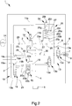
Figure 2 is the hydraulic diagram of a device for controlling the braking of a trailer according to the invention in a second embodiment. - With particular reference to these illustrations,
reference numeral 1 globally indicates a device for controlling the braking of a trailer. - The
device 1 comprises at least onemain line 2 connectable to a source of a work fluid at a first pressure, e.g. of the type of a positive displacement pump, at least asecondary line 3 separated from themain line 2, at least onedischarge line 4 of the work fluid connectable to adischarge tank 5, at least afirst line 6 connectable to the braking system of the trailer and at least asecond line 7 connectable to the automatic and/or parking brake of the trailer. - More specifically, the
first line 6 is connected to a firstmale coupling 8 of the towing vehicle, and thesecond line 7 is connected to a secondmale coupling 9 of the towing vehicle. The first and the secondmale couplings first line 6 in communication with the control line of the trailer, to convey the work fluid to the service braking system of the trailer, and thesecond line 7 with the additional line of the trailer, to convey the work fluid to the control device of the parking and/or automatic brake of the trailer itself for its deactivation. - The
device 1 then comprises first valve means 10 operable between a home position, in which thefirst line 6 is placed in communication with thedischarge line 4, and at least one braking position, in which thefirst line 6 is placed in communication with themain line 2, and first piloting means 11 of the first valve means 10. The first piloting means 11 comprise at least a first pilotingchannel 11a connectable to the braking system of a towing vehicle and actuating on the first valve means 10 to displace them from the home position to the braking position. In the embodiment shown in the illustrations, the first piloting means 11 also comprise firstelastic means 11b, which operate on the first valve means 10 in a concordant direction to thefirst piloting channel 11a, and acounteracting channel 11c communicating with thefirst line 6 and operating on the first valve means 10 from the opposite side with respect to thefirst piloting channel 11a. - The
device 1 also comprises second valve means 12 operable between a normal operating position, in which thesecond line 7 is placed in communication with thesecondary line 3, and an emergency position, in which thesecond line 7 is placed in communication with thedischarge line 4. - Conveniently, second piloting means 13 of the second valve means 12 are provided. The second piloting means 13 comprise at least a
second piloting channel 13a, adapted to interact with the second valve means 12 to displace them from the emergency position to the normal operating position, and at least onepiloting valve 13b which can be commanded between an inactive position, in which it places the second pilotingchannel 13a in communication with thedischarge line 4, and an active position, in which it places thesecond piloting channel 13a in communication with thesecondary line 3. - The
second piloting channel 13a operates on the second valve means 12 counteracting the secondelastic means 13c. - The second valve means 12 are therefore adapted to displace from the emergency position to the normal operating position as a result of the displacement of the
piloting valve 13b from the inactive position to the active position, this causing a corresponding increase in pressure along thesecond piloting channel 13a. - In turn the
piloting valve 13b is commanded by anelectromagnet 13d which counteracts furtherelastic means 13e which are adapted to keep the piloting valve itself in the inactive position until theelectromagnet 13d is commanded. - According to the invention, the
device 1 comprises at least oneaccumulator 14 of the work fluid connected to thesecondary line 3, at least third and fourth valve means 15 and 16, arranged in sequence with each other and interposed between themain line 2 and thesecondary line 3, where between the third and fourth valve means 15 and 16 is interposed at least oneintermediate line 17. The third valve means 15 are operable between a home position, in which themain line 2 is isolated from theintermediate line 17, and at least a first priority position, in which themain line 2 is placed in communication with theintermediate line 17, and the fourth valve means 16 are operable between a recharging position, in which theintermediate line 17 is placed in communication with thesecondary line 3 for enabling theaccumulator 14 to be recharged, and a stop position, in which theintermediate line 17 is isolated from thesecondary line 3. - More in detail, a recharging
line 18 is provided between the fourth valve means 16 and thesecondary line 3. Theintermediate line 17 is therefore placed in communication with the rechargingline 18 when the fourth valve means 16 are in the recharging position. - Therefore, when the third and the fourth valve means 15 and 16 are in the first priority position and in the recharging position respectively, the
main line 2 is placed in communication with thesecondary line 3 and, through it, with theaccumulator 14. In this operating condition themain line 2 is therefore able to recharge theaccumulator 14. - Advantageously, the
device 1 comprises third piloting means 19 of the third valve means 15. The third piloting means 19 comprise at least a third pilotingchannel 19a, communicating with themain line 2 and acting on the third valve means 15 to displace them from the home position to the first priority position, and at least one load sensingchannel 19b, which counteracts the third pilotingchannel 19a. - More particularly, the
load sensing channel 19b is connectable, e.g. through a so-calledflip flop 19c, to the line having higher pressure between thefirst line 6 and afurther piloting line 19d, which is communicating with theintermediate line 17 when the fourth valve means 16 are in the recharging position and with thedischarge line 4 when the fourth valve means 16 are in the stop position. Along theintermediate line 17 is arranged at least oneorifice 20a which is adapted to limit the flow of the work fluid to theaccumulator 14. - Preferably, even along at least one of the
further piloting line 19d and theload sensing channel 19b, anorifice 20b is arranged which is adapted to dampen the vibrations during the flow of the work fluid. - More in detail, in the recharging position, the
further piloting line 19d is communicating with theintermediate line 17, in turn communicating with the rechargingline 18, while in the stop position, theintermediate line 17 is closed and thefurther piloting line 19d is placed in communication with thedischarge line 4 and with therecharging line 18. - As can be seen from the illustrations, the fourth valve means 16 also have an intermediate position between the recharging position and the stop position, in which the
intermediate line 17 is placed in communication with therecharging line 18, so as to allow the recharge of theaccumulator 14 if there is enough pressure along theintermediate line 17, and thefurther piloting line 19d is placed in communication with thedischarge line 4 and is isolated from theintermediate line 17. - In the embodiment shown in the illustrations, the
load sensing channel 19b operates on the third valve means 15 in conjunction with the thirdelastic means 19e. - Preferably, the third valve means 15 also have a second priority position, subsequent to the first priority position away from the home position, in which the
main line 2 is placed in communication with theintermediate line 17 and with aservice line 21 connectable to a further user point. - Conveniently, the
device 1 also comprises fourth piloting means 22 of the fourth valve means 16. The fourth piloting means 22 comprise at least afourth piloting channel 22a communicating with thesecondary line 3 and adapted to push the fourth valve means 16 to displace them from the recharging position to the stop position. More in detail, thefourth piloting channel 22a is communicating with theaccumulator 14, e.g. by means of the rechargingline 18. The fourth piloting means 22 also comprise fourthelastic means 22b which operate on the fourth valve means 16 counteracting thefourth piloting channel 22a. - The
device 1 also comprises emergency valve means 24 interposed between thesecond piloting channel 13a and thedischarge line 4, which are activatable between an inactive position, in which they isolate thesecond piloting channel 13a from thedischarge line 4, and an active position, in which they place thesecond piloting channel 13a in communication with thedischarge line 4. Emergency piloting means 25 are also provided which are connected in a fluid operated manner to thefirst line 6. In the embodiment shown in the illustrations, the emergency piloting means 25 comprise at least a fluid operatedcylinder 25a inside which is housed sliding at least athrust element 25b on which operate, from opposite sides, afirst chamber 25c and asecond chamber 25d communicating with thefirst line 6. More in particular, along thefirst line 6 is arranged abottleneck 26 and the emergency piloting means 25 comprise at least afirst supply channel 25e for supplying thefirst chamber 25c and at least asecond supply channel 25f for supplying thesecond chamber 25d, where the first andsecond channels first line 6 upstream and downstream of thebottleneck 26 respectively. The terms "upstream" and "downstream" are used here to refer to the direction of forward movement of the work fluid along thefirst line 6, i.e. from the supply source towards the braking system of the trailer. - Along the first and the
second channels relative bottlenecks 27. - The emergency piloting means 25 then comprise at least one
operating element 25g, operatively connected to the emergency valve means 24 to push them from the inactive position to the active position, which is adapted to interact with thethrust element 25b following the pressure increase in thefirst chamber 25c with respect to thesecond chamber 25d. Thethrust element 25b then moves towards theoperating element 25g following the occurrence of a pressure difference between the first and thesecond channel first line 6. Suitably, inside thesecond chamber 25d elastic means 25h are housed adapted to counteract the displacement of thethrust element 25b towards theoperating element 25g. - The emergency piloting means 25 also comprise fifth
elastic means 25i which operate on the emergency valve means 24 counteracting theoperating element 25g. - The emergency piloting means 25 are therefore adapted to allow the operation of the automatic and/or parking brake of the trailer under emergency conditions, e.g., following a leak along the control line of the trailer, including in the case of the piloting
valve 13b being in the active position. - In the second embodiment shown in
Figure 2 , thedevice 1 comprises at least one connectingchannel 28 interposed between themain line 2 and thesecondary line 3, so as to allow the flow of the work fluid from theaccumulator 14 to thefirst line 6 and, therefore, a rapid activation of the service braking of the trailer also in the case of towing vehicles provided with small-sized pumps. Preferably, in this second embodiment, thedevice 1 comprises at least a first one-way valve 23 arranged along the connectingchannel 28 and adapted to prevent the flow of the work fluid from themain line 2 to thesecondary line 3. At least a second one-way valve 29 is also provided and arranged along themain line 2 upstream of the connectingchannel 28 and adapted to prevent the flow of the work fluid from the connecting channel itself to the source supplying the work fluid along themain line 2. More particularly, the second one-way valve 29 is arranged upstream (with reference to the direction of forward movement of the work fluid along the first line 6) of the interconnection area between themain line 2 and the connectingchannel 28. Suitably, thedevice 1 also comprises at least a third one-way valve 30 arranged along thesecondary line 3 and adapted to prevent the flow of the work fluid from thesecond line 7 to theaccumulator 14. More particularly, the third one-way valve 30 is arranged upstream (with reference to the direction of forward movement of the work fluid along the second line 7) of the second valve means 12, so as to prevent that a rapid drop in pressure along thefirst line 6 recalls the work fluid from thesecond line 7, thus causing the unwanted actuation of the automatic and/or parking brake of the trailer. - The operation of the present invention is as follows.
- When the towing vehicle is switched on, the first valve means 10 are in home position, so the pressure along the
first line 6 is substantially equal to zero. - The third and the fourth valve means 15 and 16 are, initially, in the home position and in the recharging position respectively.
- At the same time, the supply source of the work fluid is pressurized, causing the third valve means 15 to move towards the first priority position. This involves the work fluid passing along the
intermediate line 17 and, through it, towards theaccumulator 14, which is thus filled. - In the event of the third valve means 15 moving to the second priority position and of the
service line 21 requiring pressure, theintermediate line 17 is also pressurized and is therefore able to charge theaccumulator 14 through therecharging line 18. - When the
solenoid valve 13d is commanded, the pilotingvalve 13b moves from the inactive position to the active position, thus placing thesecond line 7 in communication with thesecondary line 3. - Due to the pressure present along the
secondary line 3, the second valve means 12 move from the emergency position to the normal operating position, thus allowing the work fluid present in theaccumulator 14 and that coming from therecharging line 18 to flow along thesecond line 7 and thus release the automatic and/or parking brake of the trailer. The presence of theaccumulator 14 therefore makes it possible to supply, in a short time, the flow rate of the work fluid required to release the automatic and/or parking brake of the trailer. - The fourth valve means 16 remain in the recharging position until the pressure along the
secondary line 3 reaches a predefined value and such that the pressure present along the fourth pilotingchannel 22a exceeds the force applied by the fourthelastic means 22b, at which point the fourth valve means move towards the stop position. - Conveniently, the calibration value of the fourth
elastic means 22b is close to the maximum pressure allowed by regulations and is equal to 35 bar. - This occurs, for example, when the
accumulator 14 is charged and the pressure of the work fluid along thesecond line 7 has caused the deactivation of the automatic and/or parking brake of the trailer. - When the automatic and/or parking brake of the trailer is deactivated, the fourth valve means 16 remain in the recharging position until the
accumulator 14 is fully recharged, after which the pressure along the fourth pilotingchannel 22a increases until the fourth valve means themselves are moved to the stop position. - In the event of the pressure along the main line rising further, and therefore also the thrust applied by the third piloting
channel 19a on the third valve means 15, the latter would move further to the second priority position in such a way that part of the work fluid flow rate flows towards theservice line 21. - The third valve means 15 return to the home position the instant the pressure along the
load sensing channel 19b reaches a predefined value such as, added to the force applied by the thirdelastic means 19e, to exceed the force applied on same third valve means 15 by the third pilotingchannel 19a. - When the service braking of the towing vehicle is applied, the pressure along the first piloting
channel 11a increases accordingly, thus causing the first valve means 10 to move from the home position towards the braking position. - After the first valve means 10 have reached the braking position, the work fluid coming from the
main line 2 flows along thefirst line 6 and consequently the service braking of the trailer is activated. - This operating condition also involves an increase in pressure along the counteracting
channel 11c, so the first valve means 10 are in an unstable balancing position in which the passage section of the work fluid from themain line 2 towards thefirst line 6 increases or decreases depending on the ratio between the forces acting on the first valve means themselves, and along theload sensing channel 19b. - In the second embodiment shown in
Figure 2 and described above, theaccumulator 14, thanks to the connectingchannel 28, allows supplying, in case of need, an increase in the flow rate of the work fluid towards thefirst line 6, thus obtaining a fast response of the service braking of the trailer. - It has in practice been ascertained that the described invention achieves the intended objects and, in particular, the fact is underlined that the device to which the present invention refers, thanks to the presence of the accumulator, of the third and fourth valve means, allows quickly deactivating the automatic and/or parking brake of the trailer, following the connection with the relative towing vehicle, also in the case of towing vehicles provided with small-sized supply pumps and, therefore, not able to supply enough fluid flow rate to supply the service braking of the trailer and deactivate the relative automatic and/or parking brake.
- In the second described embodiment, furthermore, the accumulator also makes it possible to reduce the response time of the service braking of the trailer following the braking of the towing vehicle.
Claims (11)
- Device (1) for controlling the braking of a trailer, comprising:- at least one main line (2) connectable to a source of a work fluid at a first pressure;- at least one secondary line (3) separated from said main line (2);- at least one discharge line (4) of the work fluid;- at least one first line (6) connectable to the braking system of the trailer;- at least one second line (7) connectable to the automatic and/or parking brake of the trailer;- first valve means (10) operable between a home position, in which said first line (6) is placed in communication with said discharge line (4), and a braking position, in which said first line (6) is placed in communication with said main line (2);- first piloting means (11) comprising at least a first piloting channel (11a) connectable to the braking system of a towing vehicle and actuating on the first valve means (10) to displace them from the home position to the braking position;- second valve means (12) operable between a normal operating position, in which said second line (7) is placed in communication with said secondary line (3), and an emergency position, in which said second line (7) is placed in communication with said discharge line (4);characterized by the fact that it comprises at least one accumulator (14) of the work fluid connected to said secondary line (3), and at least third and fourth valve means (15, 16) arranged in sequence with each other and interposed between said main line (2) and said secondary line (3), between said third and fourth valve means (15, 16) being interposed at least one intermediate line (17), wherein said third valve means (15) are operable between at least one home position, in which said main line (2) is isolated from said intermediate line (17), and at least one first priority position, in which said main line (2) is placed in communication with said intermediate line (17), and wherein said fourth valve means (16) are operable between at least one recharging position, in which said intermediate line (17) is placed in communication with said secondary line (3) for recharging said accumulator (14), and at least one stop position, in which said intermediate line (17) is isolated from said secondary line (3).
- Device (1) according to claim 1, characterized by the fact that it comprises second piloting means (13) comprising a second piloting channel (13a) acting on said second valve means (12) to displace them from the emergency position to the normal operating position, and at least one piloting valve (13b) which can be commanded between an inactive position, in which it places said second piloting channel (13a) in communication with said discharge line (4), and at least one active position, in which it places said second piloting channel (13a) in communication with said secondary line (3), said second valve means (12) displacing from the emergency position to the normal operating position as a result of the displacement of said piloting valve (13b) from the inactive position to the active position.
- Device (1) according to claim 1 or 2, characterized by the fact that it comprises third piloting means (19) comprising at least a third piloting channel (19a) communicating with said main line (2) and acting on said third valve means (15) to displace them from the home position to the first priority position, and at least one load sensing channel (19b) acting on said third valve means (15) on the opposite side of said third piloting channel (19a).
- Device (1) according to claim 3, characterized by the fact that said load sensing channel (19b) is connectable to the line having higher pressure between said first line (6) and a further piloting line (19d) communicating with said intermediate line (17) and with said discharge line (4) respectively with said fourth valve means (16) in the recharging position and in the stop position.
- Device (1) according to claim 4, characterized by the fact that it comprises at least one orifice (20a) arranged along said intermediate line (17) to limit the flow of the work fluid to said accumulator (14).
- Device (1) according to one or more of the preceding claims, characterized by the fact that said third valve means (15) have at least a second priority position, subsequent to said first priority position in the displacement from the home position, in which said main line (2) is placed in communication with said intermediate line (17) and with a service line (21) connectable to a further user point.
- Device (1) according to one or more of the preceding claims, characterized by the fact that it comprises fourth piloting means (22) comprising at least a fourth piloting channel (22a) communicating with said secondary line (3) and acting on said fourth valve means (16) to displace them from the recharging position to the stop position.
- Device (1) according to one or more of the preceding claims, characterized by the fact that it comprises at least one connecting channel (28) interposed between said main line (2) and said secondary line (3).
- Device (1) according to claim 9, characterized by the fact that it comprises at least a first one-way valve (23) arranged along said connecting channel (28) and adapted to prevent the flow of the work fluid from said main line (2) to said secondary line (3).
- Device (1) according to claim 9, characterized by the fact that it comprises at least a second one-way valve (29) arranged along said main line (2) upstream of said connecting channel (28) and adapted to prevent the flow of the work fluid from the connecting channel itself to said source of the work fluid.
- Device (1) according to claim 9 or 10, characterized by the fact that it comprises at least a third one-way valve (30) arranged along said secondary line (3) and interposed between said second valve means (12) and said connecting channel (28), said third one-way valve being adapted to prevent the flow of the work fluid from said second line (7) to said first line (6).
Applications Claiming Priority (1)
| Application Number | Priority Date | Filing Date | Title |
|---|---|---|---|
| IT102017000051943A IT201700051943A1 (en) | 2017-05-12 | 2017-05-12 | DEVICE FOR THE CONTROL OF THE BRAKING OF A TRAILER |
Publications (2)
| Publication Number | Publication Date |
|---|---|
| EP3401176A1 EP3401176A1 (en) | 2018-11-14 |
| EP3401176B1 true EP3401176B1 (en) | 2019-12-11 |
Family
ID=60020336
Family Applications (1)
| Application Number | Title | Priority Date | Filing Date |
|---|---|---|---|
| EP18171683.8A Active EP3401176B1 (en) | 2017-05-12 | 2018-05-10 | Device for controlling the braking of a trailer |
Country Status (2)
| Country | Link |
|---|---|
| EP (1) | EP3401176B1 (en) |
| IT (1) | IT201700051943A1 (en) |
Families Citing this family (2)
| Publication number | Priority date | Publication date | Assignee | Title |
|---|---|---|---|---|
| IT201900020296A1 (en) * | 2019-11-04 | 2021-05-04 | Safim S P A | DEVICE FOR CONTROLLING THE BRAKING OF A TRAILER |
| EP3988410A1 (en) * | 2020-10-22 | 2022-04-27 | Slanzi Oleodinamica S.r.l. | Circuit, valve and braking system for towing vehicles |
Family Cites Families (4)
| Publication number | Priority date | Publication date | Assignee | Title |
|---|---|---|---|---|
| AT408213B (en) * | 1999-03-16 | 2001-09-25 | Puehringer Hermann Ing | HYDRAULIC BRAKE SYSTEM |
| US20070102996A1 (en) * | 2005-11-10 | 2007-05-10 | Meritor Wabco Vehicle Control Systems | Hydraulic full power brake system for trailers |
| FR2895345B1 (en) * | 2005-12-23 | 2008-03-28 | Poclain Hydraulics Ind Soc Par | CONTROL OF THE HYDRAULIC BRAKE OF A TRAILER |
| FR3037023B1 (en) * | 2015-06-03 | 2018-06-22 | Poclain Hydraulics Industrie | HYDRAULIC BRAKE SYSTEM OF A VEHICLE WITH SEVERAL AXLES, ESPECIALLY A MULTI-AXLE TRAILER |
-
2017
- 2017-05-12 IT IT102017000051943A patent/IT201700051943A1/en unknown
-
2018
- 2018-05-10 EP EP18171683.8A patent/EP3401176B1/en active Active
Non-Patent Citations (1)
| Title |
|---|
| None * |
Also Published As
| Publication number | Publication date |
|---|---|
| EP3401176A1 (en) | 2018-11-14 |
| IT201700051943A1 (en) | 2018-11-12 |
Similar Documents
| Publication | Publication Date | Title |
|---|---|---|
| CN102762422B (en) | Brake fluid system and for running method and the control equipment of brake fluid system | |
| JP5516753B2 (en) | Hydraulic brake system | |
| JP5516752B2 (en) | Hydraulic brake system | |
| EP3401176B1 (en) | Device for controlling the braking of a trailer | |
| US10215280B2 (en) | Hydraulic system of an automatic transmission with multiple valve devices | |
| US9115702B2 (en) | Hydraulic control system | |
| CN102686457A (en) | Hydraulic vehicle braking system | |
| US5486040A (en) | Brake pressure controller for a hydraulic vehicle brake system | |
| US20160201746A1 (en) | Parking Brake | |
| US9863447B2 (en) | Master cylinder and master cylinder device | |
| CN101815638A (en) | Hydraulic power brake system | |
| EP3085590B1 (en) | Device for controlling the braking of a trailer | |
| HUT57134A (en) | Air brake system for vehicles and valve units for such air brake system | |
| EP3401175B1 (en) | Device for controlling the braking of a trailer | |
| EP3401177B1 (en) | Device for controlling a trailer-brake valve, connectable to the braking system of a trailer. | |
| EP3650293B1 (en) | Device for controlling the braking of a trailer | |
| EP3000672B1 (en) | Valve assembly for trailer | |
| EP2952398A1 (en) | Valve assembly | |
| EP3064408B1 (en) | Device for controlling the braking of a trailer | |
| EP3319848B1 (en) | Actuating device of a valve for the braking of a trailer | |
| EP4054907B1 (en) | Device for controlling the braking of a trailer | |
| EP3800097A1 (en) | Method, circuit, distributor and braking plant for towed vehicles | |
| JP7342106B2 (en) | System for charging and discharging at least one accumulator | |
| EP3231677B1 (en) | Device for controlling the braking of vehicles | |
| EP3085589B1 (en) | Valve assembly |
Legal Events
| Date | Code | Title | Description |
|---|---|---|---|
| PUAI | Public reference made under article 153(3) epc to a published international application that has entered the european phase |
Free format text: ORIGINAL CODE: 0009012 |
|
| STAA | Information on the status of an ep patent application or granted ep patent |
Free format text: STATUS: THE APPLICATION HAS BEEN PUBLISHED |
|
| AK | Designated contracting states |
Kind code of ref document: A1 Designated state(s): AL AT BE BG CH CY CZ DE DK EE ES FI FR GB GR HR HU IE IS IT LI LT LU LV MC MK MT NL NO PL PT RO RS SE SI SK SM TR |
|
| AX | Request for extension of the european patent |
Extension state: BA ME |
|
| STAA | Information on the status of an ep patent application or granted ep patent |
Free format text: STATUS: REQUEST FOR EXAMINATION WAS MADE |
|
| 17P | Request for examination filed |
Effective date: 20190510 |
|
| RBV | Designated contracting states (corrected) |
Designated state(s): AL AT BE BG CH CY CZ DE DK EE ES FI FR GB GR HR HU IE IS IT LI LT LU LV MC MK MT NL NO PL PT RO RS SE SI SK SM TR |
|
| GRAP | Despatch of communication of intention to grant a patent |
Free format text: ORIGINAL CODE: EPIDOSNIGR1 |
|
| STAA | Information on the status of an ep patent application or granted ep patent |
Free format text: STATUS: GRANT OF PATENT IS INTENDED |
|
| RIC1 | Information provided on ipc code assigned before grant |
Ipc: B60T 13/14 20060101AFI20190531BHEP |
|
| INTG | Intention to grant announced |
Effective date: 20190703 |
|
| GRAS | Grant fee paid |
Free format text: ORIGINAL CODE: EPIDOSNIGR3 |
|
| GRAA | (expected) grant |
Free format text: ORIGINAL CODE: 0009210 |
|
| STAA | Information on the status of an ep patent application or granted ep patent |
Free format text: STATUS: THE PATENT HAS BEEN GRANTED |
|
| AK | Designated contracting states |
Kind code of ref document: B1 Designated state(s): AL AT BE BG CH CY CZ DE DK EE ES FI FR GB GR HR HU IE IS IT LI LT LU LV MC MK MT NL NO PL PT RO RS SE SI SK SM TR |
|
| REG | Reference to a national code |
Ref country code: GB Ref legal event code: FG4D |
|
| REG | Reference to a national code |
Ref country code: CH Ref legal event code: EP |
|
| REG | Reference to a national code |
Ref country code: AT Ref legal event code: REF Ref document number: 1211898 Country of ref document: AT Kind code of ref document: T Effective date: 20191215 |
|
| REG | Reference to a national code |
Ref country code: DE Ref legal event code: R096 Ref document number: 602018001548 Country of ref document: DE |
|
| REG | Reference to a national code |
Ref country code: IE Ref legal event code: FG4D |
|
| REG | Reference to a national code |
Ref country code: NL Ref legal event code: MP Effective date: 20191211 |
|
| REG | Reference to a national code |
Ref country code: LT Ref legal event code: MG4D |
|
| PG25 | Lapsed in a contracting state [announced via postgrant information from national office to epo] |
Ref country code: LT Free format text: LAPSE BECAUSE OF FAILURE TO SUBMIT A TRANSLATION OF THE DESCRIPTION OR TO PAY THE FEE WITHIN THE PRESCRIBED TIME-LIMIT Effective date: 20191211 Ref country code: NO Free format text: LAPSE BECAUSE OF FAILURE TO SUBMIT A TRANSLATION OF THE DESCRIPTION OR TO PAY THE FEE WITHIN THE PRESCRIBED TIME-LIMIT Effective date: 20200311 Ref country code: GR Free format text: LAPSE BECAUSE OF FAILURE TO SUBMIT A TRANSLATION OF THE DESCRIPTION OR TO PAY THE FEE WITHIN THE PRESCRIBED TIME-LIMIT Effective date: 20200312 Ref country code: FI Free format text: LAPSE BECAUSE OF FAILURE TO SUBMIT A TRANSLATION OF THE DESCRIPTION OR TO PAY THE FEE WITHIN THE PRESCRIBED TIME-LIMIT Effective date: 20191211 Ref country code: BG Free format text: LAPSE BECAUSE OF FAILURE TO SUBMIT A TRANSLATION OF THE DESCRIPTION OR TO PAY THE FEE WITHIN THE PRESCRIBED TIME-LIMIT Effective date: 20200311 Ref country code: LV Free format text: LAPSE BECAUSE OF FAILURE TO SUBMIT A TRANSLATION OF THE DESCRIPTION OR TO PAY THE FEE WITHIN THE PRESCRIBED TIME-LIMIT Effective date: 20191211 Ref country code: SE Free format text: LAPSE BECAUSE OF FAILURE TO SUBMIT A TRANSLATION OF THE DESCRIPTION OR TO PAY THE FEE WITHIN THE PRESCRIBED TIME-LIMIT Effective date: 20191211 |
|
| PG25 | Lapsed in a contracting state [announced via postgrant information from national office to epo] |
Ref country code: HR Free format text: LAPSE BECAUSE OF FAILURE TO SUBMIT A TRANSLATION OF THE DESCRIPTION OR TO PAY THE FEE WITHIN THE PRESCRIBED TIME-LIMIT Effective date: 20191211 Ref country code: RS Free format text: LAPSE BECAUSE OF FAILURE TO SUBMIT A TRANSLATION OF THE DESCRIPTION OR TO PAY THE FEE WITHIN THE PRESCRIBED TIME-LIMIT Effective date: 20191211 |
|
| PG25 | Lapsed in a contracting state [announced via postgrant information from national office to epo] |
Ref country code: AL Free format text: LAPSE BECAUSE OF FAILURE TO SUBMIT A TRANSLATION OF THE DESCRIPTION OR TO PAY THE FEE WITHIN THE PRESCRIBED TIME-LIMIT Effective date: 20191211 |
|
| PG25 | Lapsed in a contracting state [announced via postgrant information from national office to epo] |
Ref country code: EE Free format text: LAPSE BECAUSE OF FAILURE TO SUBMIT A TRANSLATION OF THE DESCRIPTION OR TO PAY THE FEE WITHIN THE PRESCRIBED TIME-LIMIT Effective date: 20191211 Ref country code: NL Free format text: LAPSE BECAUSE OF FAILURE TO SUBMIT A TRANSLATION OF THE DESCRIPTION OR TO PAY THE FEE WITHIN THE PRESCRIBED TIME-LIMIT Effective date: 20191211 Ref country code: PT Free format text: LAPSE BECAUSE OF FAILURE TO SUBMIT A TRANSLATION OF THE DESCRIPTION OR TO PAY THE FEE WITHIN THE PRESCRIBED TIME-LIMIT Effective date: 20200506 Ref country code: CZ Free format text: LAPSE BECAUSE OF FAILURE TO SUBMIT A TRANSLATION OF THE DESCRIPTION OR TO PAY THE FEE WITHIN THE PRESCRIBED TIME-LIMIT Effective date: 20191211 Ref country code: ES Free format text: LAPSE BECAUSE OF FAILURE TO SUBMIT A TRANSLATION OF THE DESCRIPTION OR TO PAY THE FEE WITHIN THE PRESCRIBED TIME-LIMIT Effective date: 20191211 Ref country code: RO Free format text: LAPSE BECAUSE OF FAILURE TO SUBMIT A TRANSLATION OF THE DESCRIPTION OR TO PAY THE FEE WITHIN THE PRESCRIBED TIME-LIMIT Effective date: 20191211 |
|
| PG25 | Lapsed in a contracting state [announced via postgrant information from national office to epo] |
Ref country code: SK Free format text: LAPSE BECAUSE OF FAILURE TO SUBMIT A TRANSLATION OF THE DESCRIPTION OR TO PAY THE FEE WITHIN THE PRESCRIBED TIME-LIMIT Effective date: 20191211 Ref country code: IS Free format text: LAPSE BECAUSE OF FAILURE TO SUBMIT A TRANSLATION OF THE DESCRIPTION OR TO PAY THE FEE WITHIN THE PRESCRIBED TIME-LIMIT Effective date: 20200411 Ref country code: SM Free format text: LAPSE BECAUSE OF FAILURE TO SUBMIT A TRANSLATION OF THE DESCRIPTION OR TO PAY THE FEE WITHIN THE PRESCRIBED TIME-LIMIT Effective date: 20191211 |
|
| REG | Reference to a national code |
Ref country code: DE Ref legal event code: R097 Ref document number: 602018001548 Country of ref document: DE |
|
| REG | Reference to a national code |
Ref country code: AT Ref legal event code: MK05 Ref document number: 1211898 Country of ref document: AT Kind code of ref document: T Effective date: 20191211 |
|
| PLBE | No opposition filed within time limit |
Free format text: ORIGINAL CODE: 0009261 |
|
| STAA | Information on the status of an ep patent application or granted ep patent |
Free format text: STATUS: NO OPPOSITION FILED WITHIN TIME LIMIT |
|
| PG25 | Lapsed in a contracting state [announced via postgrant information from national office to epo] |
Ref country code: DK Free format text: LAPSE BECAUSE OF FAILURE TO SUBMIT A TRANSLATION OF THE DESCRIPTION OR TO PAY THE FEE WITHIN THE PRESCRIBED TIME-LIMIT Effective date: 20191211 |
|
| 26N | No opposition filed |
Effective date: 20200914 |
|
| PG25 | Lapsed in a contracting state [announced via postgrant information from national office to epo] |
Ref country code: SI Free format text: LAPSE BECAUSE OF FAILURE TO SUBMIT A TRANSLATION OF THE DESCRIPTION OR TO PAY THE FEE WITHIN THE PRESCRIBED TIME-LIMIT Effective date: 20191211 Ref country code: AT Free format text: LAPSE BECAUSE OF FAILURE TO SUBMIT A TRANSLATION OF THE DESCRIPTION OR TO PAY THE FEE WITHIN THE PRESCRIBED TIME-LIMIT Effective date: 20191211 |
|
| PG25 | Lapsed in a contracting state [announced via postgrant information from national office to epo] |
Ref country code: MC Free format text: LAPSE BECAUSE OF FAILURE TO SUBMIT A TRANSLATION OF THE DESCRIPTION OR TO PAY THE FEE WITHIN THE PRESCRIBED TIME-LIMIT Effective date: 20191211 |
|
| PG25 | Lapsed in a contracting state [announced via postgrant information from national office to epo] |
Ref country code: PL Free format text: LAPSE BECAUSE OF FAILURE TO SUBMIT A TRANSLATION OF THE DESCRIPTION OR TO PAY THE FEE WITHIN THE PRESCRIBED TIME-LIMIT Effective date: 20191211 |
|
| REG | Reference to a national code |
Ref country code: BE Ref legal event code: MM Effective date: 20200531 |
|
| PG25 | Lapsed in a contracting state [announced via postgrant information from national office to epo] |
Ref country code: LU Free format text: LAPSE BECAUSE OF NON-PAYMENT OF DUE FEES Effective date: 20200510 |
|
| PG25 | Lapsed in a contracting state [announced via postgrant information from national office to epo] |
Ref country code: IE Free format text: LAPSE BECAUSE OF NON-PAYMENT OF DUE FEES Effective date: 20200510 Ref country code: FR Free format text: LAPSE BECAUSE OF NON-PAYMENT OF DUE FEES Effective date: 20200531 |
|
| PG25 | Lapsed in a contracting state [announced via postgrant information from national office to epo] |
Ref country code: BE Free format text: LAPSE BECAUSE OF NON-PAYMENT OF DUE FEES Effective date: 20200531 |
|
| REG | Reference to a national code |
Ref country code: CH Ref legal event code: PL |
|
| PG25 | Lapsed in a contracting state [announced via postgrant information from national office to epo] |
Ref country code: LI Free format text: LAPSE BECAUSE OF NON-PAYMENT OF DUE FEES Effective date: 20210531 Ref country code: CH Free format text: LAPSE BECAUSE OF NON-PAYMENT OF DUE FEES Effective date: 20210531 |
|
| PG25 | Lapsed in a contracting state [announced via postgrant information from national office to epo] |
Ref country code: TR Free format text: LAPSE BECAUSE OF FAILURE TO SUBMIT A TRANSLATION OF THE DESCRIPTION OR TO PAY THE FEE WITHIN THE PRESCRIBED TIME-LIMIT Effective date: 20191211 Ref country code: MT Free format text: LAPSE BECAUSE OF FAILURE TO SUBMIT A TRANSLATION OF THE DESCRIPTION OR TO PAY THE FEE WITHIN THE PRESCRIBED TIME-LIMIT Effective date: 20191211 Ref country code: CY Free format text: LAPSE BECAUSE OF FAILURE TO SUBMIT A TRANSLATION OF THE DESCRIPTION OR TO PAY THE FEE WITHIN THE PRESCRIBED TIME-LIMIT Effective date: 20191211 |
|
| PG25 | Lapsed in a contracting state [announced via postgrant information from national office to epo] |
Ref country code: MK Free format text: LAPSE BECAUSE OF FAILURE TO SUBMIT A TRANSLATION OF THE DESCRIPTION OR TO PAY THE FEE WITHIN THE PRESCRIBED TIME-LIMIT Effective date: 20191211 |
|
| GBPC | Gb: european patent ceased through non-payment of renewal fee |
Effective date: 20220510 |
|
| PG25 | Lapsed in a contracting state [announced via postgrant information from national office to epo] |
Ref country code: GB Free format text: LAPSE BECAUSE OF NON-PAYMENT OF DUE FEES Effective date: 20220510 |
|
| P01 | Opt-out of the competence of the unified patent court (upc) registered |
Effective date: 20230527 |
|
| PGFP | Annual fee paid to national office [announced via postgrant information from national office to epo] |
Ref country code: IT Payment date: 20230522 Year of fee payment: 6 Ref country code: DE Payment date: 20230530 Year of fee payment: 6 |