EP3064408B1 - Device for controlling the braking of a trailer - Google Patents
Device for controlling the braking of a trailer Download PDFInfo
- Publication number
- EP3064408B1 EP3064408B1 EP16158783.7A EP16158783A EP3064408B1 EP 3064408 B1 EP3064408 B1 EP 3064408B1 EP 16158783 A EP16158783 A EP 16158783A EP 3064408 B1 EP3064408 B1 EP 3064408B1
- Authority
- EP
- European Patent Office
- Prior art keywords
- gap
- fact
- command
- channel
- communication
- Prior art date
- Legal status (The legal status is an assumption and is not a legal conclusion. Google has not performed a legal analysis and makes no representation as to the accuracy of the status listed.)
- Active
Links
- 239000012530 fluid Substances 0.000 claims description 31
- 238000000926 separation method Methods 0.000 claims description 4
- 230000036316 preload Effects 0.000 description 1
- 230000000284 resting effect Effects 0.000 description 1
Images


Classifications
-
- B—PERFORMING OPERATIONS; TRANSPORTING
- B60—VEHICLES IN GENERAL
- B60T—VEHICLE BRAKE CONTROL SYSTEMS OR PARTS THEREOF; BRAKE CONTROL SYSTEMS OR PARTS THEREOF, IN GENERAL; ARRANGEMENT OF BRAKING ELEMENTS ON VEHICLES IN GENERAL; PORTABLE DEVICES FOR PREVENTING UNWANTED MOVEMENT OF VEHICLES; VEHICLE MODIFICATIONS TO FACILITATE COOLING OF BRAKES
- B60T15/00—Construction arrangement, or operation of valves incorporated in power brake systems and not covered by groups B60T11/00 or B60T13/00
- B60T15/02—Application and release valves
-
- B—PERFORMING OPERATIONS; TRANSPORTING
- B60—VEHICLES IN GENERAL
- B60T—VEHICLE BRAKE CONTROL SYSTEMS OR PARTS THEREOF; BRAKE CONTROL SYSTEMS OR PARTS THEREOF, IN GENERAL; ARRANGEMENT OF BRAKING ELEMENTS ON VEHICLES IN GENERAL; PORTABLE DEVICES FOR PREVENTING UNWANTED MOVEMENT OF VEHICLES; VEHICLE MODIFICATIONS TO FACILITATE COOLING OF BRAKES
- B60T13/00—Transmitting braking action from initiating means to ultimate brake actuator with power assistance or drive; Brake systems incorporating such transmitting means, e.g. air-pressure brake systems
- B60T13/10—Transmitting braking action from initiating means to ultimate brake actuator with power assistance or drive; Brake systems incorporating such transmitting means, e.g. air-pressure brake systems with fluid assistance, drive, or release
- B60T13/66—Electrical control in fluid-pressure brake systems
- B60T13/662—Electrical control in fluid-pressure brake systems characterised by specified functions of the control system components
-
- B—PERFORMING OPERATIONS; TRANSPORTING
- B60—VEHICLES IN GENERAL
- B60T—VEHICLE BRAKE CONTROL SYSTEMS OR PARTS THEREOF; BRAKE CONTROL SYSTEMS OR PARTS THEREOF, IN GENERAL; ARRANGEMENT OF BRAKING ELEMENTS ON VEHICLES IN GENERAL; PORTABLE DEVICES FOR PREVENTING UNWANTED MOVEMENT OF VEHICLES; VEHICLE MODIFICATIONS TO FACILITATE COOLING OF BRAKES
- B60T13/00—Transmitting braking action from initiating means to ultimate brake actuator with power assistance or drive; Brake systems incorporating such transmitting means, e.g. air-pressure brake systems
- B60T13/10—Transmitting braking action from initiating means to ultimate brake actuator with power assistance or drive; Brake systems incorporating such transmitting means, e.g. air-pressure brake systems with fluid assistance, drive, or release
- B60T13/66—Electrical control in fluid-pressure brake systems
- B60T13/68—Electrical control in fluid-pressure brake systems by electrically-controlled valves
- B60T13/686—Electrical control in fluid-pressure brake systems by electrically-controlled valves in hydraulic systems or parts thereof
-
- B—PERFORMING OPERATIONS; TRANSPORTING
- B60—VEHICLES IN GENERAL
- B60T—VEHICLE BRAKE CONTROL SYSTEMS OR PARTS THEREOF; BRAKE CONTROL SYSTEMS OR PARTS THEREOF, IN GENERAL; ARRANGEMENT OF BRAKING ELEMENTS ON VEHICLES IN GENERAL; PORTABLE DEVICES FOR PREVENTING UNWANTED MOVEMENT OF VEHICLES; VEHICLE MODIFICATIONS TO FACILITATE COOLING OF BRAKES
- B60T15/00—Construction arrangement, or operation of valves incorporated in power brake systems and not covered by groups B60T11/00 or B60T13/00
- B60T15/02—Application and release valves
- B60T15/18—Triple or other relay valves which allow step-wise application or release and which are actuated by brake-pipe pressure variation to connect brake cylinders or equivalent to compressed air or vacuum source or atmosphere
-
- B—PERFORMING OPERATIONS; TRANSPORTING
- B60—VEHICLES IN GENERAL
- B60T—VEHICLE BRAKE CONTROL SYSTEMS OR PARTS THEREOF; BRAKE CONTROL SYSTEMS OR PARTS THEREOF, IN GENERAL; ARRANGEMENT OF BRAKING ELEMENTS ON VEHICLES IN GENERAL; PORTABLE DEVICES FOR PREVENTING UNWANTED MOVEMENT OF VEHICLES; VEHICLE MODIFICATIONS TO FACILITATE COOLING OF BRAKES
- B60T7/00—Brake-action initiating means
- B60T7/12—Brake-action initiating means for automatic initiation; for initiation not subject to will of driver or passenger
- B60T7/20—Brake-action initiating means for automatic initiation; for initiation not subject to will of driver or passenger specially for trailers, e.g. in case of uncoupling of or overrunning by trailer
Definitions
- the present invention relates to a device for controlling the braking of a trailer.
- the braking system of the trailer is therefore piloted by the braking system of the prime mover in order to synchronize the braking forces acting on same.
- the devices for braking a trailer of known type generally comprise a hollow body wherein are defined a plurality of gaps, among which a work fluid supply gap, a work fluid exhaust gap and a gap connectable to the positive braking system of the trailer.
- a distributor element is housed sliding, able to selectively place the braking gap in communication with the supply gap or the exhaust gap.
- the towing vehicles are connected to the respective trailer by means of a connecting device comprising a male joint associated with the towing vehicle and a corresponding female joint associated with the trailer.
- such connecting device allows to place the braking system of the towing vehicle in communication with the positive braking system of the trailer, so that the braking of the towing vehicle by the operator also causes the braking of the towed trailer.
- the braking system of the trailer is therefore piloted by the braking system of the prime mover in order to synchronize the braking forces acting on same.
- the connecting device between the towing vehicle and its trailer has a pair of male joints able to insert themselves inside a pair of relative female joints.
- the female joints are connectable to a control line able to supply the braking system of the trailer, and to an additional line able to disable the automatic and/or parking brake of the trailer itself, respectively.
- the additional line must be suitably connected to a drainage tank so as to allow the operation of the automatic and/or parking brake of the trailer and, therefore, the braking of same.
- a device for braking a trailer is known from WO 2014/001876 .
- the main aim of the present invention is to provide a device for controlling the braking of a trailer which allows at the same time to perform the functions of a trailer-brake valve and of managing the additional line in emergency situations.
- one object of the present invention is to allow the operation of the automatic and/or parking brake of the trailer also in the event of, following the turning off of the engine of the towing vehicle, the pressure along the additional line does not reset thus leaving the trailer without brakes.
- Another object of the present invention is to allow the operation of the automatic and/or parking brake of the trailer also in the event of no power supply in the trailer-brake valve.
- Yet another object of the present invention is to allow the intervention of the automatic and/or parking brake of the trailer after a predefined time in the event of a breakage occurring along the control line.
- a further object of the device to which the present invention refers is to allow the mechanical command of both the service braking and the emergency braking of the trailer.
- Another object of the present invention is to provide a device for controlling the braking of a trailer which allows to overcome the mentioned drawbacks of the prior art within the ambit of a simple, rational, easy, effective to use and affordable solution.
- reference number 1 globally indicates a device for controlling the braking of a trailer.
- the device 1 comprises a body 2 wherein is formed at least a first seat 3 communicating with at least a main gap 4 connectable to a source of a work fluid at a first pressure, with at least an exhaust gap 5 of the work fluid, and with at least a braking gap 6 communicating with at least a first line 7 connectable to the braking system of a trailer.
- unidirectional valve means are arranged, identified in the illustrations by the reference number 51, able to prevent the return of the work fluid towards the supply source of same.
- the first seat 3 is also communicating with at least a service gap 8 connectable to at least an external user point or in exhaust mode and/or with a load-sensing gap (not shown in the illustrations).
- a service gap 8 can be closed in the event of the work fluid being supplied by means of a variable flow rate pump.
- the first seat 3 can also be communicating with a load-sensing port.
- first distributor element 9 which is movable between at least an idle position, wherein the braking gap 6 is placed in communication with the exhaust gap 5, and at least a braking position, wherein the main gap 4 is placed in communication with the braking gap 6, so as to send the work fluid under pressure to the braking system of the trailer.
- the main gap 4 is placed in communication with the service gap 8 with the first distributor element 9 in the idle position.
- Piloting means 10 are also provided of the first distributor element 9 connectable to the braking system of a towing vehicle.
- the piloting means 10 comprise a piloting channel 11 connectable to the brake pump of the towing vehicle and acting on a piloting element 12 which in turn is able to interact with the first distributor element 9.
- piloting element 12 is arranged resting against a thrust element 13 which acts, by means of elastic means 14, on a connecting element 15 which in turn is able to interact with the first distributor element 9.
- the elastic means 14 are therefore able to apply a predefined force on the first distributor element 9 following the increase in pressure in the piloting channel 11 and, therefore, following the shift of the piloting element 12.
- the first distributor element 9 has a reaction surface communicating with the braking gap 6 and which acts in the opposite direction to the piloting means 10.
- first seat 3 inside the first seat 3 are defined two chambers, of which a first chamber 3a and a second chamber 3b, which act on the first distributor element 9 from opposite sides of same.
- first chamber 3a acts on the first distributor element 9 on the opposite side with respect to the piloting means 10.
- the chambers 3a and 3b are both communicating with the braking gap 6. More in detail, the chambers 3a and 3b are mutually communicating through a channel 16 obtained inside the first distributor element 9 and have mutually different thrust areas, the difference in which defines the above-mentioned reaction surface.
- the first distributor element 9 then moves from the idle position to the braking position in contrast to elastic means 17 arranged on the opposite side of the elastic means 14 with respect to the first distributor element itself.
- the elastic means 17 are housed inside the first chamber 3a and are interposed between the first distributor element 9 and an abutment element 18 arranged at the bottom of the first seat 3.
- the device 1 also comprises mechanical control means 19, operable to control the shift of the first distributor element 9 from the idle position to the braking position.
- control means 19 comprise at least a lever 20 arranged externally to the body 2, connectable to the parking brake of the towing vehicle and able to interact with the first distributor element 9.
- the lever 20 acts on a cam element 21 which has a tooth able to interact with the piloting element 12 by means of intermediate elastic means 61 not preloaded or having a preload below the elastic means 14.
- the intermediate elastic means 61 allow obtaining a command proportionate to the stroke of the lever 20.
- the cam element 21 is arranged outside the body 2 and interacts with a cup-shaped element 62 inside which the intermediate elastic means 61 are housed which in turn interact with the piloting element 12 by means of a roller 63.
- the lever 20 is therefore movable between a first work position, wherein the first distributor element 9 is free to move, and a second work position, wherein the first distributor element 9 is brought to the braking position due to the action applied on it by the elastic means 14 following the shift of the thrust element 13.
- a second seat 22 communicating with a secondary gap 23 connectable to a source of the work fluid at a second pressure, preferably lower than the aforementioned first pressure, with the exhaust gap 5 and with at least an additional gap 25 communicating with a second line 26 connectable to the automatic and/or parking brake of the trailer.
- a second distributor element 27 movable between a normal operating position, wherein the additional gap 25 is placed in communication with the secondary gap 23, and an emergency position, wherein the additional gap 25 is placed in communication with the exhaust gap 5 so as to allow the operation of the automatic and/or parking brake of the trailer.
- the device 1 comprises command means 31 of the shift of the second distributor element 27 from the normal operating position towards the emergency position.
- the command means 31 comprise at least a command channel 32, 33 communicating with the thrust chamber 28, connectable to the secondary gap 23 and to the exhaust gap 5 and valve means 34, 35, 36, 9 operable to place the command channel 32, 33 in communication at least with the exhaust gap 5, so as to permit the shift of the second distributor element 27 to the emergency position.
- the pressure in the thrust chamber 28 substantially resets thus allowing the shift of the second distributor element 27 to the emergency position and, therefore, the operation of the automatic and/or parking brake of the trailer.
- command means 31 comprise a first command channel 32 communicating with the thrust chamber 28 and connectable to the secondary gap 23 and first valve means 34 which can be operated to place the first command channel 32 in communication with at least with the exhaust gap 5.
- the command means 31 also comprise, in addition to the first command channel 32 communicating with the thrust chamber 28, a supply channel 37 communicating with the secondary gap 23; the first valve means 34 are interposed between the first command channel 32 and the supply channel 37 and are operable to selectively place the first command channel 32 in communication with the supply channel 37 or with the exhaust gap 5.
- the first valve means 34 are of the type of a three-way valve, two of which are composed of the first command channel 32 and of the supply channel 37, whereas the third one is composed of the connecting channel 38 connecting to the exhaust gap 5.
- the first command channel 32 is directly connected to the secondary gap 23.
- the first valve means 34 are of the type of a two-way valve, one of which is composed of the first command channel 32 and the other of the connecting channel 38 connecting to the exhaust gap 5, operable to isolate/place in communication the first command channel 32 from/with the exhaust gap 5.
- the first valve means 34 are preferably of the type of a solenoid valve operatively connected to at least one of the engine and the parking brake of the towing vehicle and able to place the first command channel 32 in communication with the exhaust gap 5 when the engine of the towing vehicle is stationary or when the parking brake is operated, respectively.
- a narrowing 39 able to reduce the flow rate of the work fluid towards the thrust chamber itself, so as to ensure that the pressure inside it resets following the operation of the valve means 34,35,36,9, the exhaust gap 5 (and the channels connected to it) having a greater area.
- the device 1 also comprises pressure limiting means for limiting the pressure, identified by the reference number 40 in Figure 2 , interposed between the secondary gap 23 and the second seat 22. More particularly, the pressure limiting means 40 are able to isolate the secondary gap 23 from the second seat 22 in the event of the pressure of the work fluid crossing it exceeds a predefined value.
- the command means 31 also comprise second valve means 35 manually operable by an operator to place the first command channel 32 in communication with the exhaust gap 5.
- the second valve means 35 can be provided in addition or alternatively, as is the case of Figure 4 , to the first valve means 34.
- the second valve means 35 are manually movable between a first configuration, wherein they place the supply channel 37 in communication with the first command channel 32, and a second configuration, wherein they place the first command channel itself in communication with the connecting channel 38.
- the body 2 may also have an auxiliary port 50, not shown in the illustrations, communicating with the first command channel 32 and usable by an operator to connect it to an external user point in order to drain the work fluid coming from the secondary gap 23.
- command means 31 also comprise third valve means 36 operable to place the thrust chamber 28 in communication with the exhaust gap 5 following a pressure drop along the first line 7, e.g. caused by a breakage along the control line.
- the command means 31 comprise at least a third seat 41 formed in the body 2 and within which is housed sliding at least an actuator element 42 which splits the third seat 41 into a first chamber 41a communicating with a first length 7a of the first line 7 and into a second chamber 41b communicating with a second length 7b of the first line itself and arranged downstream of the first length 7a. Between the first and the second length 7a and 7b is conveniently interposed a calibrated orifice 43 which affects the intervention time of the actuator element 42.
- the actuator element 42 shifts in contrast to the elastic means 49 arranged inside the second chamber 41b.
- the command means 31 also comprise a second command channel 33 communicating with the thrust chamber 28, an exhaust channel 44 communicating with the exhaust gap 5; the third valve means 36 are able to place in communication/isolate the second command channel 33 with/from the exhaust channel 44.
- the second command channel 33 is in communication by means of the thrust chamber 28 with the first command channel 32, the pressure of the work fluid is therefore the same. It follows therefore that the pressure inside the thrust chamber 28 resets following the exhaust connection of each of the two command channels 32, 33.
- the actuator element 42 is able to shift, due to the reaching of a predefined pressure difference between the first and the second length 7a and 7b, from an inactive position, wherein it does not interact with the third valve means 36, to an active position, wherein it intervenes on the third valve means 36 to place the second command channel 33 in communication with the exhaust channel 44, so as to exhaust the work fluid contained in the thrust chamber 28 and allow the shift of the second distributor element 27 to the emergency position.
- the third valve means 36 comprise at least a shutter 36a protruding into the second chamber 41b and which is able to be intercepted by the actuator element 42 in its shift from the inactive position to the active position so as to place the second command channel 33 in communication with the exhaust channel 44.
- the second and third seat 22 and 41 are communicating together and a separation element 45 is interposed between them and is able to isolate fluid-dynamically the seat themselves, and the shutter 36a is inserted sealed in a sliding manner inside the separation element 45.
- a narrowing 52 is interposed between the first length 7a and the first chamber 41a and/or between the second length 7b and the second chamber 41b which is able to slow down the intervention time of the actuator element 42.
- the intervention time of the actuator element 42 also depends on the stiffness of the elastic means 49, on the relevant thrust areas on which the chambers 41a and 41b act and on the length of its stroke.
- the first seat 3 also comprises an emergency gap 46 and the first distributor element 9 has an emergency position wherein the emergency gap itself is placed in communication with the exhaust gap 5.
- the lack of pressure in the chamber 3a able to counterbalance the force applied by the elastic means 14 entails an overrun of the first distributor element itself.
- the first distributor element 9 contacts the abutment element 18, on which act further elastic means 47 able to counteract the shift of the first distributor element itself towards the emergency position.
- the elastic means 47 are able to absorb at least part of the force applied by the elastic means 14, so as to slow down the shift of the first distributor element 9 towards the emergency position.
- the further elastic means 47 are arranged inside a further chamber 53 arranged on the opposite side of the first chamber 3a with respect to the abutment element 18.
- the abutment element 18 also defines a transit channel 54 able to place the first chamber 3a in communication with the further chamber 53 and along which at least one narrowing 55 is defined.
- the command means 31 also comprise at least an intermediate channel 48 communicating on one side with the emergency gap 46 and on the other side with the first command channel 32 and fourth valve means able to place the first command channel itself with the exhaust gap 5.
- the fourth valve means are defined by the first distributor element 9 which, by placing the emergency gap 46 in communication with the exhaust gap 5 in its emergency position, enables the drainage of the work fluid contained in the first command channel 32.
- the command means 31 may also comprise further valve means 56 arranged along the intermediate channel 48 and able to slow down the intervention time of the automatic and/or parking brake of the trailer.
- the further valve means 56 are able to shift themselves from a first position, wherein they interrupt the connection between the emergency gap 46 and the first command channel 32, and a second position, wherein they place the emergency gap 46 in communication with the first command channel itself to allow the drainage of the work fluid from the thrust chamber 28 towards the exhaust gap 5 following the reaching of the emergency position by the first distributor element 9.
- the further valve means 56 comprise a further distributor element 57 housed sliding inside a further seat 58 defined in the body 2 and communicating on one side with the secondary gap 23 and on the other side with the emergency gap 46.
- the further distributor element 57 divides the further seat 58 into two chambers opposite one another and communicating through a narrowing 59 and also has an inner channel 60 able to place the emergency gap 46 in communication with the first command channel 32 upon reaching the second work position.
- the first distributor element 9 In normal operating conditions, as long as the brakes of the towing vehicle are not operated, the first distributor element 9 is in idle position, so that the main gap 4 is placed in communication with the service gap 8 and the braking gap 6 is placed in communication with the exhaust gap 5.
- the piloting element 12 acts on the thrust element 13 which, by shifting, compresses the elastic means 14 which, consequently, by means of the connecting element 15, push the first distributor element 9 towards the braking position.
- the narrowing occurs of the connection between the main gap 4 and the service gap 8, thereby causing an increase in pressure in the main gap itself.
- the main gap 4 is placed in communication with the braking gap 6.
- the first distributor element 9 then reaches a position of equilibrium wherein the force applied by the elastic means 14 is balanced by the force due to the pressure in the chambers 3a and 3b and to the elastic means 17.
- the unidirectional valve means 51 arranged at the main gap 4 prevent the outflow of the work fluid under pressure from the braking system of the trailer towards the supply source.
- the lever 20 moves from the first work position to the second work position consequently causing the shift of the thrust element 13 and, therefore, the braking of the trailer.
- the second distributor element 27 takes up a normal operating position, wherein the additional gap 25 is placed in communication with the secondary gap 23, in such a way as to maintain the automatic and/or parking brake of the trailer disabled.
- the thrust chamber 28 is connected, by means of the first command channel 32 to the secondary gap 23, so that the pressure inside it is such as to overcome the force applied by the elastic means 30.
- the first command channel 32 is placed in communication with the supply channel 37 through the solenoid valve 34 when the engine of the towing vehicle is operating whereas, following its being turned off, e.g. after a predefined time interval in case the pressure along the additional line does not quickly reset, or following the operation of the relative parking brake, the solenoid valve itself places the first command channel 32 in communication with the connecting channel 38, thereby enabling the work fluid contained in the thrust chamber 28 to be drained off and enabling the second distributor element 27 to shift to the emergency position. As described above, such shift involves the operation of the automatic and/or parking brake of the trailer.
- the first command channel 32 is constantly in communication with the secondary gap 23 and the solenoid valve 34 which, in normal operating condition (i.e., with the engine of the towing vehicle running) keeps the first command channel 32 isolated from the exhaust gap 5, and is able to place the first command channel 32 in communication with the exhaust gap itself following the switching off of the engine of the towing vehicle or following the operation of its parking brake, in such a way as to drain the work fluid coming from the secondary gap 23 and allow the operation of the automatic and/or parking brake of the trailer.
- the solenoid valve 34 which, in normal operating condition (i.e., with the engine of the towing vehicle running) keeps the first command channel 32 isolated from the exhaust gap 5, and is able to place the first command channel 32 in communication with the exhaust gap itself following the switching off of the engine of the towing vehicle or following the operation of its parking brake, in such a way as to drain the work fluid coming from the secondary gap 23 and allow the operation of the automatic and/or parking brake of the trailer.
- the exhaust connection of the work fluid contained in the thrust chamber 28 can also be obtained in the following ways: by means of the manual operation of the second valve means 35, by means of the connection of an external user point to the auxiliary port 50, by means of the third valve means 36 following a drop in pressure generated by the loss of the work fluid along the first line 7, or by the reaching of the braking position by the first distributor element 9 following the lack of supply of the work fluid from the main gap 4.
- the actuator element 42 shifts until it contacts the shutter 36a, in such a way as to place the second command channel 33 in communication with the exhaust channel 44 and, therefore, with the exhaust gap 5.
- the first distributor element 9 performs an overrun towards the abutment element 18 and moves to the emergency position thus placing the emergency gap 46, and consequently also the first command channel 32 through the intermediate channel 48, in communication with the exhaust gap 5.
- a solenoid valve operatively connected to the control system of the engine of the towing vehicle also permits operating the automatic and/or parking brake of the trailer also in the event of the switching off of the engine of the towing vehicle not resulting in the automatic pressure reset along the additional line.
- the device to which the present invention refers allows the emergency braking of the trailer in three distinct conditions, i.e., in case of no supply of work fluid through the main gap, in case of leaks along the braking system of the trailer or in the case of mechanical command by means of the handbrake lever.
Landscapes
- Engineering & Computer Science (AREA)
- Transportation (AREA)
- Mechanical Engineering (AREA)
- Valves And Accessory Devices For Braking Systems (AREA)
- Regulating Braking Force (AREA)
Description
- The present invention relates to a device for controlling the braking of a trailer.
- It is known that in the case of a trailer towed by a prime mover their braking systems are operatively connected in such a way that the braking of the prime mover by the operator also causes the braking of the towed trailer.
- The braking system of the trailer is therefore piloted by the braking system of the prime mover in order to synchronize the braking forces acting on same.
- It follows, therefore, that when the operator operates the brake pedal of the prime mover, this operates on the wheels of same and, by means of a braking valve (called trailer-brake valve), also on the braking system of the trailer.
- The devices for braking a trailer of known type generally comprise a hollow body wherein are defined a plurality of gaps, among which a work fluid supply gap, a work fluid exhaust gap and a gap connectable to the positive braking system of the trailer. Inside this hollow body, a distributor element is housed sliding, able to selectively place the braking gap in communication with the supply gap or the exhaust gap.
- As known, to date the towing vehicles are connected to the respective trailer by means of a connecting device comprising a male joint associated with the towing vehicle and a corresponding female joint associated with the trailer.
- More particularly, such connecting device allows to place the braking system of the towing vehicle in communication with the positive braking system of the trailer, so that the braking of the towing vehicle by the operator also causes the braking of the towed trailer.
- The braking system of the trailer is therefore piloted by the braking system of the prime mover in order to synchronize the braking forces acting on same.
- Some recent regulations provide that the connecting device between the towing vehicle and its trailer has a pair of male joints able to insert themselves inside a pair of relative female joints.
- In particular, the female joints are connectable to a control line able to supply the braking system of the trailer, and to an additional line able to disable the automatic and/or parking brake of the trailer itself, respectively. In emergency situations, the additional line must be suitably connected to a drainage tank so as to allow the operation of the automatic and/or parking brake of the trailer and, therefore, the braking of same.
- A device for braking a trailer is known from
WO 2014/001876 . - The main aim of the present invention is to provide a device for controlling the braking of a trailer which allows at the same time to perform the functions of a trailer-brake valve and of managing the additional line in emergency situations.
- Within this aim, one object of the present invention is to allow the operation of the automatic and/or parking brake of the trailer also in the event of, following the turning off of the engine of the towing vehicle, the pressure along the additional line does not reset thus leaving the trailer without brakes.
- Another object of the present invention is to allow the operation of the automatic and/or parking brake of the trailer also in the event of no power supply in the trailer-brake valve.
- Yet another object of the present invention is to allow the intervention of the automatic and/or parking brake of the trailer after a predefined time in the event of a breakage occurring along the control line.
- A further object of the device to which the present invention refers is to allow the mechanical command of both the service braking and the emergency braking of the trailer.
- Another object of the present invention is to provide a device for controlling the braking of a trailer which allows to overcome the mentioned drawbacks of the prior art within the ambit of a simple, rational, easy, effective to use and affordable solution.
- The above mentioned objects are achieved by the present device for controlling the braking of a trailer according to
claim 1. - Other characteristics and advantages of the present invention will become better evident from the description of a preferred, but not exclusive, embodiment of a device for controlling the braking of a trailer, illustrated by way of an indicative but non-limiting example in the accompanying drawings, wherein:
-
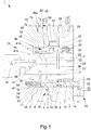
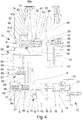
Figures 1 to 5 are sectional views of alternative embodiments of a device according to the invention. - With particular reference to such illustrations,
reference number 1 globally indicates a device for controlling the braking of a trailer. - The
device 1 comprises abody 2 wherein is formed at least afirst seat 3 communicating with at least amain gap 4 connectable to a source of a work fluid at a first pressure, with at least anexhaust gap 5 of the work fluid, and with at least abraking gap 6 communicating with at least afirst line 7 connectable to the braking system of a trailer. - Advantageously, at the
main gap 4 unidirectional valve means are arranged, identified in the illustrations by thereference number 51, able to prevent the return of the work fluid towards the supply source of same. - In the embodiment shown in the illustrations, the
first seat 3 is also communicating with at least aservice gap 8 connectable to at least an external user point or in exhaust mode and/or with a load-sensing gap (not shown in the illustrations).Such service gap 8 can be closed in the event of the work fluid being supplied by means of a variable flow rate pump. - In a further embodiment, not shown in the illustrations, the
first seat 3 can also be communicating with a load-sensing port. - Within the
first seat 3 is housed in a sliding manner afirst distributor element 9, which is movable between at least an idle position, wherein thebraking gap 6 is placed in communication with theexhaust gap 5, and at least a braking position, wherein themain gap 4 is placed in communication with thebraking gap 6, so as to send the work fluid under pressure to the braking system of the trailer. - In the embodiments shown in the illustrations, the
main gap 4 is placed in communication with theservice gap 8 with thefirst distributor element 9 in the idle position. - Piloting means 10 are also provided of the
first distributor element 9 connectable to the braking system of a towing vehicle. - The piloting means 10 comprise a piloting
channel 11 connectable to the brake pump of the towing vehicle and acting on apiloting element 12 which in turn is able to interact with thefirst distributor element 9. - More particularly, the piloting
element 12 is arranged resting against athrust element 13 which acts, by means ofelastic means 14, on a connectingelement 15 which in turn is able to interact with thefirst distributor element 9. - The
elastic means 14 are therefore able to apply a predefined force on thefirst distributor element 9 following the increase in pressure in the pilotingchannel 11 and, therefore, following the shift of thepiloting element 12. - The
first distributor element 9 has a reaction surface communicating with thebraking gap 6 and which acts in the opposite direction to the piloting means 10. - In the embodiments shown in the illustrations, inside the
first seat 3 are defined two chambers, of which afirst chamber 3a and asecond chamber 3b, which act on thefirst distributor element 9 from opposite sides of same. As can be seen in the illustrations, thefirst chamber 3a acts on thefirst distributor element 9 on the opposite side with respect to the piloting means 10. - The
chambers braking gap 6. More in detail, thechambers channel 16 obtained inside thefirst distributor element 9 and have mutually different thrust areas, the difference in which defines the above-mentioned reaction surface. - The
first distributor element 9 then moves from the idle position to the braking position in contrast toelastic means 17 arranged on the opposite side of theelastic means 14 with respect to the first distributor element itself. - More particularly, the
elastic means 17 are housed inside thefirst chamber 3a and are interposed between thefirst distributor element 9 and anabutment element 18 arranged at the bottom of thefirst seat 3. - The
device 1 also comprises mechanical control means 19, operable to control the shift of thefirst distributor element 9 from the idle position to the braking position. - In the embodiment shown in
figure 3 , the control means 19 comprise at least alever 20 arranged externally to thebody 2, connectable to the parking brake of the towing vehicle and able to interact with thefirst distributor element 9. - More particularly, the
lever 20 acts on acam element 21 which has a tooth able to interact with thepiloting element 12 by means of intermediate elastic means 61 not preloaded or having a preload below theelastic means 14. The intermediate elastic means 61 allow obtaining a command proportionate to the stroke of thelever 20. - In the embodiment shown in
figure 3 , thecam element 21 is arranged outside thebody 2 and interacts with a cup-shaped element 62 inside which the intermediate elastic means 61 are housed which in turn interact with thepiloting element 12 by means of a roller 63. - The
lever 20 is therefore movable between a first work position, wherein thefirst distributor element 9 is free to move, and a second work position, wherein thefirst distributor element 9 is brought to the braking position due to the action applied on it by theelastic means 14 following the shift of thethrust element 13. - According to the invention, within the
body 2 is also formed asecond seat 22 communicating with asecondary gap 23 connectable to a source of the work fluid at a second pressure, preferably lower than the aforementioned first pressure, with theexhaust gap 5 and with at least anadditional gap 25 communicating with asecond line 26 connectable to the automatic and/or parking brake of the trailer. - Within the
second seat 22 is housed in a sliding manner at least asecond distributor element 27 movable between a normal operating position, wherein theadditional gap 25 is placed in communication with thesecondary gap 23, and an emergency position, wherein theadditional gap 25 is placed in communication with theexhaust gap 5 so as to allow the operation of the automatic and/or parking brake of the trailer. - On the
second distributor element 27 act, on opposite sides, athrust chamber 28 and acontrast chamber 29, where within the latter are housedelastic means 30 which are able to push the second distributor element itself towards the emergency position. - Still according to the invention, the
device 1 comprises command means 31 of the shift of thesecond distributor element 27 from the normal operating position towards the emergency position. - Advantageously, the command means 31 comprise at least a
command channel thrust chamber 28, connectable to thesecondary gap 23 and to theexhaust gap 5 and valve means 34, 35, 36, 9 operable to place thecommand channel exhaust gap 5, so as to permit the shift of thesecond distributor element 27 to the emergency position. - More in particular, following the connection of the
command channel exhaust gap 5 due to the operation of the valve means 34,35,36,9, the pressure in thethrust chamber 28 substantially resets thus allowing the shift of thesecond distributor element 27 to the emergency position and, therefore, the operation of the automatic and/or parking brake of the trailer. - More in particular, the command means 31 comprise a
first command channel 32 communicating with thethrust chamber 28 and connectable to thesecondary gap 23 and first valve means 34 which can be operated to place thefirst command channel 32 in communication with at least with theexhaust gap 5. - In the embodiments shown in the
Figures 1 to 4 , the command means 31 also comprise, in addition to thefirst command channel 32 communicating with thethrust chamber 28, asupply channel 37 communicating with thesecondary gap 23; the first valve means 34 are interposed between thefirst command channel 32 and thesupply channel 37 and are operable to selectively place thefirst command channel 32 in communication with thesupply channel 37 or with theexhaust gap 5. In this case, the first valve means 34 are of the type of a three-way valve, two of which are composed of thefirst command channel 32 and of thesupply channel 37, whereas the third one is composed of the connectingchannel 38 connecting to theexhaust gap 5. - In the embodiment shown in
Figure 5 , on the contrary, thefirst command channel 32 is directly connected to thesecondary gap 23. More in detail, in this embodiment, the first valve means 34 are of the type of a two-way valve, one of which is composed of thefirst command channel 32 and the other of the connectingchannel 38 connecting to theexhaust gap 5, operable to isolate/place in communication thefirst command channel 32 from/with theexhaust gap 5. - In both embodiments described therein, the first valve means 34 are preferably of the type of a solenoid valve operatively connected to at least one of the engine and the parking brake of the towing vehicle and able to place the
first command channel 32 in communication with theexhaust gap 5 when the engine of the towing vehicle is stationary or when the parking brake is operated, respectively. - In both embodiments, furthermore, between the
secondary gap 23 and thethrust chamber 28 is interposed a narrowing 39 able to reduce the flow rate of the work fluid towards the thrust chamber itself, so as to ensure that the pressure inside it resets following the operation of the valve means 34,35,36,9, the exhaust gap 5 (and the channels connected to it) having a greater area. - Conveniently, the
device 1 also comprises pressure limiting means for limiting the pressure, identified by thereference number 40 inFigure 2 , interposed between thesecondary gap 23 and thesecond seat 22. More particularly, the pressure limiting means 40 are able to isolate thesecondary gap 23 from thesecond seat 22 in the event of the pressure of the work fluid crossing it exceeds a predefined value. - Preferably, the command means 31 also comprise second valve means 35 manually operable by an operator to place the
first command channel 32 in communication with theexhaust gap 5. - The second valve means 35 can be provided in addition or alternatively, as is the case of
Figure 4 , to the first valve means 34. - In this embodiment, the second valve means 35 are manually movable between a first configuration, wherein they place the
supply channel 37 in communication with thefirst command channel 32, and a second configuration, wherein they place the first command channel itself in communication with the connectingchannel 38. - The
body 2 may also have anauxiliary port 50, not shown in the illustrations, communicating with thefirst command channel 32 and usable by an operator to connect it to an external user point in order to drain the work fluid coming from thesecondary gap 23. - Advantageously, the command means 31 also comprise third valve means 36 operable to place the
thrust chamber 28 in communication with theexhaust gap 5 following a pressure drop along thefirst line 7, e.g. caused by a breakage along the control line. - More in detail, the command means 31 comprise at least a
third seat 41 formed in thebody 2 and within which is housed sliding at least anactuator element 42 which splits thethird seat 41 into afirst chamber 41a communicating with afirst length 7a of thefirst line 7 and into asecond chamber 41b communicating with asecond length 7b of the first line itself and arranged downstream of thefirst length 7a. Between the first and thesecond length orifice 43 which affects the intervention time of theactuator element 42. Theactuator element 42 shifts in contrast to the elastic means 49 arranged inside thesecond chamber 41b. - The command means 31 also comprise a
second command channel 33 communicating with thethrust chamber 28, anexhaust channel 44 communicating with theexhaust gap 5; the third valve means 36 are able to place in communication/isolate thesecond command channel 33 with/from theexhaust channel 44. - It is pointed out that the
second command channel 33 is in communication by means of thethrust chamber 28 with thefirst command channel 32, the pressure of the work fluid is therefore the same. It follows therefore that the pressure inside thethrust chamber 28 resets following the exhaust connection of each of the twocommand channels - The
actuator element 42 is able to shift, due to the reaching of a predefined pressure difference between the first and thesecond length second command channel 33 in communication with theexhaust channel 44, so as to exhaust the work fluid contained in thethrust chamber 28 and allow the shift of thesecond distributor element 27 to the emergency position. - More particularly, the third valve means 36 comprise at least a
shutter 36a protruding into thesecond chamber 41b and which is able to be intercepted by theactuator element 42 in its shift from the inactive position to the active position so as to place thesecond command channel 33 in communication with theexhaust channel 44. - Conveniently, the second and
third seat separation element 45 is interposed between them and is able to isolate fluid-dynamically the seat themselves, and theshutter 36a is inserted sealed in a sliding manner inside theseparation element 45. - Preferably, between the
first length 7a and thefirst chamber 41a and/or between thesecond length 7b and thesecond chamber 41b a narrowing 52 is interposed which is able to slow down the intervention time of theactuator element 42. - More in detail, the intervention time of the
actuator element 42 also depends on the stiffness of the elastic means 49, on the relevant thrust areas on which thechambers - Advantageously, the
first seat 3 also comprises anemergency gap 46 and thefirst distributor element 9 has an emergency position wherein the emergency gap itself is placed in communication with theexhaust gap 5. - More particularly, in the case of no work fluid coming from the
main gap 4 and, simultaneously, the operator operating the brakes of the towing vehicle thereby causing the operation of the pilotingmeans 10 and the consequent shift of thefirst distributor element 9 from the idle position to the braking position, the lack of pressure in thechamber 3a able to counterbalance the force applied by the elastic means 14 entails an overrun of the first distributor element itself. - Following such overrun, the
first distributor element 9 contacts theabutment element 18, on which act further elastic means 47 able to counteract the shift of the first distributor element itself towards the emergency position. The elastic means 47 are able to absorb at least part of the force applied by the elastic means 14, so as to slow down the shift of thefirst distributor element 9 towards the emergency position. - The further
elastic means 47 are arranged inside afurther chamber 53 arranged on the opposite side of thefirst chamber 3a with respect to theabutment element 18. - Preferably, the
abutment element 18 also defines atransit channel 54 able to place thefirst chamber 3a in communication with thefurther chamber 53 and along which at least one narrowing 55 is defined. - The command means 31 also comprise at least an
intermediate channel 48 communicating on one side with theemergency gap 46 and on the other side with thefirst command channel 32 and fourth valve means able to place the first command channel itself with theexhaust gap 5. - In this case, the fourth valve means are defined by the
first distributor element 9 which, by placing theemergency gap 46 in communication with theexhaust gap 5 in its emergency position, enables the drainage of the work fluid contained in thefirst command channel 32. - In a particular embodiment, shown in
figure 4 , the command means 31 may also comprise further valve means 56 arranged along theintermediate channel 48 and able to slow down the intervention time of the automatic and/or parking brake of the trailer. - The further valve means 56 are able to shift themselves from a first position, wherein they interrupt the connection between the
emergency gap 46 and thefirst command channel 32, and a second position, wherein they place theemergency gap 46 in communication with the first command channel itself to allow the drainage of the work fluid from thethrust chamber 28 towards theexhaust gap 5 following the reaching of the emergency position by thefirst distributor element 9. More particularly, the further valve means 56 comprise afurther distributor element 57 housed sliding inside a further seat 58 defined in thebody 2 and communicating on one side with thesecondary gap 23 and on the other side with theemergency gap 46. Thefurther distributor element 57 divides the further seat 58 into two chambers opposite one another and communicating through a narrowing 59 and also has aninner channel 60 able to place theemergency gap 46 in communication with thefirst command channel 32 upon reaching the second work position. - The operation of the present invention is as follows.
- In normal operating conditions, as long as the brakes of the towing vehicle are not operated, the
first distributor element 9 is in idle position, so that themain gap 4 is placed in communication with theservice gap 8 and thebraking gap 6 is placed in communication with theexhaust gap 5. - Following the operation of the brakes of the towing vehicle, due to the increasing pressure in the piloting
channel 11, the pilotingelement 12 acts on thethrust element 13 which, by shifting, compresses the elastic means 14 which, consequently, by means of the connectingelement 15, push thefirst distributor element 9 towards the braking position. Following the shift of thefirst distributor element 9 the narrowing occurs of the connection between themain gap 4 and theservice gap 8, thereby causing an increase in pressure in the main gap itself. After reaching the braking position, themain gap 4 is placed in communication with thebraking gap 6. Thefirst distributor element 9 then reaches a position of equilibrium wherein the force applied by the elastic means 14 is balanced by the force due to the pressure in thechambers elastic means 17. - In this operating condition the fluid under pressure is conveyed to the braking system of the trailer through the
first line 7. - In the event, during braking, of the engine of the towing vehicle stopping, the unidirectional valve means 51 arranged at the
main gap 4 prevent the outflow of the work fluid under pressure from the braking system of the trailer towards the supply source. - In the same way or as an alternative to the command exercised by means of the piloting
means 10, by operating the handbrake lever, thelever 20 moves from the first work position to the second work position consequently causing the shift of thethrust element 13 and, therefore, the braking of the trailer. - In running conditions, furthermore, the
second distributor element 27 takes up a normal operating position, wherein theadditional gap 25 is placed in communication with thesecondary gap 23, in such a way as to maintain the automatic and/or parking brake of the trailer disabled. - In this condition, the
thrust chamber 28 is connected, by means of thefirst command channel 32 to thesecondary gap 23, so that the pressure inside it is such as to overcome the force applied by theelastic means 30. - More in detail, in the embodiment shown in the
Figures 1 to 4 , thefirst command channel 32 is placed in communication with thesupply channel 37 through thesolenoid valve 34 when the engine of the towing vehicle is operating whereas, following its being turned off, e.g. after a predefined time interval in case the pressure along the additional line does not quickly reset, or following the operation of the relative parking brake, the solenoid valve itself places thefirst command channel 32 in communication with the connectingchannel 38, thereby enabling the work fluid contained in thethrust chamber 28 to be drained off and enabling thesecond distributor element 27 to shift to the emergency position. As described above, such shift involves the operation of the automatic and/or parking brake of the trailer. - In the embodiment shown in
Figure 5 , on the other hand, thefirst command channel 32 is constantly in communication with thesecondary gap 23 and thesolenoid valve 34 which, in normal operating condition (i.e., with the engine of the towing vehicle running) keeps thefirst command channel 32 isolated from theexhaust gap 5, and is able to place thefirst command channel 32 in communication with the exhaust gap itself following the switching off of the engine of the towing vehicle or following the operation of its parking brake, in such a way as to drain the work fluid coming from thesecondary gap 23 and allow the operation of the automatic and/or parking brake of the trailer. - The exhaust connection of the work fluid contained in the
thrust chamber 28 can also be obtained in the following ways: by means of the manual operation of the second valve means 35, by means of the connection of an external user point to theauxiliary port 50, by means of the third valve means 36 following a drop in pressure generated by the loss of the work fluid along thefirst line 7, or by the reaching of the braking position by thefirst distributor element 9 following the lack of supply of the work fluid from themain gap 4. - More in particular, in the case of the pressure drop of the work fluid occurring along the
first line 7, theactuator element 42 shifts until it contacts theshutter 36a, in such a way as to place thesecond command channel 33 in communication with theexhaust channel 44 and, therefore, with theexhaust gap 5. - In the event of its not being possible, following the braking of the towing vehicle, to achieve the braking of the trailer due to the lack of supply of the fluid under pressure through the
main gap 4, thefirst distributor element 9 performs an overrun towards theabutment element 18 and moves to the emergency position thus placing theemergency gap 46, and consequently also thefirst command channel 32 through theintermediate channel 48, in communication with theexhaust gap 5. - It has in practice been ascertained that the described invention achieves the intended objects and in particular the fact is underlined that the device to which the present invention refers allows the operation of the automatic and/or parking brake of the trailer in any emergency condition.
- In particular, the presence of a solenoid valve operatively connected to the control system of the engine of the towing vehicle also permits operating the automatic and/or parking brake of the trailer also in the event of the switching off of the engine of the towing vehicle not resulting in the automatic pressure reset along the additional line.
- Again, the device to which the present invention refers allows the emergency braking of the trailer in three distinct conditions, i.e., in case of no supply of work fluid through the main gap, in case of leaks along the braking system of the trailer or in the case of mechanical command by means of the handbrake lever.
Claims (15)
- Device (1) for controlling the braking of a trailer, comprising- a body (2) wherein is formed at least a first seat (3) communicating with at least a main gap (4) connectable to a source of a work fluid at a first pressure, with at least an exhaust gap (5) of the work fluid, with at least a braking gap (6) communicating with a first line (7) connectable to the braking system of a trailer;- at least a first distributor element (9) housed in a sliding manner within said first seat (3) and movable between at least an idle position, wherein said braking gap (6) is placed in communication with said exhaust gap (5), and at least a braking position, wherein said main gap (4) is placed in communication with said braking gap (6);- piloting means (10) of said first distributor element (9) connectable to the braking system of a towing vehicle;characterized by the fact that it comprises:- at least a second seat (22) formed in said body (2) and communicating with at least a secondary gap (23) connectable to a source of the work fluid at a second pressure, with said exhaust gap (5) and with at least an additional gap (25) communicating with a second line (26) connectable to the automatic and/or parking brake of the trailer;- at least a second distributor element (27) housed in a sliding manner within said second seat (22) and movable between a normal operating position, wherein said additional gap (25) is placed in communication with said secondary gap (23), and an emergency position, wherein said additional gap (25) is placed in communication with said exhaust gap (5);and characterized by the fact that it comprises command means (31) of the shift of said second distributor element (27) from said normal operating position to said emergency position.
- Device (1) according to claim 1, characterized by the fact that on said second distributor element (27) act, on opposite sides, a thrust chamber (28) and a contrast chamber (29), where within the latter are housed elastic means (30) able to push the second distributor element itself towards the emergency position, and by the fact that said command means (31) comprise at least a command channel (32, 33) communicating with said thrust chamber (28), connectable to said secondary gap (23) and to said exhaust gap (5), and valve means (34, 35, 36, 9) operable at least to place said command channel (32, 33) in communication with said exhaust gap (5) so as to permit the shift of said second distributor element (27) to the emergency position.
- Device (1) according to claim 2, characterized by the fact that it comprises a supply channel (37) communicating with said secondary gap (23) and by the fact that said command means (31) comprise a first command channel (32) communicating with said thrust chamber (28) and first valve means (34) operable to selectively place said first command channel (32) in communication with said supply channel (37) or with said exhaust gap (5).
- Device (1) according to claim 2, characterized by the fact that said command means (31) comprise a first command channel (32) directly communicating with said secondary gap (23) and first valve means (34) operable to place said first command channel (32) in communication with said exhaust gap (5).
- Device (1) according to one or more of the preceding claims, characterized by the fact that it comprises at least a narrowing (39) interposed between said secondary gap (23) and said thrust chamber (28).
- Device (1) according to one or more of claims 2 to 5, characterized by the fact that said first valve means (34) are of the type of a solenoid valve operatively connectable to at least one of the engine or the parking brake of the towing vehicle and able to place said first command channel (32) in communication with said exhaust gap (5) following the stop of the engine itself or the operation of the parking brake.
- Device (1) according to one or more of the preceding claims, characterized by the fact that said command means (31) comprise at least second valve means (35) manually operable to place said first command channel (32) in communication with said exhaust gap (5).
- Device (1) according to one or more of the preceding claims, characterized by the fact that said body (2) has an auxiliary port (50) communicating with said first command channel (32) and connectable to an external user point for the drainage of the work fluid coming from said secondary gap (23).
- Device (1) according to one or more of claims 2 to 8, characterized by the fact that said command means (31) comprise third valve means (36) operable to place said thrust chamber (28) in communication with said exhaust gap (5) following the reaching of a predefined pressure drop along said first line (7) generated by the flow rate of the work fluid towards the trailer.
- Device (1) according to claim 9, characterized by the fact that said command means (31) comprise
at least a third seat (41) within which is housed sliding at least an actuator element (42) which splits the third seat itself into a first chamber (41a) communicating with a first length (7a) of said first line (7) and a second chamber (41b) communicating with a second length (7b) of said first line (7) arranged downstream of said first length (7a) and between which is interposed at least a calibrated orifice (43),
at least a second command channel (33) communicating with said thrust chamber (28) and at least an exhaust channel (44) communicating with said exhaust gap (5),
said third valve means (36) being able to place in communication/isolate said second command channel (33) with/from said exhaust channel (44),
and said actuator element (42) being able to shift, in contrast to elastic means (49) arranged in said second chamber (41b), from an inactive position to an active position, wherein it intervenes on said third valve means (36) to place said second command channel (33) in communication with said exhaust channel (44) following the reaching of a predefined pressure difference between said first and second length (7a, 7b). - Device (1) according to claim 10, characterized by the fact that said third valve means (36) comprise at least a shutter (36a) protruding into said second chamber (41b) and able to be intercepted by said actuator element (42) in its shift from the inactive position to the active position so as to place said second command channel (33) in communication with said exhaust channel (44).
- Device (1) according to claim 11, characterized by the fact that it comprises at least a separation element (45) interposed between said second and said third seat (22, 41) and by the fact that said shutter (36a) is inserted sealed in a sliding manner inside said separation element (45).
- Device (1) according to one or more of the claims 10 to 12, characterized by the fact that it comprises at least a narrowing (52) interposed between said first length (7a) and said first chamber (41a) and/or between said second length (7b) and said second chamber (41b).
- Device (1) according to one or more of the preceding claims, characterized by the fact that said first seat (3) comprises at least an emergency gap (46), by the fact that said command means (31) comprise at least an intermediate channel (48) interposed between said emergency gap (46) and said first command channel (32), and by the fact that said first distributor element (9) has an emergency position wherein said emergency gap (46) is placed in communication with said exhaust gap (5), said first distributor element (9) defining fourth valve means of said command means (31).
- Device (1) according to claim 14, characterized by the fact that it comprises at least an abutment element (18) arranged inside said first seat (3) and against which said first distributor element (9) rests in its stroke to the emergency position and by the fact that it comprises further elastic means (47) acting on said abutment element (18) to counteract the shift of the first distributor element itself towards the emergency position.
Applications Claiming Priority (1)
| Application Number | Priority Date | Filing Date | Title |
|---|---|---|---|
| ITMO2015A000046A ITMO20150046A1 (en) | 2015-03-04 | 2015-03-04 | DEVICE FOR CONTROLLING THE BRAKING OF A TRAILER |
Publications (2)
| Publication Number | Publication Date |
|---|---|
| EP3064408A1 EP3064408A1 (en) | 2016-09-07 |
| EP3064408B1 true EP3064408B1 (en) | 2018-01-31 |
Family
ID=53052994
Family Applications (1)
| Application Number | Title | Priority Date | Filing Date |
|---|---|---|---|
| EP16158783.7A Active EP3064408B1 (en) | 2015-03-04 | 2016-03-04 | Device for controlling the braking of a trailer |
Country Status (2)
| Country | Link |
|---|---|
| EP (1) | EP3064408B1 (en) |
| IT (1) | ITMO20150046A1 (en) |
Families Citing this family (1)
| Publication number | Priority date | Publication date | Assignee | Title |
|---|---|---|---|---|
| ITUB20152034A1 (en) * | 2015-07-08 | 2017-01-08 | Safim S P A | DEVICE FOR OPERATING A VALVE FOR BRAKING A TRAILER |
Family Cites Families (4)
| Publication number | Priority date | Publication date | Assignee | Title |
|---|---|---|---|---|
| DK139665A (en) * | 1970-11-13 | |||
| EP0015689B1 (en) * | 1979-02-23 | 1984-08-15 | Wabco Automotive U.K. Limited | Hydraulic braking systems for tractor-trailer combinations |
| IT1129456B (en) * | 1980-12-18 | 1986-06-04 | Fiat Trattori Spa | HYDRAULIC BRAKING SYSTEM FOR TRAILERS OF VEHICLES, PARTICULARLY FOR AGRICULTURAL TRAILERS |
| ITMO20120165A1 (en) * | 2012-06-28 | 2013-12-29 | Studio Tecnico 6M Srl | DEVICE FOR BRAKING A TRAILER |
-
2015
- 2015-03-04 IT ITMO2015A000046A patent/ITMO20150046A1/en unknown
-
2016
- 2016-03-04 EP EP16158783.7A patent/EP3064408B1/en active Active
Non-Patent Citations (1)
| Title |
|---|
| None * |
Also Published As
| Publication number | Publication date |
|---|---|
| EP3064408A1 (en) | 2016-09-07 |
| ITMO20150046A1 (en) | 2016-09-04 |
Similar Documents
| Publication | Publication Date | Title |
|---|---|---|
| RU2738507C1 (en) | Parking brake valve device | |
| CN107771140B (en) | Parking brake mechanism for motor vehicle | |
| US20090111636A1 (en) | Electroyhydraulic control device of a gear unit | |
| US20140159473A1 (en) | Brake system pedal simulator connection | |
| KR101649009B1 (en) | Trailer control valve for a compressed air braking system | |
| US10501099B2 (en) | Rail vehicle braking system and braking method for a rail vehicle comprising such a system | |
| US10215280B2 (en) | Hydraulic system of an automatic transmission with multiple valve devices | |
| US9670978B2 (en) | Parking brake | |
| EP3064408B1 (en) | Device for controlling the braking of a trailer | |
| EP3085590B1 (en) | Device for controlling the braking of a trailer | |
| US9550504B2 (en) | Rail vehicle braking system and braking method for a rail vehicle comprising such a system | |
| EP3401176B1 (en) | Device for controlling the braking of a trailer | |
| EP2952398B1 (en) | Valve assembly | |
| EP3368385B1 (en) | Braking device for trailers of agricultural machines | |
| EP3000672B1 (en) | Valve assembly for trailer | |
| JPS5932351B2 (en) | brake valve | |
| EP3225473B1 (en) | Device for the control of the braking of a trailer | |
| EP3319848B1 (en) | Actuating device of a valve for the braking of a trailer | |
| CN210623538U (en) | Hydraulic control device for automatic transmission | |
| EP3401177B1 (en) | Device for controlling a trailer-brake valve, connectable to the braking system of a trailer. | |
| EP3085589B1 (en) | Valve assembly | |
| CN110594405A (en) | Hydraulic control device for automatic transmission | |
| USRE25162E (en) | Automotive vehicle power brake em- | |
| EP2876009B1 (en) | Piloting device for piloting a braking valve of a trailer | |
| EP3401175B1 (en) | Device for controlling the braking of a trailer |
Legal Events
| Date | Code | Title | Description |
|---|---|---|---|
| PUAI | Public reference made under article 153(3) epc to a published international application that has entered the european phase |
Free format text: ORIGINAL CODE: 0009012 |
|
| AK | Designated contracting states |
Kind code of ref document: A1 Designated state(s): AL AT BE BG CH CY CZ DE DK EE ES FI FR GB GR HR HU IE IS IT LI LT LU LV MC MK MT NL NO PL PT RO RS SE SI SK SM TR |
|
| AX | Request for extension of the european patent |
Extension state: BA ME |
|
| STAA | Information on the status of an ep patent application or granted ep patent |
Free format text: STATUS: REQUEST FOR EXAMINATION WAS MADE |
|
| 17P | Request for examination filed |
Effective date: 20170302 |
|
| RBV | Designated contracting states (corrected) |
Designated state(s): AL AT BE BG CH CY CZ DE DK EE ES FI FR GB GR HR HU IE IS IT LI LT LU LV MC MK MT NL NO PL PT RO RS SE SI SK SM TR |
|
| RIC1 | Information provided on ipc code assigned before grant |
Ipc: B60T 15/18 20060101ALI20170704BHEP Ipc: B60T 13/16 20060101AFI20170704BHEP Ipc: B60T 15/02 20060101ALI20170704BHEP |
|
| GRAP | Despatch of communication of intention to grant a patent |
Free format text: ORIGINAL CODE: EPIDOSNIGR1 |
|
| STAA | Information on the status of an ep patent application or granted ep patent |
Free format text: STATUS: GRANT OF PATENT IS INTENDED |
|
| INTG | Intention to grant announced |
Effective date: 20170825 |
|
| GRAS | Grant fee paid |
Free format text: ORIGINAL CODE: EPIDOSNIGR3 |
|
| GRAA | (expected) grant |
Free format text: ORIGINAL CODE: 0009210 |
|
| STAA | Information on the status of an ep patent application or granted ep patent |
Free format text: STATUS: THE PATENT HAS BEEN GRANTED |
|
| AK | Designated contracting states |
Kind code of ref document: B1 Designated state(s): AL AT BE BG CH CY CZ DE DK EE ES FI FR GB GR HR HU IE IS IT LI LT LU LV MC MK MT NL NO PL PT RO RS SE SI SK SM TR |
|
| REG | Reference to a national code |
Ref country code: GB Ref legal event code: FG4D Ref country code: CH Ref legal event code: EP |
|
| REG | Reference to a national code |
Ref country code: AT Ref legal event code: REF Ref document number: 967057 Country of ref document: AT Kind code of ref document: T Effective date: 20180215 |
|
| REG | Reference to a national code |
Ref country code: IE Ref legal event code: FG4D |
|
| REG | Reference to a national code |
Ref country code: DE Ref legal event code: R096 Ref document number: 602016001475 Country of ref document: DE |
|
| REG | Reference to a national code |
Ref country code: FR Ref legal event code: PLFP Year of fee payment: 3 |
|
| RAP2 | Party data changed (patent owner data changed or rights of a patent transferred) |
Owner name: SAFIM S.P.A. |
|
| REG | Reference to a national code |
Ref country code: GB Ref legal event code: 732E Free format text: REGISTERED BETWEEN 20180329 AND 20180404 |
|
| REG | Reference to a national code |
Ref country code: NL Ref legal event code: MP Effective date: 20180131 |
|
| REG | Reference to a national code |
Ref country code: LT Ref legal event code: MG4D |
|
| REG | Reference to a national code |
Ref country code: AT Ref legal event code: MK05 Ref document number: 967057 Country of ref document: AT Kind code of ref document: T Effective date: 20180131 |
|
| PG25 | Lapsed in a contracting state [announced via postgrant information from national office to epo] |
Ref country code: FI Free format text: LAPSE BECAUSE OF FAILURE TO SUBMIT A TRANSLATION OF THE DESCRIPTION OR TO PAY THE FEE WITHIN THE PRESCRIBED TIME-LIMIT Effective date: 20180131 Ref country code: ES Free format text: LAPSE BECAUSE OF FAILURE TO SUBMIT A TRANSLATION OF THE DESCRIPTION OR TO PAY THE FEE WITHIN THE PRESCRIBED TIME-LIMIT Effective date: 20180131 Ref country code: NL Free format text: LAPSE BECAUSE OF FAILURE TO SUBMIT A TRANSLATION OF THE DESCRIPTION OR TO PAY THE FEE WITHIN THE PRESCRIBED TIME-LIMIT Effective date: 20180131 Ref country code: HR Free format text: LAPSE BECAUSE OF FAILURE TO SUBMIT A TRANSLATION OF THE DESCRIPTION OR TO PAY THE FEE WITHIN THE PRESCRIBED TIME-LIMIT Effective date: 20180131 Ref country code: NO Free format text: LAPSE BECAUSE OF FAILURE TO SUBMIT A TRANSLATION OF THE DESCRIPTION OR TO PAY THE FEE WITHIN THE PRESCRIBED TIME-LIMIT Effective date: 20180430 Ref country code: LT Free format text: LAPSE BECAUSE OF FAILURE TO SUBMIT A TRANSLATION OF THE DESCRIPTION OR TO PAY THE FEE WITHIN THE PRESCRIBED TIME-LIMIT Effective date: 20180131 |
|
| PG25 | Lapsed in a contracting state [announced via postgrant information from national office to epo] |
Ref country code: GR Free format text: LAPSE BECAUSE OF FAILURE TO SUBMIT A TRANSLATION OF THE DESCRIPTION OR TO PAY THE FEE WITHIN THE PRESCRIBED TIME-LIMIT Effective date: 20180501 Ref country code: AT Free format text: LAPSE BECAUSE OF FAILURE TO SUBMIT A TRANSLATION OF THE DESCRIPTION OR TO PAY THE FEE WITHIN THE PRESCRIBED TIME-LIMIT Effective date: 20180131 Ref country code: RS Free format text: LAPSE BECAUSE OF FAILURE TO SUBMIT A TRANSLATION OF THE DESCRIPTION OR TO PAY THE FEE WITHIN THE PRESCRIBED TIME-LIMIT Effective date: 20180131 Ref country code: BG Free format text: LAPSE BECAUSE OF FAILURE TO SUBMIT A TRANSLATION OF THE DESCRIPTION OR TO PAY THE FEE WITHIN THE PRESCRIBED TIME-LIMIT Effective date: 20180430 Ref country code: IS Free format text: LAPSE BECAUSE OF FAILURE TO SUBMIT A TRANSLATION OF THE DESCRIPTION OR TO PAY THE FEE WITHIN THE PRESCRIBED TIME-LIMIT Effective date: 20180531 Ref country code: SE Free format text: LAPSE BECAUSE OF FAILURE TO SUBMIT A TRANSLATION OF THE DESCRIPTION OR TO PAY THE FEE WITHIN THE PRESCRIBED TIME-LIMIT Effective date: 20180131 Ref country code: LV Free format text: LAPSE BECAUSE OF FAILURE TO SUBMIT A TRANSLATION OF THE DESCRIPTION OR TO PAY THE FEE WITHIN THE PRESCRIBED TIME-LIMIT Effective date: 20180131 Ref country code: PL Free format text: LAPSE BECAUSE OF FAILURE TO SUBMIT A TRANSLATION OF THE DESCRIPTION OR TO PAY THE FEE WITHIN THE PRESCRIBED TIME-LIMIT Effective date: 20180131 |
|
| REG | Reference to a national code |
Ref country code: DE Ref legal event code: R081 Ref document number: 602016001475 Country of ref document: DE Owner name: SAFIM S.P.A., IT Free format text: FORMER OWNER: STUDIO TECNICO 6 M S.R.L., MODENA, IT |
|
| PG25 | Lapsed in a contracting state [announced via postgrant information from national office to epo] |
Ref country code: EE Free format text: LAPSE BECAUSE OF FAILURE TO SUBMIT A TRANSLATION OF THE DESCRIPTION OR TO PAY THE FEE WITHIN THE PRESCRIBED TIME-LIMIT Effective date: 20180131 Ref country code: RO Free format text: LAPSE BECAUSE OF FAILURE TO SUBMIT A TRANSLATION OF THE DESCRIPTION OR TO PAY THE FEE WITHIN THE PRESCRIBED TIME-LIMIT Effective date: 20180131 Ref country code: AL Free format text: LAPSE BECAUSE OF FAILURE TO SUBMIT A TRANSLATION OF THE DESCRIPTION OR TO PAY THE FEE WITHIN THE PRESCRIBED TIME-LIMIT Effective date: 20180131 |
|
| REG | Reference to a national code |
Ref country code: DE Ref legal event code: R097 Ref document number: 602016001475 Country of ref document: DE |
|
| PG25 | Lapsed in a contracting state [announced via postgrant information from national office to epo] |
Ref country code: SK Free format text: LAPSE BECAUSE OF FAILURE TO SUBMIT A TRANSLATION OF THE DESCRIPTION OR TO PAY THE FEE WITHIN THE PRESCRIBED TIME-LIMIT Effective date: 20180131 Ref country code: MC Free format text: LAPSE BECAUSE OF FAILURE TO SUBMIT A TRANSLATION OF THE DESCRIPTION OR TO PAY THE FEE WITHIN THE PRESCRIBED TIME-LIMIT Effective date: 20180131 Ref country code: DK Free format text: LAPSE BECAUSE OF FAILURE TO SUBMIT A TRANSLATION OF THE DESCRIPTION OR TO PAY THE FEE WITHIN THE PRESCRIBED TIME-LIMIT Effective date: 20180131 Ref country code: SM Free format text: LAPSE BECAUSE OF FAILURE TO SUBMIT A TRANSLATION OF THE DESCRIPTION OR TO PAY THE FEE WITHIN THE PRESCRIBED TIME-LIMIT Effective date: 20180131 Ref country code: CZ Free format text: LAPSE BECAUSE OF FAILURE TO SUBMIT A TRANSLATION OF THE DESCRIPTION OR TO PAY THE FEE WITHIN THE PRESCRIBED TIME-LIMIT Effective date: 20180131 |
|
| PLBE | No opposition filed within time limit |
Free format text: ORIGINAL CODE: 0009261 |
|
| STAA | Information on the status of an ep patent application or granted ep patent |
Free format text: STATUS: NO OPPOSITION FILED WITHIN TIME LIMIT |
|
| REG | Reference to a national code |
Ref country code: BE Ref legal event code: MM Effective date: 20180331 |
|
| REG | Reference to a national code |
Ref country code: IE Ref legal event code: MM4A |
|
| PG25 | Lapsed in a contracting state [announced via postgrant information from national office to epo] |
Ref country code: LU Free format text: LAPSE BECAUSE OF NON-PAYMENT OF DUE FEES Effective date: 20180304 |
|
| 26N | No opposition filed |
Effective date: 20181102 |
|
| PG25 | Lapsed in a contracting state [announced via postgrant information from national office to epo] |
Ref country code: IE Free format text: LAPSE BECAUSE OF NON-PAYMENT OF DUE FEES Effective date: 20180304 |
|
| PG25 | Lapsed in a contracting state [announced via postgrant information from national office to epo] |
Ref country code: BE Free format text: LAPSE BECAUSE OF NON-PAYMENT OF DUE FEES Effective date: 20180331 Ref country code: SI Free format text: LAPSE BECAUSE OF FAILURE TO SUBMIT A TRANSLATION OF THE DESCRIPTION OR TO PAY THE FEE WITHIN THE PRESCRIBED TIME-LIMIT Effective date: 20180131 |
|
| REG | Reference to a national code |
Ref country code: CH Ref legal event code: PL |
|
| PG25 | Lapsed in a contracting state [announced via postgrant information from national office to epo] |
Ref country code: CH Free format text: LAPSE BECAUSE OF NON-PAYMENT OF DUE FEES Effective date: 20190331 Ref country code: LI Free format text: LAPSE BECAUSE OF NON-PAYMENT OF DUE FEES Effective date: 20190331 Ref country code: MT Free format text: LAPSE BECAUSE OF NON-PAYMENT OF DUE FEES Effective date: 20180304 |
|
| PG25 | Lapsed in a contracting state [announced via postgrant information from national office to epo] |
Ref country code: TR Free format text: LAPSE BECAUSE OF FAILURE TO SUBMIT A TRANSLATION OF THE DESCRIPTION OR TO PAY THE FEE WITHIN THE PRESCRIBED TIME-LIMIT Effective date: 20180131 |
|
| PG25 | Lapsed in a contracting state [announced via postgrant information from national office to epo] |
Ref country code: PT Free format text: LAPSE BECAUSE OF FAILURE TO SUBMIT A TRANSLATION OF THE DESCRIPTION OR TO PAY THE FEE WITHIN THE PRESCRIBED TIME-LIMIT Effective date: 20180131 |
|
| PG25 | Lapsed in a contracting state [announced via postgrant information from national office to epo] |
Ref country code: CY Free format text: LAPSE BECAUSE OF FAILURE TO SUBMIT A TRANSLATION OF THE DESCRIPTION OR TO PAY THE FEE WITHIN THE PRESCRIBED TIME-LIMIT Effective date: 20180131 Ref country code: HU Free format text: LAPSE BECAUSE OF FAILURE TO SUBMIT A TRANSLATION OF THE DESCRIPTION OR TO PAY THE FEE WITHIN THE PRESCRIBED TIME-LIMIT; INVALID AB INITIO Effective date: 20160304 Ref country code: MK Free format text: LAPSE BECAUSE OF NON-PAYMENT OF DUE FEES Effective date: 20180131 |
|
| P01 | Opt-out of the competence of the unified patent court (upc) registered |
Effective date: 20230527 |
|
| PGFP | Annual fee paid to national office [announced via postgrant information from national office to epo] |
Ref country code: DE Payment date: 20240327 Year of fee payment: 9 Ref country code: GB Payment date: 20240327 Year of fee payment: 9 |
|
| PGFP | Annual fee paid to national office [announced via postgrant information from national office to epo] |
Ref country code: IT Payment date: 20240321 Year of fee payment: 9 Ref country code: FR Payment date: 20240325 Year of fee payment: 9 |