EP3085589B1 - Valve assembly - Google Patents
Valve assembly Download PDFInfo
- Publication number
- EP3085589B1 EP3085589B1 EP16166351.3A EP16166351A EP3085589B1 EP 3085589 B1 EP3085589 B1 EP 3085589B1 EP 16166351 A EP16166351 A EP 16166351A EP 3085589 B1 EP3085589 B1 EP 3085589B1
- Authority
- EP
- European Patent Office
- Prior art keywords
- channel
- valve
- activation element
- valve assembly
- fact
- Prior art date
- Legal status (The legal status is an assumption and is not a legal conclusion. Google has not performed a legal analysis and makes no representation as to the accuracy of the status listed.)
- Active
Links
Images


Classifications
-
- B—PERFORMING OPERATIONS; TRANSPORTING
- B60—VEHICLES IN GENERAL
- B60T—VEHICLE BRAKE CONTROL SYSTEMS OR PARTS THEREOF; BRAKE CONTROL SYSTEMS OR PARTS THEREOF, IN GENERAL; ARRANGEMENT OF BRAKING ELEMENTS ON VEHICLES IN GENERAL; PORTABLE DEVICES FOR PREVENTING UNWANTED MOVEMENT OF VEHICLES; VEHICLE MODIFICATIONS TO FACILITATE COOLING OF BRAKES
- B60T7/00—Brake-action initiating means
- B60T7/12—Brake-action initiating means for automatic initiation; for initiation not subject to will of driver or passenger
- B60T7/20—Brake-action initiating means for automatic initiation; for initiation not subject to will of driver or passenger specially for trailers, e.g. in case of uncoupling of or overrunning by trailer
-
- B—PERFORMING OPERATIONS; TRANSPORTING
- B60—VEHICLES IN GENERAL
- B60T—VEHICLE BRAKE CONTROL SYSTEMS OR PARTS THEREOF; BRAKE CONTROL SYSTEMS OR PARTS THEREOF, IN GENERAL; ARRANGEMENT OF BRAKING ELEMENTS ON VEHICLES IN GENERAL; PORTABLE DEVICES FOR PREVENTING UNWANTED MOVEMENT OF VEHICLES; VEHICLE MODIFICATIONS TO FACILITATE COOLING OF BRAKES
- B60T13/00—Transmitting braking action from initiating means to ultimate brake actuator with power assistance or drive; Brake systems incorporating such transmitting means, e.g. air-pressure brake systems
- B60T13/10—Transmitting braking action from initiating means to ultimate brake actuator with power assistance or drive; Brake systems incorporating such transmitting means, e.g. air-pressure brake systems with fluid assistance, drive, or release
- B60T13/66—Electrical control in fluid-pressure brake systems
- B60T13/68—Electrical control in fluid-pressure brake systems by electrically-controlled valves
- B60T13/686—Electrical control in fluid-pressure brake systems by electrically-controlled valves in hydraulic systems or parts thereof
-
- B—PERFORMING OPERATIONS; TRANSPORTING
- B60—VEHICLES IN GENERAL
- B60T—VEHICLE BRAKE CONTROL SYSTEMS OR PARTS THEREOF; BRAKE CONTROL SYSTEMS OR PARTS THEREOF, IN GENERAL; ARRANGEMENT OF BRAKING ELEMENTS ON VEHICLES IN GENERAL; PORTABLE DEVICES FOR PREVENTING UNWANTED MOVEMENT OF VEHICLES; VEHICLE MODIFICATIONS TO FACILITATE COOLING OF BRAKES
- B60T15/00—Construction arrangement, or operation of valves incorporated in power brake systems and not covered by groups B60T11/00 or B60T13/00
- B60T15/02—Application and release valves
- B60T15/18—Triple or other relay valves which allow step-wise application or release and which are actuated by brake-pipe pressure variation to connect brake cylinders or equivalent to compressed air or vacuum source or atmosphere
- B60T15/20—Triple or other relay valves which allow step-wise application or release and which are actuated by brake-pipe pressure variation to connect brake cylinders or equivalent to compressed air or vacuum source or atmosphere controlled by two fluid pressures
- B60T15/206—Trailer brake valves
Definitions
- the present invention relates to a valve assembly, particularly for the control of the braking of a trailer.
- the towing vehicles are connected to their trailer by means of a connecting device comprising a male joint associated with the towing vehicle and a relative female joint associated with the trailer.
- such a connecting device allows to put the braking system of the towing vehicle in communication with that of the trailer, so that the braking of the towing vehicle operated by the operator also causes the braking of the towed trailer.
- the braking system of the trailer is therefore driven by the braking system of the tractor in order to synchronize the braking forces acting on the same.
- the connecting device between the towing vehicle and its trailer has a pair of male joints able to be inserted inside a pair of relative female joints as well as an electrical connection to control the braking system of the trailer and to transmit to the towing vehicle any alarm signals from the trailer itself.
- the female joints are connectable to a control line able to supply the braking system of the trailer and to an additional line able to deactivate the automatic and/or parking brake of the trailer itself, respectively.
- FR 2 897 580 A1 discloses a valve assembly for trailers comprising a first and a second female joint connectable to a first and to a second male joint respectively associated with the towing vehicle, where the first female joint is communicating with a control line of the braking system of the trailer itself and where the second female joint is communicating with at least an additional line acting on the parking and/or automatic brake of the trailer.
- the valve assembly comprises a by-pass line communicating with a drain line, and valve means provided to put the additional line into communication with the by-pass line as a result of the exit of the second male joint from the second male joint.
- the main aim of the present invention is to provide a single valve assembly, connectable to the female joints of the trailer, which is able to perform several safety or emergency functions.
- one object is to allow the emergency braking of the trailer by means of a hydraulic accumulator.
- Another object of the present invention is to allow the release of the pressures along the control line and the additional line of the trailer when the latter is detached from the towing vehicle so as to allow the subsequent insertion of the male joints inside the relative female joints.
- Another object of the present invention is to provide a valve assembly which allows to overcome the mentioned drawbacks of the prior art within the ambit of a simple, rational, easy, effective to use and affordable solution.
- reference number 1 globally designates a valve assembly connectable to a trailer comprising a first and a second female joint (not shown in the figures) in turn connectable to a first and to a second male joint (also not shown in the figures) respectively, associated with the towing vehicle.
- first female joint is communicating with a control line, able to receive a work fluid at a first pressure as a result of the connection to the first male joint for the power supply of the braking system of the trailer
- second female joint is communicating with at least an additional line, able to receive a work fluid at a second pressure as a result of the connection of the second female joint to the second male joint to control the parking and/or automatic brake of the trailer itself, and to at least a bypass line communicating with a discharge line.
- Valve means are also provided able to put the additional line in communication with the bypass line as a result of the exit of the second male joint from the second female joint.
- the assembly 1 comprises a body 2 inside which are defined: at least a control channel 5 connectable to the control line of the trailer, at least a braking channel 6 connectable to the braking line of the trailer, and at least a connection channel 16 able to put the control channel 5 in communication with the braking channel 6 and along which are placed first valve means 9 able to permit/prevent the flow of the work fluid along the connection channel itself. More particularly, the first valve means 9 are movable between at least a closed position and at least an open position wherein they prevent and permit, respectively, the flow of the work fluid along the connection channel 16.
- the first valve means 9 comprise at least a first and a second shutter 9a and 9b able to obstruct a first and a second passage channel 16a and 16b respectively, of the work fluid inside the connection channel 16 and intended to be moved in sequence to their respective open positions.
- Both shutters 9a and 9b have a respective closed position, wherein they obstruct their passage channel 16a, 16b, and a respective open position, wherein they allow the flow of the work fluid.
- first shutter 9a is slidably inserted within the second shutter 9b, the latter being hollow and defining the first passage channel 16a, moves towards the open position in contrast to first elastic means 10a and protrudes, in its closed position, from the top of the second shutter itself.
- the second shutter 9b rests, in its closed position, against the body 2, so that the second passage channel 16b is positioned outside of the first passage channel 16a.
- the second shutter 9b moves in contrast to the second elastic means 10b.
- the section of the first passage channel 16a is smaller than that of the second passage channel 16b.
- a supply channel 7 connected to a hydraulic accumulator, between which are interposed second valve means 29 able to put in communication/isolate the supply channel 7 with/from the accumulator.
- the second valve means 29 comprise a shutter 29a movable between a closed configuration and an open configuration, wherein it prevents and allows, respectively, the outflow of the work fluid from the accumulator towards the supply channel 7, and elastic means 29b able to counteract the displacement of the shutter 29a towards the open configuration.
- a connecting channel 22 able to put the supply channel 7 in communication with the braking channel 6, and at least an auxiliary channel 20 able to put the control channel 5 in communication with the accumulator and along which are arranged one-way valve means 21 able to prevent the flow of the work fluid from the accumulator to the control channel itself.
- the body 2 are further defined at least an additional channel 11, connectable to the additional line of the trailer, and at least a discharge channel 12, connectable to the discharge line of the trailer.
- the additional channel 11 is connectable to the additional line of the trailer for the deactivation of the parking and/or automatic brake of the trailer itself and the discharge channel 12 can be connectable to a tank, of the dynamic type or not, or without further connections.
- the discharge channel 12 is intended to be put in communication with the additional channel 11, through the bypass channel of the second female joint, as a result of the exit of the second male joint from the relative second female joint.
- the discharge channel 12 is communicating with the control channel 5 and between them is interposed at least a one-way valve 14, which is able to prevent the flow of the work fluid from the control channel 5 towards the discharge channel 12.
- the valve assembly 1 then comprises at least an activation element 15 housed in a sliding manner inside a seat 4 defined in the body 2 and able to interact with the first and second valve means 9 and 29.
- the activation element 15 is then interposed between the first and second valve means 9, 29 and on it act a first thrust chamber 17, facing to the side of the second valve means 29, and a second thrust chamber 18, arranged on the opposite side of the first thrust chamber 17 with respect to the activation element itself and, consequently, facing to the side of the first valve means 9.
- Elastic means 19 are also provided able to act on the activation element 15 towards the first thrust chamber 17. In other words, the elastic means 19 push the activation element 15 in contrast to the force exerted on the same by the first thrust chamber 17.
- the elastic means 19 are therefore arranged inside the second thrust chamber 18.
- the thrust areas of the activation element 15 on which act the first and the second thrust chamber 17 and 18 are substantially equivalent to each other.
- the first and second thrust chambers 17 and 18 are connectable to at least one of the additional channel 11 and the discharge channel 12.
- the valve assembly 1 also comprises a solenoid valve 13, connectable to the power supply of the towing vehicle, and connected to the additional channel 11, to the discharge channel 12 and to the thrust chambers 17 and 18.
- the solenoid valve 13 is movable between at least an inactive configuration, wherein the first and second thrust chambers 17 and 18 are communicating with each other, and at least an active configuration, wherein the first thrust chamber 17 is connected to the additional channel 11 and the second thrust chamber 18 is connected to the discharge channel 12.
- the second thrust chamber 18 is put in communication with the discharge channel 12 and the solenoid valve 13 is interposed between the first thrust chamber 17, the second thrust chamber 18 and the additional channel 11.
- the solenoid valve 13 puts the first thrust chamber 17 in communication with the additional channel 11 isolating the first thrust chamber 17 from the second thrust chamber 18, while in its inactive configuration the solenoid valve 13 puts the first thrust chamber 17 in communication with the second thrust chamber 18 isolating the first thrust chamber 17 from the additional channel 11.
- first thrust chamber 17 is put in communication with the additional channel 11 and the solenoid valve 13 is interposed among the first thrust chamber 17, the second thrust chamber 18 and the discharge channel 12, and wherein in its inactive configuration the solenoid valve 13 puts the second thrust chamber 18 in communication with the first thrust chamber 17, and therefore with the additional channel 11, isolating the second thrust chamber from the discharge channel 12, and an active configuration, wherein the solenoid valve 13 puts the second thrust chamber 18 in communication with the discharge channel 12, isolating the second thrust chamber from the additional channel 11.
- the solenoid valve 13 is positioned in the inactive configuration as a result of the decoupling of the trailer from the towing vehicle or if the latter does not send any electrical signal to the trailer itself.
- a first interaction element 30, e.g. of the cylinder type is interposed between the activation element 15 and the first valve means 9 between the activation element 15 and the first valve means 9 between the activation element 15 and the first valve means 9 between the activation element 15 and the first valve means 9 positioned at least a first interaction element 30, e.g. of the cylinder type.
- a second interaction element 31 e.g. of the cylinder type.
- the activation element 15 comprises a first thrust element 15a, e.g. of the glass-shaped type and able to cooperate with the second interaction element 31, and a second thrust element 15b, housed inside the first thrust element 15a and able to cooperate with the first interaction element 30.
- the elastic means 19 are interposed between the first and the second thrust elements 15a, 15b.
- the activation element 15 is movable between at least a normal operating position and an emergency position.
- the normal operating position corresponds to the condition wherein the male joints are inserted inside the relative female joints, the solenoid valve 13 is in the active configuration, and wherein the additional channel 11 is pressurized and isolated from the discharge channel 12.
- the activation element 15 moves in contrast to the elastic means 19 due to the pressure in the first thrust chamber 17, the second thrust chamber 18 being connected to the discharge channel 12.
- the second thrust chamber 18 can be released in the control channel 5, by means of the one-way valve 14, in the event of this being at a lower pressure than that in the discharge channel 12, e.g. as a result of the interruption of the braking in the towing vehicle.
- the activation element 15 interacts in sequence with the first and with the second shutter 9a, 9b, through the first interaction element 30, thus opening the first passage channel 16a and, subsequently, the second passage channel 16b.
- the first interaction element 30 is then pushed by the activation element 15 towards the first valve means 9 so as to move in sequence the first and the second shutter 9a, 9b to their respective open positions in contrast to the elastic means 10a, 10b.
- the accumulator is charged when the pressure of the work fluid along the control channel 5 is higher than that found in the accumulator itself.
- An auxiliary channel 20 is communicating on one side with the control channel 5 and on the other side with the accumulator, and along which one-way valve means 21 are arranged able to prevent the flow of the work fluid from the accumulator towards the control channel 5, by means of which one part of the work fluid that flows through the control channel itself is conveyed into the accumulator.
- a pressure switch 23 is also connected to the accumulator.
- the assembly 1 also comprises an electric device (not shown in the figures) operatively connected to the pressure switch, to the solenoid valve 13 and to the power supply of the towing vehicle and able to maintain the solenoid valve 13 in the active configuration until the pressure in the accumulator reaches a predefined value.
- an electric device (not shown in the figures) operatively connected to the pressure switch, to the solenoid valve 13 and to the power supply of the towing vehicle and able to maintain the solenoid valve 13 in the active configuration until the pressure in the accumulator reaches a predefined value.
- the auxiliary channel 20 is directly put in communication with the accumulator.
- the activation element 15 then reaches the emergency position as a result of the drop in pressure in the additional channel 11 (e.g. due to the operation of the parking brake of the towing vehicle) or of the connection of the latter with the discharge channel 12 (e.g. due to the exit of the second male joint from the second female joint) or of the displacement of the solenoid valve 13 to the inactive configuration, the activation element itself is moved by the elastic means 19 towards the second valve means 29 to allow the outflow of the work fluid from the accumulator into the supply channel 7 and from the latter into the braking channel 6 through the connecting channel 22.
- the displacement of the activation element 15 towards the emergency position causes the displacement of the second interaction element 31, which interacts with the shutter 29a of the second valve means 29, moving it to its open position.
- the first valve means 9 are in the closed position, isolating the control channel 5 from the braking channel 6.
- the work fluid contained in the accumulator then flows out through the supply channel 7 and supplies the braking system of the trailer by means of the braking channel 6.
- the first thrust chamber 17 is put in communication with the additional channel 11 and is isolated from the discharge channel 12, consequently the activation element 15 is pushed in contrast to the elastic means 19 moving to the normal operating position.
- both the first and the second valve means 9, 29 are in the closed position. More in detail, when the activation element 15 is arranged against one of the first and the second interaction element 30 and 31 it is spaced at the same time from the other of the second and the first interaction element 31 and 30.
- the assembly 1 comprises manual command means 24, which are operable to command the displacement of the activation element 15 to at least a predefined position.
- the command means 24 are able to be operated as a result of the exit of the male joints from the relative female joints.
- the command means 24 are movable between a neutral position, wherein the activation element 15 is free to move between the normal operating position and the emergency position, and at least a first work position, wherein the activation element 15 is pushed in contrast to the elastic means 19, starting from the emergency position it takes on as a result of the connection between the additional channel 11 and the discharge channel 12 following the exit of the male joints from the female joints, and wherein both the first and the second valve means 9 and 29 are in the closed position.
- the assembly 1 comprises pumping means 25 positioned along the auxiliary channel 20 and operable, with the command means 24 in the first work position, to aspirate the work fluid in the control channel 5 and send it inside the accumulator.
- the pumping means 25 are also able to aspirate the work fluid along the additional channel 11 in the event of the latter being put in communication with the discharge channel 12 as a result of the exit of the second male joint from its second female joint; as mentioned above, in fact, the discharge channel 12 is communicating with the control channel 5.
- the pumping means 25 are of the manual type and are interposed between the one-way valve means 21, which comprise at least two one-way valves able to permit the aspiration of the work fluid from the control channel 5 and the sending thereof towards the accumulator but not vice versa.
- the command means 24 are also movable to a second work position, wherein the activation element 15 is pushed further in contrast to the elastic means 19 with respect to the first work position causing the opening of the first valve means 9 and, then, putting the control channel 5 in communication with the braking channel 6.
- the pumping means 25 are also operable to aspirate the work fluid along the braking channel 6, still passing through the control channel 5, and send it inside the accumulator.
- the command means 24 comprise at least an actuation element 26, of the type of a knob, positioned outside of the body 2 and movable in rotation with respect to it, where such knob 26 is connected to a cam element 27 which interacts with the activation element 15.
- the command means 24 also comprise a safety element 26a associated with the actuation element 26 and connectable to the towing vehicle.
- the safety element 26a is displaced so as to move the command means 24 to their neutral position so that the activation element 15 is pushed by the elastic means 19 to the emergency position causing the first valve means 9 to close and the second valve means 29 to open and the consequent braking of the trailer.
- further elastic means 28 are provided associated with the command means 24 and able to exert a torque on them, in contrast to the displacement of the command means themselves from the neutral position towards the aforementioned work positions.
- the further elastic means 28 are the type of a pin spring having a first pin (not visible in detail in the figures) locked together with the body 2 and a second pin (not visible in detail in the figures) locked together with the actuation element 26, the second pin being able to return to the initial position as a result of the rotation of the actuation element itself.
- the valve assembly making the subject of the present invention also allows to release easily the pressure along the various lines of the trailer, i.e. along the control, the additional and the braking lines, so as to allow the subsequent connection of the male joints to the relative female joints.
Description
- The present invention relates to a valve assembly, particularly for the control of the braking of a trailer.
- As known, to date the towing vehicles are connected to their trailer by means of a connecting device comprising a male joint associated with the towing vehicle and a relative female joint associated with the trailer.
- More particularly, such a connecting device allows to put the braking system of the towing vehicle in communication with that of the trailer, so that the braking of the towing vehicle operated by the operator also causes the braking of the towed trailer.
- The braking system of the trailer is therefore driven by the braking system of the tractor in order to synchronize the braking forces acting on the same.
- Some recently introduced regulations establish that the connecting device between the towing vehicle and its trailer has a pair of male joints able to be inserted inside a pair of relative female joints as well as an electrical connection to control the braking system of the trailer and to transmit to the towing vehicle any alarm signals from the trailer itself.
- In particular, the female joints are connectable to a control line able to supply the braking system of the trailer and to an additional line able to deactivate the automatic and/or parking brake of the trailer itself, respectively.
-
FR 2 897 580 A1 - The main aim of the present invention is to provide a single valve assembly, connectable to the female joints of the trailer, which is able to perform several safety or emergency functions.
- Within this aim, one object is to allow the emergency braking of the trailer by means of a hydraulic accumulator.
- Another object of the present invention is to allow the release of the pressures along the control line and the additional line of the trailer when the latter is detached from the towing vehicle so as to allow the subsequent insertion of the male joints inside the relative female joints. Another object of the present invention is to provide a valve assembly which allows to overcome the mentioned drawbacks of the prior art within the ambit of a simple, rational, easy, effective to use and affordable solution.
- The above mentioned objects are achieved by the present valve assembly according to
claim 1. - Other characteristics and advantages of the present invention will become better evident from the description of a preferred, but not exclusive, embodiment of a valve assembly, illustrated by way of an indicative, but non-limiting, example in the accompanying drawings, wherein:
-
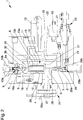
Figure 1 is a sectional view of a valve assembly according to the invention with the command means in neutral position and the activation element in normal operating position; -
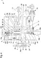
Figure 2 is a sectional view of the valve assembly ofFigure 1 with the command means in neutral position and the activation element in emergency position; -
Figure 3 is a sectional view of the valve assembly ofFigure 1 with the command means in the first work position; -
Figure 4 is a sectional view of the valve assembly ofFigure 1 with the command means in the second work position. - With particular reference to such figures,
reference number 1 globally designates a valve assembly connectable to a trailer comprising a first and a second female joint (not shown in the figures) in turn connectable to a first and to a second male joint (also not shown in the figures) respectively, associated with the towing vehicle. More in detail the first female joint is communicating with a control line, able to receive a work fluid at a first pressure as a result of the connection to the first male joint for the power supply of the braking system of the trailer, and the second female joint is communicating with at least an additional line, able to receive a work fluid at a second pressure as a result of the connection of the second female joint to the second male joint to control the parking and/or automatic brake of the trailer itself, and to at least a bypass line communicating with a discharge line. Valve means are also provided able to put the additional line in communication with the bypass line as a result of the exit of the second male joint from the second female joint. - The
assembly 1 comprises abody 2 inside which are defined: at least acontrol channel 5 connectable to the control line of the trailer, at least abraking channel 6 connectable to the braking line of the trailer, and at least aconnection channel 16 able to put thecontrol channel 5 in communication with thebraking channel 6 and along which are placed first valve means 9 able to permit/prevent the flow of the work fluid along the connection channel itself. More particularly, the first valve means 9 are movable between at least a closed position and at least an open position wherein they prevent and permit, respectively, the flow of the work fluid along theconnection channel 16. - Advantageously, the first valve means 9 comprise at least a first and a
second shutter second passage channel connection channel 16 and intended to be moved in sequence to their respective open positions. Bothshutters passage channel - More particularly, the
first shutter 9a is slidably inserted within thesecond shutter 9b, the latter being hollow and defining thefirst passage channel 16a, moves towards the open position in contrast to firstelastic means 10a and protrudes, in its closed position, from the top of the second shutter itself. Thesecond shutter 9b, in turn, rests, in its closed position, against thebody 2, so that thesecond passage channel 16b is positioned outside of thefirst passage channel 16a. Thesecond shutter 9b moves in contrast to the second elastic means 10b. - Conveniently, the section of the
first passage channel 16a is smaller than that of thesecond passage channel 16b. - In the
body 2 are also defined: at least asupply channel 7 connected to a hydraulic accumulator, between which are interposed second valve means 29 able to put in communication/isolate thesupply channel 7 with/from the accumulator. - More in detail, the second valve means 29 comprise a
shutter 29a movable between a closed configuration and an open configuration, wherein it prevents and allows, respectively, the outflow of the work fluid from the accumulator towards thesupply channel 7, andelastic means 29b able to counteract the displacement of theshutter 29a towards the open configuration. - Moreover, in the
body 2 are also defined at least a connectingchannel 22 able to put thesupply channel 7 in communication with thebraking channel 6, and at least anauxiliary channel 20 able to put thecontrol channel 5 in communication with the accumulator and along which are arranged one-way valve means 21 able to prevent the flow of the work fluid from the accumulator to the control channel itself. - In the
body 2 are further defined at least anadditional channel 11, connectable to the additional line of the trailer, and at least adischarge channel 12, connectable to the discharge line of the trailer. More particularly, theadditional channel 11 is connectable to the additional line of the trailer for the deactivation of the parking and/or automatic brake of the trailer itself and thedischarge channel 12 can be connectable to a tank, of the dynamic type or not, or without further connections. As mentioned above, thedischarge channel 12 is intended to be put in communication with theadditional channel 11, through the bypass channel of the second female joint, as a result of the exit of the second male joint from the relative second female joint. - Conveniently, the
discharge channel 12 is communicating with thecontrol channel 5 and between them is interposed at least a one-way valve 14, which is able to prevent the flow of the work fluid from thecontrol channel 5 towards thedischarge channel 12. - According to the invention, the
valve assembly 1 then comprises at least anactivation element 15 housed in a sliding manner inside aseat 4 defined in thebody 2 and able to interact with the first and second valve means 9 and 29. - The
activation element 15 is then interposed between the first and second valve means 9, 29 and on it act afirst thrust chamber 17, facing to the side of the second valve means 29, and asecond thrust chamber 18, arranged on the opposite side of thefirst thrust chamber 17 with respect to the activation element itself and, consequently, facing to the side of the first valve means 9.Elastic means 19 are also provided able to act on theactivation element 15 towards thefirst thrust chamber 17. In other words, the elastic means 19 push theactivation element 15 in contrast to the force exerted on the same by thefirst thrust chamber 17. Theelastic means 19 are therefore arranged inside thesecond thrust chamber 18. - In the particular embodiment shown in the figures, the thrust areas of the
activation element 15 on which act the first and thesecond thrust chamber - The first and
second thrust chambers additional channel 11 and thedischarge channel 12. - The
valve assembly 1 also comprises asolenoid valve 13, connectable to the power supply of the towing vehicle, and connected to theadditional channel 11, to thedischarge channel 12 and to thethrust chambers - The
solenoid valve 13 is movable between at least an inactive configuration, wherein the first andsecond thrust chambers first thrust chamber 17 is connected to theadditional channel 11 and thesecond thrust chamber 18 is connected to thedischarge channel 12. - In the preferred embodiment shown in the figures, the
second thrust chamber 18 is put in communication with thedischarge channel 12 and thesolenoid valve 13 is interposed between thefirst thrust chamber 17, thesecond thrust chamber 18 and theadditional channel 11. In its active configuration thesolenoid valve 13 puts thefirst thrust chamber 17 in communication with theadditional channel 11 isolating thefirst thrust chamber 17 from thesecond thrust chamber 18, while in its inactive configuration thesolenoid valve 13 puts thefirst thrust chamber 17 in communication with thesecond thrust chamber 18 isolating thefirst thrust chamber 17 from theadditional channel 11. - Alternative embodiments cannot however be ruled out wherein the
first thrust chamber 17 is put in communication with theadditional channel 11 and thesolenoid valve 13 is interposed among thefirst thrust chamber 17, thesecond thrust chamber 18 and thedischarge channel 12, and wherein in its inactive configuration thesolenoid valve 13 puts thesecond thrust chamber 18 in communication with thefirst thrust chamber 17, and therefore with theadditional channel 11, isolating the second thrust chamber from thedischarge channel 12, and an active configuration, wherein thesolenoid valve 13 puts thesecond thrust chamber 18 in communication with thedischarge channel 12, isolating the second thrust chamber from theadditional channel 11. - The
solenoid valve 13 is positioned in the inactive configuration as a result of the decoupling of the trailer from the towing vehicle or if the latter does not send any electrical signal to the trailer itself. Advantageously, between theactivation element 15 and the first valve means 9 is interposed at least afirst interaction element 30, e.g. of the cylinder type. - Similarly, between the
activation element 15 and the second valve means 29 is interposed at least asecond interaction element 31, e.g. of the cylinder type. - Preferably, the
activation element 15 comprises afirst thrust element 15a, e.g. of the glass-shaped type and able to cooperate with thesecond interaction element 31, and asecond thrust element 15b, housed inside thefirst thrust element 15a and able to cooperate with thefirst interaction element 30. Theelastic means 19 are interposed between the first and thesecond thrust elements activation element 15 is movable between at least a normal operating position and an emergency position. The normal operating position corresponds to the condition wherein the male joints are inserted inside the relative female joints, thesolenoid valve 13 is in the active configuration, and wherein theadditional channel 11 is pressurized and isolated from thedischarge channel 12. - In this position, the
activation element 15 moves in contrast to the elastic means 19 due to the pressure in thefirst thrust chamber 17, thesecond thrust chamber 18 being connected to thedischarge channel 12. Thesecond thrust chamber 18 can be released in thecontrol channel 5, by means of the one-way valve 14, in the event of this being at a lower pressure than that in thedischarge channel 12, e.g. as a result of the interruption of the braking in the towing vehicle. - It follows that the
activation element 15, moving towards the normal operating position, interacts with the first valve means 9 so as to open theconnection channel 16 and then connect thecontrol channel 5 to thebraking channel 6. - More in detail, the
activation element 15 interacts in sequence with the first and with thesecond shutter first interaction element 30, thus opening thefirst passage channel 16a and, subsequently, thesecond passage channel 16b. - The
first interaction element 30 is then pushed by theactivation element 15 towards the first valve means 9 so as to move in sequence the first and thesecond shutter - The accumulator is charged when the pressure of the work fluid along the
control channel 5 is higher than that found in the accumulator itself. Anauxiliary channel 20 is communicating on one side with thecontrol channel 5 and on the other side with the accumulator, and along which one-way valve means 21 are arranged able to prevent the flow of the work fluid from the accumulator towards thecontrol channel 5, by means of which one part of the work fluid that flows through the control channel itself is conveyed into the accumulator. Conveniently, apressure switch 23 is also connected to the accumulator. - Advantageously, the
assembly 1 also comprises an electric device (not shown in the figures) operatively connected to the pressure switch, to thesolenoid valve 13 and to the power supply of the towing vehicle and able to maintain thesolenoid valve 13 in the active configuration until the pressure in the accumulator reaches a predefined value. - In the preferred embodiment shown in the figures, the
auxiliary channel 20 is directly put in communication with the accumulator. - Alternative embodiments cannot however be ruled out wherein the
auxiliary channel 20 is put in communication with thesupply channel 7 and the work fluid incoming from the same enters inside the accumulator and seeps through the second valve means 29. - The
activation element 15 then reaches the emergency position as a result of the drop in pressure in the additional channel 11 (e.g. due to the operation of the parking brake of the towing vehicle) or of the connection of the latter with the discharge channel 12 (e.g. due to the exit of the second male joint from the second female joint) or of the displacement of thesolenoid valve 13 to the inactive configuration, the activation element itself is moved by the elastic means 19 towards the second valve means 29 to allow the outflow of the work fluid from the accumulator into thesupply channel 7 and from the latter into thebraking channel 6 through the connectingchannel 22. In this operating condition, in fact, either the pressure in thefirst thrust chamber 17 resets (operation of the parking brake of the towing vehicle) or it is substantially equivalent to that in the second thrust chamber 18 (exit of the second male joint from the second female joint), whereby the only action exerted on theactivation element 15 is that of theelastic means 19. - More in detail, the displacement of the
activation element 15 towards the emergency position causes the displacement of thesecond interaction element 31, which interacts with theshutter 29a of the second valve means 29, moving it to its open position. - In this emergency position, the first valve means 9 are in the closed position, isolating the
control channel 5 from thebraking channel 6. - The work fluid contained in the accumulator then flows out through the
supply channel 7 and supplies the braking system of the trailer by means of thebraking channel 6. - It can be understood that, as a result of the activation of the
solenoid valve 13, thefirst thrust chamber 17 is put in communication with theadditional channel 11 and is isolated from thedischarge channel 12, consequently theactivation element 15 is pushed in contrast to the elastic means 19 moving to the normal operating position. - In the passage from the emergency position to the normal operating position, and vice versa, both the first and the second valve means 9, 29 are in the closed position. More in detail, when the
activation element 15 is arranged against one of the first and thesecond interaction element first interaction element - Advantageously, the
assembly 1 comprises manual command means 24, which are operable to command the displacement of theactivation element 15 to at least a predefined position. The command means 24 are able to be operated as a result of the exit of the male joints from the relative female joints. - More particularly, the command means 24 are movable between a neutral position, wherein the
activation element 15 is free to move between the normal operating position and the emergency position, and at least a first work position, wherein theactivation element 15 is pushed in contrast to the elastic means 19, starting from the emergency position it takes on as a result of the connection between theadditional channel 11 and thedischarge channel 12 following the exit of the male joints from the female joints, and wherein both the first and the second valve means 9 and 29 are in the closed position. - Preferably, the
assembly 1 comprises pumping means 25 positioned along theauxiliary channel 20 and operable, with the command means 24 in the first work position, to aspirate the work fluid in thecontrol channel 5 and send it inside the accumulator. - It is easy to appreciate that the pumping means 25 are also able to aspirate the work fluid along the
additional channel 11 in the event of the latter being put in communication with thedischarge channel 12 as a result of the exit of the second male joint from its second female joint; as mentioned above, in fact, thedischarge channel 12 is communicating with thecontrol channel 5. - Conveniently, the pumping means 25 are of the manual type and are interposed between the one-way valve means 21, which comprise at least two one-way valves able to permit the aspiration of the work fluid from the
control channel 5 and the sending thereof towards the accumulator but not vice versa. - Advantageously, the command means 24 are also movable to a second work position, wherein the
activation element 15 is pushed further in contrast to the elastic means 19 with respect to the first work position causing the opening of the first valve means 9 and, then, putting thecontrol channel 5 in communication with thebraking channel 6. - In this second work position of the command means 24, the pumping means 25 are also operable to aspirate the work fluid along the
braking channel 6, still passing through thecontrol channel 5, and send it inside the accumulator. - In the preferred embodiment shown in the figures, the command means 24 comprise at least an
actuation element 26, of the type of a knob, positioned outside of thebody 2 and movable in rotation with respect to it, wheresuch knob 26 is connected to acam element 27 which interacts with theactivation element 15. - More particularly, the command means 24 also comprise a
safety element 26a associated with theactuation element 26 and connectable to the towing vehicle. In the event of the command means 24 being arranged in the second work position and the trailer detaching from the towing vehicle, thesafety element 26a is displaced so as to move the command means 24 to their neutral position so that theactivation element 15 is pushed by the elastic means 19 to the emergency position causing the first valve means 9 to close and the second valve means 29 to open and the consequent braking of the trailer. This is particularly useful if the towing vehicle is without the line connectable to the additional line of the trailer. Suitably, furtherelastic means 28 are provided associated with the command means 24 and able to exert a torque on them, in contrast to the displacement of the command means themselves from the neutral position towards the aforementioned work positions. - More in detail, the further
elastic means 28 are the type of a pin spring having a first pin (not visible in detail in the figures) locked together with thebody 2 and a second pin (not visible in detail in the figures) locked together with theactuation element 26, the second pin being able to return to the initial position as a result of the rotation of the actuation element itself. - It follows, therefore, that if the operator leaves unintentionally the command means 24 in the first or in the second work position even as a result of the insertion of the male joints inside the relative female joints (and therefore of the activation of the solenoid valve 13), due to the pressure in the
additional channel 11, theactivation element 15 is further moved as far as reaching the end-of-stroke position corresponding to the normal operating position and thus releasing the command means 24 which, due to the action exerted by the furtherelastic means 28, return to their neutral position. - It has in practice been observed how the described invention achieves the intended objects and in particular the fact is underlined that the assembly according to the invention allows to supply the braking system of a trailer under emergency conditions by means of a hydraulic accumulator.
- The valve assembly making the subject of the present invention also allows to release easily the pressure along the various lines of the trailer, i.e. along the control, the additional and the braking lines, so as to allow the subsequent connection of the male joints to the relative female joints.
Claims (15)
- Valve assembly (1), particularly for trailers comprising a first and a second female joint connectable to a first and to a second male joint respectively, associated with the towing vehicle, where the first female joint is communicating with a control line of the braking system of the trailer itself and where the second female joint is communicating with at least an additional line acting on the parking and/or automatic brake of the trailer, the valve assembly comprising at least a bypass line communicating with a discharge line, and valve means able to put the additional line in communication with the bypass line as a result of the exit of the second male joint from the second female joint, characterized by the fact that it comprises:- a body (2) wherein are defined:o at least a control channel (5) connectable to said control line of the trailer;o at least a braking channel (6), connectable to the braking system of the trailer;o at least a connection channel (16) interposed between said control channel (5) and said braking channel (6) and along which are placed first valve means (9) to allow/prevent the flow of the work fluid along the connection channel itself;o at least a supply channel (7) connected to a hydraulic accumulator, second valve means (29) being provided to put in communication/isolate said supply channel (7) with/from said accumulator;o at least a connecting channel (22) to put said supply channel (7) in communication with said braking channel (6);o at least an auxiliary channel (20) to put said control channel (5) in communication with said accumulator and along which are arranged one-way valve means (21) to prevent the flow of fluid from the accumulator towards the control channel itself;o at least an additional channel (11) connectable to said additional line of the trailer;o at least a discharge channel (12) connectable to said discharge line of the trailer;- at least an activation element (15) housed in a sliding manner inside a seat (4) defined in said body (2), interposed between said first and second valve means (9, 29) and on which act, on opposite sides of the same, at least a first thrust chamber (17) facing to the side of said second valve means (29) and a second thrust chamber (18) facing to the side of said first valve means (9), elastic means (19) are also provided able to act on the activation element to push it towards said first thrust chamber (17), said first and second thrust chambers (17, 18) being connectable to at least one of said additional channel (11) and said discharge channel (12);- at least a solenoid valve (13) connectable to the power supply of the towing vehicle and connected to said additional channel (11), to said discharge channel (12) and to said first and second thrust chambers (17, 18), said solenoid valve (13) being movable between at least an inactive configuration, wherein said first and second thrust chambers (17, 18) are communicating with each other, and at least an active configuration, wherein said first thrust chamber (17) is communicating with said additional channel (11) and said second thrust chamber (18) is communicating with said discharge channel (12);- said activation element (15) being movable between at least:o a normal operating position, corresponding to the operating condition wherein said additional channel (11) is pressurized and said solenoid valve (13) is in the active configuration, and wherein the activation element itself moves in contrast to the force exerted by said elastic means (19) and interacts with said first valve means (9) to put said braking channel (6) in communication with said control channel (5), the latter supplying said accumulator by means of said auxiliary channel (20) with said second valve means (29) in the closed position;o and an emergency position, corresponding to the operating condition wherein takes place a drop in pressure in said additional channel (11) or the connection of the latter with said discharge channel (12) as a result of the exit of the second male joint from its second female joint or of the displacement of said solenoid valve (13) to the inactive position, and wherein the activation element itself interacts with said second valve means (29) to allow the outflow of the work fluid from said accumulator to said supply channel (7) and from this to said braking channel (6) through said connecting channel (22), and wherein said first valve means (9) are in the closed position isolating said control channel (5) from said braking channel (6).
- Valve assembly (1) according to claim 1, characterized by the fact that in the passage from the emergency position to the normal operating position of said activation element (15) both the first and the second valve means (9, 29) are in the closed position.
- Valve assembly (1) according to claim 1 or 2, characterized by the fact that it comprises at least a first interaction element (30) interposed between said activation element (15) and said first valve means (9), said activation element (15), in the displacement to the normal operating position, being able to push said first interaction element (30) towards said first valve means (9) to move the latter to the open position.
- Valve assembly (1) according to one or more of the preceding claims, characterized by the fact that it comprises at least a second interaction element (31) interposed between said activation element (15) and said second valve means (29), said activation element (15), in the displacement to the emergency position, being able to push said second interaction element (31) towards the second valve means (29) to move the latter to the open position.
- Valve assembly (1) according to claims 3 and 4, characterized by the fact that when said activation element (15) rests against one of said first and said second interaction elements (30, 31) it is spaced from the other of said second and said first interaction element (31, 30).
- Valve assembly (1) according to one or more of the preceding claims, characterized by the fact that said first valve means (9) comprise at least a first and a second shutter (9a, 9b) able to obstruct a first and a second passage channel (16a, 16b) respectively, of the work fluid along said connection channel (16), said activation element (15) being able to move in sequence said first and second shutter (9a, 9b) to their respective open positions during the displacement thereof towards the normal operating position.
- Valve assembly (1) according to claim 6, characterized by the fact that said first shutter (9a) is slidably inserted within said second shutter (9b), the latter being hollow and defining said first passage channel (16a), and protrudes, in its closed position, from the top of the second shutter itself, said first interaction element (30) being able to contact, in sequence, said first and said second shutter (9a, 9b) during the displacement of the activation element (15) towards the normal operating position.
- Valve assembly (1) according to one or more of the preceding claims 6 and 7, characterized by the fact that said second shutter (9b) rests, in its closed position, against said body (2), said second passage channel (16b) being positioned outside of said first passage channel (16a).
- Valve assembly (1) according to one or more of the preceding claims, characterized by the fact that said activation element (15) comprises a first thrust element (15a), with a glass shape and able to cooperate with said second interaction element (31), and a second thrust element (15b) housed inside said first thrust element (15a) and able to cooperate with said first interaction element (30), said elastic means (19) being interposed between said first and said second thrust element (15a, 15b).
- Valve assembly (1) according to one or more of the preceding claims, characterized by the fact that it comprises manual command means (24) operable to command the displacement of said activation element (15) to at least a predefined position inside said seat (4).
- Valve assembly (1) according to claim 10, characterized by the fact that said command means (24) are movable between a neutral position, wherein said activation element (15) is free to move between said normal operating position and said emergency position, and at least a first work position wherein, starting from the emergency position, said activation element (15) is pushed in contrast to said elastic means (19), and wherein said first and said second valve means (9, 29) are in the closed position.
- Valve assembly (1) according to claim 11, characterized by the fact that it comprises pumping means (25) positioned along said auxiliary channel (20) and operable, with said command means (24) in the first work position, to aspirate the work fluid in said control channel (5) and to send it to said accumulator; said pumping means (25) being also able to aspirate the work fluid in said additional channel (11) in the event of the latter being put in communication with said discharge channel (12) as a result of the exit of the second male joint from its second female joint, said discharge channel (12) being in communication with said control channel (5).
- Valve assembly (1) according to one or more of claims 10 to 12, characterized by the fact that said command means (24) are also movable to a second work position, wherein said activation element (15) is pushed further in contrast to said elastic means (19) with respect to said first work position and said first valve means (9) are in the open position.
- Valve assembly (1) according to claim 13, characterized by the fact that, with said command means (24) in the second work position, said pumping means (25) are operable to aspirate the work fluid along said braking channel (6) by means of said control channel (5) and to send it to said accumulator.
- Valve assembly (1) according to one or more of the preceding claims 10 to 14, characterized by the fact that said command means (24) comprise at least an actuation element (26) positioned outside of said body (2), connected to a cam element (27) interacting with said activation element (15) and operable to move the command means themselves from the neutral position to at least one of said work positions and vice versa.
Applications Claiming Priority (1)
| Application Number | Priority Date | Filing Date | Title |
|---|---|---|---|
| ITMO2015A000087A ITMO20150087A1 (en) | 2015-04-21 | 2015-04-21 | VALVE BLOCK |
Publications (2)
| Publication Number | Publication Date |
|---|---|
| EP3085589A1 EP3085589A1 (en) | 2016-10-26 |
| EP3085589B1 true EP3085589B1 (en) | 2019-06-05 |
Family
ID=53539805
Family Applications (1)
| Application Number | Title | Priority Date | Filing Date |
|---|---|---|---|
| EP16166351.3A Active EP3085589B1 (en) | 2015-04-21 | 2016-04-21 | Valve assembly |
Country Status (2)
| Country | Link |
|---|---|
| EP (1) | EP3085589B1 (en) |
| IT (1) | ITMO20150087A1 (en) |
Family Cites Families (2)
| Publication number | Priority date | Publication date | Assignee | Title |
|---|---|---|---|---|
| DE2243472C3 (en) * | 1969-10-17 | 1978-09-14 | Girling Ltd., Birmingham, West Midlands (Grossbritannien) | Towing vehicle and trailer brake system with a spring-loaded brake as a parking brake in both vehicles |
| FR2897580B1 (en) * | 2006-02-22 | 2008-05-16 | Poclain Hydraulics Ind Soc Par | DEVICE FOR CONTROLLING THE HYDRAULIC BRAKE OF A TRAILER ATTACHED TO A TRACTOR |
-
2015
- 2015-04-21 IT ITMO2015A000087A patent/ITMO20150087A1/en unknown
-
2016
- 2016-04-21 EP EP16166351.3A patent/EP3085589B1/en active Active
Non-Patent Citations (1)
| Title |
|---|
| None * |
Also Published As
| Publication number | Publication date |
|---|---|
| ITMO20150087A1 (en) | 2016-10-21 |
| EP3085589A1 (en) | 2016-10-26 |
Similar Documents
| Publication | Publication Date | Title |
|---|---|---|
| EP3481685B1 (en) | Vehicle braking system | |
| RU2738507C1 (en) | Parking brake valve device | |
| CN107635837B (en) | Pneumatic brake system for a trailer | |
| CN107771141B (en) | Parking brake mechanism for motor vehicle | |
| EA012540B1 (en) | Method for releasing at least one spring-loaded brake actuated by means of a hydraulic fluid, and also a device and a hydraulic circuit for carrying out said method | |
| EP2952398B1 (en) | Valve assembly | |
| EP3294596B1 (en) | Braking device | |
| EP3085589B1 (en) | Valve assembly | |
| EP3085590B1 (en) | Device for controlling the braking of a trailer | |
| EP3368385B1 (en) | Braking device for trailers of agricultural machines | |
| CN108602503B (en) | Parking release valve for trailer | |
| EP3000631B1 (en) | Device for the towing vehicle-trailer connection | |
| EP3225473B1 (en) | Device for the control of the braking of a trailer | |
| EP3000672B1 (en) | Valve assembly for trailer | |
| EP3401176B1 (en) | Device for controlling the braking of a trailer | |
| EP3650293B1 (en) | Device for controlling the braking of a trailer | |
| EP3064408B1 (en) | Device for controlling the braking of a trailer | |
| EP3243715B1 (en) | Hydraulic distributor for braking a towed machine | |
| EP4054907B1 (en) | Device for controlling the braking of a trailer | |
| EP3165385B1 (en) | Device for the towing vehicle-trailer connection | |
| EP3319848B1 (en) | Actuating device of a valve for the braking of a trailer | |
| US20070296267A1 (en) | Apparatus for braking systems of articulated vehicles | |
| EP2955073B1 (en) | Device for the towing vehicle-trailer connection | |
| US20190031167A1 (en) | Brake System for a Motor Vehicle, and Method for Operating the Brake System | |
| EP3611063B1 (en) | Tractor-trailer connection device |
Legal Events
| Date | Code | Title | Description |
|---|---|---|---|
| PUAI | Public reference made under article 153(3) epc to a published international application that has entered the european phase |
Free format text: ORIGINAL CODE: 0009012 |
|
| AK | Designated contracting states |
Kind code of ref document: A1 Designated state(s): AL AT BE BG CH CY CZ DE DK EE ES FI FR GB GR HR HU IE IS IT LI LT LU LV MC MK MT NL NO PL PT RO RS SE SI SK SM TR |
|
| AX | Request for extension of the european patent |
Extension state: BA ME |
|
| 17P | Request for examination filed |
Effective date: 20170426 |
|
| RBV | Designated contracting states (corrected) |
Designated state(s): AL AT BE BG CH CY CZ DE DK EE ES FI FR GB GR HR HU IE IS IT LI LT LU LV MC MK MT NL NO PL PT RO RS SE SI SK SM TR |
|
| STAA | Information on the status of an ep patent application or granted ep patent |
Free format text: STATUS: REQUEST FOR EXAMINATION WAS MADE |
|
| 111Z | Information provided on other rights and legal means of execution |
Free format text: AL AT BE BG CH CY CZ DE DK EE ES FI FR GB GR HR HU IE IS IT LT LU LV MC MK MT NL NO PL PT RO RS SE SI SK SM TR Effective date: 20180208 |
|
| RAP1 | Party data changed (applicant data changed or rights of an application transferred) |
Owner name: SAFIM S.P.A. |
|
| GRAP | Despatch of communication of intention to grant a patent |
Free format text: ORIGINAL CODE: EPIDOSNIGR1 |
|
| STAA | Information on the status of an ep patent application or granted ep patent |
Free format text: STATUS: GRANT OF PATENT IS INTENDED |
|
| INTG | Intention to grant announced |
Effective date: 20181114 |
|
| GRAS | Grant fee paid |
Free format text: ORIGINAL CODE: EPIDOSNIGR3 |
|
| RIN1 | Information on inventor provided before grant (corrected) |
Inventor name: MAMEI, ENRICO Inventor name: MAMEI, ANDREA Inventor name: MAMEI, ERONNE |
|
| GRAA | (expected) grant |
Free format text: ORIGINAL CODE: 0009210 |
|
| STAA | Information on the status of an ep patent application or granted ep patent |
Free format text: STATUS: THE PATENT HAS BEEN GRANTED |
|
| AK | Designated contracting states |
Kind code of ref document: B1 Designated state(s): AL AT BE BG CH CY CZ DE DK EE ES FI FR GB GR HR HU IE IS IT LI LT LU LV MC MK MT NL NO PL PT RO RS SE SI SK SM TR |
|
| REG | Reference to a national code |
Ref country code: GB Ref legal event code: FG4D |
|
| REG | Reference to a national code |
Ref country code: CH Ref legal event code: EP |
|
| REG | Reference to a national code |
Ref country code: AT Ref legal event code: REF Ref document number: 1139676 Country of ref document: AT Kind code of ref document: T Effective date: 20190615 |
|
| REG | Reference to a national code |
Ref country code: DE Ref legal event code: R096 Ref document number: 602016014704 Country of ref document: DE |
|
| REG | Reference to a national code |
Ref country code: IE Ref legal event code: FG4D |
|
| REG | Reference to a national code |
Ref country code: NL Ref legal event code: MP Effective date: 20190605 |
|
| REG | Reference to a national code |
Ref country code: LT Ref legal event code: MG4D |
|
| PG25 | Lapsed in a contracting state [announced via postgrant information from national office to epo] |
Ref country code: FI Free format text: LAPSE BECAUSE OF FAILURE TO SUBMIT A TRANSLATION OF THE DESCRIPTION OR TO PAY THE FEE WITHIN THE PRESCRIBED TIME-LIMIT Effective date: 20190605 Ref country code: AL Free format text: LAPSE BECAUSE OF FAILURE TO SUBMIT A TRANSLATION OF THE DESCRIPTION OR TO PAY THE FEE WITHIN THE PRESCRIBED TIME-LIMIT Effective date: 20190605 Ref country code: HR Free format text: LAPSE BECAUSE OF FAILURE TO SUBMIT A TRANSLATION OF THE DESCRIPTION OR TO PAY THE FEE WITHIN THE PRESCRIBED TIME-LIMIT Effective date: 20190605 Ref country code: NO Free format text: LAPSE BECAUSE OF FAILURE TO SUBMIT A TRANSLATION OF THE DESCRIPTION OR TO PAY THE FEE WITHIN THE PRESCRIBED TIME-LIMIT Effective date: 20190905 Ref country code: SE Free format text: LAPSE BECAUSE OF FAILURE TO SUBMIT A TRANSLATION OF THE DESCRIPTION OR TO PAY THE FEE WITHIN THE PRESCRIBED TIME-LIMIT Effective date: 20190605 Ref country code: ES Free format text: LAPSE BECAUSE OF FAILURE TO SUBMIT A TRANSLATION OF THE DESCRIPTION OR TO PAY THE FEE WITHIN THE PRESCRIBED TIME-LIMIT Effective date: 20190605 Ref country code: LT Free format text: LAPSE BECAUSE OF FAILURE TO SUBMIT A TRANSLATION OF THE DESCRIPTION OR TO PAY THE FEE WITHIN THE PRESCRIBED TIME-LIMIT Effective date: 20190605 |
|
| PG25 | Lapsed in a contracting state [announced via postgrant information from national office to epo] |
Ref country code: LV Free format text: LAPSE BECAUSE OF FAILURE TO SUBMIT A TRANSLATION OF THE DESCRIPTION OR TO PAY THE FEE WITHIN THE PRESCRIBED TIME-LIMIT Effective date: 20190605 Ref country code: BG Free format text: LAPSE BECAUSE OF FAILURE TO SUBMIT A TRANSLATION OF THE DESCRIPTION OR TO PAY THE FEE WITHIN THE PRESCRIBED TIME-LIMIT Effective date: 20190905 Ref country code: RS Free format text: LAPSE BECAUSE OF FAILURE TO SUBMIT A TRANSLATION OF THE DESCRIPTION OR TO PAY THE FEE WITHIN THE PRESCRIBED TIME-LIMIT Effective date: 20190605 Ref country code: GR Free format text: LAPSE BECAUSE OF FAILURE TO SUBMIT A TRANSLATION OF THE DESCRIPTION OR TO PAY THE FEE WITHIN THE PRESCRIBED TIME-LIMIT Effective date: 20190906 |
|
| REG | Reference to a national code |
Ref country code: AT Ref legal event code: MK05 Ref document number: 1139676 Country of ref document: AT Kind code of ref document: T Effective date: 20190605 |
|
| PG25 | Lapsed in a contracting state [announced via postgrant information from national office to epo] |
Ref country code: CZ Free format text: LAPSE BECAUSE OF FAILURE TO SUBMIT A TRANSLATION OF THE DESCRIPTION OR TO PAY THE FEE WITHIN THE PRESCRIBED TIME-LIMIT Effective date: 20190605 Ref country code: PT Free format text: LAPSE BECAUSE OF FAILURE TO SUBMIT A TRANSLATION OF THE DESCRIPTION OR TO PAY THE FEE WITHIN THE PRESCRIBED TIME-LIMIT Effective date: 20191007 Ref country code: SK Free format text: LAPSE BECAUSE OF FAILURE TO SUBMIT A TRANSLATION OF THE DESCRIPTION OR TO PAY THE FEE WITHIN THE PRESCRIBED TIME-LIMIT Effective date: 20190605 Ref country code: AT Free format text: LAPSE BECAUSE OF FAILURE TO SUBMIT A TRANSLATION OF THE DESCRIPTION OR TO PAY THE FEE WITHIN THE PRESCRIBED TIME-LIMIT Effective date: 20190605 Ref country code: EE Free format text: LAPSE BECAUSE OF FAILURE TO SUBMIT A TRANSLATION OF THE DESCRIPTION OR TO PAY THE FEE WITHIN THE PRESCRIBED TIME-LIMIT Effective date: 20190605 Ref country code: RO Free format text: LAPSE BECAUSE OF FAILURE TO SUBMIT A TRANSLATION OF THE DESCRIPTION OR TO PAY THE FEE WITHIN THE PRESCRIBED TIME-LIMIT Effective date: 20190605 Ref country code: NL Free format text: LAPSE BECAUSE OF FAILURE TO SUBMIT A TRANSLATION OF THE DESCRIPTION OR TO PAY THE FEE WITHIN THE PRESCRIBED TIME-LIMIT Effective date: 20190605 |
|
| PG25 | Lapsed in a contracting state [announced via postgrant information from national office to epo] |
Ref country code: SM Free format text: LAPSE BECAUSE OF FAILURE TO SUBMIT A TRANSLATION OF THE DESCRIPTION OR TO PAY THE FEE WITHIN THE PRESCRIBED TIME-LIMIT Effective date: 20190605 Ref country code: IS Free format text: LAPSE BECAUSE OF FAILURE TO SUBMIT A TRANSLATION OF THE DESCRIPTION OR TO PAY THE FEE WITHIN THE PRESCRIBED TIME-LIMIT Effective date: 20191005 |
|
| REG | Reference to a national code |
Ref country code: DE Ref legal event code: R097 Ref document number: 602016014704 Country of ref document: DE |
|
| PG25 | Lapsed in a contracting state [announced via postgrant information from national office to epo] |
Ref country code: TR Free format text: LAPSE BECAUSE OF FAILURE TO SUBMIT A TRANSLATION OF THE DESCRIPTION OR TO PAY THE FEE WITHIN THE PRESCRIBED TIME-LIMIT Effective date: 20190605 |
|
| PLBE | No opposition filed within time limit |
Free format text: ORIGINAL CODE: 0009261 |
|
| STAA | Information on the status of an ep patent application or granted ep patent |
Free format text: STATUS: NO OPPOSITION FILED WITHIN TIME LIMIT |
|
| PG25 | Lapsed in a contracting state [announced via postgrant information from national office to epo] |
Ref country code: PL Free format text: LAPSE BECAUSE OF FAILURE TO SUBMIT A TRANSLATION OF THE DESCRIPTION OR TO PAY THE FEE WITHIN THE PRESCRIBED TIME-LIMIT Effective date: 20190605 Ref country code: DK Free format text: LAPSE BECAUSE OF FAILURE TO SUBMIT A TRANSLATION OF THE DESCRIPTION OR TO PAY THE FEE WITHIN THE PRESCRIBED TIME-LIMIT Effective date: 20190605 |
|
| 26N | No opposition filed |
Effective date: 20200306 |
|
| PG25 | Lapsed in a contracting state [announced via postgrant information from national office to epo] |
Ref country code: SI Free format text: LAPSE BECAUSE OF FAILURE TO SUBMIT A TRANSLATION OF THE DESCRIPTION OR TO PAY THE FEE WITHIN THE PRESCRIBED TIME-LIMIT Effective date: 20190605 |
|
| PG25 | Lapsed in a contracting state [announced via postgrant information from national office to epo] |
Ref country code: MC Free format text: LAPSE BECAUSE OF FAILURE TO SUBMIT A TRANSLATION OF THE DESCRIPTION OR TO PAY THE FEE WITHIN THE PRESCRIBED TIME-LIMIT Effective date: 20190605 |
|
| REG | Reference to a national code |
Ref country code: CH Ref legal event code: PL |
|
| PG25 | Lapsed in a contracting state [announced via postgrant information from national office to epo] |
Ref country code: FR Free format text: LAPSE BECAUSE OF NON-PAYMENT OF DUE FEES Effective date: 20200430 Ref country code: LI Free format text: LAPSE BECAUSE OF NON-PAYMENT OF DUE FEES Effective date: 20200430 Ref country code: CH Free format text: LAPSE BECAUSE OF NON-PAYMENT OF DUE FEES Effective date: 20200430 Ref country code: LU Free format text: LAPSE BECAUSE OF NON-PAYMENT OF DUE FEES Effective date: 20200421 |
|
| REG | Reference to a national code |
Ref country code: BE Ref legal event code: MM Effective date: 20200430 |
|
| PG25 | Lapsed in a contracting state [announced via postgrant information from national office to epo] |
Ref country code: BE Free format text: LAPSE BECAUSE OF NON-PAYMENT OF DUE FEES Effective date: 20200430 |
|
| GBPC | Gb: european patent ceased through non-payment of renewal fee |
Effective date: 20200421 |
|
| PG25 | Lapsed in a contracting state [announced via postgrant information from national office to epo] |
Ref country code: GB Free format text: LAPSE BECAUSE OF NON-PAYMENT OF DUE FEES Effective date: 20200421 Ref country code: IE Free format text: LAPSE BECAUSE OF NON-PAYMENT OF DUE FEES Effective date: 20200421 |
|
| PG25 | Lapsed in a contracting state [announced via postgrant information from national office to epo] |
Ref country code: MT Free format text: LAPSE BECAUSE OF FAILURE TO SUBMIT A TRANSLATION OF THE DESCRIPTION OR TO PAY THE FEE WITHIN THE PRESCRIBED TIME-LIMIT Effective date: 20190605 Ref country code: CY Free format text: LAPSE BECAUSE OF FAILURE TO SUBMIT A TRANSLATION OF THE DESCRIPTION OR TO PAY THE FEE WITHIN THE PRESCRIBED TIME-LIMIT Effective date: 20190605 |
|
| PG25 | Lapsed in a contracting state [announced via postgrant information from national office to epo] |
Ref country code: MK Free format text: LAPSE BECAUSE OF FAILURE TO SUBMIT A TRANSLATION OF THE DESCRIPTION OR TO PAY THE FEE WITHIN THE PRESCRIBED TIME-LIMIT Effective date: 20190605 |
|
| P01 | Opt-out of the competence of the unified patent court (upc) registered |
Effective date: 20230527 |
|
| PGFP | Annual fee paid to national office [announced via postgrant information from national office to epo] |
Ref country code: IT Payment date: 20230419 Year of fee payment: 8 Ref country code: DE Payment date: 20230427 Year of fee payment: 8 |