EP3401163A1 - Lamp for vehicle - Google Patents
Lamp for vehicle Download PDFInfo
- Publication number
- EP3401163A1 EP3401163A1 EP18165581.2A EP18165581A EP3401163A1 EP 3401163 A1 EP3401163 A1 EP 3401163A1 EP 18165581 A EP18165581 A EP 18165581A EP 3401163 A1 EP3401163 A1 EP 3401163A1
- Authority
- EP
- European Patent Office
- Prior art keywords
- light
- region
- vehicle
- controller
- lamp
- Prior art date
- Legal status (The legal status is an assumption and is not a legal conclusion. Google has not performed a legal analysis and makes no representation as to the accuracy of the status listed.)
- Granted
Links
- 230000008859 change Effects 0.000 claims abstract description 49
- 230000000007 visual effect Effects 0.000 claims description 68
- 230000006978 adaptation Effects 0.000 claims description 67
- 230000004313 glare Effects 0.000 claims description 39
- 238000004891 communication Methods 0.000 description 66
- 238000010586 diagram Methods 0.000 description 50
- 238000001514 detection method Methods 0.000 description 47
- 230000005540 biological transmission Effects 0.000 description 21
- 230000003287 optical effect Effects 0.000 description 18
- 238000006243 chemical reaction Methods 0.000 description 15
- 230000004438 eyesight Effects 0.000 description 12
- 230000009467 reduction Effects 0.000 description 12
- 230000004044 response Effects 0.000 description 11
- 238000013459 approach Methods 0.000 description 8
- 210000003128 head Anatomy 0.000 description 8
- 230000001133 acceleration Effects 0.000 description 7
- 230000007423 decrease Effects 0.000 description 7
- 239000000725 suspension Substances 0.000 description 7
- 238000002474 experimental method Methods 0.000 description 6
- 238000005265 energy consumption Methods 0.000 description 5
- 238000012545 processing Methods 0.000 description 5
- 230000003466 anti-cipated effect Effects 0.000 description 4
- 230000006399 behavior Effects 0.000 description 4
- 230000000694 effects Effects 0.000 description 4
- 210000000887 face Anatomy 0.000 description 4
- 230000008921 facial expression Effects 0.000 description 4
- 230000006870 function Effects 0.000 description 4
- 239000010410 layer Substances 0.000 description 4
- 238000012986 modification Methods 0.000 description 4
- 230000004048 modification Effects 0.000 description 4
- 239000004065 semiconductor Substances 0.000 description 4
- OAICVXFJPJFONN-UHFFFAOYSA-N Phosphorus Chemical compound [P] OAICVXFJPJFONN-UHFFFAOYSA-N 0.000 description 3
- 239000004973 liquid crystal related substance Substances 0.000 description 3
- 238000005259 measurement Methods 0.000 description 3
- 230000010363 phase shift Effects 0.000 description 3
- 230000036544 posture Effects 0.000 description 3
- 230000004304 visual acuity Effects 0.000 description 3
- 238000003491 array Methods 0.000 description 2
- 230000004300 dark adaptation Effects 0.000 description 2
- 239000000446 fuel Substances 0.000 description 2
- 230000004301 light adaptation Effects 0.000 description 2
- 238000007726 management method Methods 0.000 description 2
- 238000000034 method Methods 0.000 description 2
- 230000005236 sound signal Effects 0.000 description 2
- 239000010409 thin film Substances 0.000 description 2
- 241001465754 Metazoa Species 0.000 description 1
- XUIMIQQOPSSXEZ-UHFFFAOYSA-N Silicon Chemical compound [Si] XUIMIQQOPSSXEZ-UHFFFAOYSA-N 0.000 description 1
- 230000008901 benefit Effects 0.000 description 1
- 230000000903 blocking effect Effects 0.000 description 1
- 210000004556 brain Anatomy 0.000 description 1
- 238000002485 combustion reaction Methods 0.000 description 1
- 239000000470 constituent Substances 0.000 description 1
- 238000013500 data storage Methods 0.000 description 1
- 230000003247 decreasing effect Effects 0.000 description 1
- 230000002996 emotional effect Effects 0.000 description 1
- 230000007613 environmental effect Effects 0.000 description 1
- 210000003195 fascia Anatomy 0.000 description 1
- 239000002803 fossil fuel Substances 0.000 description 1
- 239000011521 glass Substances 0.000 description 1
- 230000036541 health Effects 0.000 description 1
- BHEPBYXIRTUNPN-UHFFFAOYSA-N hydridophosphorus(.) (triplet) Chemical compound [PH] BHEPBYXIRTUNPN-UHFFFAOYSA-N 0.000 description 1
- 238000007689 inspection Methods 0.000 description 1
- 239000011229 interlayer Substances 0.000 description 1
- 239000002184 metal Substances 0.000 description 1
- 238000012544 monitoring process Methods 0.000 description 1
- 230000007935 neutral effect Effects 0.000 description 1
- 229910052698 phosphorus Inorganic materials 0.000 description 1
- 239000011574 phosphorus Substances 0.000 description 1
- 238000002360 preparation method Methods 0.000 description 1
- 230000002265 prevention Effects 0.000 description 1
- 230000008569 process Effects 0.000 description 1
- 230000035945 sensitivity Effects 0.000 description 1
- 229910052710 silicon Inorganic materials 0.000 description 1
- 239000010703 silicon Substances 0.000 description 1
- 239000007787 solid Substances 0.000 description 1
- 238000006467 substitution reaction Methods 0.000 description 1
- 238000012546 transfer Methods 0.000 description 1
- XLYOFNOQVPJJNP-UHFFFAOYSA-N water Substances O XLYOFNOQVPJJNP-UHFFFAOYSA-N 0.000 description 1
Images


Classifications
-
- B—PERFORMING OPERATIONS; TRANSPORTING
- B60—VEHICLES IN GENERAL
- B60Q—ARRANGEMENT OF SIGNALLING OR LIGHTING DEVICES, THE MOUNTING OR SUPPORTING THEREOF OR CIRCUITS THEREFOR, FOR VEHICLES IN GENERAL
- B60Q1/00—Arrangement of optical signalling or lighting devices, the mounting or supporting thereof or circuits therefor
- B60Q1/02—Arrangement of optical signalling or lighting devices, the mounting or supporting thereof or circuits therefor the devices being primarily intended to illuminate the way ahead or to illuminate other areas of way or environments
- B60Q1/04—Arrangement of optical signalling or lighting devices, the mounting or supporting thereof or circuits therefor the devices being primarily intended to illuminate the way ahead or to illuminate other areas of way or environments the devices being headlights
- B60Q1/14—Arrangement of optical signalling or lighting devices, the mounting or supporting thereof or circuits therefor the devices being primarily intended to illuminate the way ahead or to illuminate other areas of way or environments the devices being headlights having dimming means
- B60Q1/1415—Dimming circuits
- B60Q1/1423—Automatic dimming circuits, i.e. switching between high beam and low beam due to change of ambient light or light level in road traffic
-
- B—PERFORMING OPERATIONS; TRANSPORTING
- B60—VEHICLES IN GENERAL
- B60Q—ARRANGEMENT OF SIGNALLING OR LIGHTING DEVICES, THE MOUNTING OR SUPPORTING THEREOF OR CIRCUITS THEREFOR, FOR VEHICLES IN GENERAL
- B60Q1/00—Arrangement of optical signalling or lighting devices, the mounting or supporting thereof or circuits therefor
- B60Q1/02—Arrangement of optical signalling or lighting devices, the mounting or supporting thereof or circuits therefor the devices being primarily intended to illuminate the way ahead or to illuminate other areas of way or environments
- B60Q1/04—Arrangement of optical signalling or lighting devices, the mounting or supporting thereof or circuits therefor the devices being primarily intended to illuminate the way ahead or to illuminate other areas of way or environments the devices being headlights
- B60Q1/06—Arrangement of optical signalling or lighting devices, the mounting or supporting thereof or circuits therefor the devices being primarily intended to illuminate the way ahead or to illuminate other areas of way or environments the devices being headlights adjustable, e.g. remotely-controlled from inside vehicle
- B60Q1/08—Arrangement of optical signalling or lighting devices, the mounting or supporting thereof or circuits therefor the devices being primarily intended to illuminate the way ahead or to illuminate other areas of way or environments the devices being headlights adjustable, e.g. remotely-controlled from inside vehicle automatically
-
- B—PERFORMING OPERATIONS; TRANSPORTING
- B60—VEHICLES IN GENERAL
- B60Q—ARRANGEMENT OF SIGNALLING OR LIGHTING DEVICES, THE MOUNTING OR SUPPORTING THEREOF OR CIRCUITS THEREFOR, FOR VEHICLES IN GENERAL
- B60Q1/00—Arrangement of optical signalling or lighting devices, the mounting or supporting thereof or circuits therefor
- B60Q1/02—Arrangement of optical signalling or lighting devices, the mounting or supporting thereof or circuits therefor the devices being primarily intended to illuminate the way ahead or to illuminate other areas of way or environments
- B60Q1/04—Arrangement of optical signalling or lighting devices, the mounting or supporting thereof or circuits therefor the devices being primarily intended to illuminate the way ahead or to illuminate other areas of way or environments the devices being headlights
- B60Q1/14—Arrangement of optical signalling or lighting devices, the mounting or supporting thereof or circuits therefor the devices being primarily intended to illuminate the way ahead or to illuminate other areas of way or environments the devices being headlights having dimming means
- B60Q1/1415—Dimming circuits
- B60Q1/1423—Automatic dimming circuits, i.e. switching between high beam and low beam due to change of ambient light or light level in road traffic
- B60Q1/143—Automatic dimming circuits, i.e. switching between high beam and low beam due to change of ambient light or light level in road traffic combined with another condition, e.g. using vehicle recognition from camera images or activation of wipers
-
- B—PERFORMING OPERATIONS; TRANSPORTING
- B60—VEHICLES IN GENERAL
- B60Q—ARRANGEMENT OF SIGNALLING OR LIGHTING DEVICES, THE MOUNTING OR SUPPORTING THEREOF OR CIRCUITS THEREFOR, FOR VEHICLES IN GENERAL
- B60Q1/00—Arrangement of optical signalling or lighting devices, the mounting or supporting thereof or circuits therefor
- B60Q1/26—Arrangement of optical signalling or lighting devices, the mounting or supporting thereof or circuits therefor the devices being primarily intended to indicate the vehicle, or parts thereof, or to give signals, to other traffic
- B60Q1/30—Arrangement of optical signalling or lighting devices, the mounting or supporting thereof or circuits therefor the devices being primarily intended to indicate the vehicle, or parts thereof, or to give signals, to other traffic for indicating rear of vehicle, e.g. by means of reflecting surfaces
-
- B—PERFORMING OPERATIONS; TRANSPORTING
- B60—VEHICLES IN GENERAL
- B60Q—ARRANGEMENT OF SIGNALLING OR LIGHTING DEVICES, THE MOUNTING OR SUPPORTING THEREOF OR CIRCUITS THEREFOR, FOR VEHICLES IN GENERAL
- B60Q1/00—Arrangement of optical signalling or lighting devices, the mounting or supporting thereof or circuits therefor
- B60Q1/26—Arrangement of optical signalling or lighting devices, the mounting or supporting thereof or circuits therefor the devices being primarily intended to indicate the vehicle, or parts thereof, or to give signals, to other traffic
- B60Q1/34—Arrangement of optical signalling or lighting devices, the mounting or supporting thereof or circuits therefor the devices being primarily intended to indicate the vehicle, or parts thereof, or to give signals, to other traffic for indicating change of drive direction
- B60Q1/346—Arrangement of optical signalling or lighting devices, the mounting or supporting thereof or circuits therefor the devices being primarily intended to indicate the vehicle, or parts thereof, or to give signals, to other traffic for indicating change of drive direction with automatic actuation
-
- B—PERFORMING OPERATIONS; TRANSPORTING
- B60—VEHICLES IN GENERAL
- B60Q—ARRANGEMENT OF SIGNALLING OR LIGHTING DEVICES, THE MOUNTING OR SUPPORTING THEREOF OR CIRCUITS THEREFOR, FOR VEHICLES IN GENERAL
- B60Q3/00—Arrangement of lighting devices for vehicle interiors; Lighting devices specially adapted for vehicle interiors
- B60Q3/80—Circuits; Control arrangements
-
- B—PERFORMING OPERATIONS; TRANSPORTING
- B60—VEHICLES IN GENERAL
- B60Q—ARRANGEMENT OF SIGNALLING OR LIGHTING DEVICES, THE MOUNTING OR SUPPORTING THEREOF OR CIRCUITS THEREFOR, FOR VEHICLES IN GENERAL
- B60Q2300/00—Indexing codes for automatically adjustable headlamps or automatically dimmable headlamps
- B60Q2300/05—Special features for controlling or switching of the light beam
- B60Q2300/052—Switching delay, i.e. the beam is not switched or changed instantaneously upon occurrence of a condition change
-
- B—PERFORMING OPERATIONS; TRANSPORTING
- B60—VEHICLES IN GENERAL
- B60Q—ARRANGEMENT OF SIGNALLING OR LIGHTING DEVICES, THE MOUNTING OR SUPPORTING THEREOF OR CIRCUITS THEREFOR, FOR VEHICLES IN GENERAL
- B60Q2300/00—Indexing codes for automatically adjustable headlamps or automatically dimmable headlamps
- B60Q2300/05—Special features for controlling or switching of the light beam
- B60Q2300/054—Variable non-standard intensity, i.e. emission of various beam intensities different from standard intensities, e.g. continuous or stepped transitions of intensity
-
- B—PERFORMING OPERATIONS; TRANSPORTING
- B60—VEHICLES IN GENERAL
- B60Q—ARRANGEMENT OF SIGNALLING OR LIGHTING DEVICES, THE MOUNTING OR SUPPORTING THEREOF OR CIRCUITS THEREFOR, FOR VEHICLES IN GENERAL
- B60Q2300/00—Indexing codes for automatically adjustable headlamps or automatically dimmable headlamps
- B60Q2300/05—Special features for controlling or switching of the light beam
- B60Q2300/056—Special anti-blinding beams, e.g. a standard beam is chopped or moved in order not to blind
-
- B—PERFORMING OPERATIONS; TRANSPORTING
- B60—VEHICLES IN GENERAL
- B60Q—ARRANGEMENT OF SIGNALLING OR LIGHTING DEVICES, THE MOUNTING OR SUPPORTING THEREOF OR CIRCUITS THEREFOR, FOR VEHICLES IN GENERAL
- B60Q2300/00—Indexing codes for automatically adjustable headlamps or automatically dimmable headlamps
- B60Q2300/30—Indexing codes relating to the vehicle environment
- B60Q2300/31—Atmospheric conditions
- B60Q2300/314—Ambient light
-
- B—PERFORMING OPERATIONS; TRANSPORTING
- B60—VEHICLES IN GENERAL
- B60Q—ARRANGEMENT OF SIGNALLING OR LIGHTING DEVICES, THE MOUNTING OR SUPPORTING THEREOF OR CIRCUITS THEREFOR, FOR VEHICLES IN GENERAL
- B60Q2300/00—Indexing codes for automatically adjustable headlamps or automatically dimmable headlamps
- B60Q2300/30—Indexing codes relating to the vehicle environment
- B60Q2300/32—Road surface or travel path
-
- B—PERFORMING OPERATIONS; TRANSPORTING
- B60—VEHICLES IN GENERAL
- B60Q—ARRANGEMENT OF SIGNALLING OR LIGHTING DEVICES, THE MOUNTING OR SUPPORTING THEREOF OR CIRCUITS THEREFOR, FOR VEHICLES IN GENERAL
- B60Q2300/00—Indexing codes for automatically adjustable headlamps or automatically dimmable headlamps
- B60Q2300/30—Indexing codes relating to the vehicle environment
- B60Q2300/33—Driving situation
- B60Q2300/337—Tunnels or bridges
-
- B—PERFORMING OPERATIONS; TRANSPORTING
- B60—VEHICLES IN GENERAL
- B60Q—ARRANGEMENT OF SIGNALLING OR LIGHTING DEVICES, THE MOUNTING OR SUPPORTING THEREOF OR CIRCUITS THEREFOR, FOR VEHICLES IN GENERAL
- B60Q2300/00—Indexing codes for automatically adjustable headlamps or automatically dimmable headlamps
- B60Q2300/40—Indexing codes relating to other road users or special conditions
- B60Q2300/41—Indexing codes relating to other road users or special conditions preceding vehicle
-
- B—PERFORMING OPERATIONS; TRANSPORTING
- B60—VEHICLES IN GENERAL
- B60Q—ARRANGEMENT OF SIGNALLING OR LIGHTING DEVICES, THE MOUNTING OR SUPPORTING THEREOF OR CIRCUITS THEREFOR, FOR VEHICLES IN GENERAL
- B60Q2300/00—Indexing codes for automatically adjustable headlamps or automatically dimmable headlamps
- B60Q2300/40—Indexing codes relating to other road users or special conditions
- B60Q2300/42—Indexing codes relating to other road users or special conditions oncoming vehicle
-
- B—PERFORMING OPERATIONS; TRANSPORTING
- B60—VEHICLES IN GENERAL
- B60Q—ARRANGEMENT OF SIGNALLING OR LIGHTING DEVICES, THE MOUNTING OR SUPPORTING THEREOF OR CIRCUITS THEREFOR, FOR VEHICLES IN GENERAL
- B60Q2300/00—Indexing codes for automatically adjustable headlamps or automatically dimmable headlamps
- B60Q2300/40—Indexing codes relating to other road users or special conditions
- B60Q2300/45—Special conditions, e.g. pedestrians, road signs or potential dangers
-
- B—PERFORMING OPERATIONS; TRANSPORTING
- B60—VEHICLES IN GENERAL
- B60R—VEHICLES, VEHICLE FITTINGS, OR VEHICLE PARTS, NOT OTHERWISE PROVIDED FOR
- B60R11/00—Arrangements for holding or mounting articles, not otherwise provided for
- B60R11/04—Mounting of cameras operative during drive; Arrangement of controls thereof relative to the vehicle
-
- B—PERFORMING OPERATIONS; TRANSPORTING
- B60—VEHICLES IN GENERAL
- B60R—VEHICLES, VEHICLE FITTINGS, OR VEHICLE PARTS, NOT OTHERWISE PROVIDED FOR
- B60R11/00—Arrangements for holding or mounting articles, not otherwise provided for
- B60R2011/0001—Arrangements for holding or mounting articles, not otherwise provided for characterised by position
- B60R2011/0003—Arrangements for holding or mounting articles, not otherwise provided for characterised by position inside the vehicle
-
- F—MECHANICAL ENGINEERING; LIGHTING; HEATING; WEAPONS; BLASTING
- F21—LIGHTING
- F21S—NON-PORTABLE LIGHTING DEVICES; SYSTEMS THEREOF; VEHICLE LIGHTING DEVICES SPECIALLY ADAPTED FOR VEHICLE EXTERIORS
- F21S41/00—Illuminating devices specially adapted for vehicle exteriors, e.g. headlamps
- F21S41/30—Illuminating devices specially adapted for vehicle exteriors, e.g. headlamps characterised by reflectors
- F21S41/32—Optical layout thereof
- F21S41/36—Combinations of two or more separate reflectors
-
- F—MECHANICAL ENGINEERING; LIGHTING; HEATING; WEAPONS; BLASTING
- F21—LIGHTING
- F21S—NON-PORTABLE LIGHTING DEVICES; SYSTEMS THEREOF; VEHICLE LIGHTING DEVICES SPECIALLY ADAPTED FOR VEHICLE EXTERIORS
- F21S41/00—Illuminating devices specially adapted for vehicle exteriors, e.g. headlamps
- F21S41/60—Illuminating devices specially adapted for vehicle exteriors, e.g. headlamps characterised by a variable light distribution
- F21S41/65—Illuminating devices specially adapted for vehicle exteriors, e.g. headlamps characterised by a variable light distribution by acting on light sources
- F21S41/663—Illuminating devices specially adapted for vehicle exteriors, e.g. headlamps characterised by a variable light distribution by acting on light sources by switching light sources
-
- F—MECHANICAL ENGINEERING; LIGHTING; HEATING; WEAPONS; BLASTING
- F21—LIGHTING
- F21S—NON-PORTABLE LIGHTING DEVICES; SYSTEMS THEREOF; VEHICLE LIGHTING DEVICES SPECIALLY ADAPTED FOR VEHICLE EXTERIORS
- F21S41/00—Illuminating devices specially adapted for vehicle exteriors, e.g. headlamps
- F21S41/60—Illuminating devices specially adapted for vehicle exteriors, e.g. headlamps characterised by a variable light distribution
- F21S41/67—Illuminating devices specially adapted for vehicle exteriors, e.g. headlamps characterised by a variable light distribution by acting on reflectors
- F21S41/675—Illuminating devices specially adapted for vehicle exteriors, e.g. headlamps characterised by a variable light distribution by acting on reflectors by moving reflectors
Definitions
- the present invention relates to a lamp for vehicle, and more specifically to a lamp for vehicle which displays a state indicator and an operation indicator on a road surface.
- a vehicle is an apparatus that moves in a direction desired by a user riding therein.
- a representative example of a vehicle may be an automobile.
- ADAS Advanced Driver Assistance System
- a lamp for vehicle may include a head lamp, a rear combination lamp, a turn signal lamp, a room lamp, etc.
- a recently developed lamp for vehicle implements a function of blocking light from being emitted to a region in which a nearby vehicle or a pedestrian is present, so that a driver of the nearby vehicle or the pedestrian is not disturbed by glare.
- the present invention has been made in view of the above problems, and it is one object of the present invention to provide a lamp for vehicle, which prevents reduction in vision acuity of a driver, caused by visual adaptation, and increases or decreases light for a specific region in various conditions.
- a lamp for vehicle including: a lamp module configured to project a light pattern onto a road surface; and a controller configured to, when it is determined, based vehicle driving information, that a light adjustment region exists, perform gradual control of light to gradually change brightness of the light adjustment region.
- the controller may perform the gradual control of light when visual adaptation of a driver is required, and perform On/Off control of light to immediately change light for the light adjustment region when visual adaptation of the driver is not required.
- the controller may determine a first region, a second region, or a third region to be the light adjustment region.
- the first region may be a region which causes glare disturbing a human's eyes
- the second region may be a region whose illuminance is greater than needed
- the third region may be a region where more light is needed.
- the embodiments of the present invention have one or more effects as follows.
- a vehicle as described in this specification may include an automobile and a motorcycle.
- a description will be given based on an automobile.
- a vehicle as described in this specification may include all of an internal combustion engine vehicle including an engine as a power source, a hybrid vehicle including both an engine and an electric motor as a power source, and an electric vehicle including an electric motor as a power source.
- the left side of the vehicle refers to the left side in the forward direction of travel of the vehicle
- the right side of the vehicle refers to the right side in the forward direction of travel of the vehicle
- FIGS. 1 to 7 are diagrams illustrating a vehicle according to the present invention. Hereinafter, a vehicle according to the present invention will be described with reference to FIGS. 1 to 7 .
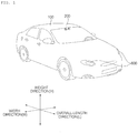
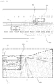
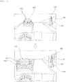
- FIG. 1 is a diagram of the external appearance of a vehicle according to an embodiment of the present invention.
- FIG. 2 is different angled views of a vehicle according to an embodiment of the present invention.
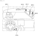
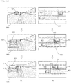
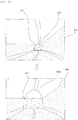
- FIGS. 3 and 4 are diagrams of the internal configuration of a vehicle according to an embodiment of the present invention.
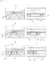
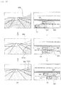
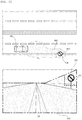
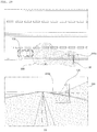
- FIGS. 5 and 6 are diagrams for explanation of objects according to an embodiment of the present invention.
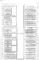
- FIG. 7 is a block diagram illustrating a vehicle according to an embodiment of the present invention.
- a vehicle 100 may include a plurality of wheels, which are rotated by a power source, and a steering input device 510 for controlling a direction of travel of the vehicle 100.
- the vehicle 100 may include various driver assistant apparatuses.
- a driver assistant apparatus is a device that assists a driver based on information acquired from various sensors.
- the driver assistant apparatus may be referred to as an Advanced Driver Assistance System (ADAS).
- ADAS Advanced Driver Assistance System
- the vehicle 100 may include various lighting devices for vehicle.
- a lighting device for vehicle may include a head lamp, a brake lamp, a tail lamp, a turn signal lamp, a room lamp, etc.
- the lighting device for vehicle will be described mainly about a head lamp.
- aspects of the present invention is not limited thereto, and the lighting device for vehicle may be a rear combination lamp.
- the rear combination lamp includes a brake lamp and a trail lamp.
- the vehicle 100 may include a sensing device inside the vehicle 100, and a sensing device outside the vehicle 100.
- overall length means the length from the front end to the rear end of the vehicle 100
- the term “overall width” means the width of the vehicle 100
- the term “overall height” means the height from the bottom of the wheel to the roof.
- the term “overall length direction L” may mean the reference direction for the measurement of the overall length of the vehicle 100
- the term “overall width direction W” may mean the reference direction for the measurement of the overall width of the vehicle 100
- the term “overall height direction H” may mean the reference direction for the measurement of the overall height of the vehicle 100.
- the vehicle 100 may be an autonomous vehicle.
- the vehicle 100 may travel autonomously under the control of the controller 170.
- the vehicle 100 may travel autonomously based on vehicle driving information.
- the vehicle driving information may be information that is acquired by various units in the vehicle 100 during travelling of the vehicle 100.
- the vehicle driving information may be information used for controlling by the controller 170 or an operation system 700 to control the vehicle 100.
- the vehicle driving information may include at least one of the following: object information acquired by an object detection apparatus 300, information received by a communication apparatus 400, and a user input received by a user interface apparatus 200 or a driving manipulation apparatus 500.
- the object information may be information on the form, location, size, and color of a object sensed by the object detection apparatus 300.
- the object information may be information on a lane, an obstacle, a nearby vehicle, a pedestrian, a traffic light, a road structure, content of a traffic sign plate, etc.
- the information received by the communication apparatus 400 may be information transmitted and received by a device capable of performing communication.
- the information received by the communication apparatus 400 may include at least one of the following: information transmitted by a nearby vehicle; information transmitted by a mobile terminal; information transmitted by a traffic infrastructure, and information existing in a specific network.
- the traffic infrastructure may include a traffic light, and the traffic light may transmit information about a traffic signal.
- the vehicle driving information may include at least one of the following: navigation information; information on a control state of the vehicle 100; and location information of the vehicle 100.
- the vehicle driving information may include: information on a nearby vehicle, which is transmitted by the nearby vehicle; information on a travel route; and map information.
- the controller 170 may determine: a type, location, and movement of an object in the vicinity of the vehicle 100; whether a line exists in the vicinity of the vehicle 100; whether a stopping area exists in the vicinity of the vehicle 100; a probability of collision between the vehicle 100 and an object; a distribution of pedestrians or bicycles in the vicinity of the vehicle 100; a type of a road in which the vehicle 100 is travelling; a state of a traffic light in the vicinity of the vehicle 100; and movement of the vehicle 100.
- Vehicle driving information may be acquired by at least one of the user interface apparatus 200, the object detection apparatus 300, the communication apparatus 400, the driving manipulation apparats 500, the navigation system 770, a sensing unit 120, an interface unit 130, and a memory 140, The vehicle driving information, and may provide acquired information to the controller 170. Based on the vehicle driving information, the controller 170 may control the vehicle 100 to travel autonomously.
- a control mode of the vehicle 100 may indicate a subject which controls the vehicle 100.
- a control mode of the vehicle 100 may include: an autonomous mode in which the controller 170 or the operation system 700 included in the vehicle 100 controls the vehicle 100; a manual mode in which a driver in the vehicle 100 controls the vehicle 100; and a remote control mode in which a device other than the vehicle 100 controls the vehicle 100.
- the controller 170 or the operation system 700 may control the vehicle 100 based on vehicle driving information. Accordingly, the vehicle 100 may travel without a user command received via the driving manipulation apparatus 500. For example, when the vehicle 100 is in the autonomous vehicle, the vehicle 100 may travel based on information, data, or a signal generated by a driving system 710, a parking-out system 710, and a parking system 750.
- the vehicle 100 When the vehicle 100 is in the manual mode, the vehicle 100 may be controlled based on a user command for at least one of steering, acceleration, and deceleration, which is received via the driving manipulation apparatus 500.
- the driving manipulation apparatus 500 may generate an input signal corresponding to a user command, and provide the input signal to the controller 170.
- the controller 170 may control the vehicle 100 based on the input signal provided from the driving manipulation apparatus 500.
- a device other than the vehicle 100 may control the vehicle 100.
- the vehicle 100 may receive a remote control signal transmitted by another device via the communication apparatus 400.
- the vehicle 100 may be controlled based on a remote control signal.
- the vehicle 100 may enter one of the autonomous mode, the manual mode, and the remote control mode based on a user input received via the user interface apparatus 200.
- a control mode of the vehicle 100 may be switched to one of the autonomous mode, the manual mode, and the remote control mode based on at least one of occupant information, vehicle driving information, and vehicle state information.
- a control mode of the vehicle 100 may be switched from the manual mode to the autonomous mode, or vice versa, based on object information generated by the object detection apparatus 300.
- a control mode of the vehicle 100 may be switched from the manual mode to the autonomous mode, or vice versa, based on information received via the communication apparatus 400.
- Occupant information may include an image of a user acquired using an internal camera 220 or biometric information sensed using a biometric sensor 230.
- occupant information may be an image of an occupant acquired using the internal camera 220.
- biometric information may be information on temperature, pulse, and brainwaves acquired using the biometric sensing unit 230.
- the controller 170 may determine the location, shape, gaze, face, behavior, facial expression, dozing, health condition, and emotional state of an occupant.
- the occupant information may be acquired using the occupant sensing unit 240, and provide the occupant information to the controller 170.
- Vehicle state information may be information on state of various units provided in the vehicle 100.
- the vehicle state information may include information on a operational state of the user interface apparatus 200, the object detection apparatus 300, the communication apparatus 400, the driving manipulation apparatus 500, a vehicle drive apparatus 600, and an operation system 700, and may include information on whether there is an error in each unit.
- the controller 170 may determine, based on vehicle state information, whether a GPS signal of the vehicle 100 is normally received, whether there is an error in at least one sensor provided in the vehicle 100, or whether each device provided in the vehicle 100 operates properly.
- the vehicle 100 may include the user interface apparatus 200, the objection detection apparatus 300, the communication apparatus 400, the manipulation apparatus 500, a vehicle drive apparatus 600, the operation system 700, a navigation system 770, a sensing unit 120, an interface 130, a memory 140, a controller 170, and a power supply unit 190.
- the vehicle 100 may further include another component in addition to the aforementioned components, or may not include some of the aforementioned components.
- the user interface apparatus 200 is provided to support communication between the vehicle 100 and a user.
- the user interface apparatus 200 may receive a user input, and provide information generated in the vehicle 100 to the user.
- the vehicle 100 may enable User Interfaces (UI) or User Experience (UX) through the user interface apparatus 200.
- UI User Interfaces
- UX User Experience
- the user interface apparatus 200 may include an input unit 210, an internal camera 220, a biometric sensing unit 230, an output unit 250, and an interface processor 270.
- the user interface apparatus 200 may further include other components in addition to the aforementioned components, or may not include some of the aforementioned components.
- the input unit 210 is configured to receive a user command from a user, and data collected by the input unit 210 may be analyzed by the interface processor 270 and then recognized as a control command of the user.
- the input unit 210 may be disposed inside the vehicle 100.
- the input unit 210 may be disposed in a region of a steering wheel, a region of an instrument panel, a region of a seat, a region of each pillar, a region of a door, a region of a center console, a region of a head lining, a region of a sun visor, a region of a windshield, or a region of a window.
- the input unit 210 may include a voice input unit 211, a gesture input unit 212, a touch input unit 213, and a mechanical input unit 214.
- the voice input unit 211 may convert a voice input of a user into an electrical signal.
- the converted electrical signal may be provided to the interface processor 270 or the controller 170.
- the voice input unit 211 may include one or more microphones.
- the gesture input unit 212 may convert a gesture input of a user into an electrical signal.
- the converted electrical signal may be provided to the interface processor 270 or the controller 170.
- the gesture input unit 212 may include at least one selected from among an infrared sensor and an image sensor for sensing a gesture input of a user.
- the gesture input unit 212 may sense a three-dimensional (3D) gesture input of a user.
- the gesture input unit 212 may include a plurality of light emitting units for emitting infrared light, or a plurality of image sensors.
- the gesture input unit 212 may sense the 3D gesture input by employing a Time of Flight (TOF) scheme, a structured light scheme, or a disparity scheme.
- TOF Time of Flight
- the touch input unit 213 may convert a user's touch input into an electrical signal.
- the converted electrical signal may be provided to the interface processor 270 or the controller 170.
- the touch input unit 213 may include a touch sensor for sensing a touch input of a user.
- the touch input unit 210 may be formed integral with a display unit 251 to implement a touch screen.
- the touch screen may provide an input interface and an output interface between the vehicle 100 and the user.
- the mechanical input unit 214 may include at least one selected from among a button, a dome switch, a jog wheel, and a jog switch. An electrical signal generated by the mechanical input unit 214 may be provided to the interface processor 270 or the controller 170.
- the mechanical input unit 214 may be located on a steering wheel, a center fascia, a center console, a cockpit module, a door, etc.
- the occupant sensing unit 240 may sense an occupant inside the vehicle 100.
- the occupant sensing unit 240 may include an internal camera 220 and a biometric sensing unit 230.
- the internal camera 220 may acquire images of the inside of the vehicle 100.
- the processor 270 may sense a state of a user based on the images of the inside of the vehicle 100. For example, a sensed state of a user may be about a user's eye gaze, face, behavior, facial expression, and location.
- the interface processor 270 may determine the user's eye gaze, face, behavior, facial expression, and location.
- the interface processor 270 may determine the user's gesture based on an image of the inside of the vehicle 100.
- the determination made by the interface processor 270 based on the image of the inside of the vehicle 100 may be referred to as occupant information.
- the occupant information is information indicating a user's eye gaze direction, behavior, facial expression, and gesture.
- the interface processor 270 may provide the occupant information to the controller 170.
- the biometric sensing unit 230 may acquire biometric information of the user.
- the biometric sensing unit 230 may include a sensor for acquire biometric information of the user, and may utilize the sensor to acquire the user's finger print information, heart rate information, brain wave information, etc.
- the biometric information may be used to authorize the user or to determine the user's state.
- the interface processor 270 may determine a user's state based on a user's biometric information acquired by the biometric sensing unit 230.
- the user's state determined by the interface processor 270 may be referred to as occupant information.
- the occupant information is information indicating whether the user is in faint, dozing off, excited, or in an emergency situation.
- the interface processor 270 may provide the occupant information to the controller 170.
- the output unit 250 is configured to generate a visual, audio, or tactile output.
- the output unit 250 may include at least one selected from among a display unit 251, a sound output unit 252, and a haptic output unit 253.
- the display unit 251 may display graphic objects corresponding to various types of information.
- the display unit 251 may include at least one selected from among a Liquid Crystal Display (LCD), a Thin Film Transistor-Liquid Crystal Display (TFT LCD), an Organic Light-Emitting Diode (OLED), a flexible display, a 3D display, and an e-ink display.
- LCD Liquid Crystal Display
- TFT LCD Thin Film Transistor-Liquid Crystal Display
- OLED Organic Light-Emitting Diode
- the display unit 251 may form an inter-layer structure together with the touch input unit 213, or may be integrally formed with the touch input unit 213 to implement a touch screen.
- the display unit 251 may be implemented as a Head Up Display (HUD). When implemented as a HUD, the display unit 251 may include a projector module in order to output information through an image projected on a windshield or a window.
- HUD Head Up Display
- the display unit 251 may include a transparent display.
- the transparent display may be attached on the windshield or the window.
- the transparent display may display a predetermined screen with a predetermined transparency.
- the transparent display may include at least one selected from among a transparent Thin Film Electroluminescent (TFEL) display, an Organic Light Emitting Diode (OLED) display, a transparent Liquid Crystal Display (LCD), a transmissive transparent display, and a transparent Light Emitting Diode (LED) display.
- TFEL Thin Film Electroluminescent
- OLED Organic Light Emitting Diode
- LCD transparent Liquid Crystal Display
- LED transparent Light Emitting Diode
- the transparency of the transparent display may be adjustable.
- the user interface apparatus 200 may include a plurality of display units 251a to 251g.
- the display unit 251 may be disposed in a region of a steering wheel, a region 251a, 251b, or 251 e of an instrument panel, a region 251d of a seat, a region 251 f of each pillar, a region 251g of a door, a region of a center console, a region of a head lining, a region of a sun visor, a region 251c of a windshield, or a region 251h of a window.
- the sound output unit 252 converts an electrical signal from the interface processor 270 or the controller 170 into an audio signal, and outputs the audio signal. To this end, the sound output unit 252 may include one or more speakers.
- the haptic output unit 253 generates a tactile output.
- the tactile output is vibration.
- the haptic output unit 253 vibrates a steering wheel, a safety belt, and seats 110FL, 110FR, 110RL, and 110RR so as to allow a user to recognize the output.
- the interface processor 270 may control the overall operation of each unit of the user interface apparatus 200.
- the user interface apparatus 200 may include a plurality of interface processors 270 or may not include the interface processor 270.
- the user interface apparatus 200 may operate under control of the controller 170 or a processor of a different device inside the vehicle 100.
- the user interface apparatus 200 may be referred to as a multimedia device for vehicle.
- the user interface apparatus 200 may operate under control of the controller 170.
- the objection detection apparatus 300 is configured to detect an object outside the vehicle 100.
- the object may include various objects related to travelling of the vehicle 100.
- an object o may include a lane OB10, a line distinguishing the lane OB10, a nearby vehicle OB11, a pedestrian OB12, a two-wheeled vehicle OB13, a traffic signal OB14 and OB15, a curb for distinguishing a sidewalk a light, a road, a structure, a bump, a geographical feature, an animal, etc.
- the lane OB10 may be a driving lane in which the vehicle 100 is traveling, a lane next to the driving lane, and a lane in which an opposing vehicle is travelling.
- the lane OB10 may include left and right lines that define the lane.
- the nearby vehicle OB 11 may be a vehicle that is travelling in the vicinity of the vehicle 100.
- the nearby vehicle OB 11 may be a vehicle located within a predetermined distance from the vehicle 100.
- the nearby vehicle OB11 may be a vehicle that is preceding or following the vehicle 100.
- the nearby vehicle OB11 may be a vehicle travelling on a lane next to a lane in which the vehicle 100 is travelling.
- the pedestrian OB 12 may be a person in the vicinity of the vehicle 100.
- the pedestrian OB12 may be a person located within a predetermined distance from the vehicle 100.
- the pedestrian OB12 may be a person on a sidewalk or on the roadway.
- the two-wheeled vehicle OB13 is a vehicle that is in the vicinity of the vehicle 100 and moves using two wheels.
- the two-wheeled vehicle OB13 may be a vehicle that has two wheels located within a predetermined distance from the vehicle 100.
- the two-wheeled vehicle OB 13 may be a motorcycle or a bike on a sidewalk or the roadway.
- the traffic signal OB14 and OB15 may include a traffic light OB15, a traffic sign plate OB14, and a pattern or text painted on a road surface.
- the light may be light generated by a lamp provided in the nearby vehicle OB 11.
- the light may be light generated by a street light.
- the light may be solar light.
- the road may include a road surface, a curve, and slopes, such as an upward slope and a downward slope.
- the geographical feature may include a mountain, a hill, etc.
- the structure may be a body located around the road in the state of being fixed onto the ground.
- the structure may include a streetlight, a roadside tree, a building, a traffic light, a bridge, a curb, a guardrail, etc.
- the object may be classified as a movable object or a stationary object.
- the movable object is an object which is capable of moving.
- the movable object may be a concept including a nearby vehicle and a pedestrian.
- the stationary object is an object which is incapable of moving.
- the stationary object may be a concept including a traffic signal, a road, a structure, and a line.
- the object detection apparatus 200 may detect an obstacle located outside the vehicle 100.
- the obstacle may be an object, a puddle on the road, an uphill start point, a downhill start point, an inspection pit, a bump, and a curb.
- the object may be an object having a volume and a mass.
- the objection detection apparatus 300 may include a camera 310, a Radio Detection and Ranging (RADAR) 320, a Light Detection and Ranging (LIDAR) 330, an ultrasonic sensor 340, an infrared sensor 350, and a detection processor 370.
- RADAR Radio Detection and Ranging
- LIDAR Light Detection and Ranging
- the objection detection apparatus 300 may further include other components in addition to the aforementioned components, or may not include some of the aforementioned components.
- the camera 310 may be located at an appropriate position outside the vehicle 100 in order to acquire images of the outside of the vehicle 100.
- the camera 310 may provide an acquired image to the detection processor 370.
- the camera 310 may be a mono camera, a stereo camera 310a, an Around View Monitoring (AVM) camera 310b, or a 360-degree camera.
- AVM Around View Monitoring
- the camera 310 may be disposed near a front windshield in the vehicle 100 in order to acquire images of the front of the vehicle 100.
- the camera 310 may be disposed around a front bumper or a radiator grill.
- the camera 310 may be disposed near a rear glass in the vehicle 100 in order to acquire images of the rear of the vehicle 100.
- the camera 310 may be disposed around a rear bumper, a trunk, or a tailgate.
- the camera 310 may be disposed near at least one of the side windows in the vehicle 100 in order to acquire images of the side of the vehicle 100.
- the camera 310 may be disposed around a side mirror, a fender, or a door.
- the RADAR 320 may include an electromagnetic wave transmission unit and an electromagnetic wave reception unit.
- the RADAR 320 may be realized as a pulse RADAR or a continuous wave RADAR depending on the principle of emission of an electronic wave.
- the RADAR 320 may be realized as a Frequency Modulated Continuous Wave (FMCW) type RADAR or a Frequency Shift Keying (FSK) type RADAR depending on the waveform of a signal.
- FMCW Frequency Modulated Continuous Wave
- FSK Frequency Shift Keying
- the RADAR 320 may detect an object through the medium of an electromagnetic wave by employing a time of flight (TOF) scheme or a phase-shift scheme, and may detect a location of the detected object, the distance to the detected object, and the speed relative to the detected object.
- TOF time of flight
- the RADAR 320 may be located at an appropriate position outside the vehicle 100 in order to sense an object located in front of the vehicle 100, an object located to the rear of the vehicle 100, or an object located to the side of the vehicle 100.
- the LIDAR 330 may include a laser transmission unit and a laser reception unit.
- the LIDAR 330 may be implemented by the TOF scheme or the phase-shift scheme.
- the LIDAR 330 may be implemented as a drive type LIDAR or a non-drive type LIDAR.
- the LIDAR 300 may rotate by a motor and detect an object in the vicinity of the vehicle 100.
- the LIDAR 300 may utilize a light steering technique to detect an object located within a predetermined distance from the vehicle 100.
- the LIDAR 330 may detect an object through the medium of laser light by employing the TOF scheme or the phase-shift scheme, and may detect a location of the detected object, the distance to the detected object, and the speed relative to the detected obj ect.
- the LIDAR 330 may be located at an appropriate position outside the vehicle 100 to sense an object located in front of the vehicle 100, an object located to the rear of the vehicle 100, or an object located to the side of the vehicle 100.
- the ultrasonic sensor 340 may include an ultrasonic wave transmission unit and an ultrasonic wave reception unit.
- the ultrasonic sensor 340 may detect an object based on an ultrasonic wave, and may detect a location of the detected object, the distance to the detected object, and the speed relative to the detected object.
- the ultrasonic sensor 340 may be located at an appropriate position outside the vehicle 100 to detect an object located in front of the vehicle 100, an object located to the rear of the vehicle 100, and an object located to the side of the vehicle 100.
- the infrared sensor 350 may include an infrared light transmission unit and an infrared light reception unit.
- the infrared sensor 340 may detect an object based on infrared light, and may detect a location of the detected object, the distance to the detected object, and the speed relative to the detected object.
- the infrared sensor 350 may be located at an appropriate position outside the vehicle 100 to sense an object located in front of the vehicle 100, an object located to the rear of the vehicle 100, or an object located to the side of the vehicle 100.
- the detection processor 370 may control the overall operation of each unit included in the objection detection apparatus 300.
- the detection processor 370 may detect and track an object based on acquired images. Using an image processing algorithm, the detection processor 370 may: calculate the distance to the object and the speed relative to the object; determine an object's type, location, shape, color, and expected route; and determine content of a detected text.
- the detection processor 370 may detect and track an object based RADAR, Radio Detection and Ranging which is formed as the result of reflection a transmission electromagnetic wave by the object. Based on the electromagnetic wave, the detection processor 370 may, for example, calculate the distance to the object and the speed relative to the object.
- the detection processor 370 may detect and track an object based on a reflection laser light which is formed as the result of reflection of transmission laser by the object. Based on the laser light, the detection processor 370 may, for example, calculate the distance to the object and the speed relative to the object.
- the detection processor 370 may detect and track an object based on a reflection ultrasonic wave which is formed as the result of reflection of a transmission ultrasonic wave by the object. Based on the ultrasonic wave, the detection processor 370 may, for example, calculate the distance to the object and the speed relative to the object.
- the detection processor 370 may detect and track an object based on reflection infrared light which is formed as the result of reflection of transmission infrared light by the object. Based on the infrared light, the detection processor 370 may, for example, calculate the distance to the object and the speed relative to the object.
- the detection processor 370 may generate object information based on at least one of the following: an image acquired using the camera 310, a reflected electromagnetic wave received using the RADAR 320, a reflected laser beam received using the LIDAR 330, a reflected ultrasonic wave received using the ultrasonic sensor 340, and a reflected infrared light received using the infrared sensor 350.
- Object information may be information on a type, a location, a size, a shape, a color, a route, and a speed of an object in the vicinity of the vehicle 100, and content of a detected text.
- the object information may indicate the following: whether there is a lane in the vicinity of the vehicle 100; whether nearby vehicles are travelling at a time when the vehicle 100 is in a stop; whether there is a space available to park in the vicinity of the vehicle 100; a probability that the vehicle 100 collides with an object; a location of any pedestrian or bicycle in the vicinity of the vehicle 100; a type of the roadway on which the vehicle 100 is travelling; the current traffic signal indicated by a traffic light in the vicinity of the vehicle 100; and movement of the vehicle.
- the object information may be included in vehicle driving information.
- the detection processor 370 may provide generated object information to the controller 170.
- the objection detection apparatus 300 may include a plurality of detection processors 370 or may not include the processor 370.
- each of the camera 310, the RADAR 320, the LIDAR 330, the ultrasonic sensor 340, and the infrared sensor 350 may include an individual processor.
- the objection detection apparatus 300 may operate under control of the controller 170 or a processor inside the vehicle 100.
- the communication apparatus 400 is configured to perform communication with an external device.
- the external device may be one of a nearby vehicle, a mobile terminal, and a server.
- the communication apparatus 400 may include at least one selected from among a transmission antenna, a reception antenna, a Radio Frequency (RF) circuit capable of implementing various communication protocols, and an RF device.
- RF Radio Frequency
- the communication apparatus 400 may include a short-range communication unit 410, a location information unit 420, a V2X communication unit 430, an optical communication unit 440, a broadcast transmission and reception unit 450, an Intelligent Transport Systems (ITS) communication unit 460, and a communication processor 470.
- a short-range communication unit 410 may include a short-range communication unit 410, a location information unit 420, a V2X communication unit 430, an optical communication unit 440, a broadcast transmission and reception unit 450, an Intelligent Transport Systems (ITS) communication unit 460, and a communication processor 470.
- ITS Intelligent Transport Systems
- the communication apparatus 400 may further include other components in addition to the aforementioned components, or may not include some of the aforementioned components.
- the short-range communication unit 410 is configured to perform short-range communication.
- the short-range communication unit 410 may support short-range communication using at least one selected from among BluetoothTM, Radio Frequency IDdentification (RFID), Infrared Data Association (IrDA), Ultra-WideBand (UWB), ZigBee, Near Field Communication (NFC), Wireless-Fidelity (Wi-Fi), Wi-Fi Direct, and Wireless USB (Wireless Universal Serial Bus).
- RFID Radio Frequency IDdentification
- IrDA Infrared Data Association
- UWB Ultra-WideBand
- ZigBee Near Field Communication
- NFC Near Field Communication
- Wi-Fi Wireless-Fidelity
- Wi-Fi Direct Wireless USB (Wireless Universal Serial Bus).
- the short-range communication unit 410 may form wireless area networks to perform short-range communication between the vehicle 100 and at least one external device.
- the location information unit 420 is configured to acquire location information of the vehicle 100.
- the location information unit 420 may include at least one of a Global Positioning System (GPS) module, a Differential Global Positioning System (DGPS) module, and a Carrier phase Differential GPS (CDGPS) module.
- GPS Global Positioning System
- DGPS Differential Global Positioning System
- CDGPS Carrier phase Differential GPS
- the location information unit 420 may acquire GPS information using a GPS module.
- the location information unit 420 may transfer the acquired GPS information to the controller 170 or the communication processor 470.
- the GPS information acquired by the location information unit 420 may be used for autonomous travelling of the vehicle 100. For example, based on GPS information and navigation information acquired using the navigation system 770, the controller 170 may control the vehicle 100 to travel autonomously.
- the V2X communication unit 430 is configured to perform wireless communication between a vehicle and a server (that is, vehicle to infra (V2I) communication), wireless communication between a vehicle and a nearby vehicle (that is, vehicle to vehicle (V2V) communication), or wireless communication between a vehicle and a pedestrian (that is, vehicle to pedestrian(V2P) communication).
- the V2X communication unit 430 may include a radio frequency (RF) circuit that is capable of implementing protocols for the V2I communication, the V2V communication, and V2P communication.
- RF radio frequency
- the optical communication unit 440 is configured to perform communication with an external device through the medium of light.
- the optical communication unit 440 may include a light emitting unit, which converts an electrical signal into an optical signal and transmits the optical signal to the outside, and a light receiving unit which converts a received optical signal into an electrical signal.
- the light emitting unit may be integrally formed with a lamp provided included in the vehicle 100.
- the broadcast transmission and reception unit 450 is configured to receive a broadcast signal from an external broadcasting management server or transmit a broadcast signal to the broadcasting management server through a broadcasting channel.
- the broadcasting channel may include a satellite channel, and a terrestrial channel.
- the broadcast signal may include a TV broadcast signal, a radio broadcast signal, and a data broadcast signal.
- the ITS communication unit 460 performs communication with a server that provides an intelligent traffic system.
- the ITS communication unit 460 may receive information on various traffic situations from the server of the intelligence traffic system.
- Information on a traffic situation may include a level of traffic congestion, a traffic situation on each road, and an amount of traffics in each area.
- the communication processor 470 may control the overall operation of each unit of the communication apparatus 400.
- Vehicle driving information may include information received using at least one of the short-range communication unit 410, the location information unit 420, the V2X communication unit 430, the optical communication unit 440, and the broadcast transmission and reception unit 450.
- vehicle driving information may include information received from a nearby vehicle, the information which is about a location, a model, route, speed, various sensed values, etc. of a nearby vehicle.
- the controller 170 may acquire information on various objects in the vicinity of the vehicle 100, even through the vehicle 100 does not include an additional sensor.
- the vehicle driving information may indicate the following: a type, location, and movement of an object in the vicinity of the vehicle 100; whether nearby vehicles are travelling at a time when the vehicle 100 is in a stop; whether there is a space available to park in the vicinity of the vehicle 100; a probability that the vehicle 100 collides with an object; a location of any pedestrian or bicycle in the vicinity of the vehicle 100; a type of the roadway on which the vehicle 100 is travelling; the current traffic signal indicated by a traffic light in the vicinity of the vehicle 100; and movement of the vehicle.
- the communication apparatus 400 may include a plurality of communication processors 470, or may not include a communication processor 470.
- the communication apparatus 400 may operate under control of the controller 170 or a processor of a device inside of the vehicle 100.
- the communication apparatus 400 may implement a vehicle multimedia device, together with the user interface apparatus 200.
- the vehicle multimedia device may be referred to as a telematics device or an Audio Video Navigation (AVN) device.
- APN Audio Video Navigation
- the communication apparatus 400 may operate under control of the controller 170.
- the driving manipulation apparatus 500 is configured to receive a user input for driving the vehicle 100.
- the vehicle 100 may operate based on a signal provided by the driving manipulation apparatus 500.
- the driving manipulation apparatus 500 may include a steering input device 510, an acceleration input device 530, and a brake input device 570.
- the steering input device 510 may receive a user command for steering the vehicle 100.
- the user command for steering may be a command corresponding to a specific steering angle.
- a user command for steering may correspond to 45 degrees to right.
- the steering input device 510 may take the form of a wheel to enable a steering input through the rotation thereof.
- the steering input device 510 may be referred to as a steering wheel or a handle.
- the steering input device may be provided as a touchscreen, a touch pad, or a button.
- the acceleration input device 530 may receive a user input for acceleration of the vehicle 100.
- the brake input device 570 may receive a user input for deceleration of the vehicle 100.
- Each of the acceleration input device 530 and the brake input device 570 may take the form of a pedal.
- the acceleration input device or the break input device may be configured as a touch screen, a touch pad, or a button.
- the driving manipulation apparatus 500 may operate under control of the controller 170.
- the vehicle drive apparatus 600 is configured to electrically control the operation of various devices of the vehicle 100.
- the vehicle drive apparatus 600 may include a power train drive unit 610, a chassis drive unit 620, a door/window drive unit 630, a safety apparatus drive unit 640, a lamp drive unit 650, and an air conditioner drive unit 660.
- the vehicle drive apparatus 600 may further include other components in addition to the aforementioned components, or may not include some of the aforementioned components.
- the vehicle drive apparatus 600 may include a processor. Each unit of the vehicle drive apparatus 600 may include its own processor.
- the power train drive unit 610 may control the operation of a power train.
- the power train drive unit 610 may include a power source drive unit 611 and a transmission drive unit 612.
- the power source drive unit 611 may control a power source of the vehicle 100.
- the power source drive unit 611 may perform electronic control of the engine. As such the power source drive unit 611 may control, for example, the output torque of the engine. The power source drive unit 611 may adjust the output toque of the engine under control of the controller 170.
- the power source drive unit 611 may control the motor.
- the power source drive unit 610 may control, for example, the RPM and toque of the motor under control of the controller 170.
- the transmission drive unit 612 may control a transmission.
- the transmission drive unit 612 may adjust the state of the transmission.
- the transmission drive unit 612 may adjust a state of the transmission to a drive (D), reverse (R), neutral (N), or park (P) state.
- the transmission drive unit 612 may adjust a gear-engaged state to the drive position D.
- the chassis drive unit 620 may control the operation of a chassis.
- the chassis drive unit 620 may include a steering drive unit 621, a brake drive unit 622, and a suspension drive unit 623.
- the steering drive unit 621 may perform electronic control of a steering apparatus provided inside the vehicle 100.
- the steering drive unit 621 may change the direction of travel of the vehicle 100.
- the brake drive unit 622 may perform electronic control of a brake apparatus provided inside the vehicle 100. For example, the brake drive unit 622 may reduce the speed of the vehicle 100 by controlling the operation of a brake located at a wheel.
- the brake drive unit 622 may control a plurality of brakes individually.
- the brake drive unit 622 may apply a different degree-braking force to each wheel.
- the suspension drive unit 623 may perform electronic control of a suspension apparatus inside the vehicle 100. For example, when the road surface is uneven, the suspension drive unit 623 may control the suspension apparatus so as to reduce the vibration of the vehicle 100.
- the suspension drive unit 623 may control a plurality of suspensions individually.
- the door/window drive unit 630 may perform electronic control of a door apparatus or a window apparatus inside the vehicle 100.
- the door/window drive unit 630 may include a door drive unit 631 and a window drive unit 632.
- the door drive unit 631 may control the door apparatus.
- the door drive unit 631 may control opening or closing of a plurality of doors included in the vehicle 100.
- the door drive unit 631 may control opening or closing of a trunk or a tail gate.
- the door drive unit 631 may control opening or closing of a sunroof.
- the window drive unit 632 may perform electronic control of the window apparatus.
- the window drive unit 632 may control opening or closing of a plurality of windows included in the vehicle 100.
- the safety apparatus drive unit 640 may perform electronic control of various safety apparatuses provided inside the vehicle 100.
- the safety apparatus drive unit 640 may include an airbag drive unit 641, a safety belt drive unit 642, and a pedestrian protection equipment drive unit 643.
- the airbag drive unit 641 may perform electronic control of an airbag apparatus inside the vehicle 100. For example, upon detection of a dangerous situation, the airbag drive unit 641 may control an airbag to be deployed.
- the safety belt drive unit 642 may perform electronic control of a seatbelt apparatus inside the vehicle 100. For example, upon detection of a dangerous situation, the safety belt drive unit 642 may control passengers to be fixed onto seats 110FL, 110FR, 110RL, and 110RR with safety belts.
- the pedestrian protection equipment drive unit 643 may perform electronic control of a hood lift and a pedestrian airbag. For example, upon detection of a collision with a pedestrian, the pedestrian protection equipment drive unit 643 may control a hood lift and a pedestrian airbag to be deployed.
- the lamp drive unit 650 may perform electronic control of various lamp apparatuses provided inside the vehicle 100.
- the air conditioner drive unit 660 may perform electronic control of an air conditioner inside the vehicle 100. For example, when the inner temperature of the vehicle 100 is high, an air conditioner drive unit 660 may operate the air conditioner to supply cool air to the inside of the vehicle 100.
- the vehicle drive apparatus 600 may include a processor. Each unit of the vehicle dive device 600 may include its own processor.
- the vehicle drive apparatus 600 may operate under control of the controller 170.
- the operation system 700 is a system for controlling the overall driving operation of the vehicle.
- the operation system 700 may operate in the autonomous driving mode.
- the operation system 700 may perform autonomous driving of the vehicle 100 based on location information of the vehicle 100 and navigation information.
- the operation system 700 may include the driving system 710, the parking-out system 740, and the parking system 750.
- the operation system 700 may further include other components in addition to the aforementioned components, or may not include some of the aforementioned component.
- the operation system 700 may include a processor. Each unit of the operation system 700 may include its own processor.
- the operation system 700 may be a subordinate concept of the controller 170.
- the operation system 700 may be a concept including at least one selected from among the user interface apparatus 200, the objection detection apparatus 300, the communication apparatus 400, the vehicle drive apparatus 600, and the controller 170.
- the driving system 710 may perform driving of the vehicle 100.
- the driving system 710 may perform autonomous driving of the vehicle 100 by providing a control signal to the vehicle drive apparatus 600 based on location information of the vehicle 100 and navigation information received from the navigation system 770.
- the driving system 710 may perform driving of the vehicle 100 by providing a control signal to the vehicle drive apparatus 600 based on object information received from the objection detection apparatus 300.
- the driving system 710 may perform driving of the vehicle 100 by providing a control signal to the vehicle drive apparatus 600 based on a signal received from an external device through the communication apparatus 400.
- the parking-out system 740 may perform an operation of pulling the vehicle 100 out of a parking space.
- the parking-out system 740 may perform an operation of pulling the vehicle 100 out of a parking space, by providing a control signal to the vehicle drive apparatus 600 based on location information of the vehicle 100 and navigation information received from the navigation system 770.
- the parking-out system 740 may perform an operation of pulling the vehicle 100 out of a parking space, by providing a control signal to the vehicle drive apparatus 600 based on object information received from the objection detection apparatus 300.
- the parking-out system 740 may perform an operation of pulling the vehicle 100 out of a parking space, by providing a control signal to the vehicle drive apparatus 600 based on a signal received from an external device.
- the parking system 750 may perform an operation of parking the vehicle 100 in a parking space.
- the parking system 750 may perform an operation of parking the vehicle 100 in a parking space, by providing a control signal to the vehicle drive apparatus 600 based on location information of the vehicle sd100 and navigation information received from the navigation system 770.
- the parking system 750 may perform an operation of parking the vehicle 100 in a parking space, by providing a control signal to the vehicle drive apparatus 600 based on object information received from the objection detection apparatus 300.
- the parking system 750 may perform an operation of parking the vehicle 100 in a parking space, by providing a control signal to the vehicle drive apparatus 600 based on a signal received from an external device.
- the navigation system 770 may provide navigation information.
- the navigation information may include at least one selected from among map information, information on a set destination, information on a route to the set destination, information on various objects along the route, lane information, and information on a current location of the vehicle.
- the navigation system 770 may include a memory and a processor.
- the memory may store navigation information.
- the processor may control the operation of the navigation system 770.
- the navigation system 770 may update pre-stored information by receiving information from an external device through the communication apparatus 400.
- the navigation system 770 may be classified as an element of the user interface apparatus 200.
- the sensing unit 120 may sense the state of the vehicle.
- the sensing unit 120 may include an attitude sensor (for example, a yaw sensor, a roll sensor, or a pitch sensor), a collision sensor, a wheel sensor, a speed sensor, a gradient sensor, a weight sensor, a heading sensor, a yaw sensor, a gyro sensor, a position module, a vehicle forward/reverse movement sensor, a battery sensor, a fuel sensor, a tire sensor, a steering sensor based on the rotation of the steering wheel, an in-vehicle temperature sensor, an in-vehicle humidity sensor, an ultrasonic sensor, an illuminance sensor, an accelerator pedal position sensor, and a brake pedal position sensor.
- an attitude sensor for example, a yaw sensor, a roll sensor, or a pitch sensor
- a collision sensor for example, a yaw sensor, a roll sensor, or a pitch sensor
- a wheel sensor for example, a speed sensor,
- the sensing unit 120 may acquire sensing signals with regard to, for example, vehicle attitude information, vehicle collision information, vehicle direction information, vehicle location information (GPS information), vehicle angle information, vehicle speed information, vehicle acceleration information, vehicle tilt information, vehicle forward/reverse movement information, battery information, fuel information, tire information, vehicle lamp information, in-vehicle temperature information, in-vehicle humidity information, steering-wheel rotation angle information, ambient illuminance information, information about the pressure applied to an accelerator pedal, and information about the pressure applied to a brake pedal.
- Information acquired by the sensing unit 120 may be included in vehicle driving information.
- the sensing unit 120 may further include, for example, an accelerator pedal sensor, a pressure sensor, an engine speed sensor, an Air Flow-rate Sensor (AFS), an Air Temperature Sensor (ATS), a Water Temperature Sensor (WTS), a Throttle Position Sensor (TPS), a Top Dead Center (TDC) sensor, and a Crank Angle Sensor (CAS).
- AFS Air Flow-rate Sensor
- ATS Air Temperature Sensor
- WTS Water Temperature Sensor
- TPS Throttle Position Sensor
- TDC Top Dead Center
- CAS Crank Angle Sensor
- the interface 130 may serve as a passage for various kinds of external devices that are connected to the vehicle 100.
- the interface 130 may have a port that is connectable to a mobile terminal and may be connected to the mobile terminal via the port. In this case, the interface 130 may exchange data with the mobile terminal.
- the interface 130 may serve as a passage for the supply of electrical energy to a mobile terminal connected thereto.
- the interface 130 may provide electrical energy, supplied from the power supply unit 190, to the mobile terminal under control of the controller 170.
- the memory 140 is electrically connected to the controller 170.
- the memory 140 may store basic data for each unit, control data for the operational control of each unit, and input/output data.
- the memory 140 may be any of various hardware storage devices, such as a ROM, a RAM, an EPROM, a flash drive, and a hard drive.
- the memory 140 may store various data for the overall operation of the vehicle 100, such as programs for the processing or control of the controller 170.
- the memory 140 may be integrally formed with the controller 170, or may be provided as an element of the controller 170.
- the power supply unit 190 may supply power required to operate each component under control of the controller 170.
- the power supply unit 190 may receive power from, for example, a battery inside the vehicle 100.
- the controller 170 may control overall operation of each unit of the vehicle 100.
- the controller 170 may be referred to as an Electronic Control Unit (ECU).
- ECU Electronic Control Unit
- the controller 170 may perform autonomous driving of the vehicle 100 based on information acquired using a device provided in the vehicle 100. For example, the controller 170 may control the vehicle 100 based on navigation information provided from the navigation system 770 or information provided from the object detection apparatus 300 or the communication apparatus 400.
- the controller 170 may control the vehicle 100 based on an input signal corresponding to a user input that is received by the driving manipulation apparatus 500.
- the controller 170 may control the vehicle 100 based on a remote control signal received by the communication apparatus 400.
- processors and the controller 170 included in the vehicle 100 may be implemented using at least one selected from among Application Specific Integrated Circuits (ASICs), Digital Signal Processors (DSPs), Digital Signal Processing Devices (DSPDs), Programmable Logic Devices (PLDs), Field Programmable Gate Arrays (FPGAs), processors, controllers, micro-controllers, microprocessors, and electric units for the implementation of other functions.
- ASICs Application Specific Integrated Circuits
- DSPs Digital Signal Processors
- DSPDs Digital Signal Processing Devices
- PLDs Programmable Logic Devices
- FPGAs Field Programmable Gate Arrays
- processors controllers, micro-controllers, microprocessors, and electric units for the implementation of other functions.
- the vehicle 100 may include a lamp 800 for vehicle.
- the lamp 800 may include various lighting devices provided in the vehicle 100.
- the lamp 800 may include a headlamp, a break lamp, a tail lamp, a turn signal lamp, a room lamp, etc.
- the following descriptions, the lamp 800 will be described mainly about a head lamp.
- FIG. 8 is a block diagram of a structure of a lamp for vehicle according to an embodiment of the present invention.
- the lamp 800 may include an input unit 810, a memory 820, an interface unit 840, a lamp module 850, and a controller 860. In some embodiments, however, some of the elements shown in FIG. 8 may be omitted or a new element may be further included.
- the input unit 810 may receive various user inputs.
- the input unit 810 may be electrically connected to the controller 860 to provide an electrical signal, corresponding to a received user input, to the controller. Based on the electrical signal provided from the input unit 810, the controller 860 may generate a control signal corresponding to a user input, and provide the control signal to each unit of the lamp 800.
- the input unit 810 may be disposed inside the vehicle.
- the input unit 810 may be disposed in a region of a steering wheel, a region of an instrument panel, a region of a seat, a region of each pillar, a region of a door, a region of a center console, a region of a head lining, a region of a sun visor, a region of a windshield, or a region of a window.
- the input unit 810 may include at least one of a voice input unit (not shown), a gesture input unit (not shown), a touch input unit (not shown), and a mechanical input unit (not shown).
- the memory 820 is electrically connected to the controller 860.
- the memory 140 may store basic data for each unit, control data for the operational control of each unit, and input/output data.
- the memory 820 may be any of various hardware storage devices, such as a ROM, a RAM, an EPROM, a flash drive, and a hard drive.
- the memory 820 may store various data for the overall operation of the lamp 800, such as programs for the processing or control of the controller 860.
- the memory 820 may be integrally formed with the controller 860 or may be implemented as a subordinate element of the controller 860.
- the power supply unit 830 may supply power required for operations of the controller 860 and each element.
- the interface unit 840 may act as a channel to various external devices connected to the lamp 800.
- the interface unit 840 may receive various kinds of information from the user interface apparatus 200, the object detection apparatus 300, the communication apparatus 400, and the controller 170.
- the interface unit 840 may receive vehicle driving information and provide the received vehicle driving information to the controller 860.
- the interface unit 840 may provide information, provided by the controller 860 of the lamp 800, to the controller 170 of the vehicle 100.
- the interface unit 840 may have an external port via which connection to an external device is possible, and the interface unit 840 may exchange data with a mobile terminal via the external port.
- the lamp module 850 may project a light pattern on a road surface.
- the light pattern is a region or shape formed by light emitted from the lamp module 850.
- the lamp module 850 may include a light emitting unit 851 and a light pattern unit 852.
- the light emitting unit 851 may generate light and output the light.
- the light emitting unit 851 may include a light source unit 651 and a light source drive unit 652.
- the light source unit 651 may be a device that generates light by converting electrical energy into light energy.
- the light source unit 651 may include a light emitting element.
- the light emitting element may include a Light Emitting Diode (LED), or a laser diode.
- the light source unit 651 may include a plurality of light emitting elements.
- the light source unit 651 may include a blue laser diode, a green laser diode, and a red laser diode.
- the light source device may include a plurality of micro LEDs.
- the plurality of micro LEDs may be controlled individually by the light source drive unit 652.
- the light source unit 651 may be driven based on an electrical signal provided from the light source drive unit 652.
- the light source drive unit 652 may provide the light source unit 651 with an electrical signal for driving the light source unit 651.
- the electrical signal provided from the light source drive unit 652 may be generated under the control of the controller 860.
- the light emitting unit 851 may further include a light conversion unit (not shown) and an optical unit (not shown).
- the beam pattern unit 852 may control a light emitted from the light emitting unit 851 so as to adjust illuminance in a specific region in a light pattern projected via the lamp module 850. If illuminance in the specific region in the light pattern is adjusted, a specific image may be formed in the light pattern. If illuminance in the specific region in the light pattern is adjusted, an image formed on a road surface may be referred to as a road surface projection image.
- the beam pattern unit 852 may enable displaying a road surface projection image on a road surface outside the vehicle 100.
- the beam pattern unit 852 may enable light from the light emitting unit 851 to be emitted only at a specific region on a road surface.
- the beam pattern unit 852 may prevent that light from the light emitting unit 851 is emitted only at a specific region in a light pattern projected via the lamp module 850.
- the beam pattern unit 852 may control light from the light emitting unit 851 based on a control of the controller 860 so as to adjust illuminance in a specific region in a light pattern.
- the beam pattern unit 852 may include at least one of a Digital Micro-mirror Device (DMD) module (not shown), a Micro Electro Mechanical System (MEMS) scanner module (not shown), and a transparent display module (not shown).
- the beam pattern unit 852 may form a road surface projection image using at least one of the DMD module, the MEMS scanner module, and the transparent display module.
- the DMD module may change postures of multiple fine mirrors included in the DMD in accordance with a control of the controller 860, so that a specific image is displayed on a road surface.
- the DMD module will be described in more detail with reference to FIG. 9 .
- the MEMS scanner module may change a scanning path generated using a scanning mirror and a pattern of light output on the scanning path in accordance with a control of the controller 860, so that a specific image is displayed on a road surface.
- the MEMS scanner module will be described in more detail with reference to FIG. 8 .
- the display module may further include a transparent display panel.
- the controller 860 may control a specific image to be displayed on a transparent display module, and may control a light, output from the light emitting unit 851, to penetrate the transparent display module on which the specific image is displayed. Since the transparent display module has a predetermined transmittivity rate, the light output from the light emitting unit 851 may penetrate the transparent display module. Accordingly, the specific image displayed on the transparent display module may be displayed on a road surface.
- the controller 860 may be electrically connected to each unit of the lamp 800 to control overall operation of each unit.
- the controller 860 may control the lamp module 850, so that a specific region in a light pattern formed on a road surface has a different level of brightness.
- the controller 860 may control the lamp module 850 so as to block light from being projected onto a specific region in a light pattern formed on a road surface.
- the controller 860 may determine whether a light adjustment region exists.
- the region subject to light adjustment is a region where brightness needs to be adjusted in a light pattern projected by the lamp module 850.
- the region subject to light adjustment is referred to as a light adjustment region.
- the controller 860 may determine that a region where brightness needs to be changed in a light pattern is a light adjustment region.
- the controller 860 may determine one of a first region, a second region, and a third region in a light pattern projected by the lamp module 850 to be a light adjustment region.
- the first region is a region which causes glare to a person
- the second region is a region whose illuminance is greater than needed
- the third region a region in which more light is needed. Accordingly, the light adjustment region may be one of the first region, the second region, and the third region.
- the first and second regions are regions in which light needs to be reduced.
- the third region is a region in which light needs to be increased.
- the controller 860 reduces light to be emitted to the first and second regions. Accordingly, brightness of the first and second regions may be reduced.
- the controller 860 increases light to be emitted to the third region. Accordingly, brightness of the third region may be increased.
- the first region is a region which causes glare to a driver of a nearby vehicle, a pedestrian, and even a driver of the vehicle 100.
- light output from the lamp module 850 is projected onto the first region, at least one of the driver of the vehicle 100, a driver of a nearby vehicle, and a pedestrian may feel disturbed from glare. If light output from the lamp module 850 travels straight into a human's eyes or is reflected by another object or a road surface to the human's eyes, it may cause glare to the human's eyes. For example, if light output from the lamp module 850 is reflected by a road surface or travels straight to a driver of a nearby vehicle or a pedestrian, it may cause glare to their eyes. For example, if light output from the lamp module 850 is reflected by a reflection plate and then travels to the eyes of a driver in the vehicle 100, it may cause glaring to the driver in the vehicle 100.
- the controller 860 may determine a first region within a light pattern projected by the lamp module 850.
- the vehicle driving information may include object information provided by the object detection apparatus 300, occupant information provided by the occupant sensing unit 240, and location information of the vehicle 100.
- the controller 860 may determine a location of a driver of a nearby vehicle, a location of a pedestrian, and a location of a reflective object. Based on occupant information provided by the occupant sensing unit 240 and location information of the vehicle 100, the controller 860 may determine a location of a driver of the vehicle 100 and a location of the lamp module 850. Based on a location of a human, a location of the lamp module 850, and a location of a reflective object, the controller 860 may determine a region within a light pattern, the region from which light output from the lamp module 850 travels straight to or is reflected to a human. The controller 860 may determine a region, from which light from the lamp module 850 goes to or is reflected to a person in a light pattern, to be the first region.
- the controller 860 may reduce brightness of light emitted to the first region. If a light for the first region is reduced, it may reduce glare caused by the first region.
- the second region is a region in which illuminance is equal to or greater than a second preset value.
- the second preset value is a reference value used to determine whether illuminance in a specific region is greater than needed.
- the second preset value may be determined through experiments or may be a value set by a user.
- the lamp 800 outputs light to the outside of the vehicle 100 so as to secure illuminance necessary for driving.
- illuminance in the overlapping region may increase more than needed.
- the other light pattern may be a light pattern projected by a streetlight or a nearby vehicle.
- a reference value for determining whether illuminance in a specific region is greater than needed may be the second preset value, and the region with illuminance greater than needed may be the second region.
- the lamp according to the present invention may detects the second region, in which illuminance is greater than needed in light pattern projected by the lamp module 850, and may reduce light to be emitted to the second region, thereby reducing energy consumption.
- the controller 860 may determine a second region in which illuminance is greater than needed in a light pattern projected by the lamp module 850.
- the vehicle driving information may include at least one of external image information provided by the camera 310 (see FIG. 7 ) and external illuminance information acquired using an illuminance sensor (not shown). Based on at least one of the external image information and external illuminance information, the controller 860 may determine whether there is the second region in which illuminance is equal to or greater than the second preset value in a light pattern projected by the lamp module 850.
- the controller 860 may reduce brightness of light to be emitted to the second region in light output from the lamp module 850. If a reduced amount of light is emitted to the second region is reduced, energy consumption by the second region may be reduced.
- the controller 860 may reduce the light for the second region so that illuminance in the second region becomes equal to that of the other region. Accordingly, a light pattern may have a uniform illuminance.
- the third region is a region in which illuminance is equal to or smaller than a third preset value or which corresponds to an object needed to be recognized by a driver of the vehicle 100.
- the third preset value is a reference value used to determine whether more light is needed in a specific region.
- the third preset value may be determined through experiments or may be a value set by a user.
- a light pattern projected by the lamp 800 may include a region which is not bright enough.
- a region of a light pattern hidden by an environmental condition, such as a tunnel entrance may be not bright enough despite light from the lamp 800.
- a reference value for determining whether a specific region is not bright enough is the third preset value, and a region in which more light is needed due to the insufficient brightness may be the third region.
- the third region may be a region in which there is an object needed to be recognized by a driver of the vehicle 100.
- the object needed to be recognized by a driver may be an object related to safety or driving of the vehicle 100.
- the object needed to be recognized by a driver may be an object possibly colliding with the vehicle 100 (e.g., a structure and a sink hole), a non-reflection plate, and a traffic sign plate needed to be seen by the driver (e.g., a restricted area sign and a cliff sign).
- the controller 860 may determine the third region in which more light is needed in a light pattern projected by the lamp module 850.
- the controller 860 may determine the third region in which illuminance is equal to or smaller than the third preset value.
- the vehicle driving information may include at least one of external image information provided by the camera 310 (see FIG. 7 ) and external illuminance information acquired using an illuminance sensor (not shown). Based on at least one of the external image information and the external illuminance information, the controller 860 may determine whether there is a third region, in which illuminance is equal to or smaller than the third preset value, in a light pattern projected by the lamp module 850.
- the controller 860 may determine the third region which corresponds to an object needed to be recognized by a driver of the vehicle 100.
- the vehicle driving information may include at least one of the following: object information provided by the object detection apparatus 300, occupant information provided by the occupant sensing unit 240, and an expected route of the vehicle 100.
- the controller 860 may determine whether there is an object needed to be recognized by the driver.
- the controller 860 may determine a region, in which there is the object needed to be recognized by the driver, to be the third region .
- the controller 860 may increase brightness of light to be emitted to the third region in lights output from the lamp module 850. If light to be emitted to the third region is reduced, the driver is more likely to recognize an important object, and therefore, safety of the vehicle 100 may improve.
- a light pattern may have a plurality of light adjustment regions in which brightness needs to be changed.
- the controller 860 may determine that there is a plurality of light adjustment regions in the light pattern.
- the controller 860 may control brightness of the plurality of light adjustment regions individually.
- the controller 860 may determine that there are two first regions and one third region in a light pattern. In this case, the controller 860 may reduce brightness of the two first regions individually as much as needed, and increase brightness of the third region as much as needed.
- the controller 860 may determine that there are three second regions in a light pattern. In this case, the controller 860 may reduce brightness of the three second regions individually as much as needed.
- the controller 860 may determine the size of a light adjustment region based on object information.
- the object information is information on an object detected by the object detection apparatus 300 (see FIG. 7 ).
- the object is a concept that includes an object having volume (e.g., a nearby vehicle, a pedestrian, a traffic sign plate, and a structure) and an object without having volume (e.g., a light pattern projected by a different object, and an image on a road surface).
- the controller 860 may determine the size and position of a bright adjustment region, so that a target object is present in a light adjustment region. Accordingly, the target object may be present in the light adjustment region.
- a target object is an object which is the basis for determination as to a light adjustment region.
- a target object may include the following: a person who may feel disturbed from glare which is the basis of determination as to the first region; other light pattern which is the basis of determination as to the second region; and an object needed to be recognized by an occupant, which is the basis of determination as to the third region.
- the controller 860 may determine the size of a light adjustment region based on a plane speed of a target object.
- the plane speed of a target object may be a speed of a target object that moving in the horizontal and vertical direction on an image acquired by a front camera of the vehicle 100. That is, the plane speed of a target object may be a speed of the target object in a plane consisting of the X-axis and the Y-axis in the assumption that the front and rear direction of the vehicle 100 is the Z-axis in a three-dimensional (3D) orthogonal coordinate system consisting of the X-axis, the Y-axis, and the X-axis.
- 3D three-dimensional
- a target object ahead of the vehicle 100 and moving in the same direction of the vehicle 100 may be depicted as moving in the vertical direction, not in the horizontal direction, on an image acquired by the front camera.
- a plane speed of the target object is a speed of the target object moving in the vertical direction on the image acquired by the front camera.
- a plane speed of a target object relatively distal from the vehicle 100 may be smaller than a plane speed of a target object relatively close to the vehicle 100. This is based on the principle that a distal object seems to move slowly while a close object seems to move fast. Accordingly, even when a target object is stopped, the target object may have a plane speed due to movement of the vehicle 100.
- a plane speed of a target object may be determined based on a speed of the target object moving in the horizontal and vertical direction on an image acquired by the front camera of the vehicle 100.
- the plane speed of a target object may be anticipated based on relative locations, speed, and direction of the vehicle 100 and the target object.
- the controller 860 may determine a plane speed of a target object based on an image acquired by the front camera of the vehicle 100.
- the controller 860 may anticipate a plane speed of a target object. Based on the vehicle driving information, the controller 860 may determine relative locations, speed, and direction of the vehicle 100 and the target object. Based on the relative locations, speed, and direction of the vehicle 100 and the target object, the controller 860 may anticipate a plane speed of the target object.
- the controller 860 may determine the size of a light adjustment region.
- the controller 860 may determine the size of a light adjustment region so that the anticipated plane speed of the target object and the light adjustment region are proportional to each other. For example, the greater plane speed of a target object is anticipated, the faster speed the target object moves in a light pattern. Thus, the controller 860 increases the size of a determined light adjustment region to prevent the target object from moving out of the light adjustment region.
- the controller 860 may determine the size of a light adjustment region based on a type of a target object. For example, if a target object is an opposing vehicle, the controller 860 may increase the size of a light adjustment region. If a target object is an opposing vehicle that is travelling in the opposite lane and opposite direction to approach the vehicle 100, the target object may have a plane speed greater than any other target object and it may increase the need for prevention of glare. Thus, in this case, the controller 860 may increase the size of a determined light adjustment region to a preset level. Based on vehicle driving information, the controller 860 may determine whether a target object is an opposing vehicle.
- the controller 860 may determine the size of a light adjustment region based on the direction of a plane speed of a target object.
- the direction of a plane speed of a target may be a direction in which the target object moves on an image acquired by the front camera.
- the controller 860 may determine the size of a light adjustment region, so that the light adjustment region extends in a direction corresponding to the direction of a plane speed of the target object. In this case, the light adjustment region extends in the direction of a plane speed of the target object, not in all directions.
- the controller 860 may change, based on object information, at least one of the size and the position of the light adjustment region. Based on at least one of a plane speed and a type of a target object, the controller 860 may change at least one of the size and position of the light adjustment region.
- the controller 860 may change at least one of the position and size of the light adjustment region.
- the controller 860 may increase the size of the light adjustment region in proportion to increase in a plane speed of the target object.
- the controller 860 may change at least one of the position and size of a light adjustment region, so that a target object is present in the light adjustment region. Accordingly, the target object may not move out of the light adjustment region.
- the controller 860 may perform gradual control of light to gradually change brightness of a light adjustment region. Alternatively, the controller 860 may perform On/Off control of light to immediately change brightness of a light adjustment region.
- the controller 860 may perform gradual control of light on a light adjustment region. If visual adaptation of a driver is not required, the controller 860 may perform On/Off control of light on a light adjustment region.
- Visual adaptation of a driver is the process by which, in response to drastic change in external illuminance, eyes of the driver become to adapt the change in illuminance.
- illuminance is drastically changed, it takes time for a person's eyes to adapt adjust his or her sensitivity to accommodate the illuminance.
- Visual adaptation indicates a person's eyes adapting to drastically changed illuminance.
- the visual adaptation includes light adaptation and dark adaptation. Light adaptation indicates visual adaptation to drastic increase in illuminance, and dark adaptation indicates visual adaptation to drastic decrease in illuminance. The fact that visual adaptation of a driver is required means that a driver's eyes need to adapt to the change in light.
- the controller 860 may determine whether or not visual adaptation of a driver is required. Based on vehicle driving information, the controller 860 may determine the external illuminance of the vehicle 100. If the external illuminance is smaller than a first preset value, the controller 860 may determine visual adaptation of a driver is required. If the external illuminance is equal to or greater than the first preset value, the controller 860 may determine that visual adaptation of a driver is not required.
- the first preset value is a reference value for determining whether the outside of the vehicle 100 is so dark that visual adaptation of the driver is required.
- the first preset value is a value determined through experiments.
- the change in light from the lamp 800 may have a less influence on the driver's vision.
- the fact that the change in light from the lamp 800 has less influence on the driver's vision means that visual adaptation of the driver is not required.
- the gradual control of light may be fade control for controlling light in a light adjustment region to entirely fade out or fade in, or may be gradation control for controlling light in a light adjustment region to fade out or fade in in a specific direction.
- the fade-out control indicates gradually increasing light.
- the fade-in control indicates gradually decreasing light. If the fade control is performed on a light adjustment region, brightness of the entire light adjustment region gradually increases or decreases. If the gradation control is performed on a light adjustment region, brightness of the light adjustment region gradually increases or decreases in a specific direction.
- the controller 860 performs gradual control of light only when visual adaptation of a driver is required, and thus, it is possible to prevent reduction in visual acuity of the driver.
- On/Off control of light is performed, brightness of a light adjustment region is drastically changed. However, if external illuminance of the vehicle 100 is equal to or greater than the first preset value, the surroundings of a driver is bright enough and thus the driver's vision is less likely to be affected by the change in illuminance. In this case, even if brightness of a light adjustment is drastically changed, the driver is not affected by the change in illuminance and thus visual adaptation of the driver is not required.
- the controller 860 may efficiently adjust brightness of a light adjustment region.
- the controller 860 may determine a light variation speed for gradual control of light based on vehicle driving information.
- the controller 860 may determine external illuminance based on vehicle driving information.
- the controller 860 may determine a light variation speed to be proportional to an external illuminance. Accordingly, the greater the external illuminance, the higher is the light variation speed in a light adjustment region.
- external illuminance is high, a driver's eyes may be less affected by a change in the external illuminance and it may take less time for the driver's eyes to adapt to the change in illuminance. Thus, in this case, it is okay even if brightness of a light adjustment region is changed fast.
- the controller 860 may determine a light variation speed to be proportional to a plane speed of a target object. For example, if a plane speed of a target object increases, a speed at which the target object moves out of a light pattern increases, and thus, the controller 860 may increase a light variation speed. In this manner, it is possible to efficiently change light for a target object.
- the controller 860 may determine that there is a plurality of light adjustment regions.
- a light adjustment region may be a fade region subject to gradual control of light, or an On/Off region subject to On/Off control of light. Accordingly, at least one face region and at least one On/Off region may exist in a light pattern region.
- the controller 860 If it is determined, based on vehicle driving information, that there are at least one face region and at least one On/Off region in a light pattern, the controller 860 performs gradual control on the fade region and On/Off control of light on the On/Off region.
- the controller 860 may determine the light adjustment region to be a fade region and then may perform gradual control of light. On the contrary, if it is determined that brightness of a light adjustment region needs to be changed drastically even when visual adaptation of a driver is required, the controller 860 may determine the light adjustment region to be an On/Off region and then may perform On/Off control of light. In addition, if visual adaptation of a driver is required, the controller 860 may determine that a region within one light adjustment region where brightness needs to be drastically changed is an On/Off region and may perform On/Off control of light on the On/Off region. The controller 860 may determine the other region, except for the On/Off region, in a light adjustment region to be a fade region and may perform gradual control of light on the fade region.
- a region where brightness needs to be changed drastically may be a region in a light pattern projected by the lamp module 850, the region from which light travels straight into other person's face or which corresponds to a dangerous object.
- the controller 860 may determine a region in a light pattern, from which light travels straight into other person's face, to be an On/Off region where brightness needs to be changed drastically. If it is determined, based on driving information, that a region in a light pattern corresponds to a location of other person's face, the controller 860 may determine that the determined region is a region from which light travels straight into other person's face.
- the controller 860 may perform On/Off control of light on a region corresponding to a location of other person's face and perform gradual control of light on regions other than the region. In the first region, the controller 860 may immediately turn off light for the region corresponding to the location of other person's face, while controlling light in the other region to fade out. As a result, light travelling straight into other person's face is drastically reduced, while light for the other region in the first region is gradually reduced.
- the controller 860 may determine a region, which corresponds to a dangerous object in a light pattern, is an On/Off region where brightness needs to be changed drastically.
- the dangerous object may be an object related to safety of the vehicle 100.
- the dangerous object may be an object possibly colliding with the vehicle 100, or may be a traffic sign plate notifying any possible danger (for example, a plate notifying a restricted area or cliff which is present in a direction of travel of the vehicle 100. Since the dangerous object is related to safety of the vehicle 100, a user needs to recognize the dangerous object quickly and thus brightness of a region corresponding to the dangerous object needs to be changed drastically.
- the controller 860 may determine a region corresponding to a dangerous object to be a third region.
- the region corresponding to a dangerous object is a region in which the dangerous object is present in a light pattern, and the dangerous object is an object needed to be recognized by a driver of the vehicle 100. For this reason, the region corresponding to a dangerous object may correspond to a third region.
- the controller 860 may determine a region in which a dangerous object is present in a light pattern.
- the controller 860 may determine a region in which a dangerous object is present in the light pattern is an On/Off region, and then may perform On/Off control of light on the On/Off region.
- the controller 860 may immediately increase light for the region corresponding to the dangerous object. Accordingly, an amount of light travelling to the object is increased drastically, and a driver may quickly recognize the dangerous object.
- the controller 860 may make brightness of a light adjustment region back to a previous level.
- the controller 860 may perform gradual control of light to make brightness of a light adjustment region back to a previous level.
- the controller 860 may perform On/Off control of light so as to make brightness of a light adjustment region back to a previous level.
- the controller 860 may control the lamp module 850 so that brightness of a light pattern become uniform.
- the controller 860 may control the lamp module 850 so that brightness of a light pattern becomes uniform gradually.
- the controller 860 may control the lamp module 850 so that brightness of a light pattern becomes uniform immediately.
- the controller 860 may be implemented using at least one selected from among Application Specific Integrated Circuits (ASICs), Digital Signal Processors (DSPs), Digital Signal Processing Devices (DSPDs), Programmable Logic Devices (PLDs), Field Programmable Gate Arrays (FPGAs), processors, controllers, micro-controllers, microprocessors, and electric units for the implementation of other functions.
- ASICs Application Specific Integrated Circuits
- DSPs Digital Signal Processors
- DSPDs Digital Signal Processing Devices
- PLDs Programmable Logic Devices
- FPGAs Field Programmable Gate Arrays
- processors controllers, micro-controllers, microprocessors, and electric units for the implementation of other functions.
- the controller 860 may control the instantaneous adjustment of light which is to be projected to at least part of a light adjustment region, based on vehicle driving information.
- the controller 860 may gradually control light which is to be projected to at least part of a light adjustment region, based on vehicle driving information. For example, the controller 860 may gradually increase or reduce an amount of light which is to be projected to a light adjustment region, based on vehicle driving information.
- the controller 860 may increase or reduce, at a constant speed, an amount of light that is to be projected to a light adjustment region, based on vehicle driving information.
- the controller 860 may increase or reduce, at a variable speed, an amount of light which is to be projected to a light adjustment region, based on vehicle driving information. For example, the controller 860 may gradually increase or reduce, at a first speed within a first time range, an amount of light which is to be projected to a light adjustment region, based on vehicle driving information. The controller 860 may gradually increase or reduce, at a second speed within a second time range, the amount of light which is to be projected to the light adjustment region, based on the vehicle driving information.
- the first and second time ranges may be generated, for example, based on a speed of travel of the vehicle 100, and / or information about a distance between the vehicle 100 and an object.
- the controller 860 may gradually increase or reduce illuminance of light which is to be projected to a light adjustment region, based on vehicle driving information.
- the controller 860 may increase or reduce, at a constant speed, illuminance of light which is to be projected to a light adjustment region, based on vehicle driving information.
- the controller 860 may increase or reduce, at a variable speed, illuminance of light which is to be projected to a light adjustment region, based on vehicle driving information. For example, the controller 860 may gradually increase or reduce, at a first speed within a first time range, illuminance of light which is to be projected to a light adjustment region, based on the vehicle driving information. The controller 860 may gradually increase or reduce, at a second speed within a second time range, the illuminance of light which is to be projected to the light adjustment region, based on the vehicle driving information.
- the first and second time ranges may be generated based on, for example, a speed of travel of the vehicle 100, and / or information about a distance between the vehicle 100 and an object.
- the controller 860 may gradually change a position of a light adjustment region based on vehicle driving information. For example, the controller 860 may gradually change a position of the light adjustment region based on information about relative movement of an object located outside the vehicle 100. As another example, the controller 860 may gradually change a position of a light adjustment region by tracking relative movement of an object located outside of the vehicle 100.
- information about movement of the object may be received from at least one of the object detection apparatus 300 and the sensing unit 120 through the interface unit 840.
- the light adjustment region may include at least one of the aforementioned first, second, and third regions.
- FIG. 9 is a diagram for explanation of how a lamp for vehicle according to an embodiment of the present invention changes brightness of a specific region in a light pattern using a DMD module.
- the light emitting unit 851 may include a light source unit 651, a light source drive unit 652, a light conversion unit 712, and an optical unit 711.
- the beam pattern unit 852 may include a DMD module 1700.
- a light emitting element included in the light source unit 651 may convert electrical energy into light.
- a light emitting element in the light source unit 651 may include a Light Emitting Diode (LED) or a laser diode.
- LED Light Emitting Diode
- the laser diode may realize brightness much greater than an LED. The following description is provided in the assumption that a laser diode is used as the light source unit 651.
- the light source drive unit 652 may provide the light source unit 651 with an electrical signal for driving the light source unit 651.
- the electrical signal provided by the light source drive unit 652 may be generated under the control of the controller 860.
- the light conversion unit 712 may convert a laser beam, emitted from the light source unit 651, into a specific color.
- a laser beam, emitted from the light source unit 651 may be converted into lights of multiple wavelengths when passing through the light conversion unit 712. Lights of multiple wavelengths are combined into a visible light of a specific color (for example, white).
- the light conversion unit 712 may include at least one type of phosphor.
- the light conversion unit 712 may include a phosphorous.
- the optical unit 711 may include a first lens 712 and a second lens 715.
- the first lens 713 may cause visible light, which is incident through the light conversion unit 712, to be refracted and provide the refracted light toward the DMD module 1700.
- the first lens 713 may cause a visible light, which is emitted from the light conversion unit 712, to be refracted, so that the visible light is transferred to the DMD module 1700.
- the first lens 713 may be a collimator lens.
- the incident visible light may be collimated by the first lens 713.
- the DMD module 1700 may change a pattern of incident visible light.
- the DMD module 1700 may change a pattern of a visible light so as to adjust brightness of a light pattern, projected by the lamp module 850, on a region-by-region basis.
- the DMD module 1700 may include a plurality of micro-mirrors M.
- the DMD module 1700 may include tens of thousands of micro-mirrors M.
- the DMD module 1700 may include: a mirror layer including a plurality of micro-mirrors; a drive layer including a plurality of yokes formed to respectively correspond to the plurality of micro-mirrors and plurality of hinges; a metal layer at which the plurality of yokes arrives and which supports the plurality of hinges; and a semiconductor memory 820 (e.g., a CMOS SRAM).
- a mirror layer including a plurality of micro-mirrors
- a drive layer including a plurality of yokes formed to respectively correspond to the plurality of micro-mirrors and plurality of hinges
- a metal layer at which the plurality of yokes arrives and which supports the plurality of hinges
- a semiconductor memory 820 e.g., a CMOS SRAM
- the plurality or yokes and hinges included in the drive layer may receive a signal from the semiconductor memory 820 to adjust a posture of each of the micro-mirrors.
- the plurality of yokes and hinges may make the plurality of micro-mirrors tilted in accordance with a signal provided from the semiconductor memory 820.
- the semiconductor memory 820 may provide a signal for adjusting the posture of the plurality of micro-mirrors.
- the controller 860 may adjust a projection angle and/or reflectance of a visible light on a pixel unit basis.
- each micro-mirror M may change a tilt angle more than thousands of times per second due to a magnetic field. Due to the change of the tilt angle, a tilt angle of at least part of visible light emitted from the first lens 713 toward the DMD module 1700 may be changed. Accordingly, at least part of the visible light emitted from the first lens 713 may be blocked from being projected on the front of the vehicle 100.
- the DMD module 1700 Due to the DMD module 1700, at least part of visible light emitted from the first lens 713 may pass through the second lens 715 and be then projected on the front of the vehicle 100. In some embodiments, the second lens 715 may be omitted.
- the DMD module 1700 in FIG. 9 may output a visible light for displaying a road surface projection image, and a visible light for securing visibility.
- the controller 860 may output, at an interval, the visible light for displaying a road surface projection image and the visible light for securing visibility.
- the controller 860 may output both the two types of visible light.
- the light emitting unit 851 may further include one or more reflectors which is disposed on an optical path along which light, generated by the light source unit 651, is output to the outside.
- FIG. 10 is a diagram for explanation of how a lamp for vehicle according to an embodiment of the present invention changes brightness of a specific region in a light pattern using an MEMS scanner module.
- the light emitting unit 851 may include a light source unit 651, a light source drive unit 652, a light conversion unit 712, an optical unit 713, and a reflector 716.
- the beam pattern unit 852 may include an MEMS scanner module 1800.
- a light emitting element included in the light source unit 651 may convert electrical energy into light.
- a light emitting element of the light source unit 651 may include a Light Emitting Diode (LED) or a laser diode.
- LED Light Emitting Diode
- a laser diode When a laser diode is used as a light source, it may realize brightness greater than LED. The following description is provided in the assumption that a laser diode is used as the light source unit 651.
- the light source drive unit 652 may provide the light source unit 651 with an electrical signal for driving the light source unit 651.
- the electrical signal provided by the light source drive unit 652 may be generated under the control of the controller 860.
- the light conversion unit 712 may convert a color of a laser beam emitted toward the light source unit 651 into a specific color.
- a laser beam emitted from the light source unit 651 may be converted into lights of multiple wavelengths when passing through the light conversion unit 712.
- the lights of multiple wavelengths may be combined into a visible light of a specific color (e.g., white).
- the light conversion unit 712 may include at least one type of phosphor.
- the light conversion unit 712 may include a phosphorus.
- the optical unit 713 may include a first lens 713.
- the first lens 713 may cause visible light, which is incident through the light conversion unit 712, to be refracted and provide the refracted light to the MEMS scanner module 1800.
- the first lens 713 may cause visible light, emitted from the light conversion unit 712, to be refracted, so that the visible light is transferred to the MEMS scanner module 1800.
- the first lens 713 may be a collimator lens.
- the incident visible light may be collimated by the first lens 713.
- the reflector 716 may change an optical path.
- the reflector 716 may reflect light passing through the first lens 713, so that the light is transferred to the MEMS scanner module 1800.
- the reflector 716 may be omitted.
- the MEMS scanner module 1800 may include: a scanner mirror, a structure which supports a scanner mirror; and a drive unit for driving the scanner mirror.
- the drive unit may include a magnet.
- the drive unit may rotate the scanner mirror based on an electromagnetic wave that is generated by an applied current.
- the drive unit may drive the scanner mirror under the control of the controller 860.
- the scanner mirror may be rotated upon operation of the drive unit. As the scanner mirror is rotated, an optical path for a visible light incident on the scanner mirror may be changed constantly.
- the MEMS scanner module 1800 may generate a scanning path based on rotation of the scanner mirror.
- the scanning path may be a path along which a visible light reflected by the scanner mirror is output.
- the MEMS scanner module 1800 may receive a visible light, and perform a first-direction scanning and a second-direction scanning sequentially and repeatedly.
- the MEMS scanner module 1800 may scan a scannable area in an external region 840 from left to right and then from right to left in a diagonal or horizontal direction. In addition, the MEMS scanner module 1800 may repeatedly perform such a scanning operation on the entire area of the external region 840. As a result, a projection image corresponding to a visible light may be displayed in the outside.
- the controller 860 By controlling rotation of the scanner mirror, the controller 860 is able to control a scanning path and therefore realize a visible light of various patterns. By controlling rotation of the scanner mirror, the controller 860 may change brightness of a light pattern, projected by the lamp module 850, on a region-by-region basis.
- the MEMS scanner module 1800 shown in FIG. 10 is able to output both a visible light for displaying a road surface projection image and a visible light for securing visibility at the same time.
- the controller 860 may output, at an interval, the two types of visible light.
- the MEMS scanner module 1800 may output both the two types of visible light.
- FIG. 11 is a diagram for explanation of a lamp for vehicle according to an embodiment of the present invention in the case where a plurality of light sources is included in a light emitting unit.
- the light emitting unit 851 may include a light source unit 651, a light source drive unit 652, an optical unit 713, a light combining unit 920, and a reflector 716.
- the light source unit 651 may include a plurality of light emitting elements 651R, 651G, and 651B.
- the light source unit 651 may include a red laser diode 651R, a green laser diode 651G, and a blue laser diode 651B.
- the light source drive unit 652 may provide the light source unit 651 with an electrical signal for driving the light source unit 651.
- the electrical signal provided by the light source drive unit 652 may be generated under the control of the controller 860.
- a red light, a green light, and a blue light output from the light source units 651R, 651G, and 651B may be collimated via each collimator lens in the optical unit 711.
- the light combining unit 920 may combine lights output from the light source unit 651R, 651G, and 651B, and output a combined light in one direction. To this end, the light combining unit 920 may include three 2D MEMS mirrors 920a, 920b, and 920c.
- a first light combining unit 920a, a second light combining unit 920b, and a third light combining unit 920c may respectively output a red light from a red light source unit 651R, a green light from a green light source unit 651G, and a blue light from a blue light source unit 651B in a direction toward the beam pattern unit 852.
- the reflector 716 reflects the red light, the green light, and the blue light, which pass through the light combining unit 920, in the direction toward the beam pattern unit 852.
- the reflector 716 may reflect lights of various wavelengths, and, to this end, the reflector TM may be implemented as a Total Mirror (TM).
- the beam pattern unit 852 may selectively include a Digital Micro-mirror Device (DMD) module 1700, and a Micro Electro Mechanical System (MEMS) scanner module 1800.
- DMD Digital Micro-mirror Device
- MEMS Micro Electro Mechanical System
- FIG. 12 is a diagram for explanation of a light source unit according to an embodiment of the present invention.
- the light source unit 651 may include a plurality of light emitting elements arranged in a predetermined shape.
- the light source unit 651 may include a plurality of micro LEDs 1010 as light emitting elements.
- Each of the micro LEDs 1010 may be turned on/off individually under the control of the controller 860. Color and brightness of light from each micro LED 1010 may be adjusted individually under the control of the controller 860.
- the controller 860 may adjust brightness of a light pattern, projected by the lamp module 850, on a region-by-region basis.
- the controller 860 may control the plurality of micro LEDs 1010 on a group-by-group basis. For example, the controller 860 may control a first group of micro LEDs to output a visible light for displaying an image, and control a second group of micro LEDs to output a visible light for securing visibility.
- FIG. 13 is a flowchart illustrating operation of a lamp for vehicle according to an embodiment of the present invention.
- the controller 860 may acquire vehicle driving information in S100.
- the vehicle driving information may be information acquired by each device provided in the vehicle 100.
- the controller 860 may acquire vehicle driving information using the interface unit 840.
- the controller 860 may determine whether there is a light adjustment region in a light pattern projected by the lamp module 850 in S200.
- the light adjustment region indicates a region in which brightness needs to be changed in the light pattern projected by the lamp module 850. Based on vehicle driving information, the controller 860 may determine a region where which to change brightness in the light pattern to be a light adjustment region.
- the controller 860 may determine that one of a first region, a second region, and a third region in the light pattern projected by the lamp module 850 is a light adjustment region.
- the first region is a region in which glare may be caused to a person
- the second region is a region in which illuminance is greater than needed
- the third region a region in which more light is needed. Accordingly, the light adjustment region may be one of the first region, the second region, and the third region.
- the controller 860 may determine the size of the light adjustment region in S210.
- the controller 860 may determine the size of a light adjustment region based on object information.
- the object information is information on an object detected by the object detection apparatus 300 (see FIG. 7 ).
- the object is a concept including an object having volume, such as a nearby vehicle, a pedestrian, a traffic sign plate, and a structure, and an object having no volume, such as a light pattern projected by a different object and an image displayed on a road surface.
- the controller 860 may determine the size and location of a light adjustment region so that a target object is present in the light adjustment region. Accordingly, the target object may exist in the light adjustment region.
- a target object is an object which is the basis for determination as to a light adjustment region.
- a target object may include the following: a person who could be disturbed by glare, which is the basis of determination as to the first region; other light pattern which is the basis of determination as to the second region; and an object needed to be recognized by an occupant, which is the basis of determination as to the third region.
- the controller 860 may determine the size of a light adjustment region based on a plane speed of a target object.
- the controller 860 may determine the size of a light adjustment region based on a type of a target object.
- the controller 860 may determine the size of a light adjustment region based on the direction of a plane speed of a target object.
- the controller 860 may determine whether external luminance is smaller than a first preset value in S300.
- the controller 860 may determine whether visual adaptation of a driver is required. Based on vehicle driving information, the controller 860 may determine external illuminance of the vehicle 100.
- the controller 860 may determine that visual adaptation of a driver is required in S410.
- the controller 860 may determine that visual adaptation of a driver is not required in S420.
- the controller 860 may determine, based on vehicle driving information, a light variation speed in order to perform gradual control of light on a light adjustment region in S430.
- the controller 860 may determine a light variation speed to be proportional to external illuminance. Accordingly, if external illuminance increases, a light variation speed in a light adjustment region may increase. In addition, if external illuminance decreases, a light variation speed in a light adjustment region may decrease.
- the controller 860 may determine a light variation speed to be proportional to a plane speed of a target object. For example, if a plane speed of a target object increases, a speed at which the target object moves out of the light pattern increases, and thus, the controller 860 may increase a light variation speed.
- the controller 860 may perform gradual light control based on the size and position of a determined light adjustment region and the light variation speed in S510.
- the controller 860 may perform On/Off control of light on the light adjustment region in S520.
- FIGS. 14 and 15 are diagrams illustrating an example in which a lamp for vehicle according to the present invention changes brightness of a light adjustment region in response to an opposing vehicle.
- the controller 860 may determine, based on vehicle driving information, a first region 910 in which glare is caused to a driver of an opposing vehicle 101 in a light pattern 900 to be a light adjustment region.
- the controller 860 may determine the first region 910 in which glare could be caused to the driver of the opposing vehicle 101 in the light pattern 900. Based on the vehicle driving information, the controller 860 may determine a region from which light travels straight to or is reflected to the opposing vehicle 101 in the light pattern 900,.
- the controller 860 may determine a region, from which light travels straight into or is reflected to the opposing vehicle 101 in the light pattern 900, to be the first region 910.
- the controller 860 may determine, a fade region 912 and an On/Off region 911.
- the fade region 912 is a region subject to gradual control of light
- the On/Off region 911 is a region subject to On/Off control of light.
- the controller 860 may determine a region which corresponds to a windshield of the opposing vehicle 101 to be the On/Off region 911. Because light for the region corresponding to the windshield of the opposing vehicle 101 could travel straight to a driver of the opposing vehicle 101, the controller 860 may immediately reduce the light for the region corresponding to the windshield of the opposing vehicle 101 by a preset degree or may immediately turn off the light.
- the controller 860 may determine the other region, except for the On/Off region 911, in the first region 910 to be the fade region 912.
- the controller 860 may gradually reduce light for the fade region 912.
- the controller 860 may reduce brightness of the fade region 912 so that a light variation speed of the fade region 912 is proportional to a plane speed of the opposing vehicle 101.
- the controller 860 may perform On/Off control of light on the first region 910. In this case, the controller 860 may immediately reduce light for a region in which glare is caused to the driver of the opposing vehicle 101 by a preset degree or may immediately turn off the light.
- the drawing (a) in FIG. 15 is a diagram illustrating the case where the lamp 800 controls brightness of the light adjustment region 910.
- the drawing (b) in FIG. 15 is a diagram from a top view of the vehicle 100, in which brightness of the light adjustment region 910 is controlled for the same period of time as (a).
- FIG. 15 will be described in a time sequence. In addition, it is assumed that visual adaptation of a driver is required.
- the lamp 800 does not adjust brightness of the light pattern 900.
- the controller 860 may determine the opposing vehicle 101 exists. If it is determined that the opposing vehicle 101 is located outside of the light pattern 900, the controller 860 may determine that there is no light adjustment region 910.
- the lamp 800 may start to adjust brightness of some regions in the light pattern 900.
- the controller 860 may determine a region 912, which corresponds to the opposing vehicle 101 in the light pattern region 900, to be the light adjustment region 910. If the opposing vehicle 101 is present in the light pattern 900, light from the lamp 800 may travel to the driver of the opposing vehicle 101 and thus the driver of the opposing vehicle 101 may be disturbed by glare. Because the light adjustment region 910 exists and visual adaptation of a driver is required, the controller 860 may determine the light adjustment region 910 to be the fade region 912, and then may perform gradual control of light on the fade region 912. In this case, the controller 860 may gradually reduce light for the region 912 corresponding to the opposing vehicle 101. Accordingly, the light for the fade region 912 in which the opposing vehicle 101 exists may be gradually reduced.
- light from the lamp 800 may travel straight to the driver of the preceding vehicle 101.
- the controller 860 may determine whether there is the region 911 corresponding to the windshield of the opposing vehicle 101 in the light pattern 900.
- the controller 860 may determine the region 911 corresponding to the windshield of the opposing vehicle in the light pattern 900 to be an On/Off region.
- the controller 860 may immediately turn off light for the region 911 corresponding to the windshield of the opposing vehicle 101. Accordingly, lights immediately disappears from the region 911 corresponding to the windshield of the opposing vehicle 101.
- the controller 860 continues performing gradual control of light on the other region 912, except for than the region 911 corresponding to the windshield of the opposing vehicle 101, in the region corresponding to the opposing vehicle 101. Accordingly, light for the region 912 in which the opposing vehicle 101 exists may be gradually reduced.
- FIGS. 16 and 17 are diagrams illustrating an example in which a lamp for vehicle according to an embodiment of the present invention adjusts brightness of a light adjustment region in response to a preceding vehicle.
- the controller 860 may determine a first region 910, in which glare is caused to a driver of a preceding vehicle 101 in a light pattern 900, to be a light adjustment region.
- the controller 860 may determine the first region 910 in which glare is caused to the driver of the preceding vehicle 101 in the light pattern 900. Based on the vehicle driving information, the controller 860 may determine a region from which light travels straight to or is reflected to the preceding vehicle 101 in the light pattern 900.
- the controller 860 may determine a region from which light travels straight to or is reflected to the preceding vehicle 101 in the light pattern 900 to be the first region 910.
- the controller 860 may determine, based on vehicle driving information, a fade region 912 and an On/Off region 911.
- the fade region 912 is a region subject to gradual control of light
- the On/Off region 911 is a region subject to On/Off control of light.
- the controller 860 may determine a region corresponding to a windshield of the opposing vehicle 101 to be the On/Off region 911. Light for the region corresponding to the windshield of the opposing vehicle 101 could travel straight to a driver of the opposing vehicle 101 via a room mirror or a side mirror of the preceding vehicle 101. In this case, the controller 860 may immediately reduce the light for the region corresponding to the windshield of the preceding vehicle 101 by a preset degree or may immediately turn off the light.
- the controller 860 may determine the other region, except for the On/Off region 911, in the first region 910 to be the fade region 912.
- the controller 860 may gradually reduce light for the fade region 912.
- the controller 860 may reduce brightness of the fade region 912 so that a light variation speed of the fade region 912 is proportional to a plane speed of the preceding vehicle 101.
- the controller 860 may perform On/Off control of light on the first region 910. In this case, it is possible to immediately reduce light for a region in which glare is caused to a driver of the preceding vehicle 101, or immediately turn off the light.
- the drawing (a) of FIG. 17 is a diagram from a front view of the vehicle 100, the diagram in which the lamp 800 controls brightness of a light adjustment region 910.
- the drawing (b) of FIG. 17 is a diagram from the perspective view of a top view of the vehicle 100, the diagram in which brightness of the light adjustment region 910 is controlled over the same period of time as (a).
- FIG. 17 will be described in a time sequence. In addition, it is assumed that visual adaptation of a driver is required.
- the lamp 800 does not adjust brightness of the light pattern 900.
- the controller 860 may determine that the preceding vehicle 101 exists. If it is determined that the preceding vehicle 101 is located outside of the light pattern 900, the controller 860 determines that there is no light adjustment region 910.
- the lamp 800 starts to adjust brightness of some regions of the light pattern 900.
- the controller 860 may determine a region 912 corresponding to the preceding vehicle 101 in the light pattern 900 to be the light adjustment region 910. If the preceding vehicle 101 is present in the light pattern 900, light from the lamp 800 may travel to a driver of the preceding vehicle 101, and thus, the driver of the preceding vehicle 101 may be disturbed by glare. Because the light adjustment region 910 exists and visual adaptation of a driver is required, the controller 860 may determine the light adjustment region 910 to be a fade region 912 and then may perform gradual control of light. In this case, the controller 860 may gradually reduce light for the region 912 corresponding to the preceding vehicle 101. Accordingly, the light for the region 912 in which the preceding vehicle 101 is located may be gradually reduced.
- light from the lamp 800 may travel straight to the driver of the preceding vehicle 101.
- the controller 860 may determine whether there is a region 911 corresponding to a windshield of the preceding vehicle 101 in the light pattern 900.
- the controller 860 may determine the region 911 corresponding to the windshield of the preceding vehicle 101 in the light pattern 900 to be the On/Off region 911.
- the controller 860 may turn off, at all once, light for the region 911 corresponding to the windshield of the preceding vehicle 101. Accordingly, the light immediately disappears from the region 911 corresponding to the windshield of the preceding vehicle 101.
- the controller 860 constantly performs gradual control of light on the other region 912, except for the region 911 corresponding to the windshield of the preceding vehicle 101, in the entire region 910 corresponding to the preceding vehicle 101. Accordingly, the light for the region 912 in which the preceding vehicle 101 is located may be gradually reduced.
- FIGS. 18 and 19 are diagrams illustrating an example where a lamp for vehicle according to the present invention changes brightness of a light adjustment region in response to a light pattern projected by a nearby vehicle.
- the controller 860 may, based on vehicle driving information, reduce light for second region 910a in which light is not necessary.
- the region in which light is not necessary may be a region 910a in which illuminance is equal to or greater than a second preset value in a light pattern 900.
- the region in which light is not necessary may be a region 910a which overlaps a different light pattern 901 projected by a different object in the light pattern 900.
- the region 910a in which illuminance is equal to or greater than the second preset value already has sufficient illuminance and thus does not need light.
- the controller 860 may determine the region 910a which is a region overlapping the different light pattern 901 of the different object 101 in the light pattern 900.
- the different object may be a nearby vehicle 101 travelling in a lane next to a lane in which the vehicle 100 is travelling.
- the region 910a in the light pattern 900 of the vehicle 100 overlapping the different light pattern 901 may be the second region 910a.
- the controller 860 may perform gradual control of light on the second region 910a.
- the controller 860 may gradually reduce light for the second region 910a. Accordingly, brightness in the second region 910a is gradually reduced.
- the controller 860 may perform On/Off control of light on the second region 910a.
- the controller 860 may immediately reduce light for the second region 910a. Accordingly, light for the second region 910a is drastically reduced.
- the brightness of the second region 910a is greater than brightness of the other region in the light pattern 900. Thus, as the brightness of the second region 910a is reduced, the brightness of the second region 910a may become equal to brightness of the other region.
- the drawing (b) of FIG. 18 is a diagram of the front of the vehicle in the same situation as (a) of FIG. 18 .
- the controller 860 may determine, based on vehicle driving information, whether there is a second region 910a in the light pattern 900. Based on the vehicle driving information, the controller 860 may determine a region whose illuminance is greater than that of the other region in the light pattern 900 to be the second region 910a.
- the controller 860 may reduce brightness of the second region 910a.
- the controller 860 gradually reduces brightness of the second region 910a by performing gradual control of light on the second region 910a.
- the controller 860 drastically reduces brightness of the second region 910a by performing On/Off control of light on the second region 910a.
- the drawing (a) of FIG. 19 is a diagram from a front view of the vehicle 100, the diagram in which the lamp 800 adjusts brightness of a light adjustment region.
- the drawing (b) of FIG. 19B is a diagram from a top view of the vehicle 100, the diagram in which brightness of the light adjustment is adjusted over the same period of time as (a).
- FIG. 19 will be described in a time sequence. In addition, it is assumed that visual adaptation of a driver is required.
- the controller 860 may determine whether there is a region in the light pattern 900 overlapping the different light pattern 901.
- the second region 910a may be formed.
- the controller 860 may perform gradual control of light on the second region 910a. Accordingly, brightness of the second region 910a is gradually reduced.
- the position of the second region 910a in the light pattern 900 may be changed.
- the second region 910a in which the light pattern 900 overlaps the different light pattern 901 is changed.
- the controller 860 may perform gradual control of light on the second region 910a which has been changed. With respect to a region which moves out of the inside of the second region 910a, the controller 860 may control the region to become bright gradually from a point in time when the region is fully out of the second region 910a. At the point in time when the region is fully out of the second region 910a, the controller 860 may determine that gradual control of light is completed, and make brightness of the region back to a previous level.
- FIGS. 20 and 21 are diagrams illustrating an example in which a lamp for vehicle according to the present invention adjusts light for a light adjustment region corresponding to a crosswalk and a pedestrian.
- FIG. 20 The drawings (a) and (b) of FIG. 20 are diagrams from a front view and a top view of the vehicle 100 in the same situation.
- the controller 860 may determine a region, in which glare is caused to a pedestrian 102, to be a first region.
- the controller 860 may determine whether there is a first region in which glare is caused to the pedestrian 102 in a light pattern 900.
- the controller 860 may determine the entire region corresponding to the crosswalk and the pedestrian 102 in the light pattern 900 to be a first region.
- the controller 860 may determine the first region to be an On/Off region 911, and may immediately reduce light for the first region.
- the controller 860 may determine a region corresponding to the face of the pedestrian 102 to be the Of/Off region 911, and may determine the other region to be a fade region 912.
- the controller 860 may immediately reduce light for the region corresponding to the face of the pedestrian 102. Accordingly, light travelling straight into the face of the pedestrian 102 is immediately reduced, and therefore, it is possible to quickly address glare disturbing the pedestrian 102.
- the controller 860 may gradually reduce light for the other region, except for the region corresponding to the face of the pedestrian 102, in the first region. Accordingly, it is possible to reduce glare disturbing the pedestrian 102 and prevent reduction in vision acuity of the driver of the vehicle 100, which is caused by visual adaptation.
- the controller 860 may determine a region corresponding to the height of the face of the pedestrians 102 in the first region to be the On/Off region 911.
- the controller 860 may determine the entire region corresponding to the height of the faces of the pedestrians 102 to be the On/Off region 911, thereby quickly addressing glare disturbing the pedestrians 102. Accordingly, light for the region corresponding to the height of faces of the pedestrians 102 in the first region may be reduced or disappear immediately.
- the controller 860 may determine the other region, except for the region corresponding to the height of the faces of the pedestrians 102, in the first region to be a fade region 912, and may perform gradual control of light.
- FIG. 22 is a diagram illustrating an example in which a lamp for vehicle according to the present invention controls bright in a plurality of light adjustment regions individually. In the following, it is assumed that visual adaptation of a driver is required.
- the controller 860 may determine that there are a nearby vehicle 101 and a pedestrian 102 in a light pattern 900.
- the controller 860 may determine regions correspond to the individuals to be light adjustment regions 910. In this case, there may be a plurality of light adjustment regions 910 in the light pattern 900.
- the controller 860 may determine a region, in which the opposing vehicle 101 is located in the light pattern 900, and a region, in which the pedestrian 102 is located in the light pattern 900, to be light adjustment regions 910.
- the controller 101 may determine the size and position of a light adjustment region 910 corresponding to the opposing vehicle 101. Based on movement of the opposing vehicle 101, the controller 860 may change the size and position of the light adjustment region 910 corresponding to the opposing vehicle 101. The controller 860 may change the size and position of the light adjustment region 910, so that the opposing vehicle 101 on the move is present in the light adjustment region 910.
- the controller 860 may determine a size and a position of a light adjustment region 910 corresponding to the pedestrian 102. Based on movement of the pedestrian 102, the controller 860 may change the size and position of the light adjustment region 910 corresponding to the pedestrian 102. The controller 860 may change the size and position of the light adjustment region 910, so that the pedestrian 102 is present in the light adjustment region 910.
- the windshield of the opposing vehicle 101 and the face of the pedestrian 102 may be present in the light pattern 900.
- the controller 860 may determine whether the windshield of the opposing vehicle 101 and the face of the pedestrian 102 are present in the light pattern 900.
- the controller 860 may determine a region corresponding to the windshield of the opposing vehicle 101 in a light adjustment region corresponding to the opposing vehicle 101 to be an On/Off region 911.
- the controller 860 may determine a region corresponding to the height of the face of the pedestrian 102 in a light adjustment region corresponding to the pedestrian 102 to be an On/Off region 911.
- the controller 850 may immediately reduce light for the On/Off region 911.
- the controller 860 may determine the other region, except for the region corresponding to the windshield of the opposing vehicle 101, in the light adjustment region corresponding to the opposing vehicle 101 to be a fade region 912.
- the controller 860 may determine the other region, except for the region corresponding to the height of the face of the pedestrian 102, in the light adjustment region corresponding to the pedestrian 102 to be a fade region 912.
- the controller 860 may immediately reduce light for the fade region 912.
- FIGS. 23 and 24 are diagrams illustrating an example in which a lamp for vehicle according to the present invention adjusts brightness of a light adjustment region in response to a tunnel entrance and a tunnel exit.
- the controller 860 may determine, based on vehicle driving information, whether there is a tunnel entrance 103a in a light pattern 900.
- the controller 860 may determine a region corresponding to the tunnel entrance 103a in the light pattern 900 to be a third region 913 in which more light is needed.
- the controller 860 may determine a region whose illuminance is equal to or smaller than a third preset value in the light pattern region 900 to be the third region 913.
- the tunnel entrance 103a is darker than the other region, and therefore, the tunnel entrance 103 may be a region with illuminance equal to or smaller than the third preset value.
- the third present value for determining the tunnel entrance 103a to be the third region 913 may be a value determined through experiments.
- the controller 860 may change the size and position of the third region 913.
- the controller 860 may change the size and position of the third region 913, so that tunnel entrance 103a is present in the third region 913. If the vehicle 100 approaches the tunnel entrance 103a, the size of the region corresponding to the tunnel entrance 103a in the light pattern 900 increases, and thus, the size of the third region 913 may increase.
- the controller 860 may perform gradual control of light on the third region 913 so as to gradually increase light for the third region 913. Accordingly, the light for the region corresponding to the tunnel entrance 103a in the light pattern 900 may increase gradually, and therefore, the tunnel gate 103a may become bright without causing reduction in vision acuity of the driver.
- the controller 860 may perform On/Off control of light on the third region 913 so as to immediately increase light for the third region 913.
- the controller 860 may perform On/Off control of light on the third region 913 so as to immediately increase light for the third region 913.
- light for the region corresponding to the tunnel entrance 103a in the light pattern region 900 immediately increases, thereby enabling the tunnel entrance 103a with insufficient illuminance to become bright quickly.
- the controller 860 may determine, based on vehicle driving information, whether there is a tunnel exit 103b in the light pattern 900.
- the controller 860 may determine a region corresponding to the tunnel exit 103b in the light pattern 900 to be a second region 912, in which light is not necessary.
- the controller 860 may determine a region in which illuminance is equal to or greater than a second preset value in the light pattern 900 to be the second region 912.
- the tunnel exit 103b is brighter than the other region, and thus, it may be a region with illuminance equal to or greater than the second preset value.
- the second preset value for determining the tunnel gate 103b to be the second region 912 is a value determined through experiments.
- the controller 860 may change the size and position of the second region 912.
- the controller 860 may change the size and position of the second region 912, so that the tunnel exit 103b is present in the second region 912.
- the size of the region corresponding to the tunnel exit 103b in the light pattern 900 increases, and thus, the size of the second region 912 may increase.
- the controller 860 may perform gradual control of light on the second region 912 so as to gradually reduce light for the second region 912. Accordingly, light for the region corresponding to the tunnel exit 103b in the light pattern 900 may be gradually reduced, thereby reducing energy consumption without causing reduction in vision acuity of the driver.
- the controller 860 may perform On/Off control of light on the second region 912 to immediately reduce light for the second region 912. Accordingly, light for the region corresponding to the tunnel exit 103b in the light pattern 900 is reduced immediately, thereby reducing energy consumption.
- FIGS. 25 and 26 are diagrams illustrating an example in which a lamp for vehicle according to the present invention adjusts brightness of a light adjustment region in response to a traffic sign plate.
- the controller 860 may determine, based on vehicle driving information, a region which corresponds to a traffic sign plate 104 in a light pattern 900 to be a light adjustment region 910.
- the controller 860 may determine the light adjustment region 910 corresponding to the traffic sign plate 104 to be either a first region or a third region. Based on vehicle driving information, the controller 860 may determine whether the traffic plate 104 is a reflective plate or a non-reflective plate.
- the controller 860 may determine the light adjustment region 910 corresponding to the traffic sign plate 104 to be a first region in which glare could be caused to a driver of the vehicle 100.
- the reflective plate may reflect light, causing the driver of the vehicle 100 to feel disturbed from glare, and thus, the light adjustment region 910 corresponding to the reflective plate may be the first region.
- the controller 860 may perform gradual control of light on the first region so as to gradually reduce light for the first region. Accordingly, the light for the light adjustment region 910 corresponding to the reflective plate is gradually reduced, thereby preventing glare disturbing the driver without causing reduction in vision acuity of the driver.
- the controller 860 may perform On/Off control of light on the first region so as to reduce light for the first region immediately. Accordingly, the light for the light adjustment region 910 corresponding to the reflective plate is reduced immediately, thereby quickly preventing glare disturbing the driver.
- the controller 860 may determine the light adjustment region 910 corresponding to the traffic sign plate 104 to be a third region corresponding to an object needed to be recognized by a driver of the vehicle 100. If the traffic sign plate 104 is a non-reflective plate, it does not cause glare to the driver. In addition, because the traffic sign plate 104 is an object needed to be recognize by the driver, the light adjustment region 910 corresponding to the non-reflective plate may be a third region.
- the controller 860 may perform gradual control of light on the third region so as to gradually increase light for the third region. Accordingly, the light for the light adjustment region 910 corresponding to the non-reflective plate may increase gradually, thereby enabling the driver to recognize the non-reflective plate without causing reduction in vision acuity of the driver.
- the controller 860 may perform On/Off control of light on the third region so as to increase light for the third region immediately. As a result, the light for the light adjustment region 910 corresponding to the non-reflective plate increases immediately, thereby enabling the driver to recognize the non-reflective plate quickly.
- the light adjustment region 910 does not exist.
- the controller 860 may determine whether there is a region which corresponds to the traffic sign plate 104 in the light pattern 900.
- a light adjustment region 910 corresponding to the traffic sign plate 104 may occur in the light pattern 900.
- the controller 860 may determine a region corresponding to the traffic sign plate 104 in the light pattern 900 to be the light adjustment region 910. Depending on a type of the traffic sign plate 104, the controller 860 may determine the light adjustment region 910 corresponding to the traffic plate 104 to be either a first region or a third region.
- the light adjustment region 910 corresponding to the traffic sign plate 104 in the light pattern 900 may be changed.
- FIG. 27 is a diagram illustrating an example in which a lamp for vehicle according to the present invention controls brightness of a light adjustment region corresponding to a reflective plate based on a distance between the reflective plate and the vehicle.
- the controller 860 may determine a plurality of regions 910a, 910b, and 910c respectively corresponding to the plurality of reflective plates 501a, 501b, and 501c in the light pattern 900 to be light adjustment regions.
- the controller 860 may determine whether a light adjustment region is either a first region or a third region. Based on vehicle driving information, the controller 860 may determine the distance between the vehicle 100 and the reflective plate.
- the controller 860 may determine a light adjustment region corresponding to a reflective plate in a first preset distance from the vehicle 100 to be the first region. If the reflective plate exists at the first preset distance from the vehicle 100, light reflected from the reflective plate may cause glare to a driver.
- the first preset distance is a value determined through experiments.
- the controller 860 may determine a first light adjustment region 910a, which corresponds to the first reflective plate 105a, and a second light adjustment region 910b, which corresponds to the reflective plate 105b, to be the first regions.
- the controller 860 may determine a light adjustment region corresponding to a reflective plate at a distance greater than the first preset distance from the vehicle 100 to be a third region. If the reflective plate exists at a distance greater than the first preset distance from the vehicle 100, the reflective plate may not cause glare to a driver and it may be rather an object needed to be recognized by the driver.
- the controller 860 may determine a third light adjustment region 910c corresponding to the third reflective plate 105c to be the third region.
- controller 860 may determine a degree of variation in light for a light adjustment region based on a distance between the vehicle 100 and a reflective plate.
- the controller 860 may determine a degree of variation in light for the first region, so that a distance between a reflective plate and the vehicle 100 is disproportional to a degree of reduction in light for the first region. Accordingly, the shorter distance between the vehicle 100 and a reflective plate, the greater degree by which light for the first region may be reduced. Because the shorter distance between a reflective plate and the vehicle 100, the greater glare which may be caused to a driver. For these reason, the controller 860 reduces an amount of light causing glare to the driver.
- the first reflective plate 105a is closer to the vehicle 100 than the second reflective plate 105b, a degree of reduction in light for the first light adjustment region 910a is greater than a degree of reduction in light for the second light adjustment region 910b. Accordingly, the light for the first light adjustment region 910a may be reduced by 30%, and the light for the second light adjustment region 910b may be reduced by 10%.
- the controller 860 may determine a degree of variation in light for the third region, so that a distance between a reflective region and the vehicle 100 is proportional to a degree of increase in light for the third region. Accordingly, the greater distance between the vehicle 100 and the reflective plate, the greater degree by which light for the third region may increase. The greater distance between the reflective plate and the vehicle 100, the greater amount of light required to enable a driver to recognize the plate. This is why an amount of light corresponding to the plate is controlled to increase. Accordingly, an amount of light for the third light adjustment region 910c may be increased buy 20%.
- FIG. 28 is a diagram illustrating an example in which a lamp for vehicle according to the present invention controls brightness of a light adjustment region corresponding to a light pattern of a streetlight.
- the controller 860 may determine, based on vehicle driving information, a region corresponding to a light pattern of the streetlight 105 in a light pattern 900 to be a second region 910a in which light is unnecessary.
- the controller 86 may determine the second region 910a which overlaps the light pattern of the streetlight 105 in the light pattern 900.
- the controller 860 may perform gradual control of light on the second region 910a.
- the controller 860 may gradually reduce light for the second region 910a. As a result, brightness of the second region 910a may be gradually reduced.
- the controller 860 may perform On/Off control of light on the second region 910a.
- the controller 860 may reduce light for the second region 910a immediately. As a result, brightness of the second region 910a may be drastically reduced.
- the brightness of the second region 910a is greater than brightness of the other region in the light pattern 900. Thus, as the brightness of the second region 910a is reduced, the brightness of the second region 910a may be equal to brightness of the other region.
- the drawing (b) of FIG. 28 is a diagram from the perspective view of the front of the vehicle 100 in the same situation as (a).
- the controller 860 may determine, based on vehicle driving information, whether there is the second region 910a in the light pattern 900. Based on the vehicle driving information, the controller 860 may determine a region with illuminance greater than that of the other region in the light pattern 900 to be the second region 910a.
- the controller 860 may reduce brightness of the second region 910a.
- the controller 860 may perform gradual control of light on the second region 910a so as to gradually reduce the brightness of the second region 910a.
- the controller 860 may perform On/Off control of light on the second region 910a so as to drastically reduce the brightness of the second region 910a.
- the present invention as described above may be implemented as code that can be written on a computer-readable medium in which a program is recorded and thus read by a computer.
- the computer-readable medium includes all kinds of recording devices in which data is stored in a computer-readable manner. Examples of the computer-readable recording medium may include a hard disk drive (HDD), a solid state disk (SSD), a silicon disk drive (SDD), a read only memory (ROM), a random access memory (RAM), a compact disk read only memory (CD-ROM), a magnetic tape, a floppy disc, and an optical data storage device.
- the computer-readable medium may be implemented as a carrier wave (e.g., data transmission over the Internet).
- the computer may include a processor or a controller.
Abstract
Description
- This application claims the priority benefit of Korean Patent Application No.
10-2017-0047457, filed on April 12, 2017 - The present invention relates to a lamp for vehicle, and more specifically to a lamp for vehicle which displays a state indicator and an operation indicator on a road surface.
- A vehicle is an apparatus that moves in a direction desired by a user riding therein. A representative example of a vehicle may be an automobile.
- Meanwhile, a variety of sensors and electronic devices have been mounted in vehicles for the convenience of a user who uses the vehicle. In particular, for user driving convenience, an Advanced Driver Assistance System (ADAS) has been actively studied. In addition, enormous efforts have been being made to develop autonomous vehicles.
- Meanwhile, a lamp for vehicle may include a head lamp, a rear combination lamp, a turn signal lamp, a room lamp, etc.
- A recently developed lamp for vehicle implements a function of blocking light from being emitted to a region in which a nearby vehicle or a pedestrian is present, so that a driver of the nearby vehicle or the pedestrian is not disturbed by glare.
- However, if there is drastic change in light emitted from the lamp, vision acuity of a driver of the vehicle may be reduced.
- In addition, it is necessary to increase or decrease light for a specific region using the lamp in various conditions.
- The present invention has been made in view of the above problems, and it is one object of the present invention to provide a lamp for vehicle, which prevents reduction in vision acuity of a driver, caused by visual adaptation, and increases or decreases light for a specific region in various conditions.
- Objects of the present invention should not be limited to the aforementioned objects and other unmentioned objects will be clearly understood by those skilled in the art from the following description.
- In accordance with an embodiment of the present invention, the above and other objects can be accomplished by the provision of a lamp for vehicle, including: a lamp module configured to project a light pattern onto a road surface; and a controller configured to, when it is determined, based vehicle driving information, that a light adjustment region exists, perform gradual control of light to gradually change brightness of the light adjustment region.
- The controller may perform the gradual control of light when visual adaptation of a driver is required, and perform On/Off control of light to immediately change light for the light adjustment region when visual adaptation of the driver is not required.
- The controller may determine a first region, a second region, or a third region to be the light adjustment region. The first region may be a region which causes glare disturbing a human's eyes, the second region may be a region whose illuminance is greater than needed, and the third region may be a region where more light is needed.
- The details of other embodiments are included in the following description and the accompanying drawings.
- The embodiments of the present invention have one or more effects as follows.
- First, when visual adaptation is required, gradual control of light is performed to preventing reduction in visual acuity of a driver, which is caused due to change in light.
- Second, when visual adaptation is not required, On/Off control of light is performed to rapidly and efficiently control brightness suitable for a situation.
- Third, by controlling brightness of some regions depending on a situation, it is possible to prevent glare into other person's eyes, reduce unnecessary energy consumption, and make a driver recognize a specific object easily.
- Effects of the present invention should not be limited to the aforementioned effects and other unmentioned effects will be clearly understood by those skilled in the art from the claims.
- The embodiments will be described in detail with reference to the following drawings in which like reference numerals refer to like elements wherein:
-
FIG. 1 is a diagram of the external appearance of a vehicle according to an embodiment of the present invention; -
FIG. 2 is different angled views of a vehicle according to an embodiment of the present invention; -
FIGS. 3 and4 are diagrams of the internal configuration of a vehicle according to an embodiment of the present invention; -
FIGS. 5 and6 are diagrams for explanation of objects according to an embodiment of the present invention; -
FIG. 7 is a block diagram illustrating a vehicle according to an embodiment of the present invention; -
FIG. 8 is a block diagram of a structure of a lamp for vehicle according to an embodiment of the present invention; -
FIG. 9 is a diagram for explanation of displaying a road surface projection image using a Digital Micro-mirror Device (DMD) module according to an embodiment of the present invention; -
FIG. 10 is a diagram for explanation of displaying a road surface projection image using an Micro Electro Mechanical System (MEMS) scanner module according to an embodiment of the present invention; -
FIG. 11 is a diagram for explanation of a lamp for vehicle according to an embodiment of the present invention in the case where a plurality of light sources is included in a light emitting unit; -
FIG. 12 is a diagram for explanation of a light source unit according to an embodiment of the present invention; -
FIG. 13 is a flowchart illustrating operation of a lamp for vehicle according to an embodiment of the present invention; -
FIGS. 14 and15 are diagrams illustrating an example in which a lamp for vehicle according to the present invention changes brightness of a light adjustment region in response to an opposing vehicle; -
FIGS. 16 and17 are diagram illustrating an example in which a lamp for vehicle according to an embodiment of the present invention adjusts brightness of a light adjustment region in response to a preceding vehicle; -
FIGS. 18 and19 are diagrams illustrating an example in which a lamp for vehicle according to the present invention changes brightness of a light adjustment region in response to a light pattern projected by a nearby vehicle; -
FIGS. 20 and21 are diagrams illustrating an example in which a lamp for vehicle according to the present invention adjusts light for a light adjustment region corresponding to a crosswalk and a pedestrian; -
FIG. 22 is a diagram illustrating an example in which a lamp for vehicle according to the present invention controls bright in a plurality of light adjustment regions individually; -
FIGS. 23 and24 are diagrams illustrating an example in which a lamp for vehicle according to the present invention adjusts brightness of a light adjustment region in response to a tunnel entrance and a tunnel exit; -
FIGS. 25 and26 are diagrams illustrating an example in which a lamp for vehicle according to the present invention adjusts brightness of a light adjustment region in response to a traffic sign plate; -
FIG. 27 is a diagram illustrating an example in which a lamp for vehicle according to the present invention controls brightness of a light adjustment region corresponding to a reflective plate based on a distance between the reflective plate and the vehicle; and -
FIG. 28 is a diagram illustrating an example in which a lamp for vehicle according to the present invention controls brightness of a light adjustment region corresponding to a light pattern of a streetlight. - Hereinafter, the embodiments disclosed in the present specification will be described in detail with reference to the accompanying drawings, and the same or similar elements are denoted by the same reference numerals even though they are depicted in different drawings and redundant descriptions thereof will be omitted. In the following description, with respect to constituent elements used in the following description, the suffixes "module" and "unit" are used or combined with each other only in consideration of ease in the preparation of the specification, and do not have or serve as different meanings. Accordingly, the suffixes "module" and "unit" may be interchanged with each other. In addition, in the following description of the embodiments disclosed in the present specification, a detailed description of known functions and configurations incorporated herein will be omitted when it may make the subject matter of the embodiments disclosed in the present specification rather unclear. In addition, the accompanying drawings are provided only for a better understanding of the embodiments disclosed in the present specification and are not intended to limit the technical ideas disclosed in the present specification. Therefore, it should be understood that the accompanying drawings include all modifications, equivalents and substitutions included in the scope and sprit of the present invention.
- It will be understood that although the terms "first," "second," etc., may be used herein to describe various components, these components should not be limited by these terms. These terms are only used to distinguish one component from another component.
- It will be understood that when a component is referred to as being "connected to" or "coupled to" another component, it may be directly connected to or coupled to another component or intervening components may be present. In contrast, when a component is referred to as being "directly connected to" or "directly coupled to" another component, there are no intervening components present.
- As used herein, the singular form is intended to include the plural forms as well, unless the context clearly indicates otherwise.
- In the present application, it will be further understood that the terms "comprises", includes," etc. specify the presence of stated features, integers, steps, operations, elements, components, or combinations thereof, but do not preclude the presence or addition of one or more other features, integers, steps, operations, elements, components, or combinations thereof.
- A vehicle as described in this specification may include an automobile and a motorcycle. Hereinafter, a description will be given based on an automobile.
- A vehicle as described in this specification may include all of an internal combustion engine vehicle including an engine as a power source, a hybrid vehicle including both an engine and an electric motor as a power source, and an electric vehicle including an electric motor as a power source.
- In the following description, "the left side of the vehicle" refers to the left side in the forward direction of travel of the vehicle, and "the right side of the vehicle" refers to the right side in the forward direction of travel of the vehicle.
-
FIGS. 1 to 7 are diagrams illustrating a vehicle according to the present invention. Hereinafter, a vehicle according to the present invention will be described with reference toFIGS. 1 to 7 . -
FIG. 1 is a diagram of the external appearance of a vehicle according to an embodiment of the present invention. -
FIG. 2 is different angled views of a vehicle according to an embodiment of the present invention. -
FIGS. 3 and4 are diagrams of the internal configuration of a vehicle according to an embodiment of the present invention. -
FIGS. 5 and6 are diagrams for explanation of objects according to an embodiment of the present invention. -
FIG. 7 is a block diagram illustrating a vehicle according to an embodiment of the present invention. - Referring to
FIGS. 1 to 7 , avehicle 100 may include a plurality of wheels, which are rotated by a power source, and asteering input device 510 for controlling a direction of travel of thevehicle 100. - The
vehicle 100 may include various driver assistant apparatuses. A driver assistant apparatus is a device that assists a driver based on information acquired from various sensors. The driver assistant apparatus may be referred to as an Advanced Driver Assistance System (ADAS). - The
vehicle 100 may include various lighting devices for vehicle. A lighting device for vehicle may include a head lamp, a brake lamp, a tail lamp, a turn signal lamp, a room lamp, etc. In the following, the lighting device for vehicle will be described mainly about a head lamp. However, aspects of the present invention is not limited thereto, and the lighting device for vehicle may be a rear combination lamp. The rear combination lamp includes a brake lamp and a trail lamp. - The
vehicle 100 may include a sensing device inside thevehicle 100, and a sensing device outside thevehicle 100. - The term "overall length" means the length from the front end to the rear end of the
vehicle 100, the term "overall width" means the width of thevehicle 100, and the term "overall height" means the height from the bottom of the wheel to the roof. In the following description, the term "overall length direction L" may mean the reference direction for the measurement of the overall length of thevehicle 100, the term "overall width direction W" may mean the reference direction for the measurement of the overall width of thevehicle 100, and the term "overall height direction H" may mean the reference direction for the measurement of the overall height of thevehicle 100. - The
vehicle 100 may be an autonomous vehicle. Thevehicle 100 may travel autonomously under the control of thecontroller 170. Thevehicle 100 may travel autonomously based on vehicle driving information. - The vehicle driving information may be information that is acquired by various units in the
vehicle 100 during travelling of thevehicle 100. The vehicle driving information may be information used for controlling by thecontroller 170 or anoperation system 700 to control thevehicle 100. - The vehicle driving information may include at least one of the following: object information acquired by an
object detection apparatus 300, information received by acommunication apparatus 400, and a user input received by auser interface apparatus 200 or a drivingmanipulation apparatus 500. - The object information may be information on the form, location, size, and color of a object sensed by the
object detection apparatus 300. For example, the object information may be information on a lane, an obstacle, a nearby vehicle, a pedestrian, a traffic light, a road structure, content of a traffic sign plate, etc. - The information received by the
communication apparatus 400 may be information transmitted and received by a device capable of performing communication. For example, the information received by thecommunication apparatus 400 may include at least one of the following: information transmitted by a nearby vehicle; information transmitted by a mobile terminal; information transmitted by a traffic infrastructure, and information existing in a specific network. The traffic infrastructure may include a traffic light, and the traffic light may transmit information about a traffic signal. - The vehicle driving information may include at least one of the following: navigation information; information on a control state of the
vehicle 100; and location information of thevehicle 100. For example, the vehicle driving information may include: information on a nearby vehicle, which is transmitted by the nearby vehicle; information on a travel route; and map information. - Based on vehicle driving information, the
controller 170 may determine: a type, location, and movement of an object in the vicinity of thevehicle 100; whether a line exists in the vicinity of thevehicle 100; whether a stopping area exists in the vicinity of thevehicle 100; a probability of collision between thevehicle 100 and an object; a distribution of pedestrians or bicycles in the vicinity of thevehicle 100; a type of a road in which thevehicle 100 is travelling; a state of a traffic light in the vicinity of thevehicle 100; and movement of thevehicle 100. - Vehicle driving information may be acquired by at least one of the
user interface apparatus 200, theobject detection apparatus 300, thecommunication apparatus 400, the drivingmanipulation apparats 500, thenavigation system 770, asensing unit 120, aninterface unit 130, and amemory 140, The vehicle driving information, and may provide acquired information to thecontroller 170. Based on the vehicle driving information, thecontroller 170 may control thevehicle 100 to travel autonomously. - A control mode of the
vehicle 100 may indicate a subject which controls thevehicle 100. For example, a control mode of thevehicle 100 may include: an autonomous mode in which thecontroller 170 or theoperation system 700 included in thevehicle 100 controls thevehicle 100; a manual mode in which a driver in thevehicle 100 controls thevehicle 100; and a remote control mode in which a device other than thevehicle 100 controls thevehicle 100. - When the
vehicle 100 is in the autonomous vehicle, thecontroller 170 or theoperation system 700 may control thevehicle 100 based on vehicle driving information. Accordingly, thevehicle 100 may travel without a user command received via the drivingmanipulation apparatus 500. For example, when thevehicle 100 is in the autonomous vehicle, thevehicle 100 may travel based on information, data, or a signal generated by adriving system 710, a parking-outsystem 710, and aparking system 750. - When the
vehicle 100 is in the manual mode, thevehicle 100 may be controlled based on a user command for at least one of steering, acceleration, and deceleration, which is received via the drivingmanipulation apparatus 500. In this case, the drivingmanipulation apparatus 500 may generate an input signal corresponding to a user command, and provide the input signal to thecontroller 170. Thecontroller 170 may control thevehicle 100 based on the input signal provided from the drivingmanipulation apparatus 500. - When the
vehicle 100 is in the remote control mode, a device other than thevehicle 100 may control thevehicle 100. When thevehicle 100 is in the remote control mode, thevehicle 100 may receive a remote control signal transmitted by another device via thecommunication apparatus 400. Thevehicle 100 may be controlled based on a remote control signal. - The
vehicle 100 may enter one of the autonomous mode, the manual mode, and the remote control mode based on a user input received via theuser interface apparatus 200. A control mode of thevehicle 100 may be switched to one of the autonomous mode, the manual mode, and the remote control mode based on at least one of occupant information, vehicle driving information, and vehicle state information. - A control mode of the
vehicle 100 may be switched from the manual mode to the autonomous mode, or vice versa, based on object information generated by theobject detection apparatus 300. A control mode of thevehicle 100 may be switched from the manual mode to the autonomous mode, or vice versa, based on information received via thecommunication apparatus 400. - Occupant information may include an image of a user acquired using an
internal camera 220 or biometric information sensed using abiometric sensor 230. For example, occupant information may be an image of an occupant acquired using theinternal camera 220. For example, biometric information may be information on temperature, pulse, and brainwaves acquired using thebiometric sensing unit 230. For example, based on occupant information, thecontroller 170 may determine the location, shape, gaze, face, behavior, facial expression, dozing, health condition, and emotional state of an occupant. The occupant information may be acquired using theoccupant sensing unit 240, and provide the occupant information to thecontroller 170. - Vehicle state information may be information on state of various units provided in the
vehicle 100. For example, the vehicle state information may include information on a operational state of theuser interface apparatus 200, theobject detection apparatus 300, thecommunication apparatus 400, the drivingmanipulation apparatus 500, avehicle drive apparatus 600, and anoperation system 700, and may include information on whether there is an error in each unit. For example, thecontroller 170 may determine, based on vehicle state information, whether a GPS signal of thevehicle 100 is normally received, whether there is an error in at least one sensor provided in thevehicle 100, or whether each device provided in thevehicle 100 operates properly. - As illustrated in
FIG. 7 , thevehicle 100 may include theuser interface apparatus 200, theobjection detection apparatus 300, thecommunication apparatus 400, themanipulation apparatus 500, avehicle drive apparatus 600, theoperation system 700, anavigation system 770, asensing unit 120, aninterface 130, amemory 140, acontroller 170, and apower supply unit 190. In some embodiments, thevehicle 100 may further include another component in addition to the aforementioned components, or may not include some of the aforementioned components. - The
user interface apparatus 200 is provided to support communication between thevehicle 100 and a user. Theuser interface apparatus 200 may receive a user input, and provide information generated in thevehicle 100 to the user. Thevehicle 100 may enable User Interfaces (UI) or User Experience (UX) through theuser interface apparatus 200. - The
user interface apparatus 200 may include aninput unit 210, aninternal camera 220, abiometric sensing unit 230, anoutput unit 250, and aninterface processor 270. - In some embodiments, the
user interface apparatus 200 may further include other components in addition to the aforementioned components, or may not include some of the aforementioned components. - The
input unit 210 is configured to receive a user command from a user, and data collected by theinput unit 210 may be analyzed by theinterface processor 270 and then recognized as a control command of the user. - The
input unit 210 may be disposed inside thevehicle 100. For example, theinput unit 210 may be disposed in a region of a steering wheel, a region of an instrument panel, a region of a seat, a region of each pillar, a region of a door, a region of a center console, a region of a head lining, a region of a sun visor, a region of a windshield, or a region of a window. - The
input unit 210 may include avoice input unit 211, agesture input unit 212, atouch input unit 213, and amechanical input unit 214. - The
voice input unit 211 may convert a voice input of a user into an electrical signal. The converted electrical signal may be provided to theinterface processor 270 or thecontroller 170. - The
voice input unit 211 may include one or more microphones. - The
gesture input unit 212 may convert a gesture input of a user into an electrical signal. The converted electrical signal may be provided to theinterface processor 270 or thecontroller 170. - The
gesture input unit 212 may include at least one selected from among an infrared sensor and an image sensor for sensing a gesture input of a user. - In some embodiments, the
gesture input unit 212 may sense a three-dimensional (3D) gesture input of a user. To this end, thegesture input unit 212 may include a plurality of light emitting units for emitting infrared light, or a plurality of image sensors. - The
gesture input unit 212 may sense the 3D gesture input by employing a Time of Flight (TOF) scheme, a structured light scheme, or a disparity scheme. - The
touch input unit 213 may convert a user's touch input into an electrical signal. The converted electrical signal may be provided to theinterface processor 270 or thecontroller 170. - The
touch input unit 213 may include a touch sensor for sensing a touch input of a user. - In some embodiments, the
touch input unit 210 may be formed integral with adisplay unit 251 to implement a touch screen. The touch screen may provide an input interface and an output interface between thevehicle 100 and the user. - The
mechanical input unit 214 may include at least one selected from among a button, a dome switch, a jog wheel, and a jog switch. An electrical signal generated by themechanical input unit 214 may be provided to theinterface processor 270 or thecontroller 170. - The
mechanical input unit 214 may be located on a steering wheel, a center fascia, a center console, a cockpit module, a door, etc. - The
occupant sensing unit 240 may sense an occupant inside thevehicle 100. Theoccupant sensing unit 240 may include aninternal camera 220 and abiometric sensing unit 230. - The
internal camera 220 may acquire images of the inside of thevehicle 100. Theprocessor 270 may sense a state of a user based on the images of the inside of thevehicle 100. For example, a sensed state of a user may be about a user's eye gaze, face, behavior, facial expression, and location. - Based on the image of the inside of the
vehicle 100 acquired by theinternal camera 220, theinterface processor 270 may determine the user's eye gaze, face, behavior, facial expression, and location. Theinterface processor 270 may determine the user's gesture based on an image of the inside of thevehicle 100. The determination made by theinterface processor 270 based on the image of the inside of thevehicle 100 may be referred to as occupant information. In this case, the occupant information is information indicating a user's eye gaze direction, behavior, facial expression, and gesture. Theinterface processor 270 may provide the occupant information to thecontroller 170. - The
biometric sensing unit 230 may acquire biometric information of the user. Thebiometric sensing unit 230 may include a sensor for acquire biometric information of the user, and may utilize the sensor to acquire the user's finger print information, heart rate information, brain wave information, etc. The biometric information may be used to authorize the user or to determine the user's state. - The
interface processor 270 may determine a user's state based on a user's biometric information acquired by thebiometric sensing unit 230. The user's state determined by theinterface processor 270 may be referred to as occupant information. In this case, the occupant information is information indicating whether the user is in faint, dozing off, excited, or in an emergency situation. Theinterface processor 270 may provide the occupant information to thecontroller 170. - The
output unit 250 is configured to generate a visual, audio, or tactile output. - The
output unit 250 may include at least one selected from among adisplay unit 251, asound output unit 252, and ahaptic output unit 253. - The
display unit 251 may display graphic objects corresponding to various types of information. - The
display unit 251 may include at least one selected from among a Liquid Crystal Display (LCD), a Thin Film Transistor-Liquid Crystal Display (TFT LCD), an Organic Light-Emitting Diode (OLED), a flexible display, a 3D display, and an e-ink display. - The
display unit 251 may form an inter-layer structure together with thetouch input unit 213, or may be integrally formed with thetouch input unit 213 to implement a touch screen. - The
display unit 251 may be implemented as a Head Up Display (HUD). When implemented as a HUD, thedisplay unit 251 may include a projector module in order to output information through an image projected on a windshield or a window. - The
display unit 251 may include a transparent display. The transparent display may be attached on the windshield or the window. - The transparent display may display a predetermined screen with a predetermined transparency. In order to achieve the transparency, the transparent display may include at least one selected from among a transparent Thin Film Electroluminescent (TFEL) display, an Organic Light Emitting Diode (OLED) display, a transparent Liquid Crystal Display (LCD), a transmissive transparent display, and a transparent Light Emitting Diode (LED) display. The transparency of the transparent display may be adjustable.
- Meanwhile, the
user interface apparatus 200 may include a plurality ofdisplay units 251a to 251g. - The
display unit 251 may be disposed in a region of a steering wheel, aregion region 251d of a seat, aregion 251 f of each pillar, aregion 251g of a door, a region of a center console, a region of a head lining, a region of a sun visor, aregion 251c of a windshield, or aregion 251h of a window. - The
sound output unit 252 converts an electrical signal from theinterface processor 270 or thecontroller 170 into an audio signal, and outputs the audio signal. To this end, thesound output unit 252 may include one or more speakers. - The
haptic output unit 253 generates a tactile output. For example, the tactile output is vibration. Thehaptic output unit 253 vibrates a steering wheel, a safety belt, and seats 110FL, 110FR, 110RL, and 110RR so as to allow a user to recognize the output. - The
interface processor 270 may control the overall operation of each unit of theuser interface apparatus 200. - In some embodiments, the
user interface apparatus 200 may include a plurality ofinterface processors 270 or may not include theinterface processor 270. - In a case where the
user interface apparatus 200 does not include theinterface processor 270, theuser interface apparatus 200 may operate under control of thecontroller 170 or a processor of a different device inside thevehicle 100. - Meanwhile, the
user interface apparatus 200 may be referred to as a multimedia device for vehicle. - The
user interface apparatus 200 may operate under control of thecontroller 170. - The
objection detection apparatus 300 is configured to detect an object outside thevehicle 100. - The object may include various objects related to travelling of the
vehicle 100. - Referring to
FIGS. 5 and6 , an object o may include a lane OB10, a line distinguishing the lane OB10, a nearby vehicle OB11, a pedestrian OB12, a two-wheeled vehicle OB13, a traffic signal OB14 and OB15, a curb for distinguishing a sidewalk a light, a road, a structure, a bump, a geographical feature, an animal, etc. - The lane OB10 may be a driving lane in which the
vehicle 100 is traveling, a lane next to the driving lane, and a lane in which an opposing vehicle is travelling. The lane OB10 may include left and right lines that define the lane. - The nearby vehicle OB 11 may be a vehicle that is travelling in the vicinity of the
vehicle 100. The nearby vehicle OB 11 may be a vehicle located within a predetermined distance from thevehicle 100. For example, the nearby vehicle OB11 may be a vehicle that is preceding or following thevehicle 100. For example, the nearby vehicle OB11 may be a vehicle travelling on a lane next to a lane in which thevehicle 100 is travelling. - The pedestrian OB 12 may be a person in the vicinity of the
vehicle 100. The pedestrian OB12 may be a person located within a predetermined distance from thevehicle 100. For example, the pedestrian OB12 may be a person on a sidewalk or on the roadway. - The two-wheeled vehicle OB13 is a vehicle that is in the vicinity of the
vehicle 100 and moves using two wheels. The two-wheeled vehicle OB13 may be a vehicle that has two wheels located within a predetermined distance from thevehicle 100. For example, the two-wheeled vehicle OB 13 may be a motorcycle or a bike on a sidewalk or the roadway. - The traffic signal OB14 and OB15 may include a traffic light OB15, a traffic sign plate OB14, and a pattern or text painted on a road surface.
- The light may be light generated by a lamp provided in the nearby vehicle OB 11. The light may be light generated by a street light. The light may be solar light.
- The road may include a road surface, a curve, and slopes, such as an upward slope and a downward slope. The geographical feature may include a mountain, a hill, etc.
- The structure may be a body located around the road in the state of being fixed onto the ground. For example, the structure may include a streetlight, a roadside tree, a building, a traffic light, a bridge, a curb, a guardrail, etc.
- The object may be classified as a movable object or a stationary object. The movable object is an object which is capable of moving. For example, the movable object may be a concept including a nearby vehicle and a pedestrian. The stationary object is an object which is incapable of moving. For example, the stationary object may be a concept including a traffic signal, a road, a structure, and a line.
- The
object detection apparatus 200 may detect an obstacle located outside thevehicle 100. The obstacle may be an object, a puddle on the road, an uphill start point, a downhill start point, an inspection pit, a bump, and a curb. The object may be an object having a volume and a mass. - The
objection detection apparatus 300 may include acamera 310, a Radio Detection and Ranging (RADAR) 320, a Light Detection and Ranging (LIDAR) 330, anultrasonic sensor 340, aninfrared sensor 350, and adetection processor 370. - In some embodiments, the
objection detection apparatus 300 may further include other components in addition to the aforementioned components, or may not include some of the aforementioned components. - The
camera 310 may be located at an appropriate position outside thevehicle 100 in order to acquire images of the outside of thevehicle 100. Thecamera 310 may provide an acquired image to thedetection processor 370. Thecamera 310 may be a mono camera, astereo camera 310a, an Around View Monitoring (AVM)camera 310b, or a 360-degree camera. - For example, the
camera 310 may be disposed near a front windshield in thevehicle 100 in order to acquire images of the front of thevehicle 100. Alternatively, thecamera 310 may be disposed around a front bumper or a radiator grill. - In another example, the
camera 310 may be disposed near a rear glass in thevehicle 100 in order to acquire images of the rear of thevehicle 100. Alternatively, thecamera 310 may be disposed around a rear bumper, a trunk, or a tailgate. - In yet another example, the
camera 310 may be disposed near at least one of the side windows in thevehicle 100 in order to acquire images of the side of thevehicle 100. Alternatively, thecamera 310 may be disposed around a side mirror, a fender, or a door. - The
RADAR 320 may include an electromagnetic wave transmission unit and an electromagnetic wave reception unit. TheRADAR 320 may be realized as a pulse RADAR or a continuous wave RADAR depending on the principle of emission of an electronic wave. In addition, theRADAR 320 may be realized as a Frequency Modulated Continuous Wave (FMCW) type RADAR or a Frequency Shift Keying (FSK) type RADAR depending on the waveform of a signal. - The
RADAR 320 may detect an object through the medium of an electromagnetic wave by employing a time of flight (TOF) scheme or a phase-shift scheme, and may detect a location of the detected object, the distance to the detected object, and the speed relative to the detected object. - The
RADAR 320 may be located at an appropriate position outside thevehicle 100 in order to sense an object located in front of thevehicle 100, an object located to the rear of thevehicle 100, or an object located to the side of thevehicle 100. - The
LIDAR 330 may include a laser transmission unit and a laser reception unit. TheLIDAR 330 may be implemented by the TOF scheme or the phase-shift scheme. TheLIDAR 330 may be implemented as a drive type LIDAR or a non-drive type LIDAR. - When implemented as the drive type LIDAR, the
LIDAR 300 may rotate by a motor and detect an object in the vicinity of thevehicle 100. - When implemented as the non-drive type LIDAR, the
LIDAR 300 may utilize a light steering technique to detect an object located within a predetermined distance from thevehicle 100. - The
LIDAR 330 may detect an object through the medium of laser light by employing the TOF scheme or the phase-shift scheme, and may detect a location of the detected object, the distance to the detected object, and the speed relative to the detected obj ect. - The
LIDAR 330 may be located at an appropriate position outside thevehicle 100 to sense an object located in front of thevehicle 100, an object located to the rear of thevehicle 100, or an object located to the side of thevehicle 100. - The
ultrasonic sensor 340 may include an ultrasonic wave transmission unit and an ultrasonic wave reception unit. Theultrasonic sensor 340 may detect an object based on an ultrasonic wave, and may detect a location of the detected object, the distance to the detected object, and the speed relative to the detected object. - The
ultrasonic sensor 340 may be located at an appropriate position outside thevehicle 100 to detect an object located in front of thevehicle 100, an object located to the rear of thevehicle 100, and an object located to the side of thevehicle 100. - The
infrared sensor 350 may include an infrared light transmission unit and an infrared light reception unit. Theinfrared sensor 340 may detect an object based on infrared light, and may detect a location of the detected object, the distance to the detected object, and the speed relative to the detected object. - The
infrared sensor 350 may be located at an appropriate position outside thevehicle 100 to sense an object located in front of thevehicle 100, an object located to the rear of thevehicle 100, or an object located to the side of thevehicle 100. - The
detection processor 370 may control the overall operation of each unit included in theobjection detection apparatus 300. - The
detection processor 370 may detect and track an object based on acquired images. Using an image processing algorithm, thedetection processor 370 may: calculate the distance to the object and the speed relative to the object; determine an object's type, location, shape, color, and expected route; and determine content of a detected text. - The
detection processor 370 may detect and track an object based RADAR, Radio Detection and Ranging which is formed as the result of reflection a transmission electromagnetic wave by the object. Based on the electromagnetic wave, thedetection processor 370 may, for example, calculate the distance to the object and the speed relative to the object. - The
detection processor 370 may detect and track an object based on a reflection laser light which is formed as the result of reflection of transmission laser by the object. Based on the laser light, thedetection processor 370 may, for example, calculate the distance to the object and the speed relative to the object. - The
detection processor 370 may detect and track an object based on a reflection ultrasonic wave which is formed as the result of reflection of a transmission ultrasonic wave by the object. Based on the ultrasonic wave, thedetection processor 370 may, for example, calculate the distance to the object and the speed relative to the object. - The
detection processor 370 may detect and track an object based on reflection infrared light which is formed as the result of reflection of transmission infrared light by the object. Based on the infrared light, thedetection processor 370 may, for example, calculate the distance to the object and the speed relative to the object. - The
detection processor 370 may generate object information based on at least one of the following: an image acquired using thecamera 310, a reflected electromagnetic wave received using theRADAR 320, a reflected laser beam received using theLIDAR 330, a reflected ultrasonic wave received using theultrasonic sensor 340, and a reflected infrared light received using theinfrared sensor 350. - Object information may be information on a type, a location, a size, a shape, a color, a route, and a speed of an object in the vicinity of the
vehicle 100, and content of a detected text. - For example, the object information may indicate the following: whether there is a lane in the vicinity of the
vehicle 100; whether nearby vehicles are travelling at a time when thevehicle 100 is in a stop; whether there is a space available to park in the vicinity of thevehicle 100; a probability that thevehicle 100 collides with an object; a location of any pedestrian or bicycle in the vicinity of thevehicle 100; a type of the roadway on which thevehicle 100 is travelling; the current traffic signal indicated by a traffic light in the vicinity of thevehicle 100; and movement of the vehicle. The object information may be included in vehicle driving information. - The
detection processor 370 may provide generated object information to thecontroller 170. - In some embodiments, the
objection detection apparatus 300 may include a plurality ofdetection processors 370 or may not include theprocessor 370. For example, each of thecamera 310, theRADAR 320, theLIDAR 330, theultrasonic sensor 340, and theinfrared sensor 350 may include an individual processor. - The
objection detection apparatus 300 may operate under control of thecontroller 170 or a processor inside thevehicle 100. - The
communication apparatus 400 is configured to perform communication with an external device. Here, the external device may be one of a nearby vehicle, a mobile terminal, and a server. - To perform communication, the
communication apparatus 400 may include at least one selected from among a transmission antenna, a reception antenna, a Radio Frequency (RF) circuit capable of implementing various communication protocols, and an RF device. - The
communication apparatus 400 may include a short-range communication unit 410, alocation information unit 420, aV2X communication unit 430, anoptical communication unit 440, a broadcast transmission andreception unit 450, an Intelligent Transport Systems (ITS)communication unit 460, and acommunication processor 470. - In some embodiments, the
communication apparatus 400 may further include other components in addition to the aforementioned components, or may not include some of the aforementioned components. - The short-
range communication unit 410 is configured to perform short-range communication. The short-range communication unit 410 may support short-range communication using at least one selected from among BluetoothTM, Radio Frequency IDdentification (RFID), Infrared Data Association (IrDA), Ultra-WideBand (UWB), ZigBee, Near Field Communication (NFC), Wireless-Fidelity (Wi-Fi), Wi-Fi Direct, and Wireless USB (Wireless Universal Serial Bus). - The short-
range communication unit 410 may form wireless area networks to perform short-range communication between thevehicle 100 and at least one external device. - The
location information unit 420 is configured to acquire location information of thevehicle 100. For example, thelocation information unit 420 may include at least one of a Global Positioning System (GPS) module, a Differential Global Positioning System (DGPS) module, and a Carrier phase Differential GPS (CDGPS) module. - The
location information unit 420 may acquire GPS information using a GPS module. Thelocation information unit 420 may transfer the acquired GPS information to thecontroller 170 or thecommunication processor 470. The GPS information acquired by thelocation information unit 420 may be used for autonomous travelling of thevehicle 100. For example, based on GPS information and navigation information acquired using thenavigation system 770, thecontroller 170 may control thevehicle 100 to travel autonomously. - The
V2X communication unit 430 is configured to perform wireless communication between a vehicle and a server (that is, vehicle to infra (V2I) communication), wireless communication between a vehicle and a nearby vehicle (that is, vehicle to vehicle (V2V) communication), or wireless communication between a vehicle and a pedestrian (that is, vehicle to pedestrian(V2P) communication). TheV2X communication unit 430 may include a radio frequency (RF) circuit that is capable of implementing protocols for the V2I communication, the V2V communication, and V2P communication. - The
optical communication unit 440 is configured to perform communication with an external device through the medium of light. Theoptical communication unit 440 may include a light emitting unit, which converts an electrical signal into an optical signal and transmits the optical signal to the outside, and a light receiving unit which converts a received optical signal into an electrical signal. - In some embodiments, the light emitting unit may be integrally formed with a lamp provided included in the
vehicle 100. - The broadcast transmission and
reception unit 450 is configured to receive a broadcast signal from an external broadcasting management server or transmit a broadcast signal to the broadcasting management server through a broadcasting channel. The broadcasting channel may include a satellite channel, and a terrestrial channel. The broadcast signal may include a TV broadcast signal, a radio broadcast signal, and a data broadcast signal. - The ITS
communication unit 460 performs communication with a server that provides an intelligent traffic system. The ITScommunication unit 460 may receive information on various traffic situations from the server of the intelligence traffic system. Information on a traffic situation may include a level of traffic congestion, a traffic situation on each road, and an amount of traffics in each area. - The
communication processor 470 may control the overall operation of each unit of thecommunication apparatus 400. - Vehicle driving information may include information received using at least one of the short-
range communication unit 410, thelocation information unit 420, theV2X communication unit 430, theoptical communication unit 440, and the broadcast transmission andreception unit 450. - For example, vehicle driving information may include information received from a nearby vehicle, the information which is about a location, a model, route, speed, various sensed values, etc. of a nearby vehicle. When information on various sensed values of the nearby vehicle is received, the
controller 170 may acquire information on various objects in the vicinity of thevehicle 100, even through thevehicle 100 does not include an additional sensor. - For example, the vehicle driving information may indicate the following: a type, location, and movement of an object in the vicinity of the
vehicle 100; whether nearby vehicles are travelling at a time when thevehicle 100 is in a stop; whether there is a space available to park in the vicinity of thevehicle 100; a probability that thevehicle 100 collides with an object; a location of any pedestrian or bicycle in the vicinity of thevehicle 100; a type of the roadway on which thevehicle 100 is travelling; the current traffic signal indicated by a traffic light in the vicinity of thevehicle 100; and movement of the vehicle. - In some embodiments, the
communication apparatus 400 may include a plurality ofcommunication processors 470, or may not include acommunication processor 470. - In a case where the
communication apparatus 400 does not include thecommunication processor 470, thecommunication apparatus 400 may operate under control of thecontroller 170 or a processor of a device inside of thevehicle 100. - Meanwhile, the
communication apparatus 400 may implement a vehicle multimedia device, together with theuser interface apparatus 200. In this case, the vehicle multimedia device may be referred to as a telematics device or an Audio Video Navigation (AVN) device. - The
communication apparatus 400 may operate under control of thecontroller 170. - The driving
manipulation apparatus 500 is configured to receive a user input for driving thevehicle 100. - In the manual mode, the
vehicle 100 may operate based on a signal provided by the drivingmanipulation apparatus 500. - The driving
manipulation apparatus 500 may include asteering input device 510, anacceleration input device 530, and abrake input device 570. - The
steering input device 510 may receive a user command for steering thevehicle 100. The user command for steering may be a command corresponding to a specific steering angle. For example, a user command for steering may correspond to 45 degrees to right. - The
steering input device 510 may take the form of a wheel to enable a steering input through the rotation thereof. In this case, thesteering input device 510 may be referred to as a steering wheel or a handle. - In some embodiments, the steering input device may be provided as a touchscreen, a touch pad, or a button.
- The
acceleration input device 530 may receive a user input for acceleration of thevehicle 100. - The
brake input device 570 may receive a user input for deceleration of thevehicle 100. Each of theacceleration input device 530 and thebrake input device 570 may take the form of a pedal. - In some embodiments, the acceleration input device or the break input device may be configured as a touch screen, a touch pad, or a button.
- The driving
manipulation apparatus 500 may operate under control of thecontroller 170. - The
vehicle drive apparatus 600 is configured to electrically control the operation of various devices of thevehicle 100. - The
vehicle drive apparatus 600 may include a powertrain drive unit 610, achassis drive unit 620, a door/window drive unit 630, a safetyapparatus drive unit 640, alamp drive unit 650, and an airconditioner drive unit 660. - In some embodiments, the
vehicle drive apparatus 600 may further include other components in addition to the aforementioned components, or may not include some of the aforementioned components. - Meanwhile, the
vehicle drive apparatus 600 may include a processor. Each unit of thevehicle drive apparatus 600 may include its own processor. - The power
train drive unit 610 may control the operation of a power train. - The power
train drive unit 610 may include a powersource drive unit 611 and atransmission drive unit 612. - The power
source drive unit 611 may control a power source of thevehicle 100. - In the case in which a fossil fuel-based engine is the power source, the power
source drive unit 611 may perform electronic control of the engine. As such the powersource drive unit 611 may control, for example, the output torque of the engine. The powersource drive unit 611 may adjust the output toque of the engine under control of thecontroller 170. - In a case where an electric motor is the power source, the power
source drive unit 611 may control the motor. The powersource drive unit 610 may control, for example, the RPM and toque of the motor under control of thecontroller 170. - The
transmission drive unit 612 may control a transmission. - The
transmission drive unit 612 may adjust the state of the transmission. Thetransmission drive unit 612 may adjust a state of the transmission to a drive (D), reverse (R), neutral (N), or park (P) state. - Meanwhile, in a case where an engine is the power source, the
transmission drive unit 612 may adjust a gear-engaged state to the drive position D. - The
chassis drive unit 620 may control the operation of a chassis. - The
chassis drive unit 620 may include asteering drive unit 621, abrake drive unit 622, and asuspension drive unit 623. - The
steering drive unit 621 may perform electronic control of a steering apparatus provided inside thevehicle 100. Thesteering drive unit 621 may change the direction of travel of thevehicle 100. - The
brake drive unit 622 may perform electronic control of a brake apparatus provided inside thevehicle 100. For example, thebrake drive unit 622 may reduce the speed of thevehicle 100 by controlling the operation of a brake located at a wheel. - Meanwhile, the
brake drive unit 622 may control a plurality of brakes individually. Thebrake drive unit 622 may apply a different degree-braking force to each wheel. - The
suspension drive unit 623 may perform electronic control of a suspension apparatus inside thevehicle 100. For example, when the road surface is uneven, thesuspension drive unit 623 may control the suspension apparatus so as to reduce the vibration of thevehicle 100. - Meanwhile, the
suspension drive unit 623 may control a plurality of suspensions individually. - The door/
window drive unit 630 may perform electronic control of a door apparatus or a window apparatus inside thevehicle 100. - The door/
window drive unit 630 may include adoor drive unit 631 and awindow drive unit 632. - The
door drive unit 631 may control the door apparatus. Thedoor drive unit 631 may control opening or closing of a plurality of doors included in thevehicle 100. Thedoor drive unit 631 may control opening or closing of a trunk or a tail gate. Thedoor drive unit 631 may control opening or closing of a sunroof. - The
window drive unit 632 may perform electronic control of the window apparatus. Thewindow drive unit 632 may control opening or closing of a plurality of windows included in thevehicle 100. - The safety
apparatus drive unit 640 may perform electronic control of various safety apparatuses provided inside thevehicle 100. - The safety
apparatus drive unit 640 may include anairbag drive unit 641, a safetybelt drive unit 642, and a pedestrian protectionequipment drive unit 643. - The
airbag drive unit 641 may perform electronic control of an airbag apparatus inside thevehicle 100. For example, upon detection of a dangerous situation, theairbag drive unit 641 may control an airbag to be deployed. - The safety
belt drive unit 642 may perform electronic control of a seatbelt apparatus inside thevehicle 100. For example, upon detection of a dangerous situation, the safetybelt drive unit 642 may control passengers to be fixed onto seats 110FL, 110FR, 110RL, and 110RR with safety belts. - The pedestrian protection
equipment drive unit 643 may perform electronic control of a hood lift and a pedestrian airbag. For example, upon detection of a collision with a pedestrian, the pedestrian protectionequipment drive unit 643 may control a hood lift and a pedestrian airbag to be deployed. - The
lamp drive unit 650 may perform electronic control of various lamp apparatuses provided inside thevehicle 100. - The air
conditioner drive unit 660 may perform electronic control of an air conditioner inside thevehicle 100. For example, when the inner temperature of thevehicle 100 is high, an airconditioner drive unit 660 may operate the air conditioner to supply cool air to the inside of thevehicle 100. - The
vehicle drive apparatus 600 may include a processor. Each unit of thevehicle dive device 600 may include its own processor. - The
vehicle drive apparatus 600 may operate under control of thecontroller 170. - The
operation system 700 is a system for controlling the overall driving operation of the vehicle. Theoperation system 700 may operate in the autonomous driving mode. Theoperation system 700 may perform autonomous driving of thevehicle 100 based on location information of thevehicle 100 and navigation information. Theoperation system 700 may include thedriving system 710, the parking-outsystem 740, and theparking system 750. - In some embodiments, the
operation system 700 may further include other components in addition to the aforementioned components, or may not include some of the aforementioned component. - Meanwhile, the
operation system 700 may include a processor. Each unit of theoperation system 700 may include its own processor. - Meanwhile, in some embodiments, in a case where the
operation system 700 is implemented as software, theoperation system 700 may be a subordinate concept of thecontroller 170. - Meanwhile, in some embodiments, the
operation system 700 may be a concept including at least one selected from among theuser interface apparatus 200, theobjection detection apparatus 300, thecommunication apparatus 400, thevehicle drive apparatus 600, and thecontroller 170. - The
driving system 710 may perform driving of thevehicle 100. - The
driving system 710 may perform autonomous driving of thevehicle 100 by providing a control signal to thevehicle drive apparatus 600 based on location information of thevehicle 100 and navigation information received from thenavigation system 770. - The
driving system 710 may perform driving of thevehicle 100 by providing a control signal to thevehicle drive apparatus 600 based on object information received from theobjection detection apparatus 300. - The
driving system 710 may perform driving of thevehicle 100 by providing a control signal to thevehicle drive apparatus 600 based on a signal received from an external device through thecommunication apparatus 400. - The parking-out
system 740 may perform an operation of pulling thevehicle 100 out of a parking space. - The parking-out
system 740 may perform an operation of pulling thevehicle 100 out of a parking space, by providing a control signal to thevehicle drive apparatus 600 based on location information of thevehicle 100 and navigation information received from thenavigation system 770. - The parking-out
system 740 may perform an operation of pulling thevehicle 100 out of a parking space, by providing a control signal to thevehicle drive apparatus 600 based on object information received from theobjection detection apparatus 300. - The parking-out
system 740 may perform an operation of pulling thevehicle 100 out of a parking space, by providing a control signal to thevehicle drive apparatus 600 based on a signal received from an external device. - The
parking system 750 may perform an operation of parking thevehicle 100 in a parking space. - The
parking system 750 may perform an operation of parking thevehicle 100 in a parking space, by providing a control signal to thevehicle drive apparatus 600 based on location information of the vehicle sd100 and navigation information received from thenavigation system 770. - The
parking system 750 may perform an operation of parking thevehicle 100 in a parking space, by providing a control signal to thevehicle drive apparatus 600 based on object information received from theobjection detection apparatus 300. - The
parking system 750 may perform an operation of parking thevehicle 100 in a parking space, by providing a control signal to thevehicle drive apparatus 600 based on a signal received from an external device. - The
navigation system 770 may provide navigation information. The navigation information may include at least one selected from among map information, information on a set destination, information on a route to the set destination, information on various objects along the route, lane information, and information on a current location of the vehicle. - The
navigation system 770 may include a memory and a processor. The memory may store navigation information. The processor may control the operation of thenavigation system 770. - In some embodiments, the
navigation system 770 may update pre-stored information by receiving information from an external device through thecommunication apparatus 400. - In some embodiments, the
navigation system 770 may be classified as an element of theuser interface apparatus 200. - The
sensing unit 120 may sense the state of the vehicle. Thesensing unit 120 may include an attitude sensor (for example, a yaw sensor, a roll sensor, or a pitch sensor), a collision sensor, a wheel sensor, a speed sensor, a gradient sensor, a weight sensor, a heading sensor, a yaw sensor, a gyro sensor, a position module, a vehicle forward/reverse movement sensor, a battery sensor, a fuel sensor, a tire sensor, a steering sensor based on the rotation of the steering wheel, an in-vehicle temperature sensor, an in-vehicle humidity sensor, an ultrasonic sensor, an illuminance sensor, an accelerator pedal position sensor, and a brake pedal position sensor. - The
sensing unit 120 may acquire sensing signals with regard to, for example, vehicle attitude information, vehicle collision information, vehicle direction information, vehicle location information (GPS information), vehicle angle information, vehicle speed information, vehicle acceleration information, vehicle tilt information, vehicle forward/reverse movement information, battery information, fuel information, tire information, vehicle lamp information, in-vehicle temperature information, in-vehicle humidity information, steering-wheel rotation angle information, ambient illuminance information, information about the pressure applied to an accelerator pedal, and information about the pressure applied to a brake pedal. Information acquired by thesensing unit 120 may be included in vehicle driving information. - The
sensing unit 120 may further include, for example, an accelerator pedal sensor, a pressure sensor, an engine speed sensor, an Air Flow-rate Sensor (AFS), an Air Temperature Sensor (ATS), a Water Temperature Sensor (WTS), a Throttle Position Sensor (TPS), a Top Dead Center (TDC) sensor, and a Crank Angle Sensor (CAS). - The
interface 130 may serve as a passage for various kinds of external devices that are connected to thevehicle 100. For example, theinterface 130 may have a port that is connectable to a mobile terminal and may be connected to the mobile terminal via the port. In this case, theinterface 130 may exchange data with the mobile terminal. - Meanwhile, the
interface 130 may serve as a passage for the supply of electrical energy to a mobile terminal connected thereto. When the mobile terminal is electrically connected to theinterface 130, theinterface 130 may provide electrical energy, supplied from thepower supply unit 190, to the mobile terminal under control of thecontroller 170. - The
memory 140 is electrically connected to thecontroller 170. Thememory 140 may store basic data for each unit, control data for the operational control of each unit, and input/output data. Thememory 140 may be any of various hardware storage devices, such as a ROM, a RAM, an EPROM, a flash drive, and a hard drive. Thememory 140 may store various data for the overall operation of thevehicle 100, such as programs for the processing or control of thecontroller 170. - In some embodiments, the
memory 140 may be integrally formed with thecontroller 170, or may be provided as an element of thecontroller 170. - The
power supply unit 190 may supply power required to operate each component under control of thecontroller 170. In particular, thepower supply unit 190 may receive power from, for example, a battery inside thevehicle 100. - The
controller 170 may control overall operation of each unit of thevehicle 100. - The
controller 170 may be referred to as an Electronic Control Unit (ECU). - When the
vehicle 100 is in an autonomous mode, thecontroller 170 may perform autonomous driving of thevehicle 100 based on information acquired using a device provided in thevehicle 100. For example, thecontroller 170 may control thevehicle 100 based on navigation information provided from thenavigation system 770 or information provided from theobject detection apparatus 300 or thecommunication apparatus 400. When thevehicle 100 is in a manual mode, thecontroller 170 may control thevehicle 100 based on an input signal corresponding to a user input that is received by the drivingmanipulation apparatus 500. When thevehicle 100 is in a remote control mode, thecontroller 170 may control thevehicle 100 based on a remote control signal received by thecommunication apparatus 400. - Various processors and the
controller 170 included in thevehicle 100 may be implemented using at least one selected from among Application Specific Integrated Circuits (ASICs), Digital Signal Processors (DSPs), Digital Signal Processing Devices (DSPDs), Programmable Logic Devices (PLDs), Field Programmable Gate Arrays (FPGAs), processors, controllers, micro-controllers, microprocessors, and electric units for the implementation of other functions. - The
vehicle 100 may include alamp 800 for vehicle. Thelamp 800 may include various lighting devices provided in thevehicle 100. Thelamp 800 may include a headlamp, a break lamp, a tail lamp, a turn signal lamp, a room lamp, etc. The following descriptions, thelamp 800 will be described mainly about a head lamp. -
FIG. 8 is a block diagram of a structure of a lamp for vehicle according to an embodiment of the present invention. - Referring to
FIG. 8 , thelamp 800 may include aninput unit 810, amemory 820, aninterface unit 840, alamp module 850, and acontroller 860. In some embodiments, however, some of the elements shown inFIG. 8 may be omitted or a new element may be further included. - The
input unit 810 may receive various user inputs. Theinput unit 810 may be electrically connected to thecontroller 860 to provide an electrical signal, corresponding to a received user input, to the controller. Based on the electrical signal provided from theinput unit 810, thecontroller 860 may generate a control signal corresponding to a user input, and provide the control signal to each unit of thelamp 800. - The
input unit 810 may be disposed inside the vehicle. For example, theinput unit 810 may be disposed in a region of a steering wheel, a region of an instrument panel, a region of a seat, a region of each pillar, a region of a door, a region of a center console, a region of a head lining, a region of a sun visor, a region of a windshield, or a region of a window. - The
input unit 810 may include at least one of a voice input unit (not shown), a gesture input unit (not shown), a touch input unit (not shown), and a mechanical input unit (not shown). - The
memory 820 is electrically connected to thecontroller 860. Thememory 140 may store basic data for each unit, control data for the operational control of each unit, and input/output data. Thememory 820 may be any of various hardware storage devices, such as a ROM, a RAM, an EPROM, a flash drive, and a hard drive. Thememory 820 may store various data for the overall operation of thelamp 800, such as programs for the processing or control of thecontroller 860. - In some embodiments, the
memory 820 may be integrally formed with thecontroller 860 or may be implemented as a subordinate element of thecontroller 860. - The
power supply unit 830 may supply power required for operations of thecontroller 860 and each element. - The
interface unit 840 may act as a channel to various external devices connected to thelamp 800. - For example, the
interface unit 840 may receive various kinds of information from theuser interface apparatus 200, theobject detection apparatus 300, thecommunication apparatus 400, and thecontroller 170. For example, theinterface unit 840 may receive vehicle driving information and provide the received vehicle driving information to thecontroller 860. - The
interface unit 840 may provide information, provided by thecontroller 860 of thelamp 800, to thecontroller 170 of thevehicle 100. - The
interface unit 840 may have an external port via which connection to an external device is possible, and theinterface unit 840 may exchange data with a mobile terminal via the external port. - The
lamp module 850 may project a light pattern on a road surface. The light pattern is a region or shape formed by light emitted from thelamp module 850. Thelamp module 850 may include alight emitting unit 851 and alight pattern unit 852. - The
light emitting unit 851 may generate light and output the light. Thelight emitting unit 851 may include alight source unit 651 and a lightsource drive unit 652. - The
light source unit 651 may be a device that generates light by converting electrical energy into light energy. - The
light source unit 651 may include a light emitting element. For example, the light emitting element may include a Light Emitting Diode (LED), or a laser diode. - In some embodiments, the
light source unit 651 may include a plurality of light emitting elements. For example, thelight source unit 651 may include a blue laser diode, a green laser diode, and a red laser diode. - In some embodiments, the light source device may include a plurality of micro LEDs. The plurality of micro LEDs may be controlled individually by the light
source drive unit 652. - The
light source unit 651 may be driven based on an electrical signal provided from the lightsource drive unit 652. - The light
source drive unit 652 may provide thelight source unit 651 with an electrical signal for driving thelight source unit 651. The electrical signal provided from the lightsource drive unit 652 may be generated under the control of thecontroller 860. - In some embodiments, the
light emitting unit 851 may further include a light conversion unit (not shown) and an optical unit (not shown). - The
beam pattern unit 852 may control a light emitted from thelight emitting unit 851 so as to adjust illuminance in a specific region in a light pattern projected via thelamp module 850. If illuminance in the specific region in the light pattern is adjusted, a specific image may be formed in the light pattern. If illuminance in the specific region in the light pattern is adjusted, an image formed on a road surface may be referred to as a road surface projection image. - By changing a pattern of light output from the
light emitting unit 851 based on control of thecontroller 860, thebeam pattern unit 852 may enable displaying a road surface projection image on a road surface outside thevehicle 100. Thebeam pattern unit 852 may enable light from thelight emitting unit 851 to be emitted only at a specific region on a road surface. In addition, thebeam pattern unit 852 may prevent that light from thelight emitting unit 851 is emitted only at a specific region in a light pattern projected via thelamp module 850. Thebeam pattern unit 852 may control light from thelight emitting unit 851 based on a control of thecontroller 860 so as to adjust illuminance in a specific region in a light pattern. - The
beam pattern unit 852 may include at least one of a Digital Micro-mirror Device (DMD) module (not shown), a Micro Electro Mechanical System (MEMS) scanner module (not shown), and a transparent display module (not shown). Thebeam pattern unit 852 may form a road surface projection image using at least one of the DMD module, the MEMS scanner module, and the transparent display module. - The DMD module may change postures of multiple fine mirrors included in the DMD in accordance with a control of the
controller 860, so that a specific image is displayed on a road surface. The DMD module will be described in more detail with reference toFIG. 9 . - The MEMS scanner module may change a scanning path generated using a scanning mirror and a pattern of light output on the scanning path in accordance with a control of the
controller 860, so that a specific image is displayed on a road surface. The MEMS scanner module will be described in more detail with reference toFIG. 8 . - The display module may further include a transparent display panel. The
controller 860 may control a specific image to be displayed on a transparent display module, and may control a light, output from thelight emitting unit 851, to penetrate the transparent display module on which the specific image is displayed. Since the transparent display module has a predetermined transmittivity rate, the light output from thelight emitting unit 851 may penetrate the transparent display module. Accordingly, the specific image displayed on the transparent display module may be displayed on a road surface. - The
controller 860 may be electrically connected to each unit of thelamp 800 to control overall operation of each unit. - The
controller 860 may control thelamp module 850, so that a specific region in a light pattern formed on a road surface has a different level of brightness. For example, thecontroller 860 may control thelamp module 850 so as to block light from being projected onto a specific region in a light pattern formed on a road surface. - Based on vehicle driving information, the
controller 860 may determine whether a light adjustment region exists. The region subject to light adjustment is a region where brightness needs to be adjusted in a light pattern projected by thelamp module 850. Hereinafter, the region subject to light adjustment is referred to as a light adjustment region. Based on vehicle driving information, thecontroller 860 may determine that a region where brightness needs to be changed in a light pattern is a light adjustment region. - The
controller 860 may determine one of a first region, a second region, and a third region in a light pattern projected by thelamp module 850 to be a light adjustment region. The first region is a region which causes glare to a person, the second region is a region whose illuminance is greater than needed, and the third region a region in which more light is needed. Accordingly, the light adjustment region may be one of the first region, the second region, and the third region. - The first and second regions are regions in which light needs to be reduced. The third region is a region in which light needs to be increased. The
controller 860 reduces light to be emitted to the first and second regions. Accordingly, brightness of the first and second regions may be reduced. Thecontroller 860 increases light to be emitted to the third region. Accordingly, brightness of the third region may be increased. - Over a light pattern projected by the
lamp module 850, the first region is a region which causes glare to a driver of a nearby vehicle, a pedestrian, and even a driver of thevehicle 100. - If light output from the
lamp module 850 is projected onto the first region, at least one of the driver of thevehicle 100, a driver of a nearby vehicle, and a pedestrian may feel disturbed from glare. If light output from thelamp module 850 travels straight into a human's eyes or is reflected by another object or a road surface to the human's eyes, it may cause glare to the human's eyes. For example, if light output from thelamp module 850 is reflected by a road surface or travels straight to a driver of a nearby vehicle or a pedestrian, it may cause glare to their eyes. For example, if light output from thelamp module 850 is reflected by a reflection plate and then travels to the eyes of a driver in thevehicle 100, it may cause glaring to the driver in thevehicle 100. - Based on vehicle driving information, the
controller 860 may determine a first region within a light pattern projected by thelamp module 850. In this case, the vehicle driving information may include object information provided by theobject detection apparatus 300, occupant information provided by theoccupant sensing unit 240, and location information of thevehicle 100. - Based on object information provided by the
object detection apparatus 300, thecontroller 860 may determine a location of a driver of a nearby vehicle, a location of a pedestrian, and a location of a reflective object. Based on occupant information provided by theoccupant sensing unit 240 and location information of thevehicle 100, thecontroller 860 may determine a location of a driver of thevehicle 100 and a location of thelamp module 850. Based on a location of a human, a location of thelamp module 850, and a location of a reflective object, thecontroller 860 may determine a region within a light pattern, the region from which light output from thelamp module 850 travels straight to or is reflected to a human. Thecontroller 860 may determine a region, from which light from thelamp module 850 goes to or is reflected to a person in a light pattern, to be the first region. - If it is determined that there is the first region in a light pattern, the
controller 860 may reduce brightness of light emitted to the first region. If a light for the first region is reduced, it may reduce glare caused by the first region. - Over a light pattern projected by the
lamp module 850, the second region is a region in which illuminance is equal to or greater than a second preset value. - The second preset value is a reference value used to determine whether illuminance in a specific region is greater than needed. The second preset value may be determined through experiments or may be a value set by a user.
- The
lamp 800 outputs light to the outside of thevehicle 100 so as to secure illuminance necessary for driving. However, if a region in a light pattern projected by thelamp module 850 overlaps another light pattern projected by an object, illuminance in the overlapping region may increase more than needed. For example, the other light pattern may be a light pattern projected by a streetlight or a nearby vehicle. In this case, a reference value for determining whether illuminance in a specific region is greater than needed may be the second preset value, and the region with illuminance greater than needed may be the second region. The lamp according to the present invention may detects the second region, in which illuminance is greater than needed in light pattern projected by thelamp module 850, and may reduce light to be emitted to the second region, thereby reducing energy consumption. - Based on vehicle driving information, the
controller 860 may determine a second region in which illuminance is greater than needed in a light pattern projected by thelamp module 850. In this case, the vehicle driving information may include at least one of external image information provided by the camera 310 (seeFIG. 7 ) and external illuminance information acquired using an illuminance sensor (not shown). Based on at least one of the external image information and external illuminance information, thecontroller 860 may determine whether there is the second region in which illuminance is equal to or greater than the second preset value in a light pattern projected by thelamp module 850. - If it is determined that there is the second region in a light pattern, the
controller 860 may reduce brightness of light to be emitted to the second region in light output from thelamp module 850. If a reduced amount of light is emitted to the second region is reduced, energy consumption by the second region may be reduced. - When reducing the light to be emitted to the second region, the
controller 860 may reduce the light for the second region so that illuminance in the second region becomes equal to that of the other region. Accordingly, a light pattern may have a uniform illuminance. - Over a light pattern projected by the
lamp module 850, the third region is a region in which illuminance is equal to or smaller than a third preset value or which corresponds to an object needed to be recognized by a driver of thevehicle 100. - The third preset value is a reference value used to determine whether more light is needed in a specific region. The third preset value may be determined through experiments or may be a value set by a user.
- In various environments or situations, a light pattern projected by the
lamp 800 may include a region which is not bright enough. For example, a region of a light pattern hidden by an environmental condition, such as a tunnel entrance, may be not bright enough despite light from thelamp 800. In this case a reference value for determining whether a specific region is not bright enough is the third preset value, and a region in which more light is needed due to the insufficient brightness may be the third region. - In addition, the third region may be a region in which there is an object needed to be recognized by a driver of the
vehicle 100. The object needed to be recognized by a driver may be an object related to safety or driving of thevehicle 100. For example, the object needed to be recognized by a driver may be an object possibly colliding with the vehicle 100 (e.g., a structure and a sink hole), a non-reflection plate, and a traffic sign plate needed to be seen by the driver (e.g., a restricted area sign and a cliff sign). - Based on vehicle driving information, the
controller 860 may determine the third region in which more light is needed in a light pattern projected by thelamp module 850. - Based on vehicle driving information, the
controller 860 may determine the third region in which illuminance is equal to or smaller than the third preset value. In this case, the vehicle driving information may include at least one of external image information provided by the camera 310 (seeFIG. 7 ) and external illuminance information acquired using an illuminance sensor (not shown). Based on at least one of the external image information and the external illuminance information, thecontroller 860 may determine whether there is a third region, in which illuminance is equal to or smaller than the third preset value, in a light pattern projected by thelamp module 850. - Based on vehicle driving information, the
controller 860 may determine the third region which corresponds to an object needed to be recognized by a driver of thevehicle 100. In this case, the vehicle driving information may include at least one of the following: object information provided by theobject detection apparatus 300, occupant information provided by theoccupant sensing unit 240, and an expected route of thevehicle 100. Based on at least one of the object information, the occupant information, and the expected route, thecontroller 860 may determine whether there is an object needed to be recognized by the driver. Thecontroller 860 may determine a region, in which there is the object needed to be recognized by the driver, to be the third region . - If it is determined that there is a third region in a light pattern, the
controller 860 may increase brightness of light to be emitted to the third region in lights output from thelamp module 850. If light to be emitted to the third region is reduced, the driver is more likely to recognize an important object, and therefore, safety of thevehicle 100 may improve. - According to an embodiment of the present invention, a light pattern may have a plurality of light adjustment regions in which brightness needs to be changed. In this case, the
controller 860 may determine that there is a plurality of light adjustment regions in the light pattern. Thecontroller 860 may control brightness of the plurality of light adjustment regions individually. - For example, the
controller 860 may determine that there are two first regions and one third region in a light pattern. In this case, thecontroller 860 may reduce brightness of the two first regions individually as much as needed, and increase brightness of the third region as much as needed. - For example, the
controller 860 may determine that there are three second regions in a light pattern. In this case, thecontroller 860 may reduce brightness of the three second regions individually as much as needed. - The
controller 860 may determine the size of a light adjustment region based on object information. The object information is information on an object detected by the object detection apparatus 300 (seeFIG. 7 ). The object is a concept that includes an object having volume (e.g., a nearby vehicle, a pedestrian, a traffic sign plate, and a structure) and an object without having volume (e.g., a light pattern projected by a different object, and an image on a road surface). - The
controller 860 may determine the size and position of a bright adjustment region, so that a target object is present in a light adjustment region. Accordingly, the target object may be present in the light adjustment region. - A target object is an object which is the basis for determination as to a light adjustment region. For example, a target object may include the following: a person who may feel disturbed from glare which is the basis of determination as to the first region; other light pattern which is the basis of determination as to the second region; and an object needed to be recognized by an occupant, which is the basis of determination as to the third region.
- The
controller 860 may determine the size of a light adjustment region based on a plane speed of a target object. - The plane speed of a target object may be a speed of a target object that moving in the horizontal and vertical direction on an image acquired by a front camera of the
vehicle 100. That is, the plane speed of a target object may be a speed of the target object in a plane consisting of the X-axis and the Y-axis in the assumption that the front and rear direction of thevehicle 100 is the Z-axis in a three-dimensional (3D) orthogonal coordinate system consisting of the X-axis, the Y-axis, and the X-axis. - For example, a target object ahead of the
vehicle 100 and moving in the same direction of thevehicle 100 may be depicted as moving in the vertical direction, not in the horizontal direction, on an image acquired by the front camera. In this case, a plane speed of the target object is a speed of the target object moving in the vertical direction on the image acquired by the front camera. - A plane speed of a target object relatively distal from the
vehicle 100 may be smaller than a plane speed of a target object relatively close to thevehicle 100. This is based on the principle that a distal object seems to move slowly while a close object seems to move fast. Accordingly, even when a target object is stopped, the target object may have a plane speed due to movement of thevehicle 100. - A plane speed of a target object may be determined based on a speed of the target object moving in the horizontal and vertical direction on an image acquired by the front camera of the
vehicle 100. In addition, the plane speed of a target object may be anticipated based on relative locations, speed, and direction of thevehicle 100 and the target object. - The
controller 860 may determine a plane speed of a target object based on an image acquired by the front camera of thevehicle 100. - Based on vehicle driving information, the
controller 860 may anticipate a plane speed of a target object. Based on the vehicle driving information, thecontroller 860 may determine relative locations, speed, and direction of thevehicle 100 and the target object. Based on the relative locations, speed, and direction of thevehicle 100 and the target object, thecontroller 860 may anticipate a plane speed of the target object. - Based on the anticipated plane speed of the target object, the
controller 860 may determine the size of a light adjustment region. Thecontroller 860 may determine the size of a light adjustment region so that the anticipated plane speed of the target object and the light adjustment region are proportional to each other. For example, the greater plane speed of a target object is anticipated, the faster speed the target object moves in a light pattern. Thus, thecontroller 860 increases the size of a determined light adjustment region to prevent the target object from moving out of the light adjustment region. - The
controller 860 may determine the size of a light adjustment region based on a type of a target object. For example, if a target object is an opposing vehicle, thecontroller 860 may increase the size of a light adjustment region. If a target object is an opposing vehicle that is travelling in the opposite lane and opposite direction to approach thevehicle 100, the target object may have a plane speed greater than any other target object and it may increase the need for prevention of glare. Thus, in this case, thecontroller 860 may increase the size of a determined light adjustment region to a preset level. Based on vehicle driving information, thecontroller 860 may determine whether a target object is an opposing vehicle. - The
controller 860 may determine the size of a light adjustment region based on the direction of a plane speed of a target object. The direction of a plane speed of a target may be a direction in which the target object moves on an image acquired by the front camera. Thecontroller 860 may determine the size of a light adjustment region, so that the light adjustment region extends in a direction corresponding to the direction of a plane speed of the target object. In this case, the light adjustment region extends in the direction of a plane speed of the target object, not in all directions. - While changing brightness of a light adjustment region, the
controller 860 may change, based on object information, at least one of the size and the position of the light adjustment region. Based on at least one of a plane speed and a type of a target object, thecontroller 860 may change at least one of the size and position of the light adjustment region. - Based on variation in a plane speed of the target object, the
controller 860 may change at least one of the position and size of the light adjustment region. Thecontroller 860 may increase the size of the light adjustment region in proportion to increase in a plane speed of the target object. - The
controller 860 may change at least one of the position and size of a light adjustment region, so that a target object is present in the light adjustment region. Accordingly, the target object may not move out of the light adjustment region. - The
controller 860 may perform gradual control of light to gradually change brightness of a light adjustment region. Alternatively, thecontroller 860 may perform On/Off control of light to immediately change brightness of a light adjustment region. - If visual adaptation of a driver is required, the
controller 860 may perform gradual control of light on a light adjustment region. If visual adaptation of a driver is not required, thecontroller 860 may perform On/Off control of light on a light adjustment region. - Visual adaptation of a driver is the process by which, in response to drastic change in external illuminance, eyes of the driver become to adapt the change in illuminance. When illuminance is drastically changed, it takes time for a person's eyes to adapt adjust his or her sensitivity to accommodate the illuminance. Visual adaptation indicates a person's eyes adapting to drastically changed illuminance. The visual adaptation includes light adaptation and dark adaptation. Light adaptation indicates visual adaptation to drastic increase in illuminance, and dark adaptation indicates visual adaptation to drastic decrease in illuminance. The fact that visual adaptation of a driver is required means that a driver's eyes need to adapt to the change in light.
- Based on external illuminance, the
controller 860 may determine whether or not visual adaptation of a driver is required. Based on vehicle driving information, thecontroller 860 may determine the external illuminance of thevehicle 100. If the external illuminance is smaller than a first preset value, thecontroller 860 may determine visual adaptation of a driver is required. If the external illuminance is equal to or greater than the first preset value, thecontroller 860 may determine that visual adaptation of a driver is not required. - If external illuminance is low, it is dark outside of the
vehicle 100. In this case, the change in light from thelamp 800 may have a greater influence on the driver's vision. The fact that the change in light from thelap 800 has a greater influence on the driver's vision means that visual adaptation of the driver is required. The first preset value is a reference value for determining whether the outside of thevehicle 100 is so dark that visual adaptation of the driver is required. The first preset value is a value determined through experiments. - If external illuminance is high, it is bright outside of the
vehicle 100. In this case, the change in light from thelamp 800 may have a less influence on the driver's vision. The fact that the change in light from thelamp 800 has less influence on the driver's vision means that visual adaptation of the driver is not required. - The gradual control of light may be fade control for controlling light in a light adjustment region to entirely fade out or fade in, or may be gradation control for controlling light in a light adjustment region to fade out or fade in in a specific direction.
- The fade-out control indicates gradually increasing light. The fade-in control indicates gradually decreasing light. If the fade control is performed on a light adjustment region, brightness of the entire light adjustment region gradually increases or decreases. If the gradation control is performed on a light adjustment region, brightness of the light adjustment region gradually increases or decreases in a specific direction.
- If gradual control of light is performed, brightness of a light adjustment region is gradually changed and therefore illuminance in the surroundings of a driver is not changed drastically. As the illuminance in the surroundings of the driver is changed slowly, the driver may have enough time to adjust to the change in illuminance and it is possible to prevent reduction in visual acuity of the driver. The
controller 860 performs gradual control of light only when visual adaptation of a driver is required, and thus, it is possible to prevent reduction in visual acuity of the driver. - If On/Off control of light is performed, brightness of a light adjustment region is drastically changed. However, if external illuminance of the
vehicle 100 is equal to or greater than the first preset value, the surroundings of a driver is bright enough and thus the driver's vision is less likely to be affected by the change in illuminance. In this case, even if brightness of a light adjustment is drastically changed, the driver is not affected by the change in illuminance and thus visual adaptation of the driver is not required. By performing the On/Off control of light only when visual adaptation of a driver is not required, thecontroller 860 may efficiently adjust brightness of a light adjustment region. - The
controller 860 may determine a light variation speed for gradual control of light based on vehicle driving information. - The
controller 860 may determine external illuminance based on vehicle driving information. Thecontroller 860 may determine a light variation speed to be proportional to an external illuminance. Accordingly, the greater the external illuminance, the higher is the light variation speed in a light adjustment region. In addition, if external illuminance is high, a driver's eyes may be less affected by a change in the external illuminance and it may take less time for the driver's eyes to adapt to the change in illuminance. Thus, in this case, it is okay even if brightness of a light adjustment region is changed fast. - The
controller 860 may determine a light variation speed to be proportional to a plane speed of a target object. For example, if a plane speed of a target object increases, a speed at which the target object moves out of a light pattern increases, and thus, thecontroller 860 may increase a light variation speed. In this manner, it is possible to efficiently change light for a target object. - If it is determined, based on vehicle driving information, that there are a plurality of regions in a light pattern where brightness needs to be changed, the
controller 860 may determine that there is a plurality of light adjustment regions. A light adjustment region may be a fade region subject to gradual control of light, or an On/Off region subject to On/Off control of light. Accordingly, at least one face region and at least one On/Off region may exist in a light pattern region. - If it is determined, based on vehicle driving information, that there are at least one face region and at least one On/Off region in a light pattern, the
controller 860 performs gradual control on the fade region and On/Off control of light on the On/Off region. - If it is determined, based on vehicle driving information, that there is a light adjustment region in a light pattern and that visual adaptation of a driver is required, the
controller 860 may determine the light adjustment region to be a fade region and then may perform gradual control of light. On the contrary, if it is determined that brightness of a light adjustment region needs to be changed drastically even when visual adaptation of a driver is required, thecontroller 860 may determine the light adjustment region to be an On/Off region and then may perform On/Off control of light. In addition, if visual adaptation of a driver is required, thecontroller 860 may determine that a region within one light adjustment region where brightness needs to be drastically changed is an On/Off region and may perform On/Off control of light on the On/Off region. Thecontroller 860 may determine the other region, except for the On/Off region, in a light adjustment region to be a fade region and may perform gradual control of light on the fade region. - For example, a region where brightness needs to be changed drastically may be a region in a light pattern projected by the
lamp module 850, the region from which light travels straight into other person's face or which corresponds to a dangerous object. - The
controller 860 may determine a region in a light pattern, from which light travels straight into other person's face, to be an On/Off region where brightness needs to be changed drastically. If it is determined, based on driving information, that a region in a light pattern corresponds to a location of other person's face, thecontroller 860 may determine that the determined region is a region from which light travels straight into other person's face. - In a first region in which glare is caused to other person, the
controller 860 may perform On/Off control of light on a region corresponding to a location of other person's face and perform gradual control of light on regions other than the region. In the first region, thecontroller 860 may immediately turn off light for the region corresponding to the location of other person's face, while controlling light in the other region to fade out. As a result, light travelling straight into other person's face is drastically reduced, while light for the other region in the first region is gradually reduced. - The
controller 860 may determine a region, which corresponds to a dangerous object in a light pattern, is an On/Off region where brightness needs to be changed drastically. - The dangerous object may be an object related to safety of the
vehicle 100. For example, the dangerous object may be an object possibly colliding with thevehicle 100, or may be a traffic sign plate notifying any possible danger (for example, a plate notifying a restricted area or cliff which is present in a direction of travel of thevehicle 100. Since the dangerous object is related to safety of thevehicle 100, a user needs to recognize the dangerous object quickly and thus brightness of a region corresponding to the dangerous object needs to be changed drastically. - The
controller 860 may determine a region corresponding to a dangerous object to be a third region. The region corresponding to a dangerous object is a region in which the dangerous object is present in a light pattern, and the dangerous object is an object needed to be recognized by a driver of thevehicle 100. For this reason, the region corresponding to a dangerous object may correspond to a third region. Based on vehicle driving information, thecontroller 860 may determine a region in which a dangerous object is present in a light pattern. Thecontroller 860 may determine a region in which a dangerous object is present in the light pattern is an On/Off region, and then may perform On/Off control of light on the On/Off region. Thecontroller 860 may immediately increase light for the region corresponding to the dangerous object. Accordingly, an amount of light travelling to the object is increased drastically, and a driver may quickly recognize the dangerous object. - If gradual control of light or On/Off control of light is completed, the
controller 860 may make brightness of a light adjustment region back to a previous level. - After gradual control of light or On/Off control of light, if it is determined, based on vehicle driving information, that visual adaptation of a driver is required, the
controller 860 may perform gradual control of light to make brightness of a light adjustment region back to a previous level. - After gradual control of light or On/Off control of light, if it is determined, based on vehicle driving information, that visual adaptation of a driver is not required, the
controller 860 may perform On/Off control of light so as to make brightness of a light adjustment region back to a previous level. - After gradual control of light or On/Off control of light, if it is determined, based on vehicle driving information, that there is no light adjustment region, the
controller 860 may control thelamp module 850 so that brightness of a light pattern become uniform. - After gradual control of light or On/Off control of light, if it is determined, based on vehicle driving information, that there is no light adjustment region and that visual adaptation of a driver is required, the
controller 860 may control thelamp module 850 so that brightness of a light pattern becomes uniform gradually. - After gradual control of light or On/Off control of light, if it is determined, based on vehicle driving information, that there is no light adjustment region and that visual adaptation of a driver is not required, the
controller 860 may control thelamp module 850 so that brightness of a light pattern becomes uniform immediately. - The
controller 860 may be implemented using at least one selected from among Application Specific Integrated Circuits (ASICs), Digital Signal Processors (DSPs), Digital Signal Processing Devices (DSPDs), Programmable Logic Devices (PLDs), Field Programmable Gate Arrays (FPGAs), processors, controllers, micro-controllers, microprocessors, and electric units for the implementation of other functions. - The
controller 860 may control the instantaneous adjustment of light which is to be projected to at least part of a light adjustment region, based on vehicle driving information. - The
controller 860 may gradually control light which is to be projected to at least part of a light adjustment region, based on vehicle driving information. For example, thecontroller 860 may gradually increase or reduce an amount of light which is to be projected to a light adjustment region, based on vehicle driving information. - In some implementations, the
controller 860 may increase or reduce, at a constant speed, an amount of light that is to be projected to a light adjustment region, based on vehicle driving information. - In some implementations, the
controller 860 may increase or reduce, at a variable speed, an amount of light which is to be projected to a light adjustment region, based on vehicle driving information. For example, thecontroller 860 may gradually increase or reduce, at a first speed within a first time range, an amount of light which is to be projected to a light adjustment region, based on vehicle driving information. Thecontroller 860 may gradually increase or reduce, at a second speed within a second time range, the amount of light which is to be projected to the light adjustment region, based on the vehicle driving information. The first and second time ranges may be generated, for example, based on a speed of travel of thevehicle 100, and / or information about a distance between thevehicle 100 and an object. - The
controller 860 may gradually increase or reduce illuminance of light which is to be projected to a light adjustment region, based on vehicle driving information. - In some implementations, the
controller 860 may increase or reduce, at a constant speed, illuminance of light which is to be projected to a light adjustment region, based on vehicle driving information. - In some implementations, the
controller 860 may increase or reduce, at a variable speed, illuminance of light which is to be projected to a light adjustment region, based on vehicle driving information. For example, thecontroller 860 may gradually increase or reduce, at a first speed within a first time range, illuminance of light which is to be projected to a light adjustment region, based on the vehicle driving information. Thecontroller 860 may gradually increase or reduce, at a second speed within a second time range, the illuminance of light which is to be projected to the light adjustment region, based on the vehicle driving information. The first and second time ranges may be generated based on, for example, a speed of travel of thevehicle 100, and / or information about a distance between thevehicle 100 and an object. - The
controller 860 may gradually change a position of a light adjustment region based on vehicle driving information. For example, thecontroller 860 may gradually change a position of the light adjustment region based on information about relative movement of an object located outside thevehicle 100. As another example, thecontroller 860 may gradually change a position of a light adjustment region by tracking relative movement of an object located outside of thevehicle 100. - In some implementations, information about movement of the object may be received from at least one of the
object detection apparatus 300 and thesensing unit 120 through theinterface unit 840. - Generally, the light adjustment region may include at least one of the aforementioned first, second, and third regions.
-
FIG. 9 is a diagram for explanation of how a lamp for vehicle according to an embodiment of the present invention changes brightness of a specific region in a light pattern using a DMD module. - Referring to
FIG. 9 , thelight emitting unit 851 may include alight source unit 651, a lightsource drive unit 652, alight conversion unit 712, and anoptical unit 711. In addition, thebeam pattern unit 852 may include a DMD module 1700. - A light emitting element included in the
light source unit 651 may convert electrical energy into light. For example, a light emitting element in thelight source unit 651 may include a Light Emitting Diode (LED) or a laser diode. When a laser diode is used as a light source, the laser diode may realize brightness much greater than an LED. The following description is provided in the assumption that a laser diode is used as thelight source unit 651. - The light
source drive unit 652 may provide thelight source unit 651 with an electrical signal for driving thelight source unit 651. The electrical signal provided by the lightsource drive unit 652 may be generated under the control of thecontroller 860. - The
light conversion unit 712 may convert a laser beam, emitted from thelight source unit 651, into a specific color. For example, a laser beam, emitted from thelight source unit 651, may be converted into lights of multiple wavelengths when passing through thelight conversion unit 712. Lights of multiple wavelengths are combined into a visible light of a specific color (for example, white). - The
light conversion unit 712 may include at least one type of phosphor. For example, thelight conversion unit 712 may include a phosphorous. - The
optical unit 711 may include afirst lens 712 and asecond lens 715. - The
first lens 713 may cause visible light, which is incident through thelight conversion unit 712, to be refracted and provide the refracted light toward the DMD module 1700. Thefirst lens 713 may cause a visible light, which is emitted from thelight conversion unit 712, to be refracted, so that the visible light is transferred to the DMD module 1700. For example, thefirst lens 713 may be a collimator lens. The incident visible light may be collimated by thefirst lens 713. - The DMD module 1700 may change a pattern of incident visible light. The DMD module 1700 may change a pattern of a visible light so as to adjust brightness of a light pattern, projected by the
lamp module 850, on a region-by-region basis. - The DMD module 1700 may include a plurality of micro-mirrors M. For example, the DMD module 1700 may include tens of thousands of micro-mirrors M.
- The DMD module 1700 may include: a mirror layer including a plurality of micro-mirrors; a drive layer including a plurality of yokes formed to respectively correspond to the plurality of micro-mirrors and plurality of hinges; a metal layer at which the plurality of yokes arrives and which supports the plurality of hinges; and a semiconductor memory 820 (e.g., a CMOS SRAM).
- The plurality or yokes and hinges included in the drive layer may receive a signal from the
semiconductor memory 820 to adjust a posture of each of the micro-mirrors. For example, the plurality of yokes and hinges may make the plurality of micro-mirrors tilted in accordance with a signal provided from thesemiconductor memory 820. - Under the control of the
controller 860, thesemiconductor memory 820 may provide a signal for adjusting the posture of the plurality of micro-mirrors. - Meanwhile, by controlling a tilt angle for each of the micro-mirrors M individually, the
controller 860 may adjust a projection angle and/or reflectance of a visible light on a pixel unit basis. For example, each micro-mirror M may change a tilt angle more than thousands of times per second due to a magnetic field. Due to the change of the tilt angle, a tilt angle of at least part of visible light emitted from thefirst lens 713 toward the DMD module 1700 may be changed. Accordingly, at least part of the visible light emitted from thefirst lens 713 may be blocked from being projected on the front of thevehicle 100. - Due to the DMD module 1700, at least part of visible light emitted from the
first lens 713 may pass through thesecond lens 715 and be then projected on the front of thevehicle 100. In some embodiments, thesecond lens 715 may be omitted. - Meanwhile, the DMD module 1700 in
FIG. 9 may output a visible light for displaying a road surface projection image, and a visible light for securing visibility. - Using the DMD module 1700, the
controller 860 may output, at an interval, the visible light for displaying a road surface projection image and the visible light for securing visibility. As thecontroller 860 alternatively outputs the two types of visible light at an interval which cannot be recognized by a human's eyes, the DMD module 1700 may output both the two types of visible light. - Meanwhile, in some embodiments, the
light emitting unit 851 may further include one or more reflectors which is disposed on an optical path along which light, generated by thelight source unit 651, is output to the outside. -
FIG. 10 is a diagram for explanation of how a lamp for vehicle according to an embodiment of the present invention changes brightness of a specific region in a light pattern using an MEMS scanner module. - Referring to
FIG. 10 , thelight emitting unit 851 may include alight source unit 651, a lightsource drive unit 652, alight conversion unit 712, anoptical unit 713, and areflector 716. In addition, thebeam pattern unit 852 may include an MEMS scanner module 1800. - A light emitting element included in the
light source unit 651 may convert electrical energy into light. For example, a light emitting element of thelight source unit 651 may include a Light Emitting Diode (LED) or a laser diode. When a laser diode is used as a light source, it may realize brightness greater than LED. The following description is provided in the assumption that a laser diode is used as thelight source unit 651. - The light
source drive unit 652 may provide thelight source unit 651 with an electrical signal for driving thelight source unit 651. The electrical signal provided by the lightsource drive unit 652 may be generated under the control of thecontroller 860. - The
light conversion unit 712 may convert a color of a laser beam emitted toward thelight source unit 651 into a specific color. For example, a laser beam emitted from thelight source unit 651 may be converted into lights of multiple wavelengths when passing through thelight conversion unit 712. The lights of multiple wavelengths may be combined into a visible light of a specific color (e.g., white). - The
light conversion unit 712 may include at least one type of phosphor. For example, thelight conversion unit 712 may include a phosphorus. - The
optical unit 713 may include afirst lens 713. - The
first lens 713 may cause visible light, which is incident through thelight conversion unit 712, to be refracted and provide the refracted light to the MEMS scanner module 1800. Thefirst lens 713 may cause visible light, emitted from thelight conversion unit 712, to be refracted, so that the visible light is transferred to the MEMS scanner module 1800. For example, thefirst lens 713 may be a collimator lens. The incident visible light may be collimated by thefirst lens 713. - The
reflector 716 may change an optical path. Thereflector 716 may reflect light passing through thefirst lens 713, so that the light is transferred to the MEMS scanner module 1800. In some embodiments, thereflector 716 may be omitted. - The MEMS scanner module 1800 may include: a scanner mirror, a structure which supports a scanner mirror; and a drive unit for driving the scanner mirror. For example, the drive unit may include a magnet. The drive unit may rotate the scanner mirror based on an electromagnetic wave that is generated by an applied current.
- The drive unit may drive the scanner mirror under the control of the
controller 860. - The scanner mirror may be rotated upon operation of the drive unit. As the scanner mirror is rotated, an optical path for a visible light incident on the scanner mirror may be changed constantly.
- The MEMS scanner module 1800 may generate a scanning path based on rotation of the scanner mirror. The scanning path may be a path along which a visible light reflected by the scanner mirror is output.
- For example, the MEMS scanner module 1800 may receive a visible light, and perform a first-direction scanning and a second-direction scanning sequentially and repeatedly.
- As shown in the drawing, the MEMS scanner module 1800 may scan a scannable area in an
external region 840 from left to right and then from right to left in a diagonal or horizontal direction. In addition, the MEMS scanner module 1800 may repeatedly perform such a scanning operation on the entire area of theexternal region 840. As a result, a projection image corresponding to a visible light may be displayed in the outside. - By controlling rotation of the scanner mirror, the
controller 860 is able to control a scanning path and therefore realize a visible light of various patterns. By controlling rotation of the scanner mirror, thecontroller 860 may change brightness of a light pattern, projected by thelamp module 850, on a region-by-region basis. - Meanwhile, the MEMS scanner module 1800 shown in
FIG. 10 is able to output both a visible light for displaying a road surface projection image and a visible light for securing visibility at the same time. - Using the MEMS scanner module 1800, the
controller 860 may output, at an interval, the two types of visible light. As thecontroller 860 alternatively outputs the two types of visible light at an interval which cannot be recognized by a human's eyes, the MEMS scanner module 1800 may output both the two types of visible light. -
FIG. 11 is a diagram for explanation of a lamp for vehicle according to an embodiment of the present invention in the case where a plurality of light sources is included in a light emitting unit. - Referring to
FIG. 11 , thelight emitting unit 851 may include alight source unit 651, a lightsource drive unit 652, anoptical unit 713, alight combining unit 920, and areflector 716. - The
light source unit 651 may include a plurality oflight emitting elements light source unit 651 may include ared laser diode 651R, agreen laser diode 651G, and ablue laser diode 651B. - The light
source drive unit 652 may provide thelight source unit 651 with an electrical signal for driving thelight source unit 651. The electrical signal provided by the lightsource drive unit 652 may be generated under the control of thecontroller 860. - A red light, a green light, and a blue light output from the
light source units optical unit 711. - The
light combining unit 920 may combine lights output from thelight source unit light combining unit 920 may include three 2D MEMS mirrors 920a, 920b, and 920c. - A first
light combining unit 920a, a secondlight combining unit 920b, and a thirdlight combining unit 920c may respectively output a red light from a redlight source unit 651R, a green light from a greenlight source unit 651G, and a blue light from a bluelight source unit 651B in a direction toward thebeam pattern unit 852. - The
reflector 716 reflects the red light, the green light, and the blue light, which pass through thelight combining unit 920, in the direction toward thebeam pattern unit 852. Thereflector 716 may reflect lights of various wavelengths, and, to this end, the reflector TM may be implemented as a Total Mirror (TM). - The
beam pattern unit 852 may selectively include a Digital Micro-mirror Device (DMD) module 1700, and a Micro Electro Mechanical System (MEMS) scanner module 1800. -
FIG. 12 is a diagram for explanation of a light source unit according to an embodiment of the present invention. - Referring to
FIG. 12 , thelight source unit 651 may include a plurality of light emitting elements arranged in a predetermined shape. - For example, the
light source unit 651 may include a plurality ofmicro LEDs 1010 as light emitting elements. Each of themicro LEDs 1010 may be turned on/off individually under the control of thecontroller 860. Color and brightness of light from eachmicro LED 1010 may be adjusted individually under the control of thecontroller 860. - By driving each of the
micro LEDs 1010 individually, thecontroller 860 may adjust brightness of a light pattern, projected by thelamp module 850, on a region-by-region basis. - The
controller 860 may control the plurality ofmicro LEDs 1010 on a group-by-group basis. For example, thecontroller 860 may control a first group of micro LEDs to output a visible light for displaying an image, and control a second group of micro LEDs to output a visible light for securing visibility. -
FIG. 13 is a flowchart illustrating operation of a lamp for vehicle according to an embodiment of the present invention. - The
controller 860 may acquire vehicle driving information in S100. - The vehicle driving information may be information acquired by each device provided in the
vehicle 100. Thecontroller 860 may acquire vehicle driving information using theinterface unit 840. - Based on vehicle driving information, the
controller 860 may determine whether there is a light adjustment region in a light pattern projected by thelamp module 850 in S200. - The light adjustment region indicates a region in which brightness needs to be changed in the light pattern projected by the
lamp module 850. Based on vehicle driving information, thecontroller 860 may determine a region where which to change brightness in the light pattern to be a light adjustment region. - The
controller 860 may determine that one of a first region, a second region, and a third region in the light pattern projected by thelamp module 850 is a light adjustment region. The first region is a region in which glare may be caused to a person, the second region is a region in which illuminance is greater than needed, and the third region a region in which more light is needed. Accordingly, the light adjustment region may be one of the first region, the second region, and the third region. - If there is a light adjustment region in the light pattern, the
controller 860 may determine the size of the light adjustment region in S210. - The
controller 860 may determine the size of a light adjustment region based on object information. The object information is information on an object detected by the object detection apparatus 300 (seeFIG. 7 ). The object is a concept including an object having volume, such as a nearby vehicle, a pedestrian, a traffic sign plate, and a structure, and an object having no volume, such as a light pattern projected by a different object and an image displayed on a road surface. - The
controller 860 may determine the size and location of a light adjustment region so that a target object is present in the light adjustment region. Accordingly, the target object may exist in the light adjustment region. A target object is an object which is the basis for determination as to a light adjustment region. For example, a target object may include the following: a person who could be disturbed by glare, which is the basis of determination as to the first region; other light pattern which is the basis of determination as to the second region; and an object needed to be recognized by an occupant, which is the basis of determination as to the third region. - The
controller 860 may determine the size of a light adjustment region based on a plane speed of a target object. Thecontroller 860 may determine the size of a light adjustment region based on a type of a target object. Thecontroller 860 may determine the size of a light adjustment region based on the direction of a plane speed of a target object. - Based on vehicle driving information, the
controller 860 may determine whether external luminance is smaller than a first preset value in S300. - Based on external illuminance, the
controller 860 may determine whether visual adaptation of a driver is required. Based on vehicle driving information, thecontroller 860 may determine external illuminance of thevehicle 100. - If external illuminance is smaller than the first preset value, the
controller 860 may determine that visual adaptation of a driver is required in S410. - If external illuminance is equal to or greater than the first preset value, the
controller 860 may determine that visual adaptation of a driver is not required in S420. - If it is determined that visual adaptation of a driver is required, the
controller 860 may determine, based on vehicle driving information, a light variation speed in order to perform gradual control of light on a light adjustment region in S430. - The
controller 860 may determine a light variation speed to be proportional to external illuminance. Accordingly, if external illuminance increases, a light variation speed in a light adjustment region may increase. In addition, if external illuminance decreases, a light variation speed in a light adjustment region may decrease. - The
controller 860 may determine a light variation speed to be proportional to a plane speed of a target object. For example, if a plane speed of a target object increases, a speed at which the target object moves out of the light pattern increases, and thus, thecontroller 860 may increase a light variation speed. - The
controller 860 may perform gradual light control based on the size and position of a determined light adjustment region and the light variation speed in S510. - If it is determined that visual adaptation of a driver is not required, the
controller 860 may perform On/Off control of light on the light adjustment region in S520. -
FIGS. 14 and15 are diagrams illustrating an example in which a lamp for vehicle according to the present invention changes brightness of a light adjustment region in response to an opposing vehicle. - Referring to (a) of
FIG. 14 , thecontroller 860 may determine, based on vehicle driving information, afirst region 910 in which glare is caused to a driver of an opposingvehicle 101 in alight pattern 900 to be a light adjustment region. - Based on the vehicle driving information, the
controller 860 may determine thefirst region 910 in which glare could be caused to the driver of the opposingvehicle 101 in thelight pattern 900. Based on the vehicle driving information, thecontroller 860 may determine a region from which light travels straight to or is reflected to the opposingvehicle 101 in thelight pattern 900,. - The
controller 860 may determine a region, from which light travels straight into or is reflected to the opposingvehicle 101 in thelight pattern 900, to be thefirst region 910. - Referring to (b) of
FIG. 14 , if visual adaptation of a driver is required, thecontroller 860 may determine, afade region 912 and an On/Off region 911. Thefade region 912 is a region subject to gradual control of light, and the On/Off region 911 is a region subject to On/Off control of light. - Based on vehicle driving information, the
controller 860 may determine a region which corresponds to a windshield of the opposingvehicle 101 to be the On/Off region 911. Because light for the region corresponding to the windshield of the opposingvehicle 101 could travel straight to a driver of the opposingvehicle 101, thecontroller 860 may immediately reduce the light for the region corresponding to the windshield of the opposingvehicle 101 by a preset degree or may immediately turn off the light. - Based on vehicle driving information, the
controller 860 may determine the other region, except for the On/Off region 911, in thefirst region 910 to be thefade region 912. Thecontroller 860 may gradually reduce light for thefade region 912. Thecontroller 860 may reduce brightness of thefade region 912 so that a light variation speed of thefade region 912 is proportional to a plane speed of the opposingvehicle 101. - If visual adaptation of a driver is not required, the
controller 860 may perform On/Off control of light on thefirst region 910. In this case, thecontroller 860 may immediately reduce light for a region in which glare is caused to the driver of the opposingvehicle 101 by a preset degree or may immediately turn off the light. - The drawing (a) in
FIG. 15 is a diagram illustrating the case where thelamp 800 controls brightness of thelight adjustment region 910. The drawing (b) inFIG. 15 is a diagram from a top view of thevehicle 100, in which brightness of thelight adjustment region 910 is controlled for the same period of time as (a). Hereinafter,FIG. 15 will be described in a time sequence. In addition, it is assumed that visual adaptation of a driver is required. - If the opposing
vehicle 101 is located outside of thelight pattern 900, thelamp 800 does not adjust brightness of thelight pattern 900. - Based on vehicle driving information, the
controller 860 may determine the opposingvehicle 101 exists. If it is determined that the opposingvehicle 101 is located outside of thelight pattern 900, thecontroller 860 may determine that there is nolight adjustment region 910. - If the opposing
vehicle 101 enters thelight pattern 900, thelamp 800 may start to adjust brightness of some regions in thelight pattern 900. - If it is determined, based on vehicle driving information, that the opposing
vehicle 101 is present in thelight pattern 900, thecontroller 860 may determine aregion 912, which corresponds to the opposingvehicle 101 in thelight pattern region 900, to be thelight adjustment region 910. If the opposingvehicle 101 is present in thelight pattern 900, light from thelamp 800 may travel to the driver of the opposingvehicle 101 and thus the driver of the opposingvehicle 101 may be disturbed by glare. Because thelight adjustment region 910 exists and visual adaptation of a driver is required, thecontroller 860 may determine thelight adjustment region 910 to be thefade region 912, and then may perform gradual control of light on thefade region 912. In this case, thecontroller 860 may gradually reduce light for theregion 912 corresponding to the opposingvehicle 101. Accordingly, the light for thefade region 912 in which the opposingvehicle 101 exists may be gradually reduced. - If the opposing
vehicle 101 fully enters thelight pattern 900, light from thelamp 800 may travel straight to the driver of the precedingvehicle 101. - Based on vehicle driving information, the
controller 860 may determine whether there is theregion 911 corresponding to the windshield of the opposingvehicle 101 in thelight pattern 900. Thecontroller 860 may determine theregion 911 corresponding to the windshield of the opposing vehicle in thelight pattern 900 to be an On/Off region. Thecontroller 860 may immediately turn off light for theregion 911 corresponding to the windshield of the opposingvehicle 101. Accordingly, lights immediately disappears from theregion 911 corresponding to the windshield of the opposingvehicle 101. - The
controller 860 continues performing gradual control of light on theother region 912, except for than theregion 911 corresponding to the windshield of the opposingvehicle 101, in the region corresponding to the opposingvehicle 101. Accordingly, light for theregion 912 in which the opposingvehicle 101 exists may be gradually reduced. -
FIGS. 16 and17 are diagrams illustrating an example in which a lamp for vehicle according to an embodiment of the present invention adjusts brightness of a light adjustment region in response to a preceding vehicle. - Referring to (a) of
FIG. 16 , based on vehicle driving information, thecontroller 860 may determine afirst region 910, in which glare is caused to a driver of a precedingvehicle 101 in alight pattern 900, to be a light adjustment region. - Based on the vehicle driving information, the
controller 860 may determine thefirst region 910 in which glare is caused to the driver of the precedingvehicle 101 in thelight pattern 900. Based on the vehicle driving information, thecontroller 860 may determine a region from which light travels straight to or is reflected to the precedingvehicle 101 in thelight pattern 900. - The
controller 860 may determine a region from which light travels straight to or is reflected to the precedingvehicle 101 in thelight pattern 900 to be thefirst region 910. - Referring to (b) of
FIG. 16 , if visual adaptation of a driver is required, thecontroller 860 may determine, based on vehicle driving information, afade region 912 and an On/Off region 911. Thefade region 912 is a region subject to gradual control of light, and the On/Off region 911 is a region subject to On/Off control of light. - Based on vehicle driving information, the
controller 860 may determine a region corresponding to a windshield of the opposingvehicle 101 to be the On/Off region 911. Light for the region corresponding to the windshield of the opposingvehicle 101 could travel straight to a driver of the opposingvehicle 101 via a room mirror or a side mirror of the precedingvehicle 101. In this case, thecontroller 860 may immediately reduce the light for the region corresponding to the windshield of the precedingvehicle 101 by a preset degree or may immediately turn off the light. - Based on vehicle driving information, the
controller 860 may determine the other region, except for the On/Off region 911, in thefirst region 910 to be thefade region 912. Thecontroller 860 may gradually reduce light for thefade region 912. Thecontroller 860 may reduce brightness of thefade region 912 so that a light variation speed of thefade region 912 is proportional to a plane speed of the precedingvehicle 101. - If visual adaptation of a driver is not required, the
controller 860 may perform On/Off control of light on thefirst region 910. In this case, it is possible to immediately reduce light for a region in which glare is caused to a driver of the precedingvehicle 101, or immediately turn off the light. - The drawing (a) of
FIG. 17 is a diagram from a front view of thevehicle 100, the diagram in which thelamp 800 controls brightness of alight adjustment region 910. The drawing (b) ofFIG. 17 is a diagram from the perspective view of a top view of thevehicle 100, the diagram in which brightness of thelight adjustment region 910 is controlled over the same period of time as (a). Hereinafter,FIG. 17 will be described in a time sequence. In addition, it is assumed that visual adaptation of a driver is required. - If a preceding
vehicle 101 is located outside of alight pattern 900, thelamp 800 does not adjust brightness of thelight pattern 900. - Based on vehicle driving information, the
controller 860 may determine that the precedingvehicle 101 exists. If it is determined that the precedingvehicle 101 is located outside of thelight pattern 900, thecontroller 860 determines that there is nolight adjustment region 910. - If the preceding
vehicle 101 enters thelight pattern 900, thelamp 800 starts to adjust brightness of some regions of thelight pattern 900. - If it is determined, based on vehicle driving information, that the preceding
vehicle 101 is present in thelight pattern 900, thecontroller 860 may determine aregion 912 corresponding to the precedingvehicle 101 in thelight pattern 900 to be thelight adjustment region 910. If the precedingvehicle 101 is present in thelight pattern 900, light from thelamp 800 may travel to a driver of the precedingvehicle 101, and thus, the driver of the precedingvehicle 101 may be disturbed by glare. Because thelight adjustment region 910 exists and visual adaptation of a driver is required, thecontroller 860 may determine thelight adjustment region 910 to be afade region 912 and then may perform gradual control of light. In this case, thecontroller 860 may gradually reduce light for theregion 912 corresponding to the precedingvehicle 101. Accordingly, the light for theregion 912 in which the precedingvehicle 101 is located may be gradually reduced. - If the preceding
vehicle 101 fully enters thelight pattern 900, light from thelamp 800 may travel straight to the driver of the precedingvehicle 101. - Based on vehicle driving information, the
controller 860 may determine whether there is aregion 911 corresponding to a windshield of the precedingvehicle 101 in thelight pattern 900. Thecontroller 860 may determine theregion 911 corresponding to the windshield of the precedingvehicle 101 in thelight pattern 900 to be the On/Off region 911. Thecontroller 860 may turn off, at all once, light for theregion 911 corresponding to the windshield of the precedingvehicle 101. Accordingly, the light immediately disappears from theregion 911 corresponding to the windshield of the precedingvehicle 101. - The
controller 860 constantly performs gradual control of light on theother region 912, except for theregion 911 corresponding to the windshield of the precedingvehicle 101, in theentire region 910 corresponding to the precedingvehicle 101. Accordingly, the light for theregion 912 in which the precedingvehicle 101 is located may be gradually reduced. -
FIGS. 18 and19 are diagrams illustrating an example where a lamp for vehicle according to the present invention changes brightness of a light adjustment region in response to a light pattern projected by a nearby vehicle. - Referring to (a) of
FIG. 18 , thecontroller 860 may, based on vehicle driving information, reduce light forsecond region 910a in which light is not necessary. - The region in which light is not necessary may be a
region 910a in which illuminance is equal to or greater than a second preset value in alight pattern 900. For example, the region in which light is not necessary may be aregion 910a which overlaps a differentlight pattern 901 projected by a different object in thelight pattern 900. Theregion 910a in which illuminance is equal to or greater than the second preset value already has sufficient illuminance and thus does not need light. - Based on vehicle driving information, the
controller 860 may determine theregion 910a which is a region overlapping the differentlight pattern 901 of thedifferent object 101 in thelight pattern 900. For example, the different object may be anearby vehicle 101 travelling in a lane next to a lane in which thevehicle 100 is travelling. In this case, theregion 910a in thelight pattern 900 of thevehicle 100 overlapping the differentlight pattern 901 may be thesecond region 910a. - If visual adaptation of a driver is required, the
controller 860 may perform gradual control of light on thesecond region 910a. Thecontroller 860 may gradually reduce light for thesecond region 910a. Accordingly, brightness in thesecond region 910a is gradually reduced. - If visual adaptation of a driver is not required, the
controller 860 may perform On/Off control of light on thesecond region 910a. Thecontroller 860 may immediately reduce light for thesecond region 910a. Accordingly, light for thesecond region 910a is drastically reduced. - The brightness of the
second region 910a is greater than brightness of the other region in thelight pattern 900. Thus, as the brightness of thesecond region 910a is reduced, the brightness of thesecond region 910a may become equal to brightness of the other region. - The drawing (b) of
FIG. 18 is a diagram of the front of the vehicle in the same situation as (a) ofFIG. 18 . - Referring to (b) of
FIG. 18 , thecontroller 860 may determine, based on vehicle driving information, whether there is asecond region 910a in thelight pattern 900. Based on the vehicle driving information, thecontroller 860 may determine a region whose illuminance is greater than that of the other region in thelight pattern 900 to be thesecond region 910a. - If the
second region 910a is present in thelight pattern 900, thecontroller 860 may reduce brightness of thesecond region 910a. - If visual adaptation of a driver is required, the
controller 860 gradually reduces brightness of thesecond region 910a by performing gradual control of light on thesecond region 910a. - If visual adaptation of a driver is not required, the
controller 860 drastically reduces brightness of thesecond region 910a by performing On/Off control of light on thesecond region 910a. - The drawing (a) of
FIG. 19 is a diagram from a front view of thevehicle 100, the diagram in which thelamp 800 adjusts brightness of a light adjustment region. The drawing (b) ofFIG. 19B is a diagram from a top view of thevehicle 100, the diagram in which brightness of the light adjustment is adjusted over the same period of time as (a). Hereinafter,FIG. 19 will be described in a time sequence. In addition, it is assumed that visual adaptation of a driver is required. - If there is no region in which a
light pattern 900 of thevehicle 100 overlaps a differentlight pattern 901 of anearby vehicle 101, there may be nosecond region 910a. - Based on vehicle driving information, the
controller 860 may determine whether there is a region in thelight pattern 900 overlapping the differentlight pattern 901. - If the
light pattern 900 overlap the differentlight pattern 901 as thenearby vehicle 101 approaches thevehicle 100, thesecond region 910a may be formed. - If the
second region 910a is determined to exist, thecontroller 860 may perform gradual control of light on thesecond region 910a. Accordingly, brightness of thesecond region 910a is gradually reduced. - As the
nearby vehicle 101 overtakes thevehicle 100, the position of thesecond region 910a in thelight pattern 900 may be changed. - If the
nearby vehicle 101 overtakes thevehicle 100, thesecond region 910a in which thelight pattern 900 overlaps the differentlight pattern 901 is changed. - The
controller 860 may perform gradual control of light on thesecond region 910a which has been changed. With respect to a region which moves out of the inside of thesecond region 910a, thecontroller 860 may control the region to become bright gradually from a point in time when the region is fully out of thesecond region 910a. At the point in time when the region is fully out of thesecond region 910a, thecontroller 860 may determine that gradual control of light is completed, and make brightness of the region back to a previous level. -
FIGS. 20 and21 are diagrams illustrating an example in which a lamp for vehicle according to the present invention adjusts light for a light adjustment region corresponding to a crosswalk and a pedestrian. - The drawings (a) and (b) of
FIG. 20 are diagrams from a front view and a top view of thevehicle 100 in the same situation. - Referring to (a) and (b) of
FIG. 20 , thecontroller 860 may determine a region, in which glare is caused to apedestrian 102, to be a first region. - Based on vehicle driving information, the
controller 860 may determine whether there is a first region in which glare is caused to thepedestrian 102 in alight pattern 900. - For example, if it is determined, based on vehicle driving information, that there are a crosswalk and the
pedestrian 102, thecontroller 860 may determine the entire region corresponding to the crosswalk and thepedestrian 102 in thelight pattern 900 to be a first region. - If visual adaptation of a driver is not required, the
controller 860 may determine the first region to be an On/Off region 911, and may immediately reduce light for the first region. - If visual adaptation of a driver is required, the
controller 860 may determine a region corresponding to the face of thepedestrian 102 to be the Of/Off region 911, and may determine the other region to be afade region 912. - By performing On/Off control of light on the On/
Off region 911, thecontroller 860 may immediately reduce light for the region corresponding to the face of thepedestrian 102. Accordingly, light travelling straight into the face of thepedestrian 102 is immediately reduced, and therefore, it is possible to quickly address glare disturbing thepedestrian 102. - By performing gradual control of light on the
fade region 912, thecontroller 860 may gradually reduce light for the other region, except for the region corresponding to the face of thepedestrian 102, in the first region. Accordingly, it is possible to reduce glare disturbing thepedestrian 102 and prevent reduction in vision acuity of the driver of thevehicle 100, which is caused by visual adaptation. - Referring to
FIG. 21 , if it is determined, based on vehicle driving information, thecontroller 860 determines that there is a plurality ofpedestrians 102 on the crosswalk, thecontroller 860 may determine a region corresponding to the height of the face of thepedestrians 102 in the first region to be the On/Off region 911. - If there are
multiple pedestrians 102, the positions of the faces of thepedestrians 102 may not be determined precisely. Thus, thecontroller 860 may determine the entire region corresponding to the height of the faces of thepedestrians 102 to be the On/Off region 911, thereby quickly addressing glare disturbing thepedestrians 102. Accordingly, light for the region corresponding to the height of faces of thepedestrians 102 in the first region may be reduced or disappear immediately. - The
controller 860 may determine the other region, except for the region corresponding to the height of the faces of thepedestrians 102, in the first region to be afade region 912, and may perform gradual control of light. -
FIG. 22 is a diagram illustrating an example in which a lamp for vehicle according to the present invention controls bright in a plurality of light adjustment regions individually. In the following, it is assumed that visual adaptation of a driver is required. - Based on vehicle driving information, the
controller 860 may determine that there are anearby vehicle 101 and apedestrian 102 in alight pattern 900. - If there are two or more individuals who could feel disturbed from glare in the
light pattern 900, thecontroller 860 may determine regions correspond to the individuals to belight adjustment regions 910. In this case, there may be a plurality oflight adjustment regions 910 in thelight pattern 900. - For example, if it is determined that there are an opposing
vehicle 101 and apedestrian 102 in thelight pattern 900, thecontroller 860 may determine a region, in which the opposingvehicle 101 is located in thelight pattern 900, and a region, in which thepedestrian 102 is located in thelight pattern 900, to belight adjustment regions 910. - Based on a plane speed, a size, and a location of the opposing
vehicle 101, thecontroller 101 may determine the size and position of alight adjustment region 910 corresponding to the opposingvehicle 101. Based on movement of the opposingvehicle 101, thecontroller 860 may change the size and position of thelight adjustment region 910 corresponding to the opposingvehicle 101. Thecontroller 860 may change the size and position of thelight adjustment region 910, so that the opposingvehicle 101 on the move is present in thelight adjustment region 910. - Based on a plane speed, a size, and a location of the
pedestrian 102, thecontroller 860 may determine a size and a position of alight adjustment region 910 corresponding to thepedestrian 102. Based on movement of thepedestrian 102, thecontroller 860 may change the size and position of thelight adjustment region 910 corresponding to thepedestrian 102. Thecontroller 860 may change the size and position of thelight adjustment region 910, so that thepedestrian 102 is present in thelight adjustment region 910. - As the
vehicle 100 approaches the opposingvehicle 101 and thepedestrian 102, the windshield of the opposingvehicle 101 and the face of thepedestrian 102 may be present in thelight pattern 900. Based on object information, thecontroller 860 may determine whether the windshield of the opposingvehicle 101 and the face of thepedestrian 102 are present in thelight pattern 900. - The
controller 860 may determine a region corresponding to the windshield of the opposingvehicle 101 in a light adjustment region corresponding to the opposingvehicle 101 to be an On/Off region 911. Thecontroller 860 may determine a region corresponding to the height of the face of thepedestrian 102 in a light adjustment region corresponding to thepedestrian 102 to be an On/Off region 911. Thecontroller 850 may immediately reduce light for the On/Off region 911. - The
controller 860 may determine the other region, except for the region corresponding to the windshield of the opposingvehicle 101, in the light adjustment region corresponding to the opposingvehicle 101 to be afade region 912. Thecontroller 860 may determine the other region, except for the region corresponding to the height of the face of thepedestrian 102, in the light adjustment region corresponding to thepedestrian 102 to be afade region 912. Thecontroller 860 may immediately reduce light for thefade region 912. -
FIGS. 23 and24 are diagrams illustrating an example in which a lamp for vehicle according to the present invention adjusts brightness of a light adjustment region in response to a tunnel entrance and a tunnel exit. - Referring to
FIG. 23 , thecontroller 860 may determine, based on vehicle driving information, whether there is atunnel entrance 103a in alight pattern 900. - The
controller 860 may determine a region corresponding to thetunnel entrance 103a in thelight pattern 900 to be athird region 913 in which more light is needed. Thecontroller 860 may determine a region whose illuminance is equal to or smaller than a third preset value in thelight pattern region 900 to be thethird region 913. Thetunnel entrance 103a is darker than the other region, and therefore, the tunnel entrance 103 may be a region with illuminance equal to or smaller than the third preset value. The third present value for determining thetunnel entrance 103a to be thethird region 913 may be a value determined through experiments. - As the
vehicle 100 approaches thetunnel entrance 103a, thecontroller 860 may change the size and position of thethird region 913. Thecontroller 860 may change the size and position of thethird region 913, so thattunnel entrance 103a is present in thethird region 913. If thevehicle 100 approaches thetunnel entrance 103a, the size of the region corresponding to thetunnel entrance 103a in thelight pattern 900 increases, and thus, the size of thethird region 913 may increase. - If visual adaptation of a driver is required, the
controller 860 may perform gradual control of light on thethird region 913 so as to gradually increase light for thethird region 913. Accordingly, the light for the region corresponding to thetunnel entrance 103a in thelight pattern 900 may increase gradually, and therefore, thetunnel gate 103a may become bright without causing reduction in vision acuity of the driver. - If visual adaptation of a driver is not required, the
controller 860 may perform On/Off control of light on thethird region 913 so as to immediately increase light for thethird region 913. As a result, light for the region corresponding to thetunnel entrance 103a in thelight pattern region 900 immediately increases, thereby enabling thetunnel entrance 103a with insufficient illuminance to become bright quickly. - Referring to
FIG. 24 , thecontroller 860 may determine, based on vehicle driving information, whether there is atunnel exit 103b in thelight pattern 900. - The
controller 860 may determine a region corresponding to thetunnel exit 103b in thelight pattern 900 to be asecond region 912, in which light is not necessary. Thecontroller 860 may determine a region in which illuminance is equal to or greater than a second preset value in thelight pattern 900 to be thesecond region 912. Thetunnel exit 103b is brighter than the other region, and thus, it may be a region with illuminance equal to or greater than the second preset value. The second preset value for determining thetunnel gate 103b to be thesecond region 912 is a value determined through experiments. - As the
vehicle 100 approaches thetunnel exit 103b, thecontroller 860 may change the size and position of thesecond region 912. Thecontroller 860 may change the size and position of thesecond region 912, so that thetunnel exit 103b is present in thesecond region 912. As thevehicle 100 approaches thetunnel exit 103b, the size of the region corresponding to thetunnel exit 103b in thelight pattern 900 increases, and thus, the size of thesecond region 912 may increase. - If visual adaptation of a driver is required, the
controller 860 may perform gradual control of light on thesecond region 912 so as to gradually reduce light for thesecond region 912. Accordingly, light for the region corresponding to thetunnel exit 103b in thelight pattern 900 may be gradually reduced, thereby reducing energy consumption without causing reduction in vision acuity of the driver. - If visual adaptation of a driver is not required, the
controller 860 may perform On/Off control of light on thesecond region 912 to immediately reduce light for thesecond region 912. Accordingly, light for the region corresponding to thetunnel exit 103b in thelight pattern 900 is reduced immediately, thereby reducing energy consumption. -
FIGS. 25 and26 are diagrams illustrating an example in which a lamp for vehicle according to the present invention adjusts brightness of a light adjustment region in response to a traffic sign plate. - Referring to
FIG. 25 , thecontroller 860 may determine, based on vehicle driving information, a region which corresponds to atraffic sign plate 104 in alight pattern 900 to be alight adjustment region 910. - Depending on a type of the
traffic sing plate 104, thecontroller 860 may determine thelight adjustment region 910 corresponding to thetraffic sign plate 104 to be either a first region or a third region. Based on vehicle driving information, thecontroller 860 may determine whether thetraffic plate 104 is a reflective plate or a non-reflective plate. - If the
traffic sign plate 104 is a reflective plate, thecontroller 860 may determine thelight adjustment region 910 corresponding to thetraffic sign plate 104 to be a first region in which glare could be caused to a driver of thevehicle 100. The reflective plate may reflect light, causing the driver of thevehicle 100 to feel disturbed from glare, and thus, thelight adjustment region 910 corresponding to the reflective plate may be the first region. - If visual adaptation of a driver is required, the
controller 860 may perform gradual control of light on the first region so as to gradually reduce light for the first region. Accordingly, the light for thelight adjustment region 910 corresponding to the reflective plate is gradually reduced, thereby preventing glare disturbing the driver without causing reduction in vision acuity of the driver. - If visual adaptation of a driver is not required, the
controller 860 may perform On/Off control of light on the first region so as to reduce light for the first region immediately. Accordingly, the light for thelight adjustment region 910 corresponding to the reflective plate is reduced immediately, thereby quickly preventing glare disturbing the driver. - If the
traffic sign plate 104 is a non-reflective plate, thecontroller 860 may determine thelight adjustment region 910 corresponding to thetraffic sign plate 104 to be a third region corresponding to an object needed to be recognized by a driver of thevehicle 100. If thetraffic sign plate 104 is a non-reflective plate, it does not cause glare to the driver. In addition, because thetraffic sign plate 104 is an object needed to be recognize by the driver, thelight adjustment region 910 corresponding to the non-reflective plate may be a third region. - If visual adaptation of a driver is required, the
controller 860 may perform gradual control of light on the third region so as to gradually increase light for the third region. Accordingly, the light for thelight adjustment region 910 corresponding to the non-reflective plate may increase gradually, thereby enabling the driver to recognize the non-reflective plate without causing reduction in vision acuity of the driver. - If visual adaptation of a driver is required, the
controller 860 may perform On/Off control of light on the third region so as to increase light for the third region immediately. As a result, the light for thelight adjustment region 910 corresponding to the non-reflective plate increases immediately, thereby enabling the driver to recognize the non-reflective plate quickly. - Referring to
FIG. 26 , if there is notraffic sign plate 104 in alight pattern 900, thelight adjustment region 910 does not exist. - Based on vehicle driving information, the
controller 860 may determine whether there is a region which corresponds to thetraffic sign plate 104 in thelight pattern 900. - As the
vehicle 100 approaches thetraffic sign plate 104, alight adjustment region 910 corresponding to thetraffic sign plate 104 may occur in thelight pattern 900. - The
controller 860 may determine a region corresponding to thetraffic sign plate 104 in thelight pattern 900 to be thelight adjustment region 910. Depending on a type of thetraffic sign plate 104, thecontroller 860 may determine thelight adjustment region 910 corresponding to thetraffic plate 104 to be either a first region or a third region. - As the
vehicle 100 moves, thelight adjustment region 910 corresponding to thetraffic sign plate 104 in thelight pattern 900 may be changed. -
FIG. 27 is a diagram illustrating an example in which a lamp for vehicle according to the present invention controls brightness of a light adjustment region corresponding to a reflective plate based on a distance between the reflective plate and the vehicle. - If it is determined, based on vehicle driving information, that there is a plurality of reflective plates 501a, 501b, and 501c in a
light pattern 900, thecontroller 860 may determine a plurality ofregions light pattern 900 to be light adjustment regions. - Based on a distance between the
vehicle 100 and a reflective plate, thecontroller 860 may determine whether a light adjustment region is either a first region or a third region. Based on vehicle driving information, thecontroller 860 may determine the distance between thevehicle 100 and the reflective plate. - The
controller 860 may determine a light adjustment region corresponding to a reflective plate in a first preset distance from thevehicle 100 to be the first region. If the reflective plate exists at the first preset distance from thevehicle 100, light reflected from the reflective plate may cause glare to a driver. The first preset distance is a value determined through experiments. - For example, if a first
reflective plate 105a and a secondreflective plate 105b are present in the first preset distance from thevehicle 100, thecontroller 860 may determine a firstlight adjustment region 910a, which corresponds to the firstreflective plate 105a, and a secondlight adjustment region 910b, which corresponds to thereflective plate 105b, to be the first regions. - The
controller 860 may determine a light adjustment region corresponding to a reflective plate at a distance greater than the first preset distance from thevehicle 100 to be a third region. If the reflective plate exists at a distance greater than the first preset distance from thevehicle 100, the reflective plate may not cause glare to a driver and it may be rather an object needed to be recognized by the driver. - For example, if a third
reflective plate 105c exists at a distance greater than the first preset distance from thevehicle 100, thecontroller 860 may determine a thirdlight adjustment region 910c corresponding to the thirdreflective plate 105c to be the third region. - In addition, the
controller 860 may determine a degree of variation in light for a light adjustment region based on a distance between thevehicle 100 and a reflective plate. - The
controller 860 may determine a degree of variation in light for the first region, so that a distance between a reflective plate and thevehicle 100 is disproportional to a degree of reduction in light for the first region. Accordingly, the shorter distance between thevehicle 100 and a reflective plate, the greater degree by which light for the first region may be reduced. Because the shorter distance between a reflective plate and thevehicle 100, the greater glare which may be caused to a driver. For these reason, thecontroller 860 reduces an amount of light causing glare to the driver. - Since the first
reflective plate 105a is closer to thevehicle 100 than the secondreflective plate 105b, a degree of reduction in light for the firstlight adjustment region 910a is greater than a degree of reduction in light for the secondlight adjustment region 910b. Accordingly, the light for the firstlight adjustment region 910a may be reduced by 30%, and the light for the secondlight adjustment region 910b may be reduced by 10%. - The
controller 860 may determine a degree of variation in light for the third region, so that a distance between a reflective region and thevehicle 100 is proportional to a degree of increase in light for the third region. Accordingly, the greater distance between thevehicle 100 and the reflective plate, the greater degree by which light for the third region may increase. The greater distance between the reflective plate and thevehicle 100, the greater amount of light required to enable a driver to recognize the plate. This is why an amount of light corresponding to the plate is controlled to increase. Accordingly, an amount of light for the thirdlight adjustment region 910c may be increased buy 20%. -
FIG. 28 is a diagram illustrating an example in which a lamp for vehicle according to the present invention controls brightness of a light adjustment region corresponding to a light pattern of a streetlight. - Referring to (a) of
FIG. 28 , thecontroller 860 may determine, based on vehicle driving information, a region corresponding to a light pattern of thestreetlight 105 in alight pattern 900 to be asecond region 910a in which light is unnecessary. - Based on vehicle driving information, the controller 86 may determine the
second region 910a which overlaps the light pattern of thestreetlight 105 in thelight pattern 900. - If visual adaptation of a driver is required, the
controller 860 may perform gradual control of light on thesecond region 910a. Thecontroller 860 may gradually reduce light for thesecond region 910a. As a result, brightness of thesecond region 910a may be gradually reduced. - If visual adaptation is not required, the
controller 860 may perform On/Off control of light on thesecond region 910a. Thecontroller 860 may reduce light for thesecond region 910a immediately. As a result, brightness of thesecond region 910a may be drastically reduced. - The brightness of the
second region 910a is greater than brightness of the other region in thelight pattern 900. Thus, as the brightness of thesecond region 910a is reduced, the brightness of thesecond region 910a may be equal to brightness of the other region. - The drawing (b) of
FIG. 28 is a diagram from the perspective view of the front of thevehicle 100 in the same situation as (a). - Referring to (b) of
FIG. 28 , thecontroller 860 may determine, based on vehicle driving information, whether there is thesecond region 910a in thelight pattern 900. Based on the vehicle driving information, thecontroller 860 may determine a region with illuminance greater than that of the other region in thelight pattern 900 to be thesecond region 910a. - If the
second region 910a is present in thelight pattern 900, thecontroller 860 may reduce brightness of thesecond region 910a. - If visual adaptation of a driver is required, the
controller 860 may perform gradual control of light on thesecond region 910a so as to gradually reduce the brightness of thesecond region 910a. - If visual adaptation of a driver is not required, the
controller 860 may perform On/Off control of light on thesecond region 910a so as to drastically reduce the brightness of thesecond region 910a. - The present invention as described above may be implemented as code that can be written on a computer-readable medium in which a program is recorded and thus read by a computer. The computer-readable medium includes all kinds of recording devices in which data is stored in a computer-readable manner. Examples of the computer-readable recording medium may include a hard disk drive (HDD), a solid state disk (SSD), a silicon disk drive (SDD), a read only memory (ROM), a random access memory (RAM), a compact disk read only memory (CD-ROM), a magnetic tape, a floppy disc, and an optical data storage device. In addition, the computer-readable medium may be implemented as a carrier wave (e.g., data transmission over the Internet). In addition, the computer may include a processor or a controller. Thus, the above detailed description should not be construed as being limited to the embodiments set forth herein in all terms, but should be considered by way of example. The scope of the present invention should be determined by the reasonable interpretation of the accompanying claims and all changes in the equivalent range of the present invention are intended to be included in the scope of the present invention.
- Although embodiments have been described with reference to a number of illustrative embodiments thereof, it should be understood that numerous other modifications and embodiments can be devised by those skilled in the art that will fall within the spirit and scope of the principles of this disclosure. More particularly, various variations and modifications are possible in the component parts and/or arrangements of the subject combination arrangement within the scope of the disclosure, the drawings and the appended claims. In addition to variations and modifications in the component parts and/or arrangements, alternatives uses will also be apparent to those skilled in the art.
Claims (15)
- A lamp (800) for a vehicle, comprising:a lamp module (850) configured to project a light pattern; anda controller (860) configured to, when it is determined, based on vehicle driving information, that a light adjustment region exists, perform a gradual control of light to gradually change brightness of the light adjustment region.
- The lamp (800) according to claim 1, wherein the gradual control of light is a fade control for controlling light in the light adjustment region to fade out or fade in entirely, or a gradation control for controlling the light in the light adjustment region to fade out or fade in in a specific direction.
- The lamp (800) according to claim 1 or 2, wherein:when visual adaptation of a driver is required, the controller (860) is configured to performs the gradual control of light, andwhen visual adaptation of the driver is not required, the controller (860) is configured to perform an On/Off control of light to immediately change light for the light adjustment region,and/orwherein, when an external illuminance is smaller than a first preset value, the controller (860) is configured to determine that visual adaptation of the driver is required, andwherein, when the external illuminance is equal to or greater than the first preset value, the controller (860) is configured to determine that visual adaptation of the driver is not required.
- The lamp (800) according to any one of claims 1 to 3,
wherein the controller (860) is configured to determine, based on vehicle driving information, that a region where brightness needs to be changed in the light pattern is the light adjustment region. - The lamp (800) according to claim 4, wherein the controller (860) is configured to determine a first region (910), in which glare is caused to a person's eyes, or a second region (910a), in which illuminance is greater than needed, to be the light adjustment region, and reduce light for the first region or the second region.
- The lamp (800) according to claim 5,
wherein the first region (910) is a region in which glare is caused to at least one of a driver of a nearby vehicle, a pedestrian, and a driver of the vehicle in the light pattern, and
wherein the controller (860) is configured to immediately turn off light for a region corresponding to a location of other person's face in the first region (910), while controlling light in the other region within the first region to fade out. - The lamp (800) according to claim 5 or 6, wherein the second region (910a) is a region in the light pattern, in which illuminance is equal to or greater than a second preset value.
- The lamp (800) according to any one of claims 4 to 7, wherein the controller (860) is configured to determine a third region (913), in which more light is needed, to be the light adjustment region, and increase light for the third region (913).
- The lamp (800) according to claim 8, wherein the third region (913) is a region in the light pattern, in which illuminance is equal to or greater than a third preset value or which corresponds to an object needed to be recognized by a driver of the vehicle.
- The lamp (800) according to any one of claims 1 to 9, wherein the controller (860) is configured to determine a size of the light adjustment region based on object information.
- The lamp (800) according to claim 10, wherein the controller (860) is configured to determine a size of the light adjustment region based on a plane speed of a target object.
- The lamp (800) according to claim 10 or 11, wherein, when a target object is an opposing vehicle, the controller (860) is configured to increase a size of the light adjustment region
- The lamp (800) according to any one of claims 1 to 12, wherein, while changing the brightness of the light adjustment region, the controller (860) is configured to change at least one of a position and a size of the light adjustment region based on object information,
and/or
wherein the controller (860) is configured to change at least one of the position and the size of the light adjustment region, so that a target object is present in the light adjustment region. - The lamp (800) according to any one of claims 1 to 13, wherein the controller (860) is configured to determine a light variation speed for the gradual control of light based on the vehicle driving information,
and/or
wherein the controller (860) is configured to determine the light variation speed to be proportional to an external illuminance,
and/or
wherein the controller (860) is configured to determine the light variation speed to be proportional to a plane speed of a target object. - The lamp (800) according to any one of claims 1 to 14, wherein, when the gradual control of light or an On/Off control of light is completed, the controller (860) resets the brightness of the light adjustment region back to a previous level.
Applications Claiming Priority (1)
| Application Number | Priority Date | Filing Date | Title |
|---|---|---|---|
| KR1020170047457A KR101908308B1 (en) | 2017-04-12 | 2017-04-12 | Lamp for Vehicle |
Publications (2)
| Publication Number | Publication Date |
|---|---|
| EP3401163A1 true EP3401163A1 (en) | 2018-11-14 |
| EP3401163B1 EP3401163B1 (en) | 2022-06-29 |
Family
ID=61899097
Family Applications (1)
| Application Number | Title | Priority Date | Filing Date |
|---|---|---|---|
| EP18165581.2A Active EP3401163B1 (en) | 2017-04-12 | 2018-04-04 | Lamp for a vehicle |
Country Status (4)
| Country | Link |
|---|---|
| US (1) | US10611293B2 (en) |
| EP (1) | EP3401163B1 (en) |
| KR (1) | KR101908308B1 (en) |
| CN (1) | CN108688554B (en) |
Cited By (9)
| Publication number | Priority date | Publication date | Assignee | Title |
|---|---|---|---|---|
| JP2020093600A (en) * | 2018-12-11 | 2020-06-18 | 株式会社Jvcケンウッド | Reflected light detection device, reflected light detection method and program |
| FR3095029A1 (en) * | 2019-04-11 | 2020-10-16 | Psa Automobiles Sa | Method for managing the lighting of a connected vehicle |
| CN113635829A (en) * | 2021-10-19 | 2021-11-12 | 深圳市润格光电科技有限公司 | Interactive automobile atmosphere lamp |
| FR3112516A1 (en) * | 2020-07-20 | 2022-01-21 | Valeo Vision | Method of operation of automotive lighting device and automotive lighting device |
| EP4088970A1 (en) * | 2021-05-13 | 2022-11-16 | Nio Technology (Anhui) Co., Ltd | Vehicle control method and apparatus, vehicle-mounted device, vehicle, and medium |
| WO2023067977A1 (en) * | 2021-10-20 | 2023-04-27 | 株式会社小糸製作所 | Illumination system, control device, non-transitory computer-readable medium, and computer program |
| WO2023078764A1 (en) * | 2021-11-05 | 2023-05-11 | Valeo Vision | Method for optimizing illumination of a junction region between a plurality of vehicles emitting a light beam |
| WO2023169831A1 (en) * | 2022-03-07 | 2023-09-14 | HELLA GmbH & Co. KGaA | Method for controlling headlights of a motor vehicle |
| EP4129760A4 (en) * | 2020-03-31 | 2023-12-20 | Koito Manufacturing Co., Ltd. | Vehicle headlight |
Families Citing this family (24)
| Publication number | Priority date | Publication date | Assignee | Title |
|---|---|---|---|---|
| AT517957B1 (en) * | 2015-12-22 | 2017-06-15 | Zkw Group Gmbh | Method for controlling a motor vehicle headlight |
| KR101989995B1 (en) * | 2017-09-25 | 2019-06-17 | 엘지전자 주식회사 | method for aquiring information for pedestrian and communication device for vehicle |
| JP6981174B2 (en) * | 2017-10-25 | 2021-12-15 | トヨタ自動車株式会社 | Vehicle headlight device |
| JP7215838B2 (en) * | 2018-06-15 | 2023-01-31 | 株式会社小糸製作所 | Optical units and vehicle headlights |
| US11158074B1 (en) * | 2018-10-02 | 2021-10-26 | Facebook Technologies, Llc | Depth sensing using temporal coding |
| KR102587258B1 (en) | 2018-11-16 | 2023-10-11 | 현대모비스 주식회사 | Apparatus and method for transmitting driving information of vehicle |
| KR102619558B1 (en) * | 2018-11-16 | 2024-01-02 | 현대모비스 주식회사 | Control system of autonomous vehicle and control method thereof |
| DE102018129250A1 (en) * | 2018-11-21 | 2020-05-28 | HELLA GmbH & Co. KGaA | Method and device for determining setting values for illuminance levels for light sources of a headlight from a light distribution to be set |
| US11066005B2 (en) * | 2019-01-28 | 2021-07-20 | Ford Global Technologies, Llc | System and method for providing dynamic high beam control |
| US11161450B2 (en) * | 2019-02-15 | 2021-11-02 | Robotic Research, Llc | Autonomous headlight control based on elevation profile |
| US10715738B1 (en) * | 2019-04-30 | 2020-07-14 | Axon Enterprise, Inc. | Asymmetrical license plate reading (ALPR) camera system |
| WO2020223519A1 (en) | 2019-04-30 | 2020-11-05 | Axon Enterprise, Inc. | License plate reading system with enhancements |
| US11030472B2 (en) | 2019-04-30 | 2021-06-08 | Axon Enterprise, Inc. | Asymmetrical license plate reading (ALPR) camera system |
| JP2021039085A (en) * | 2019-09-02 | 2021-03-11 | アイシン・エィ・ダブリュ株式会社 | Superimposed image display device, superimposed image drawing method, and computer program |
| CN112824152A (en) * | 2019-11-21 | 2021-05-21 | 北京宝沃汽车股份有限公司 | Control method and device for interior dome lamp and vehicle |
| FR3104234B1 (en) * | 2019-12-04 | 2021-12-03 | Valeo Vision | Method for controlling a light pattern and automotive lighting device |
| KR20210091518A (en) * | 2020-01-14 | 2021-07-22 | 현대모비스 주식회사 | Lamp control apparatus for vehicle |
| JP7238829B2 (en) * | 2020-02-17 | 2023-03-14 | トヨタ自動車株式会社 | Vehicle headlight controller |
| JPWO2021200804A1 (en) * | 2020-03-31 | 2021-10-07 | ||
| FR3109122A1 (en) * | 2020-04-09 | 2021-10-15 | Psa Automobiles Sa | HIGH BEAM VEHICLE WITH LIGHT INTENSITY ADAPTATION TO REDUCE GLARE BY REFLECTION |
| KR20210136567A (en) * | 2020-05-08 | 2021-11-17 | 현대자동차주식회사 | Communication lighting system of vehicle |
| CN114454805A (en) * | 2022-02-23 | 2022-05-10 | 北京海纳川汽车部件股份有限公司 | Control method and device for multi-pixel car lamp and storage medium |
| CN115315047A (en) * | 2022-09-06 | 2022-11-08 | 中国第一汽车股份有限公司 | Method and device for adjusting brightness of lamp in automobile room, electronic equipment and medium |
| CN116749867A (en) * | 2023-08-23 | 2023-09-15 | 长春希达电子技术有限公司 | Vehicle turning auxiliary lighting device, control method and automobile |
Citations (7)
| Publication number | Priority date | Publication date | Assignee | Title |
|---|---|---|---|---|
| EP2233356A1 (en) * | 2007-12-19 | 2010-09-29 | Kabushiki Kaisha Toyota Chuo Kenkyusho | Information display device |
| DE102009024129A1 (en) * | 2009-06-05 | 2010-12-09 | Daimler Ag | Motor vehicle headlamp control has an automatically adjusted speed of movement between full and dipped beam, according to the vehicle speed and the presence of detected objects |
| EP2639105A1 (en) * | 2010-11-12 | 2013-09-18 | Toyota Jidosha Kabushiki Kaisha | Vehicular light distribution control system and vehicular light distribution control method |
| DE102013104276A1 (en) * | 2013-04-26 | 2014-10-30 | Hella Kgaa Hueck & Co. | Method for adapting at least one illumination parameter in a local illumination section of a footprint |
| DE102016208831A1 (en) * | 2015-05-22 | 2016-11-24 | Ford Global Technologies, Llc | Method and device for driving light control |
| WO2016203911A1 (en) * | 2015-06-15 | 2016-12-22 | 株式会社デンソー | Vehicle headlamp control apparatus |
| DE102015214760A1 (en) * | 2015-08-03 | 2017-02-09 | Hella Kgaa Hueck & Co. | Method for controlling a headlight |
Family Cites Families (14)
| Publication number | Priority date | Publication date | Assignee | Title |
|---|---|---|---|---|
| US6587573B1 (en) * | 2000-03-20 | 2003-07-01 | Gentex Corporation | System for controlling exterior vehicle lights |
| DE202010004026U1 (en) * | 2010-03-22 | 2011-08-25 | Rehau Ag + Co. | Frame assembly for a window or door and fitting element for such a frame assembly |
| JP2012153307A (en) * | 2011-01-28 | 2012-08-16 | Nippon Seiki Co Ltd | Headlamp control device |
| US9415718B2 (en) * | 2011-06-08 | 2016-08-16 | Denso Corporation | Vehicular headlight apparatus |
| US9469242B2 (en) * | 2011-07-28 | 2016-10-18 | Denso Corporation | Headlamp light distribution control device |
| CN103765086B (en) * | 2011-09-01 | 2016-08-17 | 株式会社小糸制作所 | Vehicle headlamp apparatus |
| JP2013109911A (en) * | 2011-11-18 | 2013-06-06 | Stanley Electric Co Ltd | Lighting device |
| KR101283304B1 (en) * | 2011-12-12 | 2013-07-12 | 기아자동차주식회사 | Apparatus and method for detecting dazzle of driver, and anti-dazzling system and method using it |
| JP2015015104A (en) * | 2013-07-03 | 2015-01-22 | スタンレー電気株式会社 | Light source device, vehicle front lamp and vehicle front lamp system |
| KR20150052638A (en) * | 2013-11-06 | 2015-05-14 | 현대모비스 주식회사 | ADB head-lamp system and Beam control method using the same |
| JP6166225B2 (en) * | 2014-06-10 | 2017-07-19 | トヨタ自動車株式会社 | Vehicle headlamp control device |
| JP6453669B2 (en) * | 2015-02-27 | 2019-01-16 | トヨタ自動車株式会社 | Vehicle headlamp control device |
| KR101968661B1 (en) * | 2015-12-29 | 2019-04-12 | 에스엘 주식회사 | Automotive lamp and method for controlling the same |
| JP6796993B2 (en) * | 2016-10-24 | 2020-12-09 | 株式会社小糸製作所 | Optical unit |
-
2017
- 2017-04-12 KR KR1020170047457A patent/KR101908308B1/en active IP Right Grant
- 2017-12-29 US US15/857,717 patent/US10611293B2/en active Active
-
2018
- 2018-03-19 CN CN201810226014.3A patent/CN108688554B/en active Active
- 2018-04-04 EP EP18165581.2A patent/EP3401163B1/en active Active
Patent Citations (7)
| Publication number | Priority date | Publication date | Assignee | Title |
|---|---|---|---|---|
| EP2233356A1 (en) * | 2007-12-19 | 2010-09-29 | Kabushiki Kaisha Toyota Chuo Kenkyusho | Information display device |
| DE102009024129A1 (en) * | 2009-06-05 | 2010-12-09 | Daimler Ag | Motor vehicle headlamp control has an automatically adjusted speed of movement between full and dipped beam, according to the vehicle speed and the presence of detected objects |
| EP2639105A1 (en) * | 2010-11-12 | 2013-09-18 | Toyota Jidosha Kabushiki Kaisha | Vehicular light distribution control system and vehicular light distribution control method |
| DE102013104276A1 (en) * | 2013-04-26 | 2014-10-30 | Hella Kgaa Hueck & Co. | Method for adapting at least one illumination parameter in a local illumination section of a footprint |
| DE102016208831A1 (en) * | 2015-05-22 | 2016-11-24 | Ford Global Technologies, Llc | Method and device for driving light control |
| WO2016203911A1 (en) * | 2015-06-15 | 2016-12-22 | 株式会社デンソー | Vehicle headlamp control apparatus |
| DE102015214760A1 (en) * | 2015-08-03 | 2017-02-09 | Hella Kgaa Hueck & Co. | Method for controlling a headlight |
Cited By (11)
| Publication number | Priority date | Publication date | Assignee | Title |
|---|---|---|---|---|
| JP2020093600A (en) * | 2018-12-11 | 2020-06-18 | 株式会社Jvcケンウッド | Reflected light detection device, reflected light detection method and program |
| FR3095029A1 (en) * | 2019-04-11 | 2020-10-16 | Psa Automobiles Sa | Method for managing the lighting of a connected vehicle |
| EP4129760A4 (en) * | 2020-03-31 | 2023-12-20 | Koito Manufacturing Co., Ltd. | Vehicle headlight |
| FR3112516A1 (en) * | 2020-07-20 | 2022-01-21 | Valeo Vision | Method of operation of automotive lighting device and automotive lighting device |
| WO2022018042A1 (en) * | 2020-07-20 | 2022-01-27 | Valeo Vision | Operating method for a motor vehicle lighting device and motor vehicle lighting device |
| EP4088970A1 (en) * | 2021-05-13 | 2022-11-16 | Nio Technology (Anhui) Co., Ltd | Vehicle control method and apparatus, vehicle-mounted device, vehicle, and medium |
| CN113635829A (en) * | 2021-10-19 | 2021-11-12 | 深圳市润格光电科技有限公司 | Interactive automobile atmosphere lamp |
| WO2023067977A1 (en) * | 2021-10-20 | 2023-04-27 | 株式会社小糸製作所 | Illumination system, control device, non-transitory computer-readable medium, and computer program |
| WO2023078764A1 (en) * | 2021-11-05 | 2023-05-11 | Valeo Vision | Method for optimizing illumination of a junction region between a plurality of vehicles emitting a light beam |
| FR3128915A1 (en) * | 2021-11-05 | 2023-05-12 | Valeo Vision | Method for optimizing the lighting of a crossing zone between a plurality of vehicles emitting a light beam |
| WO2023169831A1 (en) * | 2022-03-07 | 2023-09-14 | HELLA GmbH & Co. KGaA | Method for controlling headlights of a motor vehicle |
Also Published As
| Publication number | Publication date |
|---|---|
| KR101908308B1 (en) | 2018-10-16 |
| CN108688554A (en) | 2018-10-23 |
| EP3401163B1 (en) | 2022-06-29 |
| US20180297511A1 (en) | 2018-10-18 |
| CN108688554B (en) | 2021-11-19 |
| US10611293B2 (en) | 2020-04-07 |
Similar Documents
| Publication | Publication Date | Title |
|---|---|---|
| EP3401163B1 (en) | Lamp for a vehicle | |
| EP3421328B1 (en) | Parking assistance system | |
| US10232713B2 (en) | Lamp for a vehicle | |
| EP3421285B1 (en) | Interface system for vehicle | |
| EP3409525B1 (en) | User interface apparatus for vehicle and vehicle | |
| EP3339127B1 (en) | Autonomous vehicle | |
| US10937314B2 (en) | Driving assistance apparatus for vehicle and control method thereof | |
| KR102046468B1 (en) | Side mirror for vehicle | |
| US11341700B2 (en) | User interface apparatus for vehicle and vehicle | |
| US11180135B2 (en) | Autonomous parking system and vehicle | |
| US10227006B2 (en) | User interface apparatus for vehicle and vehicle | |
| EP3299998A1 (en) | Driver assistance apparatus | |
| EP3428026A1 (en) | Driving system for vehicle and vehicle | |
| US10977983B2 (en) | Head-up display device for vehicle | |
| US10125941B2 (en) | Lamp for vehicle and method for controlling the same | |
| US20200202535A1 (en) | Driver assistance apparatus and vehicle | |
| US20210362598A1 (en) | Information display method and system using vehicle | |
| US20210188172A1 (en) | Side mirror for vehicles and vehicle | |
| US20210323469A1 (en) | Vehicular around view image providing apparatus and vehicle | |
| KR20180112602A (en) | Vehicle controlling device mounted at vehicle and method for controlling the vehicle |
Legal Events
| Date | Code | Title | Description |
|---|---|---|---|
| PUAI | Public reference made under article 153(3) epc to a published international application that has entered the european phase |
Free format text: ORIGINAL CODE: 0009012 |
|
| STAA | Information on the status of an ep patent application or granted ep patent |
Free format text: STATUS: THE APPLICATION HAS BEEN PUBLISHED |
|
| AK | Designated contracting states |
Kind code of ref document: A1 Designated state(s): AL AT BE BG CH CY CZ DE DK EE ES FI FR GB GR HR HU IE IS IT LI LT LU LV MC MK MT NL NO PL PT RO RS SE SI SK SM TR |
|
| AX | Request for extension of the european patent |
Extension state: BA ME |
|
| STAA | Information on the status of an ep patent application or granted ep patent |
Free format text: STATUS: REQUEST FOR EXAMINATION WAS MADE |
|
| 17P | Request for examination filed |
Effective date: 20190503 |
|
| RBV | Designated contracting states (corrected) |
Designated state(s): AL AT BE BG CH CY CZ DE DK EE ES FI FR GB GR HR HU IE IS IT LI LT LU LV MC MK MT NL NO PL PT RO RS SE SI SK SM TR |
|
| RAP1 | Party data changed (applicant data changed or rights of an application transferred) |
Owner name: ZKW GROUP GMBH |
|
| STAA | Information on the status of an ep patent application or granted ep patent |
Free format text: STATUS: EXAMINATION IS IN PROGRESS |
|
| STAA | Information on the status of an ep patent application or granted ep patent |
Free format text: STATUS: EXAMINATION IS IN PROGRESS |
|
| 17Q | First examination report despatched |
Effective date: 20210525 |
|
| GRAP | Despatch of communication of intention to grant a patent |
Free format text: ORIGINAL CODE: EPIDOSNIGR1 |
|
| STAA | Information on the status of an ep patent application or granted ep patent |
Free format text: STATUS: GRANT OF PATENT IS INTENDED |
|
| GRAS | Grant fee paid |
Free format text: ORIGINAL CODE: EPIDOSNIGR3 |
|
| GRAA | (expected) grant |
Free format text: ORIGINAL CODE: 0009210 |
|
| STAA | Information on the status of an ep patent application or granted ep patent |
Free format text: STATUS: THE PATENT HAS BEEN GRANTED |
|
| INTG | Intention to grant announced |
Effective date: 20220509 |
|
| AK | Designated contracting states |
Kind code of ref document: B1 Designated state(s): AL AT BE BG CH CY CZ DE DK EE ES FI FR GB GR HR HU IE IS IT LI LT LU LV MC MK MT NL NO PL PT RO RS SE SI SK SM TR |
|
| REG | Reference to a national code |
Ref country code: CH Ref legal event code: EP |
|
| REG | Reference to a national code |
Ref country code: DE Ref legal event code: R096 Ref document number: 602018037210 Country of ref document: DE |
|
| REG | Reference to a national code |
Ref country code: AT Ref legal event code: REF Ref document number: 1501129 Country of ref document: AT Kind code of ref document: T Effective date: 20220715 |
|
| REG | Reference to a national code |
Ref country code: IE Ref legal event code: FG4D |
|
| REG | Reference to a national code |
Ref country code: LT Ref legal event code: MG9D |
|
| PG25 | Lapsed in a contracting state [announced via postgrant information from national office to epo] |
Ref country code: SE Free format text: LAPSE BECAUSE OF FAILURE TO SUBMIT A TRANSLATION OF THE DESCRIPTION OR TO PAY THE FEE WITHIN THE PRESCRIBED TIME-LIMIT Effective date: 20220629 Ref country code: NO Free format text: LAPSE BECAUSE OF FAILURE TO SUBMIT A TRANSLATION OF THE DESCRIPTION OR TO PAY THE FEE WITHIN THE PRESCRIBED TIME-LIMIT Effective date: 20220929 Ref country code: LT Free format text: LAPSE BECAUSE OF FAILURE TO SUBMIT A TRANSLATION OF THE DESCRIPTION OR TO PAY THE FEE WITHIN THE PRESCRIBED TIME-LIMIT Effective date: 20220629 Ref country code: HR Free format text: LAPSE BECAUSE OF FAILURE TO SUBMIT A TRANSLATION OF THE DESCRIPTION OR TO PAY THE FEE WITHIN THE PRESCRIBED TIME-LIMIT Effective date: 20220629 Ref country code: GR Free format text: LAPSE BECAUSE OF FAILURE TO SUBMIT A TRANSLATION OF THE DESCRIPTION OR TO PAY THE FEE WITHIN THE PRESCRIBED TIME-LIMIT Effective date: 20220930 Ref country code: FI Free format text: LAPSE BECAUSE OF FAILURE TO SUBMIT A TRANSLATION OF THE DESCRIPTION OR TO PAY THE FEE WITHIN THE PRESCRIBED TIME-LIMIT Effective date: 20220629 Ref country code: BG Free format text: LAPSE BECAUSE OF FAILURE TO SUBMIT A TRANSLATION OF THE DESCRIPTION OR TO PAY THE FEE WITHIN THE PRESCRIBED TIME-LIMIT Effective date: 20220929 |
|
| REG | Reference to a national code |
Ref country code: NL Ref legal event code: MP Effective date: 20220629 |
|
| REG | Reference to a national code |
Ref country code: AT Ref legal event code: MK05 Ref document number: 1501129 Country of ref document: AT Kind code of ref document: T Effective date: 20220629 |
|
| PG25 | Lapsed in a contracting state [announced via postgrant information from national office to epo] |
Ref country code: RS Free format text: LAPSE BECAUSE OF FAILURE TO SUBMIT A TRANSLATION OF THE DESCRIPTION OR TO PAY THE FEE WITHIN THE PRESCRIBED TIME-LIMIT Effective date: 20220629 Ref country code: LV Free format text: LAPSE BECAUSE OF FAILURE TO SUBMIT A TRANSLATION OF THE DESCRIPTION OR TO PAY THE FEE WITHIN THE PRESCRIBED TIME-LIMIT Effective date: 20220629 |
|
| PG25 | Lapsed in a contracting state [announced via postgrant information from national office to epo] |
Ref country code: NL Free format text: LAPSE BECAUSE OF FAILURE TO SUBMIT A TRANSLATION OF THE DESCRIPTION OR TO PAY THE FEE WITHIN THE PRESCRIBED TIME-LIMIT Effective date: 20220629 |
|
| PG25 | Lapsed in a contracting state [announced via postgrant information from national office to epo] |
Ref country code: SM Free format text: LAPSE BECAUSE OF FAILURE TO SUBMIT A TRANSLATION OF THE DESCRIPTION OR TO PAY THE FEE WITHIN THE PRESCRIBED TIME-LIMIT Effective date: 20220629 Ref country code: SK Free format text: LAPSE BECAUSE OF FAILURE TO SUBMIT A TRANSLATION OF THE DESCRIPTION OR TO PAY THE FEE WITHIN THE PRESCRIBED TIME-LIMIT Effective date: 20220629 Ref country code: RO Free format text: LAPSE BECAUSE OF FAILURE TO SUBMIT A TRANSLATION OF THE DESCRIPTION OR TO PAY THE FEE WITHIN THE PRESCRIBED TIME-LIMIT Effective date: 20220629 Ref country code: PT Free format text: LAPSE BECAUSE OF FAILURE TO SUBMIT A TRANSLATION OF THE DESCRIPTION OR TO PAY THE FEE WITHIN THE PRESCRIBED TIME-LIMIT Effective date: 20221031 Ref country code: ES Free format text: LAPSE BECAUSE OF FAILURE TO SUBMIT A TRANSLATION OF THE DESCRIPTION OR TO PAY THE FEE WITHIN THE PRESCRIBED TIME-LIMIT Effective date: 20220629 Ref country code: EE Free format text: LAPSE BECAUSE OF FAILURE TO SUBMIT A TRANSLATION OF THE DESCRIPTION OR TO PAY THE FEE WITHIN THE PRESCRIBED TIME-LIMIT Effective date: 20220629 Ref country code: AT Free format text: LAPSE BECAUSE OF FAILURE TO SUBMIT A TRANSLATION OF THE DESCRIPTION OR TO PAY THE FEE WITHIN THE PRESCRIBED TIME-LIMIT Effective date: 20220629 |
|
| PG25 | Lapsed in a contracting state [announced via postgrant information from national office to epo] |
Ref country code: PL Free format text: LAPSE BECAUSE OF FAILURE TO SUBMIT A TRANSLATION OF THE DESCRIPTION OR TO PAY THE FEE WITHIN THE PRESCRIBED TIME-LIMIT Effective date: 20220629 Ref country code: IS Free format text: LAPSE BECAUSE OF FAILURE TO SUBMIT A TRANSLATION OF THE DESCRIPTION OR TO PAY THE FEE WITHIN THE PRESCRIBED TIME-LIMIT Effective date: 20221029 |
|
| REG | Reference to a national code |
Ref country code: DE Ref legal event code: R097 Ref document number: 602018037210 Country of ref document: DE |
|
| PG25 | Lapsed in a contracting state [announced via postgrant information from national office to epo] |
Ref country code: AL Free format text: LAPSE BECAUSE OF FAILURE TO SUBMIT A TRANSLATION OF THE DESCRIPTION OR TO PAY THE FEE WITHIN THE PRESCRIBED TIME-LIMIT Effective date: 20220629 |
|
| PG25 | Lapsed in a contracting state [announced via postgrant information from national office to epo] |
Ref country code: DK Free format text: LAPSE BECAUSE OF FAILURE TO SUBMIT A TRANSLATION OF THE DESCRIPTION OR TO PAY THE FEE WITHIN THE PRESCRIBED TIME-LIMIT Effective date: 20220629 Ref country code: CZ Free format text: LAPSE BECAUSE OF FAILURE TO SUBMIT A TRANSLATION OF THE DESCRIPTION OR TO PAY THE FEE WITHIN THE PRESCRIBED TIME-LIMIT Effective date: 20220629 |
|
| PLBE | No opposition filed within time limit |
Free format text: ORIGINAL CODE: 0009261 |
|
| STAA | Information on the status of an ep patent application or granted ep patent |
Free format text: STATUS: NO OPPOSITION FILED WITHIN TIME LIMIT |
|
| 26N | No opposition filed |
Effective date: 20230330 |
|
| P01 | Opt-out of the competence of the unified patent court (upc) registered |
Effective date: 20230528 |
|
| PGFP | Annual fee paid to national office [announced via postgrant information from national office to epo] |
Ref country code: FR Payment date: 20230424 Year of fee payment: 6 Ref country code: DE Payment date: 20230420 Year of fee payment: 6 |
|
| PG25 | Lapsed in a contracting state [announced via postgrant information from national office to epo] |
Ref country code: SI Free format text: LAPSE BECAUSE OF FAILURE TO SUBMIT A TRANSLATION OF THE DESCRIPTION OR TO PAY THE FEE WITHIN THE PRESCRIBED TIME-LIMIT Effective date: 20220629 |
|
| REG | Reference to a national code |
Ref country code: CH Ref legal event code: PL |
|
| GBPC | Gb: european patent ceased through non-payment of renewal fee |
Effective date: 20230404 |
|
| PG25 | Lapsed in a contracting state [announced via postgrant information from national office to epo] |
Ref country code: LU Free format text: LAPSE BECAUSE OF NON-PAYMENT OF DUE FEES Effective date: 20230404 |
|
| REG | Reference to a national code |
Ref country code: BE Ref legal event code: MM Effective date: 20230430 |
|
| PG25 | Lapsed in a contracting state [announced via postgrant information from national office to epo] |
Ref country code: MC Free format text: LAPSE BECAUSE OF FAILURE TO SUBMIT A TRANSLATION OF THE DESCRIPTION OR TO PAY THE FEE WITHIN THE PRESCRIBED TIME-LIMIT Effective date: 20220629 |
|
| PG25 | Lapsed in a contracting state [announced via postgrant information from national office to epo] |
Ref country code: GB Free format text: LAPSE BECAUSE OF NON-PAYMENT OF DUE FEES Effective date: 20230404 |
|
| PG25 | Lapsed in a contracting state [announced via postgrant information from national office to epo] |
Ref country code: MC Free format text: LAPSE BECAUSE OF FAILURE TO SUBMIT A TRANSLATION OF THE DESCRIPTION OR TO PAY THE FEE WITHIN THE PRESCRIBED TIME-LIMIT Effective date: 20220629 Ref country code: LI Free format text: LAPSE BECAUSE OF NON-PAYMENT OF DUE FEES Effective date: 20230430 Ref country code: IT Free format text: LAPSE BECAUSE OF FAILURE TO SUBMIT A TRANSLATION OF THE DESCRIPTION OR TO PAY THE FEE WITHIN THE PRESCRIBED TIME-LIMIT Effective date: 20220629 Ref country code: GB Free format text: LAPSE BECAUSE OF NON-PAYMENT OF DUE FEES Effective date: 20230404 Ref country code: CH Free format text: LAPSE BECAUSE OF NON-PAYMENT OF DUE FEES Effective date: 20230430 |
|
| REG | Reference to a national code |
Ref country code: IE Ref legal event code: MM4A |
|
| PG25 | Lapsed in a contracting state [announced via postgrant information from national office to epo] |
Ref country code: BE Free format text: LAPSE BECAUSE OF NON-PAYMENT OF DUE FEES Effective date: 20230430 |
|
| PG25 | Lapsed in a contracting state [announced via postgrant information from national office to epo] |
Ref country code: IE Free format text: LAPSE BECAUSE OF NON-PAYMENT OF DUE FEES Effective date: 20230404 |