EP3401135B1 - Air distribution device for an air conditioning unit of a motor vehicle - Google Patents
Air distribution device for an air conditioning unit of a motor vehicle Download PDFInfo
- Publication number
- EP3401135B1 EP3401135B1 EP18169858.0A EP18169858A EP3401135B1 EP 3401135 B1 EP3401135 B1 EP 3401135B1 EP 18169858 A EP18169858 A EP 18169858A EP 3401135 B1 EP3401135 B1 EP 3401135B1
- Authority
- EP
- European Patent Office
- Prior art keywords
- flap
- central
- rostrum
- outlets
- air
- Prior art date
- Legal status (The legal status is an assumption and is not a legal conclusion. Google has not performed a legal analysis and makes no representation as to the accuracy of the status listed.)
- Active
Links
Images


Classifications
-
- B—PERFORMING OPERATIONS; TRANSPORTING
- B60—VEHICLES IN GENERAL
- B60H—ARRANGEMENTS OF HEATING, COOLING, VENTILATING OR OTHER AIR-TREATING DEVICES SPECIALLY ADAPTED FOR PASSENGER OR GOODS SPACES OF VEHICLES
- B60H1/00—Heating, cooling or ventilating devices
- B60H1/00642—Control systems or circuits; Control members or indication devices for heating, cooling or ventilating devices
- B60H1/00664—Construction or arrangement of damper doors
- B60H1/00671—Damper doors moved by rotation; Grilles
-
- B—PERFORMING OPERATIONS; TRANSPORTING
- B60—VEHICLES IN GENERAL
- B60H—ARRANGEMENTS OF HEATING, COOLING, VENTILATING OR OTHER AIR-TREATING DEVICES SPECIALLY ADAPTED FOR PASSENGER OR GOODS SPACES OF VEHICLES
- B60H1/00—Heating, cooling or ventilating devices
- B60H1/00642—Control systems or circuits; Control members or indication devices for heating, cooling or ventilating devices
- B60H1/00664—Construction or arrangement of damper doors
- B60H2001/00721—Air deflecting or air directing means
Definitions
- the present invention relates in general to an air distribution device for an air conditioning unit of a motor vehicle.
- the invention relates to a device of the type comprising an air inlet chamber suitable to be supplied with an air flow and provided with a lower central outlet and an upper central outlet arranged at a higher level with respect thereto, as well as two lateral outlets arranged on opposite sides of the central outlets and oriented substantially orthogonally to the central outlets, and obstructing and deflecting means for distributing the flow of air to said outlets.
- a device of this type conventionally comprises several movable obstructing and deflecting elements to control the air distribution among the different outlets.
- the lower central outlet is adapted to feed a front air vent provided centrally on the vehicle's dashboard
- the upper central outlet is adapted to feed a front air vent provided centrally on the vehicle's dashboard at a level higher than the first air vent
- the side outlets are adapted to feed respective foot air vents arranged in the lower part of the vehicle's interior.
- An object of the present invention is to provide a distribution device which is relatively simpler than those of the prior art, wherein the number of moving parts to be controlled is as small as possible.
- US 2007/128999 A1 discloses a drum-type distribution flap comprising a partial cylindrical surface and two circular segment surfaces.
- US 2007/204985 A1 discloses a drum-type distribution flap with lateral air guides.
- EP 2 240 338 B1 discloses a drum-type distribution flap with a central air passage.
- EP 1 905 622 A1 discloses a drum-type distribution flap with a flat central part.
- JP S55 87807 U discloses a distribution flap with lateral air guides.
- Object of the invention is a device of the type defined at the beginning, wherein the obstructing and deflecting means comprise a flap to control the distribution of the air flow to the central outlets and the side outlets, said flap comprising two flat and coplanar side flap portions, and a central flap portion that interconnects the two side flap portions forming a single, continuous surface,
- the rostrum part of the flap allows the air flow to be guided towards the lower side apertures, in particular when the flap is in the closed position. Since the outlet may be controlled with a single flap, the kinematics required to control the air distribution are simplified considerably.
- Figures 1 to 4 represent a part of the casing of an air conditioning unit for a motor vehicle, indicated collectively at 10.
- Such casing 10 is made of plastic material and is conventionally configured in such a way as to have therein a set of passages for an air flow to be treated and introduced into the passenger compartment of a motor vehicle.
- a hot air passage 11 and a cold air passage 12 may be identified.
- the hot air passage 11 comes from an area (not shown) of the air conditioning unit wherein a heating device is located, while the cold air passage 12 comes from an area (not shown) of the air conditioning unit without a heater device.
- the hot air passage 11 and the cold air passage 12 converge into one air inlet chamber 13, inside of which hot air and cold air may be mixed.
- the air inlet chamber 13 communicates with the outside of the air conditioning unit through a plurality of apertures, comprising a lower central outlet 14 and an upper central outlet 15, arranged at a higher level with respect thereto, as well as two side outlets 16 (only one of which is visible in the figures) arranged on opposite sides of the central outlets 14 and 15 and oriented orthogonally to the central outlets 14, 15.
- the lower central outlet 14 is adapted to feed a front air vent (not shown) provided centrally on the vehicle's dashboard
- the upper central outlet 15 is adapted to feed a front air vent (not shown) provided centrally on the vehicle's dashboard at a higher level than the first air vent
- the lower side outlets 16 are adapted to feed respective foot air vents (not shown) arranged in the lower part of the vehicle's interior.
- a central air distribution passage 17 is also visible, also communicating with the air inlet chamber 13 and adapted to be connected to a further central air distribution outlet (not shown).
- the figures also show a further central outlet 19 communicating with the air inlet chamber 13 and typically provided for the defogging and defrosting of the windscreen, the presence of which is however irrelevant for the purposes of the present invention.
- the device further comprises a flap 20 made of plastic material for controlling the distribution of the air flow to the central outlets 14, 15 and to the side outlets 16, as well as to the central passage 17.
- the flap 20 comprises two flat and coplanar side flap portions 21, and a central flap portion 23, which interconnects the two side flap portions 21, forming a single, continuous surface.
- the flap 20 is hinged to the casing 10 of the air conditioning unit about a rotation axis x defined by pins 20a formed integrally with the body of the flap 20.
- Such rotation axis x is parallel to a plane defined by the side flap portions 21 and staggered with respect thereto.
- the central flap portion 23 comprises a rostrum portion 24 having a V-shaped cross section defining on opposite faces of the flap 20 respectively a recess 24a and a relief 24b.
- the recess 24a of the rostrum part 24 has an edge 24c at least partly extending on a plane that is inclined in the direction of rotation of the flap 20, with respect to the plane defined by the side flap portions 21.
- the recess 24a of the rostrum part 24 is closed at the opposite ends by wall portions 24d.
- the relief 24b of the rostrum part 24 has a ridge 24e extending on a plane that is inclined in the direction of rotation of the flap with respect to the plane defined by the side flap portions 21.
- the central flap portion 23 further comprises a flat and coplanar connecting part 25 with the side flap portions 21.
- the rostrum part 24 is laterally connected to the side flap portions 21 and is at one end connected to the connecting part 25.
- the central flap portion 23 comprises a flange part 26, which surrounds at least part of the edge 24c of the recess 24a of the rostrum portion 24.
- Such flange part 26 extends on a plane that is inclined in the direction of rotation of the flap, with respect to the plane defined by the side flap portions 21.
- the flap 20 can be moved between a first terminal position in which the central openings 14 and 15 are both closed by the flap 20 (shown in figures 1 , 2a and 2b ), and a second terminal position in which the central apertures 14 and 15 are open (shown in figures 3 and 4 ).
- first terminal position in which the central openings 14 and 15 are both closed by the flap 20
- second terminal position in which the central apertures 14 and 15 are open
- the edges of the flap i.e.
- the edges of the side flap portions 21, the connecting part 25 and the flange part 26 of the central flap portion 23, as well as the edges of the walls connecting the rostrum portion 24 and the flange part 26 to the side flap portions) fit together with the three-dimensional margin (represented collectively by the double dashed line in figure 2b ) of a passage section between the air inlet chamber 13 and the central apertures 14 and 15 (represented by the gray areas in figure 2b ).
- the rostrum part 24 of the flap 20 deflects the flow of air coming from the hot air passage 11 and/or the cold air passage 12 towards the side apertures 16 (as indicated by the arrows F1 in figure 2a ).
- the air flow is instead mainly directed towards the central apertures 14 and 15 (as indicated by the arrows F2 in figure 4 ).
Landscapes
- Physics & Mathematics (AREA)
- Thermal Sciences (AREA)
- Engineering & Computer Science (AREA)
- Mechanical Engineering (AREA)
- Air-Conditioning For Vehicles (AREA)
Description
- The present invention relates in general to an air distribution device for an air conditioning unit of a motor vehicle.
- More particularly, the invention relates to a device of the type comprising an air inlet chamber suitable to be supplied with an air flow and provided with a lower central outlet and an upper central outlet arranged at a higher level with respect thereto, as well as two lateral outlets arranged on opposite sides of the central outlets and oriented substantially orthogonally to the central outlets, and obstructing and deflecting means for distributing the flow of air to said outlets.
- A device of this type conventionally comprises several movable obstructing and deflecting elements to control the air distribution among the different outlets.
- In one embodiment, the lower central outlet is adapted to feed a front air vent provided centrally on the vehicle's dashboard, the upper central outlet is adapted to feed a front air vent provided centrally on the vehicle's dashboard at a level higher than the first air vent, and the side outlets are adapted to feed respective foot air vents arranged in the lower part of the vehicle's interior.
- An object of the present invention is to provide a distribution device which is relatively simpler than those of the prior art, wherein the number of moving parts to be controlled is as small as possible.
-
US 2007/128999 A1 discloses a drum-type distribution flap comprising a partial cylindrical surface and two circular segment surfaces.US 2007/204985 A1 discloses a drum-type distribution flap with lateral air guides.EP 2 240 338 B1 discloses a drum-type distribution flap with a central air passage.EP 1 905 622 A1 discloses a drum-type distribution flap with a flat central part.JP S55 87807 U - Object of the invention is a device of the type defined at the beginning, wherein the obstructing and deflecting means comprise a flap to control the distribution of the air flow to the central outlets and the side outlets, said flap comprising two flat and coplanar side flap portions, and a central flap portion that interconnects the two side flap portions forming a single, continuous surface,
- wherein the flap is hinged about a rotation axis parallel to a plane defined by the side flap portions, and staggered with respect thereto,
- wherein the central flap portion comprises a rostrum part with a V-shaped cross section, defining on opposite faces of the flap a recess and a relief, respectively, wherein the recess of the rostrum part has an edge at least partially extending in a plane that is inclined in the direction of rotation of the flap with respect to the plane defined by the side flap portions and wherein the relief of the rostrum part has a ridge extending in a plane that is inclined in the direction of rotation of the flap with respect to the plane defined by the side flap portions;
- wherein the flap is movable between a first terminal position in which both central apertures are closed by the flap and the rostrum part of the flap is capable of deflecting the air flow towards the side apertures, and a second terminal position in which the central apertures are open.
- According to the invention, with a single flap it is possible to close both the central aperture and the upper side apertures. Moreover, the rostrum part of the flap allows the air flow to be guided towards the lower side apertures, in particular when the flap is in the closed position. Since the outlet may be controlled with a single flap, the kinematics required to control the air distribution are simplified considerably.
- Further features and advantages of the device according to the invention will become more apparent in the following detailed description of an embodiment of the invention, made with reference to the accompanying drawings, provided purely to be illustrative and non-limiting, wherein
-
figures 1 and2 are cutaway views of a part of an air conditioning unit provided with an air distribution device according to the invention, in a first operating position; -
figures 3 and4 are cutaway views of a part of an air conditioning unit provided with an air distribution device according to the invention, in a second operating position; -
figures 5 and 6 are perspective views of a flap of the device offigures 1-4 ; and -
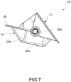
figure 7 is a side elevational view of the flap offigures 5 and 6 . -
Figures 1 to 4 represent a part of the casing of an air conditioning unit for a motor vehicle, indicated collectively at 10. -
Such casing 10 is made of plastic material and is conventionally configured in such a way as to have therein a set of passages for an air flow to be treated and introduced into the passenger compartment of a motor vehicle. - In particular, in
figure 4 , ahot air passage 11 and acold air passage 12 may be identified. Conventionally, thehot air passage 11 comes from an area (not shown) of the air conditioning unit wherein a heating device is located, while thecold air passage 12 comes from an area (not shown) of the air conditioning unit without a heater device. - The
hot air passage 11 and thecold air passage 12 converge into oneair inlet chamber 13, inside of which hot air and cold air may be mixed. - The
air inlet chamber 13 communicates with the outside of the air conditioning unit through a plurality of apertures, comprising a lowercentral outlet 14 and an uppercentral outlet 15, arranged at a higher level with respect thereto, as well as two side outlets 16 (only one of which is visible in the figures) arranged on opposite sides of thecentral outlets central outlets - In one embodiment, the lower
central outlet 14 is adapted to feed a front air vent (not shown) provided centrally on the vehicle's dashboard, the uppercentral outlet 15 is adapted to feed a front air vent (not shown) provided centrally on the vehicle's dashboard at a higher level than the first air vent, and thelower side outlets 16 are adapted to feed respective foot air vents (not shown) arranged in the lower part of the vehicle's interior. - In the figures, a central
air distribution passage 17 is also visible, also communicating with theair inlet chamber 13 and adapted to be connected to a further central air distribution outlet (not shown). - The figures also show a further
central outlet 19 communicating with theair inlet chamber 13 and typically provided for the defogging and defrosting of the windscreen, the presence of which is however irrelevant for the purposes of the present invention. - The device further comprises a
flap 20 made of plastic material for controlling the distribution of the air flow to thecentral outlets side outlets 16, as well as to thecentral passage 17. - With reference in particular to the
figures 5 to 7 , theflap 20 comprises two flat and coplanarside flap portions 21, and acentral flap portion 23, which interconnects the twoside flap portions 21, forming a single, continuous surface. - The
flap 20 is hinged to thecasing 10 of the air conditioning unit about a rotation axis x defined bypins 20a formed integrally with the body of theflap 20. Such rotation axis x is parallel to a plane defined by theside flap portions 21 and staggered with respect thereto. - The
central flap portion 23 comprises arostrum portion 24 having a V-shaped cross section defining on opposite faces of theflap 20 respectively arecess 24a and arelief 24b. Therecess 24a of therostrum part 24 has anedge 24c at least partly extending on a plane that is inclined in the direction of rotation of theflap 20, with respect to the plane defined by theside flap portions 21. Therecess 24a of therostrum part 24 is closed at the opposite ends bywall portions 24d. Therelief 24b of therostrum part 24 has aridge 24e extending on a plane that is inclined in the direction of rotation of the flap with respect to the plane defined by theside flap portions 21. - The
central flap portion 23 further comprises a flat and coplanar connectingpart 25 with theside flap portions 21. Therostrum part 24 is laterally connected to theside flap portions 21 and is at one end connected to the connectingpart 25. - The
central flap portion 23 comprises aflange part 26, which surrounds at least part of theedge 24c of therecess 24a of therostrum portion 24.Such flange part 26 extends on a plane that is inclined in the direction of rotation of the flap, with respect to the plane defined by theside flap portions 21. - As can be seen in
figures 1 to 4 , theflap 20 can be moved between a first terminal position in which thecentral openings figures 1 ,2a and2b ), and a second terminal position in which thecentral apertures figures 3 and4 ). In the first terminal position, the edges of the flap (i.e. the edges of the side flapportions 21, the connectingpart 25 and theflange part 26 of thecentral flap portion 23, as well as the edges of the walls connecting therostrum portion 24 and theflange part 26 to the side flap portions) fit together with the three-dimensional margin (represented collectively by the double dashed line infigure 2b ) of a passage section between theair inlet chamber 13 and thecentral apertures 14 and 15 (represented by the gray areas infigure 2b ). In this position (figure 2a ), therostrum part 24 of theflap 20 deflects the flow of air coming from thehot air passage 11 and/or thecold air passage 12 towards the side apertures 16 (as indicated by the arrows F1 infigure 2a ). In the second terminal position (figures 3 and4 ) the air flow is instead mainly directed towards thecentral apertures 14 and 15 (as indicated by the arrows F2 infigure 4 ). - It is understood that the invention is not limited to the embodiments described and illustrated here, but rather may undergo modifications relating to the shape and arrangement of parts, construction and operating details, according to the numerous possible variants which will appear suitable to persons skilled in the art and which are to be understood as included in the scope of the invention, as defined by the following claims.
Claims (4)
- An air distribution device for an air conditioning unit of a motor vehicle, comprising an air inlet chamber (13) to be supplied with an air flow and provided with a lower central outlet (14) and an upper central outlet (15) arranged at a level higher than the lower central outlet, as well as two side outlets (16) arranged on opposite sides of the central outlets (14, 15) and oriented substantially orthogonally to the central outlets (14, 15), and obstructing and deflecting means for distributing the air flow to said outlets;
characterized in that said obstructing and deflecting means comprise a flap (20) for controlling the distribution of the air flow to the central outlets (14, 15) and to the side outlets (16), said flap comprising two flat, coplanar side flap portions (21), and a central flap portion (23) that interconnects the two side flap portions (21) forming a single, continuous surface,
wherein the flap (20) is hinged about a rotation axis (x) parallel to a plane defined by the side flap portions (21), and staggered with respect thereto,
wherein the central flap portion (23) comprises a rostrum part (24) with a V-shaped cross section, defining on opposite faces of the flap (20) a recess (24a) and a relief (24b), respectively, wherein the recess (24a) of the rostrum part (24) has an edge (24c) at least partially extending in a plane that is inclined in the direction of rotation of the flap (20) with respect to the plane defined by the side flap portions (21), and wherein the relief (24b) of the rostrum part (24) has a ridge (24e) extending in a plane that is inclined in the direction of rotation of the flap (20) with respect to the plane defined by the side flap portions (21);
wherein the flap (20) is movable between a first terminal position, in which both central apertures (14, 15) are closed by the flap (20) and the rostrum part (24) of the flap (20) is capable of deflecting the air flow towards the side apertures (16), and a second terminal position, in which the central apertures (14, 15) are open. - A device according to claim 1, wherein the central flap portion (23) comprises a connection part (25), flat and coplanar with the side flap portions (21), the rostrum part (24) being laterally joined to the side flap portions (21) and being joined at an end to the connection part (25).
- A device according to claim 1 or 2, wherein the recess (24b) of the rostrum part (24) is on opposite ends closed by wall portions (24d).
- A device according to claim 3, wherein the central flap portion (23) comprises a flange part (26) that surrounds at least part of the edge (24c) of the recess (24a) of the rostrum part (24), said flange part (26) extending in a plane that is inclined in the direction of rotation of the flap (20) with respect to the plane defined by the side flap portions (21).
Applications Claiming Priority (1)
| Application Number | Priority Date | Filing Date | Title |
|---|---|---|---|
| IT102017000047479A IT201700047479A1 (en) | 2017-05-03 | 2017-05-03 | Air distribution device for an air conditioning unit of a motor vehicle. |
Publications (2)
| Publication Number | Publication Date |
|---|---|
| EP3401135A1 EP3401135A1 (en) | 2018-11-14 |
| EP3401135B1 true EP3401135B1 (en) | 2020-04-08 |
Family
ID=59811923
Family Applications (1)
| Application Number | Title | Priority Date | Filing Date |
|---|---|---|---|
| EP18169858.0A Active EP3401135B1 (en) | 2017-05-03 | 2018-04-27 | Air distribution device for an air conditioning unit of a motor vehicle |
Country Status (2)
| Country | Link |
|---|---|
| EP (1) | EP3401135B1 (en) |
| IT (1) | IT201700047479A1 (en) |
Family Cites Families (5)
| Publication number | Priority date | Publication date | Assignee | Title |
|---|---|---|---|---|
| JPS5741048Y2 (en) * | 1978-12-14 | 1982-09-09 | ||
| DE10352533A1 (en) * | 2003-11-07 | 2005-06-02 | Behr Gmbh & Co. Kg | drum flap |
| JP4525614B2 (en) * | 2006-03-01 | 2010-08-18 | 株式会社デンソー | Air conditioner for vehicles |
| EP1905622A1 (en) * | 2006-09-26 | 2008-04-02 | DENSO THERMAL SYSTEMS S.p.A. | Air distribution assembly for vehicles |
| BRPI0800275B1 (en) * | 2008-01-18 | 2019-09-24 | Valeo Sistemas Automotivos Ltda | SINGLE GATE FOR CLOSING CENTRAL AND SIDE AIR OUTLETS IN AN AUTOMOTIVE VEHICLE CLIMATE HABIT |
-
2017
- 2017-05-03 IT IT102017000047479A patent/IT201700047479A1/en unknown
-
2018
- 2018-04-27 EP EP18169858.0A patent/EP3401135B1/en active Active
Non-Patent Citations (1)
| Title |
|---|
| None * |
Also Published As
| Publication number | Publication date |
|---|---|
| EP3401135A1 (en) | 2018-11-14 |
| IT201700047479A1 (en) | 2018-11-03 |
Similar Documents
| Publication | Publication Date | Title |
|---|---|---|
| DE102016118973A1 (en) | Air conditioning system for vehicle | |
| KR20080026056A (en) | Method for adjusting the distribution flap and the corresponding distribution flap, in particular in the air duct housing for the automotive air conditioning system | |
| US20090318070A1 (en) | Louvre for an air-conduction housing of a vehicle air-conditioning system | |
| US10787154B2 (en) | Windshield defroster with secondary ducted outlet | |
| CN101563248A (en) | Air conditioning device for a vehicle comprising a defrost channel network | |
| CN107009849A (en) | Vehicular air conditioner | |
| JP2007510571A (en) | Drum flap | |
| CN101687458B (en) | Motor vehicle having an A-pillar | |
| JP3990276B2 (en) | Air guide box | |
| JP2003520731A (en) | Automotive air conditioner with separate treatment for the rear of the occupant compartment | |
| EP3401135A1 (en) | Air distribution device for an air conditioning unit of a motor vehicle | |
| KR102326366B1 (en) | Air conditioner for vehicle | |
| JP2005178759A (en) | An air distribution device based on the Coanda effect, having means for imparting a circulatory motion to an air flow that is not oriented in the proper direction | |
| KR102752358B1 (en) | Air conditioner for vehicle | |
| JP7785914B2 (en) | Housings for heating, ventilation, and/or air conditioning systems in motor vehicles | |
| KR101403436B1 (en) | Air conditioner for vehicle | |
| KR101492151B1 (en) | Air-conditioner in the vehicle | |
| KR102470404B1 (en) | Air conditioner for vehicle | |
| EP4470808B1 (en) | Heating and/or air conditioning device for a motor vehicle | |
| KR102379897B1 (en) | Modular vehicle air conditioning system | |
| JP7603089B2 (en) | Vehicle air conditioning system | |
| KR101320531B1 (en) | Air conditioner for vehicle | |
| KR20100016742A (en) | Air-conditioner in the vehicle | |
| KR101199683B1 (en) | Roof Duct for Rear Seat Air-conditioning of Vehicles | |
| KR20150129161A (en) | Air conditioner for vehicle |
Legal Events
| Date | Code | Title | Description |
|---|---|---|---|
| PUAI | Public reference made under article 153(3) epc to a published international application that has entered the european phase |
Free format text: ORIGINAL CODE: 0009012 |
|
| STAA | Information on the status of an ep patent application or granted ep patent |
Free format text: STATUS: THE APPLICATION HAS BEEN PUBLISHED |
|
| AK | Designated contracting states |
Kind code of ref document: A1 Designated state(s): AL AT BE BG CH CY CZ DE DK EE ES FI FR GB GR HR HU IE IS IT LI LT LU LV MC MK MT NL NO PL PT RO RS SE SI SK SM TR |
|
| AX | Request for extension of the european patent |
Extension state: BA ME |
|
| STAA | Information on the status of an ep patent application or granted ep patent |
Free format text: STATUS: REQUEST FOR EXAMINATION WAS MADE |
|
| 17P | Request for examination filed |
Effective date: 20190509 |
|
| RBV | Designated contracting states (corrected) |
Designated state(s): AL AT BE BG CH CY CZ DE DK EE ES FI FR GB GR HR HU IE IS IT LI LT LU LV MC MK MT NL NO PL PT RO RS SE SI SK SM TR |
|
| GRAP | Despatch of communication of intention to grant a patent |
Free format text: ORIGINAL CODE: EPIDOSNIGR1 |
|
| STAA | Information on the status of an ep patent application or granted ep patent |
Free format text: STATUS: GRANT OF PATENT IS INTENDED |
|
| INTG | Intention to grant announced |
Effective date: 20191029 |
|
| GRAS | Grant fee paid |
Free format text: ORIGINAL CODE: EPIDOSNIGR3 |
|
| GRAA | (expected) grant |
Free format text: ORIGINAL CODE: 0009210 |
|
| STAA | Information on the status of an ep patent application or granted ep patent |
Free format text: STATUS: THE PATENT HAS BEEN GRANTED |
|
| AK | Designated contracting states |
Kind code of ref document: B1 Designated state(s): AL AT BE BG CH CY CZ DE DK EE ES FI FR GB GR HR HU IE IS IT LI LT LU LV MC MK MT NL NO PL PT RO RS SE SI SK SM TR |
|
| REG | Reference to a national code |
Ref country code: CH Ref legal event code: EP Ref country code: AT Ref legal event code: REF Ref document number: 1253893 Country of ref document: AT Kind code of ref document: T Effective date: 20200415 |
|
| REG | Reference to a national code |
Ref country code: DE Ref legal event code: R096 Ref document number: 602018003528 Country of ref document: DE |
|
| REG | Reference to a national code |
Ref country code: IE Ref legal event code: FG4D |
|
| REG | Reference to a national code |
Ref country code: NL Ref legal event code: MP Effective date: 20200408 |
|
| REG | Reference to a national code |
Ref country code: LT Ref legal event code: MG4D |
|
| PG25 | Lapsed in a contracting state [announced via postgrant information from national office to epo] |
Ref country code: SE Free format text: LAPSE BECAUSE OF FAILURE TO SUBMIT A TRANSLATION OF THE DESCRIPTION OR TO PAY THE FEE WITHIN THE PRESCRIBED TIME-LIMIT Effective date: 20200408 Ref country code: NL Free format text: LAPSE BECAUSE OF FAILURE TO SUBMIT A TRANSLATION OF THE DESCRIPTION OR TO PAY THE FEE WITHIN THE PRESCRIBED TIME-LIMIT Effective date: 20200408 Ref country code: PT Free format text: LAPSE BECAUSE OF FAILURE TO SUBMIT A TRANSLATION OF THE DESCRIPTION OR TO PAY THE FEE WITHIN THE PRESCRIBED TIME-LIMIT Effective date: 20200817 Ref country code: NO Free format text: LAPSE BECAUSE OF FAILURE TO SUBMIT A TRANSLATION OF THE DESCRIPTION OR TO PAY THE FEE WITHIN THE PRESCRIBED TIME-LIMIT Effective date: 20200708 Ref country code: IS Free format text: LAPSE BECAUSE OF FAILURE TO SUBMIT A TRANSLATION OF THE DESCRIPTION OR TO PAY THE FEE WITHIN THE PRESCRIBED TIME-LIMIT Effective date: 20200808 Ref country code: FI Free format text: LAPSE BECAUSE OF FAILURE TO SUBMIT A TRANSLATION OF THE DESCRIPTION OR TO PAY THE FEE WITHIN THE PRESCRIBED TIME-LIMIT Effective date: 20200408 Ref country code: LT Free format text: LAPSE BECAUSE OF FAILURE TO SUBMIT A TRANSLATION OF THE DESCRIPTION OR TO PAY THE FEE WITHIN THE PRESCRIBED TIME-LIMIT Effective date: 20200408 Ref country code: GR Free format text: LAPSE BECAUSE OF FAILURE TO SUBMIT A TRANSLATION OF THE DESCRIPTION OR TO PAY THE FEE WITHIN THE PRESCRIBED TIME-LIMIT Effective date: 20200709 |
|
| REG | Reference to a national code |
Ref country code: AT Ref legal event code: MK05 Ref document number: 1253893 Country of ref document: AT Kind code of ref document: T Effective date: 20200408 |
|
| PG25 | Lapsed in a contracting state [announced via postgrant information from national office to epo] |
Ref country code: RS Free format text: LAPSE BECAUSE OF FAILURE TO SUBMIT A TRANSLATION OF THE DESCRIPTION OR TO PAY THE FEE WITHIN THE PRESCRIBED TIME-LIMIT Effective date: 20200408 Ref country code: BG Free format text: LAPSE BECAUSE OF FAILURE TO SUBMIT A TRANSLATION OF THE DESCRIPTION OR TO PAY THE FEE WITHIN THE PRESCRIBED TIME-LIMIT Effective date: 20200708 Ref country code: LV Free format text: LAPSE BECAUSE OF FAILURE TO SUBMIT A TRANSLATION OF THE DESCRIPTION OR TO PAY THE FEE WITHIN THE PRESCRIBED TIME-LIMIT Effective date: 20200408 Ref country code: HR Free format text: LAPSE BECAUSE OF FAILURE TO SUBMIT A TRANSLATION OF THE DESCRIPTION OR TO PAY THE FEE WITHIN THE PRESCRIBED TIME-LIMIT Effective date: 20200408 |
|
| PG25 | Lapsed in a contracting state [announced via postgrant information from national office to epo] |
Ref country code: AL Free format text: LAPSE BECAUSE OF FAILURE TO SUBMIT A TRANSLATION OF THE DESCRIPTION OR TO PAY THE FEE WITHIN THE PRESCRIBED TIME-LIMIT Effective date: 20200408 |
|
| REG | Reference to a national code |
Ref country code: DE Ref legal event code: R097 Ref document number: 602018003528 Country of ref document: DE |
|
| PG25 | Lapsed in a contracting state [announced via postgrant information from national office to epo] |
Ref country code: RO Free format text: LAPSE BECAUSE OF FAILURE TO SUBMIT A TRANSLATION OF THE DESCRIPTION OR TO PAY THE FEE WITHIN THE PRESCRIBED TIME-LIMIT Effective date: 20200408 Ref country code: IT Free format text: LAPSE BECAUSE OF FAILURE TO SUBMIT A TRANSLATION OF THE DESCRIPTION OR TO PAY THE FEE WITHIN THE PRESCRIBED TIME-LIMIT Effective date: 20200408 Ref country code: EE Free format text: LAPSE BECAUSE OF FAILURE TO SUBMIT A TRANSLATION OF THE DESCRIPTION OR TO PAY THE FEE WITHIN THE PRESCRIBED TIME-LIMIT Effective date: 20200408 Ref country code: SM Free format text: LAPSE BECAUSE OF FAILURE TO SUBMIT A TRANSLATION OF THE DESCRIPTION OR TO PAY THE FEE WITHIN THE PRESCRIBED TIME-LIMIT Effective date: 20200408 Ref country code: CZ Free format text: LAPSE BECAUSE OF FAILURE TO SUBMIT A TRANSLATION OF THE DESCRIPTION OR TO PAY THE FEE WITHIN THE PRESCRIBED TIME-LIMIT Effective date: 20200408 Ref country code: AT Free format text: LAPSE BECAUSE OF FAILURE TO SUBMIT A TRANSLATION OF THE DESCRIPTION OR TO PAY THE FEE WITHIN THE PRESCRIBED TIME-LIMIT Effective date: 20200408 Ref country code: LU Free format text: LAPSE BECAUSE OF NON-PAYMENT OF DUE FEES Effective date: 20200427 Ref country code: DK Free format text: LAPSE BECAUSE OF FAILURE TO SUBMIT A TRANSLATION OF THE DESCRIPTION OR TO PAY THE FEE WITHIN THE PRESCRIBED TIME-LIMIT Effective date: 20200408 Ref country code: ES Free format text: LAPSE BECAUSE OF FAILURE TO SUBMIT A TRANSLATION OF THE DESCRIPTION OR TO PAY THE FEE WITHIN THE PRESCRIBED TIME-LIMIT Effective date: 20200408 Ref country code: MC Free format text: LAPSE BECAUSE OF FAILURE TO SUBMIT A TRANSLATION OF THE DESCRIPTION OR TO PAY THE FEE WITHIN THE PRESCRIBED TIME-LIMIT Effective date: 20200408 |
|
| REG | Reference to a national code |
Ref country code: BE Ref legal event code: MM Effective date: 20200430 |
|
| PLBE | No opposition filed within time limit |
Free format text: ORIGINAL CODE: 0009261 |
|
| STAA | Information on the status of an ep patent application or granted ep patent |
Free format text: STATUS: NO OPPOSITION FILED WITHIN TIME LIMIT |
|
| PG25 | Lapsed in a contracting state [announced via postgrant information from national office to epo] |
Ref country code: PL Free format text: LAPSE BECAUSE OF FAILURE TO SUBMIT A TRANSLATION OF THE DESCRIPTION OR TO PAY THE FEE WITHIN THE PRESCRIBED TIME-LIMIT Effective date: 20200408 Ref country code: SK Free format text: LAPSE BECAUSE OF FAILURE TO SUBMIT A TRANSLATION OF THE DESCRIPTION OR TO PAY THE FEE WITHIN THE PRESCRIBED TIME-LIMIT Effective date: 20200408 Ref country code: BE Free format text: LAPSE BECAUSE OF NON-PAYMENT OF DUE FEES Effective date: 20200430 |
|
| 26N | No opposition filed |
Effective date: 20210112 |
|
| PG25 | Lapsed in a contracting state [announced via postgrant information from national office to epo] |
Ref country code: IE Free format text: LAPSE BECAUSE OF NON-PAYMENT OF DUE FEES Effective date: 20200427 |
|
| PG25 | Lapsed in a contracting state [announced via postgrant information from national office to epo] |
Ref country code: SI Free format text: LAPSE BECAUSE OF FAILURE TO SUBMIT A TRANSLATION OF THE DESCRIPTION OR TO PAY THE FEE WITHIN THE PRESCRIBED TIME-LIMIT Effective date: 20200408 |
|
| PG25 | Lapsed in a contracting state [announced via postgrant information from national office to epo] |
Ref country code: CH Free format text: LAPSE BECAUSE OF NON-PAYMENT OF DUE FEES Effective date: 20210430 Ref country code: LI Free format text: LAPSE BECAUSE OF NON-PAYMENT OF DUE FEES Effective date: 20210430 |
|
| PG25 | Lapsed in a contracting state [announced via postgrant information from national office to epo] |
Ref country code: TR Free format text: LAPSE BECAUSE OF FAILURE TO SUBMIT A TRANSLATION OF THE DESCRIPTION OR TO PAY THE FEE WITHIN THE PRESCRIBED TIME-LIMIT Effective date: 20200408 Ref country code: MT Free format text: LAPSE BECAUSE OF FAILURE TO SUBMIT A TRANSLATION OF THE DESCRIPTION OR TO PAY THE FEE WITHIN THE PRESCRIBED TIME-LIMIT Effective date: 20200408 Ref country code: CY Free format text: LAPSE BECAUSE OF FAILURE TO SUBMIT A TRANSLATION OF THE DESCRIPTION OR TO PAY THE FEE WITHIN THE PRESCRIBED TIME-LIMIT Effective date: 20200408 |
|
| PG25 | Lapsed in a contracting state [announced via postgrant information from national office to epo] |
Ref country code: MK Free format text: LAPSE BECAUSE OF FAILURE TO SUBMIT A TRANSLATION OF THE DESCRIPTION OR TO PAY THE FEE WITHIN THE PRESCRIBED TIME-LIMIT Effective date: 20200408 |
|
| GBPC | Gb: european patent ceased through non-payment of renewal fee |
Effective date: 20220427 |
|
| PG25 | Lapsed in a contracting state [announced via postgrant information from national office to epo] |
Ref country code: GB Free format text: LAPSE BECAUSE OF NON-PAYMENT OF DUE FEES Effective date: 20220427 |
|
| PGFP | Annual fee paid to national office [announced via postgrant information from national office to epo] |
Ref country code: DE Payment date: 20250424 Year of fee payment: 8 |
|
| PGFP | Annual fee paid to national office [announced via postgrant information from national office to epo] |
Ref country code: FR Payment date: 20260331 Year of fee payment: 9 |