EP3401062B1 - Handwerkzeug und verfahren zur herstellung eines handwerkzeugs - Google Patents
Handwerkzeug und verfahren zur herstellung eines handwerkzeugs Download PDFInfo
- Publication number
- EP3401062B1 EP3401062B1 EP18157521.8A EP18157521A EP3401062B1 EP 3401062 B1 EP3401062 B1 EP 3401062B1 EP 18157521 A EP18157521 A EP 18157521A EP 3401062 B1 EP3401062 B1 EP 3401062B1
- Authority
- EP
- European Patent Office
- Prior art keywords
- motor
- receptacle
- tool
- hand tool
- drive device
- Prior art date
- Legal status (The legal status is an assumption and is not a legal conclusion. Google has not performed a legal analysis and makes no representation as to the accuracy of the status listed.)
- Active
Links
Images

Classifications
-
- B—PERFORMING OPERATIONS; TRANSPORTING
- B25—HAND TOOLS; PORTABLE POWER-DRIVEN TOOLS; MANIPULATORS
- B25B—TOOLS OR BENCH DEVICES NOT OTHERWISE PROVIDED FOR, FOR FASTENING, CONNECTING, DISENGAGING, OR HOLDING
- B25B21/00—Portable power-driven screw or nut setting or loosening tools; Attachments for drilling apparatus serving the same purpose
Definitions
- the invention relates to a hand tool with a handle and a tool part, the handle having a receptacle for receiving a motor and the tool part being rotatable about a longitudinal axis of the hand tool by means of a drive device having the motor.
- the invention also relates to a method for producing a hand tool which has at least the features of the hand tool described above.
- a hand tool of the type mentioned is from the DE 10 2015 205 122 A1 known. It is customary in the prior art to fit the motor in the receptacle in such a way that the motor is firmly seated in the receptacle in the handle.
- the pamphlet US 5017109 A discloses a pneumatic tool in which a molded-on motor cylinder is arranged in a cylindrical outer housing.
- the motor cylinder has threads for fixing.
- the invention is based on the object of a to create alternative mounting options for the motor.
- the features of claim 1 are provided according to the invention.
- the invention proposes in a hand tool of the type mentioned that the motor is arranged in the receptacle with play, a free space defined by the play between the motor and the receptacle being filled with a casting compound.
- the invention can achieve shock absorption of the motor against mechanical loads and / or sealing of the motor.
- a weak point can be formed for actuating the motor through which moisture can penetrate. This can be prevented by the invention.
- the hand tool can be designed as a screwdriver, for example. However, the hand tool can also be any other manually operable tool in which a tool part is intended to execute a rotary movement for machining.
- the tool part can be a machining element such as a tool blade. This can be inserted or inserted directly into the handle. However, it can also be inserted or inserted into a blade holder, which in turn can be brought into engagement with the handle.
- the tool part can thus also be provided by the blade holder or also by the blade holder mechanically connected to a blade.
- the tool part can therefore also be an adapter piece such as a blade holder, a Act bit holder or a bit holder or another tool element such as a torque limiter.
- the tool part can consist of a single part or also be composed of several individual parts.
- the tool part can be mechanically connected to the handle in such a way that it is not exchangeable. In other configurations, the tool part can also be exchangeable. In particular, it can be removable from and / or removable from the handle.
- the tool part is arranged on a tool-side end of the handle.
- the tool part can be arranged directly on the handle or at a distance therefrom, with a further element being arranged between the tool part and the handle, which element is in operative connection with both the handle and the tool part.
- the tool part can be inserted or inserted into the handle, for example.
- the tool part can be rotatable relative to the handle.
- the receptacle forms a cavity within which the entire motor is arranged. This can be advantageous, since in this way the motor can be better protected against mechanical impairments and / or impairments that affect the hand tool from the environment.
- control electronics of the drive device are encapsulated with the casting compound. It can also be provided that the entire drive device is filled with the casting compound. As a result, in addition to the motor, another important element of the drive device or even the entire drive device can be better protected.
- the poured casting compound precisely forms a spatial association.
- This can have the advantage, for example, that it can facilitate the manufacture of the hand tool.
- Such a spatial association can be produced in a single casting process.
- a spatial association can also improve the shock absorption and / or the sealing, since several separate cast areas can lead to areas of the partially encapsulated parts being particularly exposed to mechanical stress and / or accessibility of a fluid.
- the casting compound completely encases the motor and / or the control electronics and / or the entire drive device.
- the motor is not round.
- the receptacle is not round.
- the motor and / or the receptacle is preferably not round in a plane oriented perpendicular to the longitudinal axis. This can be particularly advantageous because in this plane there is a particular risk of the motor rotating in the receptacle. It can be particularly advantageous if the non-round configuration of the Motor is such that it fits into the clearance recess of the non-circular configuration of the mount. For this purpose, the non-circular design of the motor can in particular correspond to the non-circular design of the receptacle.
- the features of the independent claim directed to a method are also provided according to the invention.
- the motor be arranged in the receptacle of the handle with a play and that a free space defined by the play between the motor and the receptacle is then filled with a casting compound becomes.
- control electronics of the drive device are filled with the casting compound.
- the entire drive device is filled with the casting compound.
- the free space and / or the drive device and / or the motor and / or the control electronics are preferably poured out in a common pouring process.
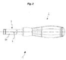
- Fig. 1 and Fig. 2 show an exemplary embodiment of a hand tool 1 according to the invention designed as a screwdriver with a handle 2 and a tool part 4 that is rotatable with respect to the handle 2 and designed as a bit holder 22.
- the tool part 4 is arranged directly on a tool-side end of the handle 2.
- the tool part 4 is not exchangeable. In an alternative exemplary embodiment, however, the tool part 4 is exchangeable and can thus be removed from the handle 2 or removed therefrom.
- a torque attachment 24 is inserted into the bit holder 22.
- a tool bit (not shown), an adapter piece or a tool blade can then be inserted into the bit holder 22 or into the torque attachment 24, for example.
- the tool blade can then also be rotated with respect to the handle 2.
- FIG. 1 As can be seen, the area of the motor 8 and the control electronics 20, which each form a part of the drive device 10, is shown in an open sectional view.
- a longitudinal axis 6 is formed in the hand tool 1. This longitudinal axis 6 forms a central axis of the hand tool 1 and at the same time an axis of rotation about which the tool part 4 can be rotated.
- the hand tool 1 has the motor 8, which is let into the receptacle 12 of the handle 2.
- the receptacle 12 forms a cavity 18 in which the motor 8 is completely contained.
- the motor 8 is controlled by the control electronics 20.
- the motor 8 and the control electronics 20 form part of the drive device 10.
- the motor 8 is an in Fig. 1 and Fig. 2 Shaft not shown can be driven, which is operatively connected to the tool part 4 in such a way that a rotation of the shaft causes a corresponding rotation of the tool part 4. If, for example, a screw blade is inserted into the tool part 4, the screwing process can be carried out by the rotation that is effected.
- the motor 8 is fed by a battery which is arranged on a handle section on the user side within the handle 2.
- a battery which is arranged on a handle section on the user side within the handle 2.
- the battery is shown covered by the grip surface and is therefore not visible.
- a free space 14 which is filled with a casting compound 16, is formed between the receptacle 12 and the outer housing of the motor 8.
- the motor 8 thus has an outside diameter transversely to the axis of rotation which is somewhat smaller than the inside diameter of the receptacle 12, so that there remains a play between the motor 8 and the receptacle 12.
- the motor 8 and the receptacle 12 are not round.
- the motor 8 and the receptacle 12 are elliptical in a plane perpendicular to the longitudinal axis 6 educated.
- the motor 8 is completely encased by the casting compound 16.
- the control electronics 20 are also filled with the casting compound 16. This took place in a common casting process, so that the casting compound 16 forms a common association.
- the casting compound 16 therefore does not break down into several areas, but instead each casting area is cast-connected to a different casting area of the casting compound 16.
- a motor-operated hand tool 1 it is proposed to arrange the motor 8 in a receptacle 12 of the handle 2 of the hand tool 1 with play, a free space 14 defined by the play between the motor 8 and the receptacle 12 being filled with a casting compound 16.
Landscapes
- Engineering & Computer Science (AREA)
- Mechanical Engineering (AREA)
- Portable Power Tools In General (AREA)
- Pinball Game Machines (AREA)
Description
- Die Erfindung betrifft ein Handwerkzeug mit einem Griff und einem Werkzeugteil, wobei der Griff eine Aufnahme zur Aufnahme eines Motors aufweist und wobei das Werkzeugteil um eine Längsachse des Handwerkzeugs mittels einer den Motor aufweisenden Antriebseinrichtung rotierbar ist.
- Die Erfindung betrifft ferner ein Verfahren zur Herstellung eines Handwerkzeugs, welches zumindest die Merkmale des eingangs beschriebenen Handwerkzeugs aufweist.
- Ein Handwerkzeug der eingangs genannten Art ist aus der
DE 10 2015 205 122 A1 bekannt. Es ist nach dem Stand der Technik üblich, den Motor in der Weise in der Aufnahme einzupassen, dass ein fester Sitz des Motors in der Aufnahme im Griff erreicht ist. - Die Druckschrift
US 5017109 A offenbart ein pneumatisches Werkzeug, bei dem ein angespritzter Motorzylinder in einem zylinderförmigen Außengehäuse angeordnet wird. Der Motorzylinder weist zur Fixierung Gewinde auf. - Der Erfindung liegt die Aufgabe zugrunde, eine alternative Befestigungsmöglichkeit des Motors zu schaffen.
- Zur Lösung der Aufgabe sind erfindungsgemäß die Merkmale des Anspruchs 1 vorgesehen. Insbesondere wird somit zur Lösung der genannten Aufgabe erfindungsgemäß bei einem Handwerkzeug der eingangs genannten Art vorgeschlagen, dass der Motor in der Aufnahme mit einem Spiel angeordnet ist, wobei ein durch das Spiel definierter Freiraum zwischen dem Motor und der Aufnahme mit einer Gussmasse ausgegossen ist.
- Hierdurch kann die Erfindung eine Stoßdämpfung des Motors gegenüber mechanischen Belastungen und/oder eine Abdichtung des Motors erreichen.
- So kann beispielsweise nach dem Stand der Technik zur Betätigung des Motors eine Schwachstelle ausgebildet sein, durch die Feuchtigkeit eindringen kann. Dies kann durch die Erfindung verhindert werden.
- Das Handwerkzeug kann beispielsweise als Schraubendreher ausgebildet sein. Bei dem Handwerkzeug kann es sich aber auch um ein beliebiges anderes manuell bedienbares Werkzeug handeln, bei dem ein Werkzeugteil zur Bearbeitung eine Drehbewegung ausführen soll.
- Das Werkzeugteil kann ein Bearbeitungselement sein wie beispielsweise eine Werkzeugklinge. Diese kann unmittelbar in den Griff eingesetzt oder einsetzbar sein. Sie kann aber auch in einem Klingenhalter eingesetzt oder einsetzbar sein, welcher seinerseits in Eingriff mit dem Griff bringbar ist. Das Werkzeugteil kann somit auch durch den Klingenhalter gegeben sein oder auch durch den mit einer Klinge mechanisch verbundenen Klingenhalter. Bei dem Werkzeugteil kann es sich daher auch um ein Adapterstück wie einem Klingenhalter, einem Bithalter oder einer Bitaufnahme handeln oder auch um ein anderes Werkzeugelement wie beispielsweise ein Drehmomentbegrenzer. Das Werkzeugteil kann aus einem Einzelteil bestehen oder auch aus mehreren Einzelteilen zusammengesetzt sein.
- Das Werkzeugteil kann derart mit dem Griff mechanisch verbunden sein, dass es nicht austauschbar ist. In anderen Ausgestaltungen kann das Werkzeugteil auch austauschbar sein. Insbesondere kann es von dem Griff entfernbar und/oder aus diesem herausnehmbar sein.
- Es kann vorgesehen sein, dass das Werkzeugteil an einem werkzeugseitigen Ende des Griffs angeordnet ist. Dabei kann das Werkzeugteil unmittelbar am Griff angeordnet sein oder auch beabstandet von diesem, wobei zwischen dem Werkzeugteil und dem Griff ein weiteres Element angeordnet ist, welches sowohl mit dem Griff als auch mit dem Werkzeugteil in Wirkverbindung steht.
- Das Werkzeugteil kann beispielsweise in den Griff einsetzbar oder eingesetzt sein. Das Werkzeugteil kann gegenüber dem Griff rotierbar sein.
- Bei einer Ausgestaltung des erfindungsgemäßen Handwerkzeugs kann vorgesehen sein, dass die Aufnahme einen Hohlraum bildet, innerhalb dessen der gesamte Motor angeordnet ist. Dies kann vorteilhaft sein, da so der Motor besser vor mechanischen und/oder aus der Umgebung an das Handwerkzeug gelangenden Beeinträchtigungen geschützt werden kann.
- Erfindungsgemäß ist bei dem Handwerkzeug vorgesehen,, dass eine Ansteuerungselektronik der Antriebseinrichtung mit der Gussmasse ausgegossen ist. Es kann auch vorgesehen sein, dass die gesamte Antriebseinrichtung mit der Gussmasse ausgegossen ist. Hierdurch kann neben dem Motor auch ein weiteres wichtiges Element der Antriebseinrichtung oder sogar die gesamte Antriebseinrichtung besser geschützt werden.
- Bei einer weiteren Ausgestaltung des erfindungsgemäßen Handwerkzeugs kann vorgesehen sein, dass die ausgegossene Gussmasse genau einen räumlichen Verband bildet. Dies kann beispielsweise den Vorteil haben, dass hierdurch die Herstellung des Handwerkzeugs erleichtert werden kann. So kann ein solcher räumlicher Verband durch einen einzigen Gießvorgang hergestellt werden. Ein räumlicher Verband kann auch die Stoßdämpfung und/oder die Abdichtung verbessern, da mehrere voneinander getrennte Gussbereiche dazu führen können, dass Bereiche der teilweise umgossenen Teile einer mechanischen Belastung und/oder einer Zugänglichkeit eines Fluids besonders ausgesetzt sind.
- Um die Stoßdämpfung und/oder die Abdichtung weiter zu verbessern, kann bei einer weiteren Ausgestaltung des erfindungsgemäßen Handwerkzeugs vorgesehen sein, dass die Gussmasse den Motor und/oder die Ansteuerungselektronik und/oder die gesamte Antriebseinrichtung lückenlos ummantelt.
- Um ein Durchdrehen des Motors zu verhindern, kann bei einer weiteren Ausgestaltung des erfindungsgemäßen Handwerkzeugs vorgesehen sein, dass der Motor unrund ausgebildet ist. Alternativ oder zusätzlich kann vorgesehen sein, dass die Aufnahme unrund ausgebildet ist. Bevorzugt ist der Motor und/oder die Aufnahme in einer zur Längsachse senkrecht orientierten Ebene unrund ausgebildet. Dies kann besonders vorteilhaft sein, da in dieser Ebene eine Verdrehung des Motors in der Aufnahme in besonderen Maß droht. Besonders vorteilhaft kann es sein, wenn die unrunde Ausgestaltung des Motors derart ist, dass er in die Spielaufnehmung der unrunden Ausgestaltung der Aufnahme eingepasst ist. Hierzu kann die unrunde Ausgestaltung des Motors insbesondere der unrunden Ausgestaltung der Aufnahme entsprechen.
- Zur Lösung der genannten Aufgabe sind außerdem erfindungsgemäß die Merkmale des nebengeordneten, auf ein Verfahren gerichteten Anspruchs vorgesehenen. Insbesondere wird somit zur Lösung der genannten Aufgabe erfindungsgemäß bei einem Verfahren der eingangs beschriebenen Art vorgeschlagen, dass der Motor in der Aufnahme des Griffes mit einem Spiel angeordnet wird und dass sodann ein durch das Spiel definierter Freiraum zwischen dem Motor und der Aufnahme mit einer Gussmasse ausgegossen wird. Durch dieses Verfahren ist somit auf einfache Weise ein Handwerkzeug herstellbar, welches robuster ist gegen mechanische Belastungen und/oder besser abgedichtet ist als herkömmliche Handwerkzeuge der eingangs beschriebenen Art. So kann mittels des genannten Verfahrens insbesondere ein Handwerkzeug hergestellt werden, welches erfindungsgemäß, insbesondere wie zuvor beschrieben und/oder nach einem der auf ein Handwerkzeug gerichteten Schutzansprüche, ausgebildet ist.
- Zur Vereinfachung der Werkzeugherstellung und/oder zur Verbesserung der Werkzeugeigenschaften ist bei dem Verfahren erfindungsgemäß vorgesehen, dass eine Ansteuerungselektronik der Antriebseinrichtung mit der Gussmasse ausgegossen wird. Alternativ oder zusätzlich kann vorgesehen sein, dass die gesamte Antriebseinrichtung mit der Gussmasse ausgegossen wird. Bevorzugt erfolgt das Ausgießen des Freiraums und/oder der Antriebseinrichtung und/oder des Motors und/oder der Ansteuerungselektronik in einem gemeinsamen Gießvorgang.
- Die Erfindung wird nun anhand eines oder einiger weniger Ausführungsbeispiele näher beschrieben, ist jedoch nicht auf diese wenigen Ausführungsbeispiele beschränkt. Weitere Ausführungsbeispiele ergeben sich durch Kombination der Merkmale einzelner oder mehrerer Schutzansprüche untereinander und/oder mit einzelnen oder mehreren Merkmalen der Ausführungsbeispiele.
- Es zeigt:
- Fig. 1
- ein Ausführungsbeispiel eines erfindungsgemäßen Handwerkzeugs 1;
- Fig. 2
- das Handwerkzeug 1 gemäß
Fig. 1 mit einem eingesetzten Drehmomentaufsatz 24. -
Fig. 1 undFig. 2 zeigen ein Ausführungsbeispiel eines erfindungsgemäßen als Schraubendreher ausgebildeten Handwerkzeugs 1 mit einem Griff 2 und einem gegenüber dem Griff 2 rotierbaren und als Bitaufnahme 22 ausgebildeten Werkzeugteil 4. Das Werkzeugteil 4 ist unmittelbar an einem werkzeugseitigen Ende des Griffs 2 angeordnet. Das Werkzeugteil 4 ist nicht austauschbar. In einem alternativen Ausführungsbeispiel ist das Werkzeugteil 4 allerdings austauschbar und somit von dem Griff 2 entfernbar oder aus diesem herausnehmbar. InFig. 2 ist in die Bitaufnahme 22 ein Drehmomentaufsatz 24 eingesetzt. Zum eigentlichen Gebrauch kann sodann beispielsweise ein nicht abgebildetes Werkzeugbit, ein Adapterstück oder eine Werkzeugklinge in die Bitaufnahme 22 oder in den Drehmomentaufsatz 24 eingesetzt sein. So ist dann auch die Werkzeugklinge gegenüber dem Griff 2 rotierbar. - Wie aus
Fig. 1 ersichtlich, ist der Bereich des Motors 8 und der Ansteuerungselektronik 20, welche jeweils einen Teil der Antriebseinrichtung 10 bilden, in offener Schnittdarstellung dargestellt. - Bei dem Handwerkzeug 1 ist eine Längsachse 6 ausgebildet. Diese Längsachse 6 bildet eine Mittelachse des Handwerkzeugs 1 und zugleich eine Rotationsachse, um welche das Werkzeugteil 4 rotierbar ist.
- Hierzu weist das Handwerkzeug 1 den Motor 8 auf, welcher in die Aufnahme 12 des Griffes 2 eingelassen ist. Die Aufnahme 12 bildet dabei einen Hohlraum 18, in dem der Motor 8 vollständig enthalten ist. Der Motor 8 wird von der Ansteuerungselektronik 20 angesteuert. Dabei bilden der Motor 8 und die Ansteuerungselektronik 20 einen Teil der Antriebseinrichtung 10. Mit dem Motor 8 ist eine in
Fig. 1 undFig. 2 nicht dargestellte Welle antreibbar, welche mit dem Werkzeugteil 4 in der Weise wirkverbunden ist, dass eine Rotation der Welle eine entsprechende Rotation des Werkzeugteils 4 bewirkt. Wird beispielsweise eine Schraubklinge in das Werkzeugteil 4 eingesetzt, so kann durch die bewirkte Rotation der Schraubvorgang ausgeführt werden. - Der Motor 8 wird von einer Batterie gespeist, welche an einem nutzerseitigen Griffabschnitt innerhalb des Griffes 2 angeordnet ist. In
Fig. 1 undFig. 2 ist die Batterie von der Griffoberfläche bedeckt dargestellt und daher nicht sichtbar. - Bei dem Handwerkzeug 1 ist zwischen der Aufnahme 12 und dem Außengehäuse des Motors 8 ein Freiraum 14 ausgebildet, welcher mit einer Gussmasse 16 ausgegossen ist. Der Motor 8 weist somit quer zur Rotationsachse einen Außendurchmesser auf, welche etwas geringer ist als der Innendurchmesser der Aufnahme 12, so dass ein Spiel zwischen dem Motor 8 und der Aufnahme 12 verbleibt. Dabei sind der Motor 8 und die Aufnahme 12 unrund ausgebildet. In dem Ausführungsbeispiel gemäß
Fig. 1 undFig. 2 sind der Motor 8 und die Aufnahme 12 in einer Ebene senkrecht zur Längsachse 6 elliptisch ausgebildet. - In dem in
Fig. 1 undFig. 2 gezeigten Ausführungsbeispiel ist der Motor 8 lückenlos von der Gussmasse 16 ummantelt. Ferner ist neben dem Motor 8 auch die Ansteuerungselektronik 20 mit der Gussmasse 16 ausgegossen. Dies erfolgte in einem gemeinsamen Gussvorgang, so dass die Gussmasse 16 einen gemeinsamen Verband bildet. Die Gussmasse 16 zerfällt somit nicht in mehrere Bereiche, sondern jeder Gussbereich ist mit einem anderen Gussbereich der Gussmasse 16 gussverbunden. - Es wird vorgeschlagen, bei einem motorbetriebenen Handwerkzeug 1 den Motor 8 in einer Aufnahme 12 des Griffes 2 des Handwerkzeugs 1 mit einem Spiel anzuordnen, wobei ein durch das Spiel definierter Freiraum 14 zwischen dem Motor 8 und der Aufnahme 12 mit einer Gussmasse 16 ausgegossen ist.
-
- 1
- Handwerkzeug
- 2
- Griff
- 4
- Werkzeugteil
- 6
- Längsachse
- 8
- Motor
- 10
- Antriebseinrichtung
- 12
- Aufnahme
- 14
- Freiraum
- 16
- Gussmasse
- 18
- Hohlraum
- 20
- Ansteuerungselektronik
- 22
- Bitaufnahme
- 24
- Drehmomentaufsatz
Claims (7)
- Handwerkzeug (1) mit einem Griff (2) und einem Werkzeugteil (4), wobei der Griff (2) eine Aufnahme (12) zur Aufnahme eines Motors (8) aufweist und wobei das Werkzeugteil (4) um eine Längsachse (6) des Handwerkzeugs (1) mittels einer den Motor (8) aufweisenden Antriebseinrichtung (10) rotierbar ist, dadurch gekennzeichnet, dass der Motor (8) in der Aufnahme (12) mit einem Spiel angeordnet ist, wobei ein durch das Spiel definierter Freiraum (14) zwischen dem Motor (8) und der Aufnahme (12) und eine Ansteuerungselektronik (20) der Antriebseinrichtung (10) mit einer Gussmasse (16) ausgegossen sind.
- Handwerkzeug (1) nach dem vorangehenden Anspruch, dadurch gekennzeichnet, dass die Aufnahme (12) einen Hohlraum (18) bildet, innerhalb dessen der gesamte Motor (8) angeordnet ist.
- Handwerkzeug (1) nach einem der vorangehenden Ansprüche, dadurch gekennzeichnet, dass die Antriebseinrichtung (10) mit der Gussmasse (16) ausgegossen ist.
- Handwerkzeug (1) nach einem der vorangehenden Ansprüche, dadurch gekennzeichnet, dass die ausgegossene Gussmasse (16) genau einen räumlichen Verband bildet und/oder dass die Gussmasse (16) den Motor (8) und/oder die Ansteuerungselektronik (20) und/oder die Antriebseinrichtung (10) lückenlos ummantelt.
- Handwerkzeug (1) nach einem der vorangehenden Ansprüche, dadurch gekennzeichnet, dass der Motor (8) und/oder die Aufnahme (12) unrund ausgebildet ist, insbesondere wobei der Motor (8) und/oder die Aufnahme (12) in einer zur Längsachse (6) senkrecht orientierten Ebene unrund ausgebildet ist.
- Verfahren zur Herstellung eines Handwerkzeugs (1) nach dem Oberbegriff von Anspruch 1, insbesondere nach einem der vorangehenden Ansprüche, dadurch gekennzeichnet, dass der Motor (8) in der Aufnahme (12) des Griffes (2) mit einem Spiel angeordnet wird und dass sodann ein durch das Spiel definierter Freiraum (14) zwischen dem Motor (8) und der Aufnahme (12) und eine Ansteuerungselektronik (20) der Antriebseinrichtung (10) mit einer Gussmasse (16) ausgegossen werden.
- Verfahren nach dem vorangehenden Anspruch, dadurch gekennzeichnet, dass die Antriebseinrichtung (10) mit der Gussmasse (16) ausgegossen wird, insbesondere wobei das Ausgießen des Freiraums (14) und/oder der Antriebseinrichtung (10) und/oder des Motors (8) und/oder der Ansteuerungselektronik (16) in einem gemeinsamen Gießvorgang erfolgt.
Applications Claiming Priority (1)
| Application Number | Priority Date | Filing Date | Title |
|---|---|---|---|
| DE102017109123.8A DE102017109123A1 (de) | 2017-04-27 | 2017-04-27 | Handwerkzeug und Verfahren zur Herstellung eines Handwerkzeugs |
Publications (2)
| Publication Number | Publication Date |
|---|---|
| EP3401062A1 EP3401062A1 (de) | 2018-11-14 |
| EP3401062B1 true EP3401062B1 (de) | 2020-12-23 |
Family
ID=61249534
Family Applications (1)
| Application Number | Title | Priority Date | Filing Date |
|---|---|---|---|
| EP18157521.8A Active EP3401062B1 (de) | 2017-04-27 | 2018-02-20 | Handwerkzeug und verfahren zur herstellung eines handwerkzeugs |
Country Status (4)
| Country | Link |
|---|---|
| EP (1) | EP3401062B1 (de) |
| CN (1) | CN208100287U (de) |
| DE (1) | DE102017109123A1 (de) |
| ES (1) | ES2848731T3 (de) |
Family Cites Families (4)
| Publication number | Priority date | Publication date | Assignee | Title |
|---|---|---|---|---|
| US5017109A (en) * | 1990-01-26 | 1991-05-21 | Ingersoll-Rand Company | Cylinder and housing assembly for pneumatic tool |
| DE102010018581A1 (de) * | 2010-04-27 | 2011-10-27 | Wiha Werkzeuge Gmbh | Schraubendreher |
| WO2013037325A1 (zh) * | 2011-09-16 | 2013-03-21 | 苏州宝时得电动工具有限公司 | 电工螺丝批和便携式手持工具 |
| DE102015205122B4 (de) | 2015-03-20 | 2020-02-20 | Wiha Werkzeuge Gmbh | Schraubendreher |
-
2017
- 2017-04-27 DE DE102017109123.8A patent/DE102017109123A1/de not_active Withdrawn
-
2018
- 2018-02-20 ES ES18157521T patent/ES2848731T3/es active Active
- 2018-02-20 EP EP18157521.8A patent/EP3401062B1/de active Active
- 2018-03-28 CN CN201820426374.3U patent/CN208100287U/zh active Active
Non-Patent Citations (1)
| Title |
|---|
| None * |
Also Published As
| Publication number | Publication date |
|---|---|
| ES2848731T3 (es) | 2021-08-11 |
| DE102017109123A1 (de) | 2018-10-31 |
| CN208100287U (zh) | 2018-11-16 |
| EP3401062A1 (de) | 2018-11-14 |
Similar Documents
| Publication | Publication Date | Title |
|---|---|---|
| EP3261805B1 (de) | Handwerkzeugmaschine | |
| EP2262601B1 (de) | Handwerkzeugmaschine | |
| DE69501485T2 (de) | Angetriebener Schrauber mit abgewinkeltem Kopf | |
| EP2689071B2 (de) | Grundankersystem | |
| DE3242862C2 (de) | ||
| CH643130A5 (de) | Handgeraet von langgestreckter form, insbesondere fuer chirurgische eingriffe, und verfahren zu dessen herstellung. | |
| EP2428297B1 (de) | Spannfutter | |
| EP3038780B1 (de) | Gegengewichtsvorrichtung | |
| EP2266732B1 (de) | Spannsystem | |
| DE4239559C2 (de) | Handwerkzeugmaschine mit einer Blockiereinrichtung zum Blockieren der Werkzeugspindel beim Werkzeugwechsel | |
| DE202017102523U1 (de) | Abzieher | |
| EP0240917A2 (de) | Bohrvorrichtung zur Herstellung von Bohrlöchern mit Hinterschneidung | |
| DE19507391C2 (de) | Schraubvorrichtung zum ultraschallgesteuerten Anziehen von Schraubverbindungen | |
| EP1929973A1 (de) | Instrumentenschaft für ein rotierendes Instrument | |
| EP3401062A1 (de) | Handwerkzeug und verfahren zur herstellung eines handwerkzeugs | |
| DE102008001252A1 (de) | Werkzeugmaschine, insbesondere Handwerkzeugmaschine | |
| DE102014209398A1 (de) | Schlagkörper für ein mechanisches Drehschlagwerk | |
| DE19605068C2 (de) | Schraubverbindung | |
| EP0054721A1 (de) | Bohrer, insbesondere Gesteinsbohrer | |
| DE10124443B4 (de) | Werkzeugmaschine zur Demontage festsitzender Muttern | |
| DE3616731C2 (de) | ||
| DE102024120220B4 (de) | Vorrichtung zur Begrenzung einer Bohrtiefe für eine Bohrmaschine | |
| DE102014224556B3 (de) | Spannfutter | |
| DE102013005288B4 (de) | Motorischer Antrieb | |
| DE3241698A1 (de) | Winkelschleifmaschine |
Legal Events
| Date | Code | Title | Description |
|---|---|---|---|
| PUAI | Public reference made under article 153(3) epc to a published international application that has entered the european phase |
Free format text: ORIGINAL CODE: 0009012 |
|
| STAA | Information on the status of an ep patent application or granted ep patent |
Free format text: STATUS: THE APPLICATION HAS BEEN PUBLISHED |
|
| AK | Designated contracting states |
Kind code of ref document: A1 Designated state(s): AL AT BE BG CH CY CZ DE DK EE ES FI FR GB GR HR HU IE IS IT LI LT LU LV MC MK MT NL NO PL PT RO RS SE SI SK SM TR |
|
| AX | Request for extension of the european patent |
Extension state: BA ME |
|
| STAA | Information on the status of an ep patent application or granted ep patent |
Free format text: STATUS: REQUEST FOR EXAMINATION WAS MADE |
|
| 17P | Request for examination filed |
Effective date: 20190327 |
|
| RBV | Designated contracting states (corrected) |
Designated state(s): AL AT BE BG CH CY CZ DE DK EE ES FI FR GB GR HR HU IE IS IT LI LT LU LV MC MK MT NL NO PL PT RO RS SE SI SK SM TR |
|
| GRAP | Despatch of communication of intention to grant a patent |
Free format text: ORIGINAL CODE: EPIDOSNIGR1 |
|
| STAA | Information on the status of an ep patent application or granted ep patent |
Free format text: STATUS: GRANT OF PATENT IS INTENDED |
|
| INTG | Intention to grant announced |
Effective date: 20200729 |
|
| GRAS | Grant fee paid |
Free format text: ORIGINAL CODE: EPIDOSNIGR3 |
|
| GRAA | (expected) grant |
Free format text: ORIGINAL CODE: 0009210 |
|
| STAA | Information on the status of an ep patent application or granted ep patent |
Free format text: STATUS: THE PATENT HAS BEEN GRANTED |
|
| AK | Designated contracting states |
Kind code of ref document: B1 Designated state(s): AL AT BE BG CH CY CZ DE DK EE ES FI FR GB GR HR HU IE IS IT LI LT LU LV MC MK MT NL NO PL PT RO RS SE SI SK SM TR |
|
| REG | Reference to a national code |
Ref country code: GB Ref legal event code: FG4D Free format text: NOT ENGLISH |
|
| REG | Reference to a national code |
Ref country code: DE Ref legal event code: R096 Ref document number: 502018003369 Country of ref document: DE |
|
| REG | Reference to a national code |
Ref country code: AT Ref legal event code: REF Ref document number: 1347281 Country of ref document: AT Kind code of ref document: T Effective date: 20210115 |
|
| REG | Reference to a national code |
Ref country code: IE Ref legal event code: FG4D Free format text: LANGUAGE OF EP DOCUMENT: GERMAN |
|
| PG25 | Lapsed in a contracting state [announced via postgrant information from national office to epo] |
Ref country code: RS Free format text: LAPSE BECAUSE OF FAILURE TO SUBMIT A TRANSLATION OF THE DESCRIPTION OR TO PAY THE FEE WITHIN THE PRESCRIBED TIME-LIMIT Effective date: 20201223 Ref country code: FI Free format text: LAPSE BECAUSE OF FAILURE TO SUBMIT A TRANSLATION OF THE DESCRIPTION OR TO PAY THE FEE WITHIN THE PRESCRIBED TIME-LIMIT Effective date: 20201223 Ref country code: NO Free format text: LAPSE BECAUSE OF FAILURE TO SUBMIT A TRANSLATION OF THE DESCRIPTION OR TO PAY THE FEE WITHIN THE PRESCRIBED TIME-LIMIT Effective date: 20210323 Ref country code: GR Free format text: LAPSE BECAUSE OF FAILURE TO SUBMIT A TRANSLATION OF THE DESCRIPTION OR TO PAY THE FEE WITHIN THE PRESCRIBED TIME-LIMIT Effective date: 20210324 |
|
| REG | Reference to a national code |
Ref country code: NL Ref legal event code: MP Effective date: 20201223 |
|
| PG25 | Lapsed in a contracting state [announced via postgrant information from national office to epo] |
Ref country code: BG Free format text: LAPSE BECAUSE OF FAILURE TO SUBMIT A TRANSLATION OF THE DESCRIPTION OR TO PAY THE FEE WITHIN THE PRESCRIBED TIME-LIMIT Effective date: 20210323 Ref country code: LV Free format text: LAPSE BECAUSE OF FAILURE TO SUBMIT A TRANSLATION OF THE DESCRIPTION OR TO PAY THE FEE WITHIN THE PRESCRIBED TIME-LIMIT Effective date: 20201223 Ref country code: SE Free format text: LAPSE BECAUSE OF FAILURE TO SUBMIT A TRANSLATION OF THE DESCRIPTION OR TO PAY THE FEE WITHIN THE PRESCRIBED TIME-LIMIT Effective date: 20201223 |
|
| PG25 | Lapsed in a contracting state [announced via postgrant information from national office to epo] |
Ref country code: NL Free format text: LAPSE BECAUSE OF FAILURE TO SUBMIT A TRANSLATION OF THE DESCRIPTION OR TO PAY THE FEE WITHIN THE PRESCRIBED TIME-LIMIT Effective date: 20201223 Ref country code: HR Free format text: LAPSE BECAUSE OF FAILURE TO SUBMIT A TRANSLATION OF THE DESCRIPTION OR TO PAY THE FEE WITHIN THE PRESCRIBED TIME-LIMIT Effective date: 20201223 |
|
| REG | Reference to a national code |
Ref country code: LT Ref legal event code: MG9D |
|
| PG25 | Lapsed in a contracting state [announced via postgrant information from national office to epo] |
Ref country code: RO Free format text: LAPSE BECAUSE OF FAILURE TO SUBMIT A TRANSLATION OF THE DESCRIPTION OR TO PAY THE FEE WITHIN THE PRESCRIBED TIME-LIMIT Effective date: 20201223 Ref country code: SK Free format text: LAPSE BECAUSE OF FAILURE TO SUBMIT A TRANSLATION OF THE DESCRIPTION OR TO PAY THE FEE WITHIN THE PRESCRIBED TIME-LIMIT Effective date: 20201223 Ref country code: PT Free format text: LAPSE BECAUSE OF FAILURE TO SUBMIT A TRANSLATION OF THE DESCRIPTION OR TO PAY THE FEE WITHIN THE PRESCRIBED TIME-LIMIT Effective date: 20210423 Ref country code: SM Free format text: LAPSE BECAUSE OF FAILURE TO SUBMIT A TRANSLATION OF THE DESCRIPTION OR TO PAY THE FEE WITHIN THE PRESCRIBED TIME-LIMIT Effective date: 20201223 Ref country code: LT Free format text: LAPSE BECAUSE OF FAILURE TO SUBMIT A TRANSLATION OF THE DESCRIPTION OR TO PAY THE FEE WITHIN THE PRESCRIBED TIME-LIMIT Effective date: 20201223 Ref country code: CZ Free format text: LAPSE BECAUSE OF FAILURE TO SUBMIT A TRANSLATION OF THE DESCRIPTION OR TO PAY THE FEE WITHIN THE PRESCRIBED TIME-LIMIT Effective date: 20201223 Ref country code: EE Free format text: LAPSE BECAUSE OF FAILURE TO SUBMIT A TRANSLATION OF THE DESCRIPTION OR TO PAY THE FEE WITHIN THE PRESCRIBED TIME-LIMIT Effective date: 20201223 |
|
| REG | Reference to a national code |
Ref country code: ES Ref legal event code: FG2A Ref document number: 2848731 Country of ref document: ES Kind code of ref document: T3 Effective date: 20210811 |
|
| PG25 | Lapsed in a contracting state [announced via postgrant information from national office to epo] |
Ref country code: PL Free format text: LAPSE BECAUSE OF FAILURE TO SUBMIT A TRANSLATION OF THE DESCRIPTION OR TO PAY THE FEE WITHIN THE PRESCRIBED TIME-LIMIT Effective date: 20201223 |
|
| REG | Reference to a national code |
Ref country code: DE Ref legal event code: R097 Ref document number: 502018003369 Country of ref document: DE |
|
| PG25 | Lapsed in a contracting state [announced via postgrant information from national office to epo] |
Ref country code: IS Free format text: LAPSE BECAUSE OF FAILURE TO SUBMIT A TRANSLATION OF THE DESCRIPTION OR TO PAY THE FEE WITHIN THE PRESCRIBED TIME-LIMIT Effective date: 20210423 Ref country code: MC Free format text: LAPSE BECAUSE OF FAILURE TO SUBMIT A TRANSLATION OF THE DESCRIPTION OR TO PAY THE FEE WITHIN THE PRESCRIBED TIME-LIMIT Effective date: 20201223 |
|
| REG | Reference to a national code |
Ref country code: BE Ref legal event code: MM Effective date: 20210228 |
|
| PG25 | Lapsed in a contracting state [announced via postgrant information from national office to epo] |
Ref country code: AL Free format text: LAPSE BECAUSE OF FAILURE TO SUBMIT A TRANSLATION OF THE DESCRIPTION OR TO PAY THE FEE WITHIN THE PRESCRIBED TIME-LIMIT Effective date: 20201223 Ref country code: CH Free format text: LAPSE BECAUSE OF NON-PAYMENT OF DUE FEES Effective date: 20210228 Ref country code: IT Free format text: LAPSE BECAUSE OF FAILURE TO SUBMIT A TRANSLATION OF THE DESCRIPTION OR TO PAY THE FEE WITHIN THE PRESCRIBED TIME-LIMIT Effective date: 20201223 Ref country code: LU Free format text: LAPSE BECAUSE OF NON-PAYMENT OF DUE FEES Effective date: 20210220 Ref country code: LI Free format text: LAPSE BECAUSE OF NON-PAYMENT OF DUE FEES Effective date: 20210228 |
|
| PLBE | No opposition filed within time limit |
Free format text: ORIGINAL CODE: 0009261 |
|
| STAA | Information on the status of an ep patent application or granted ep patent |
Free format text: STATUS: NO OPPOSITION FILED WITHIN TIME LIMIT |
|
| PG25 | Lapsed in a contracting state [announced via postgrant information from national office to epo] |
Ref country code: DK Free format text: LAPSE BECAUSE OF FAILURE TO SUBMIT A TRANSLATION OF THE DESCRIPTION OR TO PAY THE FEE WITHIN THE PRESCRIBED TIME-LIMIT Effective date: 20201223 |
|
| 26N | No opposition filed |
Effective date: 20210924 |
|
| PG25 | Lapsed in a contracting state [announced via postgrant information from national office to epo] |
Ref country code: IE Free format text: LAPSE BECAUSE OF NON-PAYMENT OF DUE FEES Effective date: 20210220 |
|
| PG25 | Lapsed in a contracting state [announced via postgrant information from national office to epo] |
Ref country code: SI Free format text: LAPSE BECAUSE OF FAILURE TO SUBMIT A TRANSLATION OF THE DESCRIPTION OR TO PAY THE FEE WITHIN THE PRESCRIBED TIME-LIMIT Effective date: 20201223 |
|
| PGFP | Annual fee paid to national office [announced via postgrant information from national office to epo] |
Ref country code: GB Payment date: 20220221 Year of fee payment: 5 |
|
| PG25 | Lapsed in a contracting state [announced via postgrant information from national office to epo] |
Ref country code: IS Free format text: LAPSE BECAUSE OF FAILURE TO SUBMIT A TRANSLATION OF THE DESCRIPTION OR TO PAY THE FEE WITHIN THE PRESCRIBED TIME-LIMIT Effective date: 20210423 |
|
| PGFP | Annual fee paid to national office [announced via postgrant information from national office to epo] |
Ref country code: FR Payment date: 20220221 Year of fee payment: 5 Ref country code: ES Payment date: 20220318 Year of fee payment: 5 |
|
| PG25 | Lapsed in a contracting state [announced via postgrant information from national office to epo] |
Ref country code: BE Free format text: LAPSE BECAUSE OF NON-PAYMENT OF DUE FEES Effective date: 20210228 |
|
| PG25 | Lapsed in a contracting state [announced via postgrant information from national office to epo] |
Ref country code: CY Free format text: LAPSE BECAUSE OF FAILURE TO SUBMIT A TRANSLATION OF THE DESCRIPTION OR TO PAY THE FEE WITHIN THE PRESCRIBED TIME-LIMIT Effective date: 20201223 |
|
| PG25 | Lapsed in a contracting state [announced via postgrant information from national office to epo] |
Ref country code: HU Free format text: LAPSE BECAUSE OF FAILURE TO SUBMIT A TRANSLATION OF THE DESCRIPTION OR TO PAY THE FEE WITHIN THE PRESCRIBED TIME-LIMIT; INVALID AB INITIO Effective date: 20180220 |
|
| GBPC | Gb: european patent ceased through non-payment of renewal fee |
Effective date: 20230220 |
|
| PG25 | Lapsed in a contracting state [announced via postgrant information from national office to epo] |
Ref country code: GB Free format text: LAPSE BECAUSE OF NON-PAYMENT OF DUE FEES Effective date: 20230220 |
|
| PG25 | Lapsed in a contracting state [announced via postgrant information from national office to epo] |
Ref country code: GB Free format text: LAPSE BECAUSE OF NON-PAYMENT OF DUE FEES Effective date: 20230220 Ref country code: FR Free format text: LAPSE BECAUSE OF NON-PAYMENT OF DUE FEES Effective date: 20230228 |
|
| REG | Reference to a national code |
Ref country code: ES Ref legal event code: FD2A Effective date: 20240402 |
|
| REG | Reference to a national code |
Ref country code: AT Ref legal event code: MM01 Ref document number: 1347281 Country of ref document: AT Kind code of ref document: T Effective date: 20230220 |
|
| PG25 | Lapsed in a contracting state [announced via postgrant information from national office to epo] |
Ref country code: ES Free format text: LAPSE BECAUSE OF NON-PAYMENT OF DUE FEES Effective date: 20230221 |
|
| PG25 | Lapsed in a contracting state [announced via postgrant information from national office to epo] |
Ref country code: AT Free format text: LAPSE BECAUSE OF NON-PAYMENT OF DUE FEES Effective date: 20230220 |
|
| PG25 | Lapsed in a contracting state [announced via postgrant information from national office to epo] |
Ref country code: MK Free format text: LAPSE BECAUSE OF FAILURE TO SUBMIT A TRANSLATION OF THE DESCRIPTION OR TO PAY THE FEE WITHIN THE PRESCRIBED TIME-LIMIT Effective date: 20201223 Ref country code: ES Free format text: LAPSE BECAUSE OF NON-PAYMENT OF DUE FEES Effective date: 20230221 Ref country code: AT Free format text: LAPSE BECAUSE OF NON-PAYMENT OF DUE FEES Effective date: 20230220 |
|
| PG25 | Lapsed in a contracting state [announced via postgrant information from national office to epo] |
Ref country code: MT Free format text: LAPSE BECAUSE OF FAILURE TO SUBMIT A TRANSLATION OF THE DESCRIPTION OR TO PAY THE FEE WITHIN THE PRESCRIBED TIME-LIMIT Effective date: 20201223 |
|
| PG25 | Lapsed in a contracting state [announced via postgrant information from national office to epo] |
Ref country code: TR Free format text: LAPSE BECAUSE OF FAILURE TO SUBMIT A TRANSLATION OF THE DESCRIPTION OR TO PAY THE FEE WITHIN THE PRESCRIBED TIME-LIMIT Effective date: 20201223 |
|
| PGFP | Annual fee paid to national office [announced via postgrant information from national office to epo] |
Ref country code: DE Payment date: 20260330 Year of fee payment: 9 |
|
| PGFP | Annual fee paid to national office [announced via postgrant information from national office to epo] |
Ref country code: AT Payment date: 20260410 Year of fee payment: 5 |