EP3401003B1 - Wet scrubber tower with plates between nozzles for wet flue gas desulphurisation and particulate matter removal - Google Patents
Wet scrubber tower with plates between nozzles for wet flue gas desulphurisation and particulate matter removal Download PDFInfo
- Publication number
- EP3401003B1 EP3401003B1 EP17170576.7A EP17170576A EP3401003B1 EP 3401003 B1 EP3401003 B1 EP 3401003B1 EP 17170576 A EP17170576 A EP 17170576A EP 3401003 B1 EP3401003 B1 EP 3401003B1
- Authority
- EP
- European Patent Office
- Prior art keywords
- flue gas
- degrees
- plates
- wet scrubber
- nozzles
- Prior art date
- Legal status (The legal status is an assumption and is not a legal conclusion. Google has not performed a legal analysis and makes no representation as to the accuracy of the status listed.)
- Active
Links
Images


Classifications
-
- B—PERFORMING OPERATIONS; TRANSPORTING
- B01—PHYSICAL OR CHEMICAL PROCESSES OR APPARATUS IN GENERAL
- B01D—SEPARATION
- B01D53/00—Separation of gases or vapours; Recovering vapours of volatile solvents from gases; Chemical or biological purification of waste gases, e.g. engine exhaust gases, smoke, fumes, flue gases, aerosols
- B01D53/34—Chemical or biological purification of waste gases
- B01D53/46—Removing components of defined structure
- B01D53/48—Sulfur compounds
- B01D53/50—Sulfur oxides
- B01D53/501—Sulfur oxides by treating the gases with a solution or a suspension of an alkali or earth-alkali or ammonium compound
- B01D53/504—Sulfur oxides by treating the gases with a solution or a suspension of an alkali or earth-alkali or ammonium compound characterised by a specific device
-
- B—PERFORMING OPERATIONS; TRANSPORTING
- B01—PHYSICAL OR CHEMICAL PROCESSES OR APPARATUS IN GENERAL
- B01D—SEPARATION
- B01D47/00—Separating dispersed particles from gases, air or vapours by liquid as separating agent
- B01D47/06—Spray cleaning
-
- B—PERFORMING OPERATIONS; TRANSPORTING
- B01—PHYSICAL OR CHEMICAL PROCESSES OR APPARATUS IN GENERAL
- B01D—SEPARATION
- B01D47/00—Separating dispersed particles from gases, air or vapours by liquid as separating agent
- B01D47/06—Spray cleaning
- B01D47/063—Spray cleaning with two or more jets impinging against each other
-
- B—PERFORMING OPERATIONS; TRANSPORTING
- B01—PHYSICAL OR CHEMICAL PROCESSES OR APPARATUS IN GENERAL
- B01D—SEPARATION
- B01D53/00—Separation of gases or vapours; Recovering vapours of volatile solvents from gases; Chemical or biological purification of waste gases, e.g. engine exhaust gases, smoke, fumes, flue gases, aerosols
- B01D53/14—Separation of gases or vapours; Recovering vapours of volatile solvents from gases; Chemical or biological purification of waste gases, e.g. engine exhaust gases, smoke, fumes, flue gases, aerosols by absorption
- B01D53/1456—Removing acid components
- B01D53/1481—Removing sulfur dioxide or sulfur trioxide
-
- B—PERFORMING OPERATIONS; TRANSPORTING
- B01—PHYSICAL OR CHEMICAL PROCESSES OR APPARATUS IN GENERAL
- B01D—SEPARATION
- B01D53/00—Separation of gases or vapours; Recovering vapours of volatile solvents from gases; Chemical or biological purification of waste gases, e.g. engine exhaust gases, smoke, fumes, flue gases, aerosols
- B01D53/14—Separation of gases or vapours; Recovering vapours of volatile solvents from gases; Chemical or biological purification of waste gases, e.g. engine exhaust gases, smoke, fumes, flue gases, aerosols by absorption
- B01D53/18—Absorbing units; Liquid distributors therefor
-
- B—PERFORMING OPERATIONS; TRANSPORTING
- B01—PHYSICAL OR CHEMICAL PROCESSES OR APPARATUS IN GENERAL
- B01D—SEPARATION
- B01D53/00—Separation of gases or vapours; Recovering vapours of volatile solvents from gases; Chemical or biological purification of waste gases, e.g. engine exhaust gases, smoke, fumes, flue gases, aerosols
- B01D53/34—Chemical or biological purification of waste gases
- B01D53/74—General processes for purification of waste gases; Apparatus or devices specially adapted therefor
- B01D53/77—Liquid phase processes
- B01D53/78—Liquid phase processes with gas-liquid contact
-
- F—MECHANICAL ENGINEERING; LIGHTING; HEATING; WEAPONS; BLASTING
- F23—COMBUSTION APPARATUS; COMBUSTION PROCESSES
- F23J—REMOVAL OR TREATMENT OF COMBUSTION PRODUCTS OR COMBUSTION RESIDUES; FLUES
- F23J15/00—Arrangements of devices for treating smoke or fumes
- F23J15/02—Arrangements of devices for treating smoke or fumes of purifiers, e.g. for removing noxious material
- F23J15/04—Arrangements of devices for treating smoke or fumes of purifiers, e.g. for removing noxious material using washing fluids
-
- B—PERFORMING OPERATIONS; TRANSPORTING
- B01—PHYSICAL OR CHEMICAL PROCESSES OR APPARATUS IN GENERAL
- B01D—SEPARATION
- B01D2247/00—Details relating to the separation of dispersed particles from gases, air or vapours by liquid as separating agent
- B01D2247/08—Means for controlling the separation process
-
- B—PERFORMING OPERATIONS; TRANSPORTING
- B01—PHYSICAL OR CHEMICAL PROCESSES OR APPARATUS IN GENERAL
- B01D—SEPARATION
- B01D2247/00—Details relating to the separation of dispersed particles from gases, air or vapours by liquid as separating agent
- B01D2247/10—Means for removing the washing fluid dispersed in the gas or vapours
- B01D2247/107—Means for removing the washing fluid dispersed in the gas or vapours using an unstructured demister, e.g. a wire mesh demister
-
- B—PERFORMING OPERATIONS; TRANSPORTING
- B01—PHYSICAL OR CHEMICAL PROCESSES OR APPARATUS IN GENERAL
- B01D—SEPARATION
- B01D2251/00—Reactants
- B01D2251/40—Alkaline earth metal or magnesium compounds
- B01D2251/404—Alkaline earth metal or magnesium compounds of calcium
-
- B—PERFORMING OPERATIONS; TRANSPORTING
- B01—PHYSICAL OR CHEMICAL PROCESSES OR APPARATUS IN GENERAL
- B01D—SEPARATION
- B01D2251/00—Reactants
- B01D2251/60—Inorganic bases or salts
- B01D2251/602—Oxides
-
- B—PERFORMING OPERATIONS; TRANSPORTING
- B01—PHYSICAL OR CHEMICAL PROCESSES OR APPARATUS IN GENERAL
- B01D—SEPARATION
- B01D2251/00—Reactants
- B01D2251/60—Inorganic bases or salts
- B01D2251/606—Carbonates
-
- B—PERFORMING OPERATIONS; TRANSPORTING
- B01—PHYSICAL OR CHEMICAL PROCESSES OR APPARATUS IN GENERAL
- B01D—SEPARATION
- B01D2257/00—Components to be removed
- B01D2257/30—Sulfur compounds
- B01D2257/302—Sulfur oxides
-
- B—PERFORMING OPERATIONS; TRANSPORTING
- B01—PHYSICAL OR CHEMICAL PROCESSES OR APPARATUS IN GENERAL
- B01D—SEPARATION
- B01D2258/00—Sources of waste gases
- B01D2258/02—Other waste gases
- B01D2258/0283—Flue gases
-
- B—PERFORMING OPERATIONS; TRANSPORTING
- B01—PHYSICAL OR CHEMICAL PROCESSES OR APPARATUS IN GENERAL
- B01D—SEPARATION
- B01D2259/00—Type of treatment
- B01D2259/12—Methods and means for introducing reactants
- B01D2259/124—Liquid reactants
-
- F—MECHANICAL ENGINEERING; LIGHTING; HEATING; WEAPONS; BLASTING
- F23—COMBUSTION APPARATUS; COMBUSTION PROCESSES
- F23J—REMOVAL OR TREATMENT OF COMBUSTION PRODUCTS OR COMBUSTION RESIDUES; FLUES
- F23J2215/00—Preventing emissions
- F23J2215/20—Sulfur; Compounds thereof
Definitions
- Another system embodiment according to the present disclosure comprises a wet scrubber tower with an at least first spray level arrangement equipped with a plurality of upwardly spraying nozzles, and a plurality of single and double plates arranged in a pattern with respect to the upwardly spraying nozzles to increase flue gas flow velocity and to increase flue gas contact with absorption liquid atomised within a wet scrubber tower.
- the pattern of the plurality of single and double plates increases the flue gas flow velocity and increases flue gas contact with absorption liquid atomised within the wet scrubber tower to generate an intermixed cloud of flue gas and absorption liquid. This intermixed cloud of flue gas and absorption liquid yields very efficient absorption of flue gas pollutants, such as sulphur dioxide, and efficient capture of particulate matter.
- Another system embodiment according to the present disclosure comprises a wet scrubber tower with an at least first spray level arrangement equipped with a plurality of individual and/or combination downwardly and upwardly spraying nozzles, and a plurality of single and double plates arranged in a pattern with respect to the downwardly and upwardly spraying nozzles to increase flue gas flow velocity and to increase flue gas contact with absorption liquid atomised within a wet scrubber tower.
- the pattern of the plurality of single and double plates increases the flue gas flow velocity and increases flue gas contact with absorption liquid atomised within the wet scrubber tower to generate an intermixed cloud of flue gas and absorption liquid. This intermixed cloud of flue gas and absorption liquid yields very efficient absorption of flue gas pollutants, such as sulphur dioxide, and efficient capture of particulate matter.
- open areas between adjacent single plates arranged at a common or varying angles within a common horizontal plane within the wet scrubber tower as that of the downwardly spraying nozzles, and open areas between adjacent double plates arranged at common or varying angles within a common horizontal plane within the wet scrubber tower above that of the downwardly spraying nozzles and staggered with respect to the single plates increases upward flow velocity of flue gas through the open areas to a velocity of about 5 m/s to about 15 m/s.
- Such arrangement of the single and double plates effectively reduces the cross-sectional area of the wet scrubber tower throughwhich the flue gas flows, thereby increasing flue gas flow velocity to about 5 m/s to about 15 m/s.
- open areas between adjacent double plates arranged at common or varying angles within a common horizontal plane within the wet scrubber tower below that of the upwardly spraying nozzles increases upward flow velocity of flue gas through the open areas to a velocity of about 5 m/s to about 15 m/s.
- Such arrangement of the double plates effectively reduces the cross-sectional area of the wet scrubber tower throughwhich the flue gas flows, thereby increasing flue gas flow velocity to about 5 m/s to about 15 m/s.
- such arrangement of the angled double plates affects flue gas flow for increased flue gas flow into direct contact with the absorption liquid spray for increased sulphur dioxide absorption efficiency and for increased particulate matter capture efficiency by the absorption liquid.
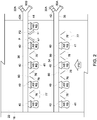
- the wet scrubber 14 of WFGD system 12 comprises a vertical open wet scrubber tower 16 with an interior area 22, and a flue gas inlet 24 fluidly connected to duct 18A for flue gas FG flow through interior area 22 and out of the wet scrubber tower 16 through flue gas outlet 26 as cleaned flue gas CG.
- Cleaned flue gas CG flowing out from flue gas outlet 26 is flue gas FG from which at least a portion of the sulphur oxide and/or particulate matter content has been removed.
- This adjustment in the supply rate and/or the supply ratio of alkaline absorbent liquid/slurry AS and/or the at least partially reacted slurry RS is based at least in part on the sulfite sensor 72 obtained sulfite concentration measurement of the sulfite concentration S 1 of the at least partially reacted slurry RS in tank 50.
- sulfite concentration S 1 /sulfite concentration measurement is less than the predetermined sulfite concentration
- software 74 executing on the controller 68 generates an electronic signal to affect adjustment of one or more of the valves 42, 42A to a more open position with respect to the supply of alkaline absorbent liquid/slurry AS, to affect adjustment of one or more of the pumps 66, 66A to increase the supply of at least partially reacted slurry RS, or both, thus supplying more alkaline absorbent liquid/slurry AS and/or at least partially reacted slurry RS to the at least first spray level arrangement 34 and/or second spray level arrangement 36, thereby increasing the sulfite concentration S 1 thereof.
- control of the pH of the at least partially reacted slurry RS is achieved by controlling the supply of fresh alkaline absorbent liquid/slurry AS through valves 42, 42A.
- software 74 executing on the controller 68 generates an electronic signal to affect adjustment of one or more of the valves 42, 42A to a more closed position with respect to the supply of alkaline absorbent liquid/slurry AS, thus supplying less alkaline absorbent liquid/slurry AS to the at least first spray level arrangement 34 and/or the second spray level arrangement 36, thereby decreasing the pH thereof.
- This adjustment in the supply rate and/or the supply ratio of absorbent liquid/slurry AS and/or the at least partially reacted slurry RS, and/or the number of spray level arrangements 34, 36 in operation, is based at least in part on the one or more sulphur oxide and/or particulate matter sensors 72B obtained sulphur oxide and/or particulate matter measurement(s) of the cleaned flue gas CG at flue gas outlet 26.
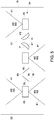
- a single plate 76A may be an open base 97 hollow interior 98 cone, triangular prism, pyramid, or other three-dimensional geometric or non-geometric form to achieve desired flue gas FG flow within wet scrubber tower 16.
- one or more single plates 76A, as well as single plates 76 and double plates 82, may include one or more perforations 99 extending therethrough, such as from exterior surface 96 to interior surface 96A. Arrangement of pairs of single plates 76 within wet scrubber tower 16 increases flue gas FG flow velocity and increases flue gas FG contact with alkaline absorbent liquid/slurry AS/at least partially reacted slurry RS atomised within wet scrubber tower 16.
- the plurality of single plates 76 increases the flue gas FG flow velocity and increases flue gas FG contact with alkaline absorbent liquid/slurry AS/at least partially reacted slurry RS atomised within the wet scrubber tower 16 to generate an increased shear force impact of flue gas FG with alkaline absorbent liquid/slurry AS/at least partially reacted slurry RS.
- This increased shear force impact of flue gas FG with alkaline absorbent liquid/slurry AS/at least partially reacted slurry RS yields very efficient absorption/capture of flue gas pollutants, such as sulphur oxides and/or particulate matter.
- first portions 88 and second portions 88A may be square, circular, triangular, oblong, or other two-dimensional geometric or non-geometric form to achieve desired flue gas FG flow within wet scrubber tower 16.
- one or more double plates 82 may include one or more perforations 99 therethrough, such as illustrated in Figure 15 with respect to single plate 76A. Arrangement of double plates 82 within wet scrubber tower 16 increases flue gas FG flow velocity and increases flue gas FG contact with alkaline absorbent liquid/slurry AS/at least partially reacted slurry RS atomised within wet scrubber tower 16.
- first portions 88 and second portions 88A may be square, circular, oblong, or other geometric or non-geometric two-dimensional form to achieve desired flue gas FG flow within wet scrubber tower 16.
- one or more double plates 82 may include one or more perforations 99 therethrough, such as illustrated in Figure 15 with respect to single plate 76A. Arrangement of double plates 82 within wet scrubber tower 16 increases flue gas FG flow velocity and increases flue gas FG contact with alkaline absorbent liquid/slurry AS/at least partially reacted slurry RS atomised within wet scrubber tower 16.
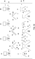
- Each of the double plates 82 is arranged with upstream edges 84 relatively distanced one from the other and a common downstream apex 86. Extending from upstream edge 84 to downstream apex 86 are planes P3, P4. Hence, first portion 88 of double plate 82 has a plane P3 with a positive angle ⁇ + of about 0 degrees to about 60 degrees with respect to horizontal, or about 15 degrees to about 40 degrees with respect to horizontal, and second portion 88A of double plate 82 has a plane P4 with a negative angle ⁇ - of about 0 degrees to about 60 degrees with respect to horizontal, or about 15 degrees to about 40 degrees with respect to horizontal with first portion 88 and second portion 88A joining at common downstream apex 86.
- First portions 88 and second portions 88A may be planar, curved, corrugated, or otherwise formed to achieve desired flue gas FG flow within wet scrubber tower 16. Likewise, first portions 88 and second portions 88A may be square, circular, oblong, or other two-dimensional geometric or non-geometric form to achieve desired flue gas FG flow within wet scrubber tower 16. Further, one or more double plates 82 may include one or more perforations 99 therethrough, such as illustrated in Figure 15 with respect to single plate 76A.
- first portion 88 of double plate 82 has a plane P3 with a positive angle ⁇ + of about 0 degrees to about 60 degrees with respect to horizontal, or about 15 degrees to about 40 degrees with respect to horizontal
- second portion 88A of double plate 82 has a plane P4 with a negative angle ⁇ - of about 0 degrees to about 60 degrees with respect to horizontal, or about 15 degrees to about 40 degrees with respect to horizontal with first portion 88 and second portion 88A joining at common upstream apex 90.
- First portions 88 and second portions 88A may be planar, curved, corrugated, or otherwise formed to achieve desired flue gas FG flow within wet scrubber tower 16.
- the plurality of single plates 76 and plurality of double plates 82 increase the flue gas FG flow velocity and increase flue gas FG contact with alkaline absorbent liquid/slurry AS/at least partially reacted slurry RS atomised within the wet scrubber tower 16 to generate an increased shear force impact of flue gas FG with alkaline absorbent liquid/slurry AS/at least partially reacted slurry RS.
- This increased shear force impact of flue gas FG with alkaline absorbent liquid/slurry AS/at least partially reacted slurry RS yields very efficient absorption/capture of flue gas pollutants, such as sulphur oxides and/or particulate matter.
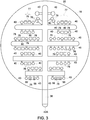
- the plurality of double plates 82 are each arranged with a common downstream apex 86 arranged just below each of the upwardly spraying nozzles 40. As such, each of the double plates 82 is arranged with upstream edges 84 relatively distanced one from the other and a common downstream apex 86. Extending from upstream edge 84 to downstream apex 86 are planes P3, P4.
- the plurality of single plates 76 and plurality of double plates 82 increase the flue gas FG flow velocity and increase flue gas FG contact with alkaline absorbent liquid/slurry AS/at least partially reacted slurry RS atomised within the wet scrubber tower 16 to generate an increased shear force impact of flue gas FG with alkaline absorbent liquid/slurry AS/at least partially reacted slurry RS.
- This increased shear force impact of flue gas FG with alkaline absorbent liquid/slurry AS/at least partially reacted slurry RS yields very efficient absorption/capture of flue gas pollutants, such as sulphur oxides and/or particulate matter.
- the plurality of single plates 76 increases the flue gas FG flow velocity and increases flue gas FG contact with alkaline absorbent liquid/slurry AS/at least partially reacted slurry RS atomised within the wet scrubber tower 16 to generate an increased shear force impact of flue gas FG with alkaline absorbent liquid/slurry AS/at least partially reacted slurry RS.
- This increased shear force impact of flue gas FG with alkaline absorbent liquid/slurry AS/at least partially reacted slurry RS yields very efficient absorption/capture of flue gas FG pollutants, such as sulphur oxides and/or particulate matter.
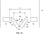
- Another method according to the present disclosure comprises equipping an at least first spray level arrangement 34 with a plurality of downwardly spraying nozzles 40 and an optional second spray level arrangement 36 with a plurality of upwardly spraying nozzles 40, and arranging a plurality of single plates 76 in pairs 77 between the downwardly spraying nozzles 40 outside of the nozzles' 40 spray zones 41 and the upwardly spraying nozzles 46 outside of the nozzles' 40 spray zones 41.
- Each of the single plates 76 of the pairs 77 is arranged with an upstream edge 78 relatively distanced one from the other and a downstream edge 80 in relatively close proximity one to the other. Extending from upstream edge 78 to downstream edge 80 is a plane P/P2.
- the plurality of single plates 76 increases the flue gas FG flow velocity and increases flue gas FG contact with alkaline absorbent liquid/slurry AS/at least partially reacted slurry RS atomised within the wet scrubber tower 16 to generate an increased shear force impact of flue gas FG with alkaline absorbent liquid/slurry AS/at least partially reacted slurry RS.
- This increased shear force impact of flue gas FG with alkaline absorbent liquid/slurry AS/at least partially reacted slurry RS yields very efficient absorption/capture of flue gas FG pollutants, such as sulphur oxides and/or particulate matter.
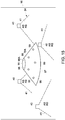
- each of the double plates 82 is arranged with downstream edges 92 relatively distanced one from the other and a common upstream apex 90. Extending from downstream edge 92 to upstream apex 90 are planes P3, P4.
- first portion 88 of double plate 82 has a plane P3 with a positive angle ⁇ + of about 0 degrees to about 60 degrees with respect to horizontal, or about 15 degrees to about 40 degrees with respect to horizontal
- second portion 88A of double plate 82 has a plane P4 with a negative angle ⁇ - of about 0 degrees to about 60 degrees with respect to horizontal, or about 15 degrees to about 40 degrees with respect to horizontal with first portion 88 and second portion 88A joining at common upstream apex 90.
- First portions 88 and second portions 88A may be planar, curved, corrugated, or otherwise formed to achieve desired flue gas FG flow within wet scrubber tower 16. Likewise, first portions 88 and second portions 88A may be square, circular, oblong, or other two-dimensional geometric or non-geometric form to achieve desired flue gas FG flow within wet scrubber tower 16. Further, one or more double plates 82 may include one or more perforations 99 therethrough, such as illustrated in Figure 15 with respect to single plate 76A.
- one single plate 76 has a plane P with a positive angle ⁇ + of about 0 degrees to about 60 degrees with respect to horizontal, or about 15 degrees to about 40 degrees with respect to horizontal, and the other single plate 76 has a plane P2 with a negative angle ⁇ - of about 0 degrees to about 60 degrees with respect to horizontal, or about 15 degrees to about 40 degrees with respect to horizontal.
- Single plates 76 may be planar, curved, corrugated, or otherwise formed to achieve desired flue gas FG flow within wet scrubber tower 16.
- single plates 76 may be square, circular, triangular, oblong, or other two-dimensional geometric or non-geometric form to achieve desired flue gas FG flow within wet scrubber tower 16.
- a single plate 76A may be an open base 97 hollow interior 98 cone, triangular prism, pyramid, or other three-dimensional geometric or non-geometric form to achieve desired flue gas FG flow within wet scrubber tower 16.
- one or more single plates 76A, as well as single plates 76 and double plates 82 may include one or more perforations 99 extending therethrough, such as from exterior surface 96 to interior surface 96A.
- the plurality of double plates 82 are each arranged between the plurality of single plates 76 arranged in pairs 77, just above each downwardly spraying nozzle 40, with a common downstream apex 86 arranged between upstream edges 84.
- each of the double plates 82 is arranged with upstream edges 84 relatively distanced one from the other and a common downstream apex 86. Extending from upstream edge 84 to downstream apex 86 are planes P3, P4.
- first portions 88 and second portions 88A may be square, circular, oblong, or other two-dimensional geometric or non-geometric form to achieve desired flue gas FG flow within wet scrubber tower 16.
- one or more double plates 82 may include one or more perforations 99 therethrough, such as illustrated in Figure 15 with respect to single plate 76A.
- first portion 88 of double plate 82 has a plane P3 with a positive angle ⁇ + of about 0 degrees to about 60 degrees with respect to horizontal, or about 15 degrees to about 40 degrees with respect to horizontal
- second portion 88A of double plate 82 has a plane P4 with a negative angle ⁇ - of about 0 degrees to about 60 degrees with respect to horizontal, or about 15 degrees to about 40 degrees with respect to horizontal with first portion 88 and second portion 88A joining at common downstream apex 86.
- First portions 88 and second portions 88A may be planar, curved, corrugated, or otherwise formed to achieve desired flue gas FG flow within wet scrubber tower 16.
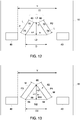
- Illustrated in Figure 12 are nozzles 40 and single plates 76 arranged in pairs 77 therebetween. Between adjacent nozzles 40 is a distance Y. Preferably, the distance D between upstream edges 78 of planar plates 76 is less than Y/2.
- single plates 76 may be square, circular, triangular, oblong, or other two-dimensional geometric or non-geometric form to achieve desired flue gas FG flow within wet scrubber tower 16.
- a single plate 76A may be an open base 97 hollow interior 98 cone, triangular prism, pyramid, or other three-dimensional geometric or non-geometric form to achieve desired flue gas FG flow within wet scrubber tower 16.
- one or more single plates 76A, as well as single plates 76 and double plates 82 may include one or more perforations 99 extending therethrough, such as from exterior surface 96 to interior surface 96A.
Landscapes
- Chemical & Material Sciences (AREA)
- Engineering & Computer Science (AREA)
- Chemical Kinetics & Catalysis (AREA)
- Environmental & Geological Engineering (AREA)
- Analytical Chemistry (AREA)
- General Chemical & Material Sciences (AREA)
- Oil, Petroleum & Natural Gas (AREA)
- Health & Medical Sciences (AREA)
- Biomedical Technology (AREA)
- Mechanical Engineering (AREA)
- General Engineering & Computer Science (AREA)
- Treating Waste Gases (AREA)
Priority Applications (5)
| Application Number | Priority Date | Filing Date | Title |
|---|---|---|---|
| EP17170576.7A EP3401003B1 (en) | 2017-05-11 | 2017-05-11 | Wet scrubber tower with plates between nozzles for wet flue gas desulphurisation and particulate matter removal |
| PL17170576T PL3401003T3 (pl) | 2017-05-11 | 2017-05-11 | Płuczka wieżowa do oczyszczania na mokro z płytami między dyszami do odsiarczania gazów spalinowych i usuwania cząstek stałych metodą mokrą |
| US16/612,503 US10981109B2 (en) | 2017-05-11 | 2018-05-08 | Wet scrubber tower with plates between nozzles for wet flue gas desulphurisation and particulate matter removal |
| KR1020197032276A KR102609704B1 (ko) | 2017-05-11 | 2018-05-08 | 습식 연도 가스 탈황 및 미립자 물질 제거를 위하여 노즐들 사이에 플레이트를 갖는 습식 스크러버 탑 |
| PCT/EP2018/061914 WO2018206599A1 (en) | 2017-05-11 | 2018-05-08 | Wet scrubber tower with plates between nozzles for wet flue gas desulphurisation and particulate matter removal |
Applications Claiming Priority (1)
| Application Number | Priority Date | Filing Date | Title |
|---|---|---|---|
| EP17170576.7A EP3401003B1 (en) | 2017-05-11 | 2017-05-11 | Wet scrubber tower with plates between nozzles for wet flue gas desulphurisation and particulate matter removal |
Publications (2)
| Publication Number | Publication Date |
|---|---|
| EP3401003A1 EP3401003A1 (en) | 2018-11-14 |
| EP3401003B1 true EP3401003B1 (en) | 2020-03-11 |
Family
ID=58707339
Family Applications (1)
| Application Number | Title | Priority Date | Filing Date |
|---|---|---|---|
| EP17170576.7A Active EP3401003B1 (en) | 2017-05-11 | 2017-05-11 | Wet scrubber tower with plates between nozzles for wet flue gas desulphurisation and particulate matter removal |
Country Status (5)
| Country | Link |
|---|---|
| US (1) | US10981109B2 (pl) |
| EP (1) | EP3401003B1 (pl) |
| KR (1) | KR102609704B1 (pl) |
| PL (1) | PL3401003T3 (pl) |
| WO (1) | WO2018206599A1 (pl) |
Families Citing this family (4)
| Publication number | Priority date | Publication date | Assignee | Title |
|---|---|---|---|---|
| EP3437717A1 (en) * | 2017-08-01 | 2019-02-06 | Alfa Laval Corporate AB | A scrubber for cleaning of a gas |
| MY199723A (en) * | 2018-02-09 | 2023-11-20 | Nano Silver Mfg Sdn Bhd | An apparatus for cleaning exhaust smoke |
| CN113905803A (zh) * | 2019-12-04 | 2022-01-07 | 富士电机株式会社 | 废气处理装置 |
| CN120444637B (zh) * | 2025-07-11 | 2025-09-19 | 江苏天兴环保股份有限公司 | 半导体废气处理装置 |
Family Cites Families (10)
| Publication number | Priority date | Publication date | Assignee | Title |
|---|---|---|---|---|
| SE318468B (pl) * | 1966-07-29 | 1969-12-08 | Svenska Flaektfabriken Ab | |
| US3708958A (en) * | 1971-07-19 | 1973-01-09 | C Duty | Device and method for removing pollutants from stack gases |
| US4263021A (en) * | 1972-12-05 | 1981-04-21 | The Babcock & Wilcox Company | Gas-liquid contact system |
| US5246471A (en) * | 1992-02-07 | 1993-09-21 | The Babcock & Wilcox Company | Method and apparatus for gas liquid contact |
| AT402264B (de) * | 1995-09-07 | 1997-03-25 | Austrian Energy & Environment | Verfahren und einrichtung zur nassen abscheidung saurer gase |
| US8128071B2 (en) | 2006-10-03 | 2012-03-06 | Alstom Technology Ltd | Method and apparatus for improved gas/fluid contact |
| PL2361667T3 (pl) * | 2010-02-25 | 2015-07-31 | General Electric Technology Gmbh | Płuczka wodna i sposób oczyszczania gazu procesowego |
| NO335786B1 (no) | 2013-02-22 | 2015-02-16 | Marine Global Holding As | Marin eksosgassrensing |
| CN105879590B (zh) * | 2016-06-03 | 2019-02-01 | 北京国电龙源环保工程有限公司 | 一种旋流式鼓泡耦合高效脱硫喷淋单元及脱硫塔 |
| CN107413176A (zh) * | 2017-09-26 | 2017-12-01 | 航天环境工程有限公司 | 一种氨法脱硫除尘烟气超低排放系统和应用 |
-
2017
- 2017-05-11 PL PL17170576T patent/PL3401003T3/pl unknown
- 2017-05-11 EP EP17170576.7A patent/EP3401003B1/en active Active
-
2018
- 2018-05-08 US US16/612,503 patent/US10981109B2/en active Active
- 2018-05-08 WO PCT/EP2018/061914 patent/WO2018206599A1/en not_active Ceased
- 2018-05-08 KR KR1020197032276A patent/KR102609704B1/ko active Active
Also Published As
| Publication number | Publication date |
|---|---|
| EP3401003A1 (en) | 2018-11-14 |
| PL3401003T3 (pl) | 2020-07-27 |
| US20200197863A1 (en) | 2020-06-25 |
| US10981109B2 (en) | 2021-04-20 |
| KR20200004301A (ko) | 2020-01-13 |
| KR102609704B1 (ko) | 2023-12-04 |
| WO2018206599A1 (en) | 2018-11-15 |
Similar Documents
| Publication | Publication Date | Title |
|---|---|---|
| US9895643B2 (en) | Wet scrubber and a method of cleaning a process gas | |
| EP2361667B1 (en) | A wet scrubber and a method of cleaning a process gas | |
| EP2826541B1 (en) | Wet scrubber nozzle system and method of use for cleaning a process gas | |
| US10981109B2 (en) | Wet scrubber tower with plates between nozzles for wet flue gas desulphurisation and particulate matter removal | |
| KR0156354B1 (ko) | 습식배연탈황장치 | |
| JP2015020169A5 (pl) | ||
| CN102357335A (zh) | 一种切圆式螺旋喷射湿法烟气脱硫装置 | |
| KR102059185B1 (ko) | 습식배연 탈황장치 | |
| CN103894031B (zh) | 文丘里式除雾器 | |
| CN210229598U (zh) | 一种高效率纳米碳酸钙脱硫装置 | |
| CN102000492B (zh) | 喷射石灰浆循环流化床半干法脱硫装置 | |
| US9227157B2 (en) | Spray dryer absorption apparatus with flat-bottomed chamber | |
| CN202237786U (zh) | 一种切圆式螺旋喷射湿法烟气脱硫装置 | |
| CN206793352U (zh) | 用于烟气脱硫系统的吸收塔 | |
| CN112221341A (zh) | 一种用于工业烟气的高效脱硫吸收塔 | |
| JP3483008B2 (ja) | 排煙脱硫装置 | |
| CN1087181C (zh) | 水膜除尘脱硫集成方法及其系统 | |
| CN121891916A (zh) | 可提高脱硫反应充分性的旋转喷雾半干法脱硫塔及方法 | |
| Jack et al. | DEMONSTRATION OF BECHTEL'S CONFINED ZONE DISPERSION PROCESS AT PENNSYLVANIA ELECTRIC COMPANY'S SEWARD STATION PROJECT STATUS |
Legal Events
| Date | Code | Title | Description |
|---|---|---|---|
| PUAI | Public reference made under article 153(3) epc to a published international application that has entered the european phase |
Free format text: ORIGINAL CODE: 0009012 |
|
| STAA | Information on the status of an ep patent application or granted ep patent |
Free format text: STATUS: THE APPLICATION HAS BEEN PUBLISHED |
|
| AK | Designated contracting states |
Kind code of ref document: A1 Designated state(s): AL AT BE BG CH CY CZ DE DK EE ES FI FR GB GR HR HU IE IS IT LI LT LU LV MC MK MT NL NO PL PT RO RS SE SI SK SM TR |
|
| AX | Request for extension of the european patent |
Extension state: BA ME |
|
| STAA | Information on the status of an ep patent application or granted ep patent |
Free format text: STATUS: REQUEST FOR EXAMINATION WAS MADE |
|
| 17P | Request for examination filed |
Effective date: 20190510 |
|
| RBV | Designated contracting states (corrected) |
Designated state(s): AL AT BE BG CH CY CZ DE DK EE ES FI FR GB GR HR HU IE IS IT LI LT LU LV MC MK MT NL NO PL PT RO RS SE SI SK SM TR |
|
| GRAP | Despatch of communication of intention to grant a patent |
Free format text: ORIGINAL CODE: EPIDOSNIGR1 |
|
| STAA | Information on the status of an ep patent application or granted ep patent |
Free format text: STATUS: GRANT OF PATENT IS INTENDED |
|
| RIC1 | Information provided on ipc code assigned before grant |
Ipc: B01D 53/50 20060101AFI20190923BHEP Ipc: B01D 47/06 20060101ALI20190923BHEP Ipc: B01D 47/00 20060101ALI20190923BHEP |
|
| INTG | Intention to grant announced |
Effective date: 20191010 |
|
| GRAS | Grant fee paid |
Free format text: ORIGINAL CODE: EPIDOSNIGR3 |
|
| GRAA | (expected) grant |
Free format text: ORIGINAL CODE: 0009210 |
|
| STAA | Information on the status of an ep patent application or granted ep patent |
Free format text: STATUS: THE PATENT HAS BEEN GRANTED |
|
| AK | Designated contracting states |
Kind code of ref document: B1 Designated state(s): AL AT BE BG CH CY CZ DE DK EE ES FI FR GB GR HR HU IE IS IT LI LT LU LV MC MK MT NL NO PL PT RO RS SE SI SK SM TR |
|
| REG | Reference to a national code |
Ref country code: GB Ref legal event code: FG4D |
|
| REG | Reference to a national code |
Ref country code: CH Ref legal event code: EP |
|
| REG | Reference to a national code |
Ref country code: AT Ref legal event code: REF Ref document number: 1242441 Country of ref document: AT Kind code of ref document: T Effective date: 20200315 |
|
| REG | Reference to a national code |
Ref country code: IE Ref legal event code: FG4D |
|
| REG | Reference to a national code |
Ref country code: DE Ref legal event code: R096 Ref document number: 602017012794 Country of ref document: DE |
|
| PG25 | Lapsed in a contracting state [announced via postgrant information from national office to epo] |
Ref country code: NO Free format text: LAPSE BECAUSE OF FAILURE TO SUBMIT A TRANSLATION OF THE DESCRIPTION OR TO PAY THE FEE WITHIN THE PRESCRIBED TIME-LIMIT Effective date: 20200611 Ref country code: FI Free format text: LAPSE BECAUSE OF FAILURE TO SUBMIT A TRANSLATION OF THE DESCRIPTION OR TO PAY THE FEE WITHIN THE PRESCRIBED TIME-LIMIT Effective date: 20200311 Ref country code: RS Free format text: LAPSE BECAUSE OF FAILURE TO SUBMIT A TRANSLATION OF THE DESCRIPTION OR TO PAY THE FEE WITHIN THE PRESCRIBED TIME-LIMIT Effective date: 20200311 |
|
| REG | Reference to a national code |
Ref country code: NL Ref legal event code: MP Effective date: 20200311 |
|
| PG25 | Lapsed in a contracting state [announced via postgrant information from national office to epo] |
Ref country code: GR Free format text: LAPSE BECAUSE OF FAILURE TO SUBMIT A TRANSLATION OF THE DESCRIPTION OR TO PAY THE FEE WITHIN THE PRESCRIBED TIME-LIMIT Effective date: 20200612 Ref country code: SE Free format text: LAPSE BECAUSE OF FAILURE TO SUBMIT A TRANSLATION OF THE DESCRIPTION OR TO PAY THE FEE WITHIN THE PRESCRIBED TIME-LIMIT Effective date: 20200311 Ref country code: HR Free format text: LAPSE BECAUSE OF FAILURE TO SUBMIT A TRANSLATION OF THE DESCRIPTION OR TO PAY THE FEE WITHIN THE PRESCRIBED TIME-LIMIT Effective date: 20200311 Ref country code: LV Free format text: LAPSE BECAUSE OF FAILURE TO SUBMIT A TRANSLATION OF THE DESCRIPTION OR TO PAY THE FEE WITHIN THE PRESCRIBED TIME-LIMIT Effective date: 20200311 Ref country code: BG Free format text: LAPSE BECAUSE OF FAILURE TO SUBMIT A TRANSLATION OF THE DESCRIPTION OR TO PAY THE FEE WITHIN THE PRESCRIBED TIME-LIMIT Effective date: 20200611 |
|
| REG | Reference to a national code |
Ref country code: LT Ref legal event code: MG4D |
|
| PG25 | Lapsed in a contracting state [announced via postgrant information from national office to epo] |
Ref country code: NL Free format text: LAPSE BECAUSE OF FAILURE TO SUBMIT A TRANSLATION OF THE DESCRIPTION OR TO PAY THE FEE WITHIN THE PRESCRIBED TIME-LIMIT Effective date: 20200311 |
|
| PG25 | Lapsed in a contracting state [announced via postgrant information from national office to epo] |
Ref country code: LT Free format text: LAPSE BECAUSE OF FAILURE TO SUBMIT A TRANSLATION OF THE DESCRIPTION OR TO PAY THE FEE WITHIN THE PRESCRIBED TIME-LIMIT Effective date: 20200311 Ref country code: SM Free format text: LAPSE BECAUSE OF FAILURE TO SUBMIT A TRANSLATION OF THE DESCRIPTION OR TO PAY THE FEE WITHIN THE PRESCRIBED TIME-LIMIT Effective date: 20200311 Ref country code: EE Free format text: LAPSE BECAUSE OF FAILURE TO SUBMIT A TRANSLATION OF THE DESCRIPTION OR TO PAY THE FEE WITHIN THE PRESCRIBED TIME-LIMIT Effective date: 20200311 Ref country code: RO Free format text: LAPSE BECAUSE OF FAILURE TO SUBMIT A TRANSLATION OF THE DESCRIPTION OR TO PAY THE FEE WITHIN THE PRESCRIBED TIME-LIMIT Effective date: 20200311 Ref country code: CZ Free format text: LAPSE BECAUSE OF FAILURE TO SUBMIT A TRANSLATION OF THE DESCRIPTION OR TO PAY THE FEE WITHIN THE PRESCRIBED TIME-LIMIT Effective date: 20200311 Ref country code: SK Free format text: LAPSE BECAUSE OF FAILURE TO SUBMIT A TRANSLATION OF THE DESCRIPTION OR TO PAY THE FEE WITHIN THE PRESCRIBED TIME-LIMIT Effective date: 20200311 Ref country code: IS Free format text: LAPSE BECAUSE OF FAILURE TO SUBMIT A TRANSLATION OF THE DESCRIPTION OR TO PAY THE FEE WITHIN THE PRESCRIBED TIME-LIMIT Effective date: 20200711 Ref country code: PT Free format text: LAPSE BECAUSE OF FAILURE TO SUBMIT A TRANSLATION OF THE DESCRIPTION OR TO PAY THE FEE WITHIN THE PRESCRIBED TIME-LIMIT Effective date: 20200805 |
|
| REG | Reference to a national code |
Ref country code: AT Ref legal event code: MK05 Ref document number: 1242441 Country of ref document: AT Kind code of ref document: T Effective date: 20200311 |
|
| REG | Reference to a national code |
Ref country code: DE Ref legal event code: R097 Ref document number: 602017012794 Country of ref document: DE |
|
| PLBE | No opposition filed within time limit |
Free format text: ORIGINAL CODE: 0009261 |
|
| STAA | Information on the status of an ep patent application or granted ep patent |
Free format text: STATUS: NO OPPOSITION FILED WITHIN TIME LIMIT |
|
| PG25 | Lapsed in a contracting state [announced via postgrant information from national office to epo] |
Ref country code: CH Free format text: LAPSE BECAUSE OF NON-PAYMENT OF DUE FEES Effective date: 20200531 Ref country code: IT Free format text: LAPSE BECAUSE OF FAILURE TO SUBMIT A TRANSLATION OF THE DESCRIPTION OR TO PAY THE FEE WITHIN THE PRESCRIBED TIME-LIMIT Effective date: 20200311 Ref country code: LI Free format text: LAPSE BECAUSE OF NON-PAYMENT OF DUE FEES Effective date: 20200531 Ref country code: ES Free format text: LAPSE BECAUSE OF FAILURE TO SUBMIT A TRANSLATION OF THE DESCRIPTION OR TO PAY THE FEE WITHIN THE PRESCRIBED TIME-LIMIT Effective date: 20200311 Ref country code: AT Free format text: LAPSE BECAUSE OF FAILURE TO SUBMIT A TRANSLATION OF THE DESCRIPTION OR TO PAY THE FEE WITHIN THE PRESCRIBED TIME-LIMIT Effective date: 20200311 Ref country code: DK Free format text: LAPSE BECAUSE OF FAILURE TO SUBMIT A TRANSLATION OF THE DESCRIPTION OR TO PAY THE FEE WITHIN THE PRESCRIBED TIME-LIMIT Effective date: 20200311 Ref country code: MC Free format text: LAPSE BECAUSE OF FAILURE TO SUBMIT A TRANSLATION OF THE DESCRIPTION OR TO PAY THE FEE WITHIN THE PRESCRIBED TIME-LIMIT Effective date: 20200311 |
|
| 26N | No opposition filed |
Effective date: 20201214 |
|
| PG25 | Lapsed in a contracting state [announced via postgrant information from national office to epo] |
Ref country code: SI Free format text: LAPSE BECAUSE OF FAILURE TO SUBMIT A TRANSLATION OF THE DESCRIPTION OR TO PAY THE FEE WITHIN THE PRESCRIBED TIME-LIMIT Effective date: 20200311 |
|
| REG | Reference to a national code |
Ref country code: BE Ref legal event code: MM Effective date: 20200531 |
|
| PG25 | Lapsed in a contracting state [announced via postgrant information from national office to epo] |
Ref country code: LU Free format text: LAPSE BECAUSE OF NON-PAYMENT OF DUE FEES Effective date: 20200511 |
|
| PG25 | Lapsed in a contracting state [announced via postgrant information from national office to epo] |
Ref country code: IE Free format text: LAPSE BECAUSE OF NON-PAYMENT OF DUE FEES Effective date: 20200511 Ref country code: FR Free format text: LAPSE BECAUSE OF NON-PAYMENT OF DUE FEES Effective date: 20200511 |
|
| PG25 | Lapsed in a contracting state [announced via postgrant information from national office to epo] |
Ref country code: BE Free format text: LAPSE BECAUSE OF NON-PAYMENT OF DUE FEES Effective date: 20200531 |
|
| GBPC | Gb: european patent ceased through non-payment of renewal fee |
Effective date: 20210511 |
|
| PG25 | Lapsed in a contracting state [announced via postgrant information from national office to epo] |
Ref country code: GB Free format text: LAPSE BECAUSE OF NON-PAYMENT OF DUE FEES Effective date: 20210511 |
|
| PG25 | Lapsed in a contracting state [announced via postgrant information from national office to epo] |
Ref country code: MT Free format text: LAPSE BECAUSE OF FAILURE TO SUBMIT A TRANSLATION OF THE DESCRIPTION OR TO PAY THE FEE WITHIN THE PRESCRIBED TIME-LIMIT Effective date: 20200311 Ref country code: CY Free format text: LAPSE BECAUSE OF FAILURE TO SUBMIT A TRANSLATION OF THE DESCRIPTION OR TO PAY THE FEE WITHIN THE PRESCRIBED TIME-LIMIT Effective date: 20200311 |
|
| PG25 | Lapsed in a contracting state [announced via postgrant information from national office to epo] |
Ref country code: MK Free format text: LAPSE BECAUSE OF FAILURE TO SUBMIT A TRANSLATION OF THE DESCRIPTION OR TO PAY THE FEE WITHIN THE PRESCRIBED TIME-LIMIT Effective date: 20200311 Ref country code: AL Free format text: LAPSE BECAUSE OF FAILURE TO SUBMIT A TRANSLATION OF THE DESCRIPTION OR TO PAY THE FEE WITHIN THE PRESCRIBED TIME-LIMIT Effective date: 20200311 |
|
| P01 | Opt-out of the competence of the unified patent court (upc) registered |
Effective date: 20230523 |
|
| PGFP | Annual fee paid to national office [announced via postgrant information from national office to epo] |
Ref country code: PL Payment date: 20250423 Year of fee payment: 9 Ref country code: DE Payment date: 20250423 Year of fee payment: 9 |
|
| PGFP | Annual fee paid to national office [announced via postgrant information from national office to epo] |
Ref country code: TR Payment date: 20250429 Year of fee payment: 9 |