EP3400033B1 - Heart pump with impeller axial position control - Google Patents
Heart pump with impeller axial position control Download PDFInfo
- Publication number
- EP3400033B1 EP3400033B1 EP17701386.9A EP17701386A EP3400033B1 EP 3400033 B1 EP3400033 B1 EP 3400033B1 EP 17701386 A EP17701386 A EP 17701386A EP 3400033 B1 EP3400033 B1 EP 3400033B1
- Authority
- EP
- European Patent Office
- Prior art keywords
- impeller
- bearing
- cavity
- axial position
- controller
- Prior art date
- Legal status (The legal status is an assumption and is not a legal conclusion. Google has not performed a legal analysis and makes no representation as to the accuracy of the status listed.)
- Active
Links
Images








Classifications
-
- A—HUMAN NECESSITIES
- A61—MEDICAL OR VETERINARY SCIENCE; HYGIENE
- A61M—DEVICES FOR INTRODUCING MEDIA INTO, OR ONTO, THE BODY; DEVICES FOR TRANSDUCING BODY MEDIA OR FOR TAKING MEDIA FROM THE BODY; DEVICES FOR PRODUCING OR ENDING SLEEP OR STUPOR
- A61M60/00—Blood pumps; Devices for mechanical circulatory actuation; Balloon pumps for circulatory assistance
- A61M60/10—Location thereof with respect to the patient's body
- A61M60/122—Implantable pumps or pumping devices, i.e. the blood being pumped inside the patient's body
- A61M60/165—Implantable pumps or pumping devices, i.e. the blood being pumped inside the patient's body implantable in, on, or around the heart
- A61M60/178—Implantable pumps or pumping devices, i.e. the blood being pumped inside the patient's body implantable in, on, or around the heart drawing blood from a ventricle and returning the blood to the arterial system via a cannula external to the ventricle, e.g. left or right ventricular assist devices
-
- A—HUMAN NECESSITIES
- A61—MEDICAL OR VETERINARY SCIENCE; HYGIENE
- A61M—DEVICES FOR INTRODUCING MEDIA INTO, OR ONTO, THE BODY; DEVICES FOR TRANSDUCING BODY MEDIA OR FOR TAKING MEDIA FROM THE BODY; DEVICES FOR PRODUCING OR ENDING SLEEP OR STUPOR
- A61M60/00—Blood pumps; Devices for mechanical circulatory actuation; Balloon pumps for circulatory assistance
- A61M60/10—Location thereof with respect to the patient's body
- A61M60/122—Implantable pumps or pumping devices, i.e. the blood being pumped inside the patient's body
- A61M60/165—Implantable pumps or pumping devices, i.e. the blood being pumped inside the patient's body implantable in, on, or around the heart
- A61M60/178—Implantable pumps or pumping devices, i.e. the blood being pumped inside the patient's body implantable in, on, or around the heart drawing blood from a ventricle and returning the blood to the arterial system via a cannula external to the ventricle, e.g. left or right ventricular assist devices
- A61M60/183—Implantable pumps or pumping devices, i.e. the blood being pumped inside the patient's body implantable in, on, or around the heart drawing blood from a ventricle and returning the blood to the arterial system via a cannula external to the ventricle, e.g. left or right ventricular assist devices drawing blood from both ventricles, e.g. bi-ventricular assist devices [BiVAD]
-
- A—HUMAN NECESSITIES
- A61—MEDICAL OR VETERINARY SCIENCE; HYGIENE
- A61M—DEVICES FOR INTRODUCING MEDIA INTO, OR ONTO, THE BODY; DEVICES FOR TRANSDUCING BODY MEDIA OR FOR TAKING MEDIA FROM THE BODY; DEVICES FOR PRODUCING OR ENDING SLEEP OR STUPOR
- A61M60/00—Blood pumps; Devices for mechanical circulatory actuation; Balloon pumps for circulatory assistance
- A61M60/10—Location thereof with respect to the patient's body
- A61M60/122—Implantable pumps or pumping devices, i.e. the blood being pumped inside the patient's body
- A61M60/196—Implantable pumps or pumping devices, i.e. the blood being pumped inside the patient's body replacing the entire heart, e.g. total artificial hearts [TAH]
-
- A—HUMAN NECESSITIES
- A61—MEDICAL OR VETERINARY SCIENCE; HYGIENE
- A61M—DEVICES FOR INTRODUCING MEDIA INTO, OR ONTO, THE BODY; DEVICES FOR TRANSDUCING BODY MEDIA OR FOR TAKING MEDIA FROM THE BODY; DEVICES FOR PRODUCING OR ENDING SLEEP OR STUPOR
- A61M60/00—Blood pumps; Devices for mechanical circulatory actuation; Balloon pumps for circulatory assistance
- A61M60/20—Type thereof
- A61M60/205—Non-positive displacement blood pumps
- A61M60/216—Non-positive displacement blood pumps including a rotating member acting on the blood, e.g. impeller
-
- A—HUMAN NECESSITIES
- A61—MEDICAL OR VETERINARY SCIENCE; HYGIENE
- A61M—DEVICES FOR INTRODUCING MEDIA INTO, OR ONTO, THE BODY; DEVICES FOR TRANSDUCING BODY MEDIA OR FOR TAKING MEDIA FROM THE BODY; DEVICES FOR PRODUCING OR ENDING SLEEP OR STUPOR
- A61M60/00—Blood pumps; Devices for mechanical circulatory actuation; Balloon pumps for circulatory assistance
- A61M60/20—Type thereof
- A61M60/205—Non-positive displacement blood pumps
- A61M60/216—Non-positive displacement blood pumps including a rotating member acting on the blood, e.g. impeller
- A61M60/226—Non-positive displacement blood pumps including a rotating member acting on the blood, e.g. impeller the blood flow through the rotating member having mainly radial components
- A61M60/232—Centrifugal pumps
-
- A—HUMAN NECESSITIES
- A61—MEDICAL OR VETERINARY SCIENCE; HYGIENE
- A61M—DEVICES FOR INTRODUCING MEDIA INTO, OR ONTO, THE BODY; DEVICES FOR TRANSDUCING BODY MEDIA OR FOR TAKING MEDIA FROM THE BODY; DEVICES FOR PRODUCING OR ENDING SLEEP OR STUPOR
- A61M60/00—Blood pumps; Devices for mechanical circulatory actuation; Balloon pumps for circulatory assistance
- A61M60/40—Details relating to driving
- A61M60/403—Details relating to driving for non-positive displacement blood pumps
- A61M60/419—Details relating to driving for non-positive displacement blood pumps the force acting on the blood contacting member being permanent magnetic, e.g. from a rotating magnetic coupling between driving and driven magnets
-
- A—HUMAN NECESSITIES
- A61—MEDICAL OR VETERINARY SCIENCE; HYGIENE
- A61M—DEVICES FOR INTRODUCING MEDIA INTO, OR ONTO, THE BODY; DEVICES FOR TRANSDUCING BODY MEDIA OR FOR TAKING MEDIA FROM THE BODY; DEVICES FOR PRODUCING OR ENDING SLEEP OR STUPOR
- A61M60/00—Blood pumps; Devices for mechanical circulatory actuation; Balloon pumps for circulatory assistance
- A61M60/40—Details relating to driving
- A61M60/403—Details relating to driving for non-positive displacement blood pumps
- A61M60/422—Details relating to driving for non-positive displacement blood pumps the force acting on the blood contacting member being electromagnetic, e.g. using canned motor pumps
-
- A—HUMAN NECESSITIES
- A61—MEDICAL OR VETERINARY SCIENCE; HYGIENE
- A61M—DEVICES FOR INTRODUCING MEDIA INTO, OR ONTO, THE BODY; DEVICES FOR TRANSDUCING BODY MEDIA OR FOR TAKING MEDIA FROM THE BODY; DEVICES FOR PRODUCING OR ENDING SLEEP OR STUPOR
- A61M60/00—Blood pumps; Devices for mechanical circulatory actuation; Balloon pumps for circulatory assistance
- A61M60/80—Constructional details other than related to driving
- A61M60/802—Constructional details other than related to driving of non-positive displacement blood pumps
- A61M60/804—Impellers
-
- A—HUMAN NECESSITIES
- A61—MEDICAL OR VETERINARY SCIENCE; HYGIENE
- A61M—DEVICES FOR INTRODUCING MEDIA INTO, OR ONTO, THE BODY; DEVICES FOR TRANSDUCING BODY MEDIA OR FOR TAKING MEDIA FROM THE BODY; DEVICES FOR PRODUCING OR ENDING SLEEP OR STUPOR
- A61M60/00—Blood pumps; Devices for mechanical circulatory actuation; Balloon pumps for circulatory assistance
- A61M60/80—Constructional details other than related to driving
- A61M60/802—Constructional details other than related to driving of non-positive displacement blood pumps
- A61M60/804—Impellers
- A61M60/806—Vanes or blades
-
- A—HUMAN NECESSITIES
- A61—MEDICAL OR VETERINARY SCIENCE; HYGIENE
- A61M—DEVICES FOR INTRODUCING MEDIA INTO, OR ONTO, THE BODY; DEVICES FOR TRANSDUCING BODY MEDIA OR FOR TAKING MEDIA FROM THE BODY; DEVICES FOR PRODUCING OR ENDING SLEEP OR STUPOR
- A61M60/00—Blood pumps; Devices for mechanical circulatory actuation; Balloon pumps for circulatory assistance
- A61M60/80—Constructional details other than related to driving
- A61M60/802—Constructional details other than related to driving of non-positive displacement blood pumps
- A61M60/81—Pump housings
- A61M60/814—Volutes
-
- A—HUMAN NECESSITIES
- A61—MEDICAL OR VETERINARY SCIENCE; HYGIENE
- A61M—DEVICES FOR INTRODUCING MEDIA INTO, OR ONTO, THE BODY; DEVICES FOR TRANSDUCING BODY MEDIA OR FOR TAKING MEDIA FROM THE BODY; DEVICES FOR PRODUCING OR ENDING SLEEP OR STUPOR
- A61M60/00—Blood pumps; Devices for mechanical circulatory actuation; Balloon pumps for circulatory assistance
- A61M60/80—Constructional details other than related to driving
- A61M60/802—Constructional details other than related to driving of non-positive displacement blood pumps
- A61M60/81—Pump housings
- A61M60/816—Sensors arranged on or in the housing, e.g. ultrasonic flow sensors
-
- A—HUMAN NECESSITIES
- A61—MEDICAL OR VETERINARY SCIENCE; HYGIENE
- A61M—DEVICES FOR INTRODUCING MEDIA INTO, OR ONTO, THE BODY; DEVICES FOR TRANSDUCING BODY MEDIA OR FOR TAKING MEDIA FROM THE BODY; DEVICES FOR PRODUCING OR ENDING SLEEP OR STUPOR
- A61M60/00—Blood pumps; Devices for mechanical circulatory actuation; Balloon pumps for circulatory assistance
- A61M60/80—Constructional details other than related to driving
- A61M60/802—Constructional details other than related to driving of non-positive displacement blood pumps
- A61M60/818—Bearings
- A61M60/82—Magnetic bearings
- A61M60/822—Magnetic bearings specially adapted for being actively controlled
-
- A—HUMAN NECESSITIES
- A61—MEDICAL OR VETERINARY SCIENCE; HYGIENE
- A61M—DEVICES FOR INTRODUCING MEDIA INTO, OR ONTO, THE BODY; DEVICES FOR TRANSDUCING BODY MEDIA OR FOR TAKING MEDIA FROM THE BODY; DEVICES FOR PRODUCING OR ENDING SLEEP OR STUPOR
- A61M60/00—Blood pumps; Devices for mechanical circulatory actuation; Balloon pumps for circulatory assistance
- A61M60/80—Constructional details other than related to driving
- A61M60/802—Constructional details other than related to driving of non-positive displacement blood pumps
- A61M60/818—Bearings
- A61M60/824—Hydrodynamic or fluid film bearings
-
- F—MECHANICAL ENGINEERING; LIGHTING; HEATING; WEAPONS; BLASTING
- F04—POSITIVE - DISPLACEMENT MACHINES FOR LIQUIDS; PUMPS FOR LIQUIDS OR ELASTIC FLUIDS
- F04D—NON-POSITIVE-DISPLACEMENT PUMPS
- F04D29/00—Details, component parts, or accessories
- F04D29/04—Shafts or bearings, or assemblies thereof
- F04D29/046—Bearings
- F04D29/048—Bearings magnetic; electromagnetic
-
- F—MECHANICAL ENGINEERING; LIGHTING; HEATING; WEAPONS; BLASTING
- F04—POSITIVE - DISPLACEMENT MACHINES FOR LIQUIDS; PUMPS FOR LIQUIDS OR ELASTIC FLUIDS
- F04D—NON-POSITIVE-DISPLACEMENT PUMPS
- F04D29/00—Details, component parts, or accessories
- F04D29/18—Rotors
- F04D29/22—Rotors specially for centrifugal pumps
- F04D29/24—Vanes
- F04D29/242—Geometry, shape
-
- F—MECHANICAL ENGINEERING; LIGHTING; HEATING; WEAPONS; BLASTING
- F04—POSITIVE - DISPLACEMENT MACHINES FOR LIQUIDS; PUMPS FOR LIQUIDS OR ELASTIC FLUIDS
- F04D—NON-POSITIVE-DISPLACEMENT PUMPS
- F04D29/00—Details, component parts, or accessories
- F04D29/40—Casings; Connections of working fluid
- F04D29/42—Casings; Connections of working fluid for radial or helico-centrifugal pumps
- F04D29/426—Casings; Connections of working fluid for radial or helico-centrifugal pumps especially adapted for liquid pumps
- F04D29/4293—Details of fluid inlet or outlet
-
- A—HUMAN NECESSITIES
- A61—MEDICAL OR VETERINARY SCIENCE; HYGIENE
- A61M—DEVICES FOR INTRODUCING MEDIA INTO, OR ONTO, THE BODY; DEVICES FOR TRANSDUCING BODY MEDIA OR FOR TAKING MEDIA FROM THE BODY; DEVICES FOR PRODUCING OR ENDING SLEEP OR STUPOR
- A61M2205/00—General characteristics of the apparatus
- A61M2205/33—Controlling, regulating or measuring
- A61M2205/3331—Pressure; Flow
- A61M2205/3334—Measuring or controlling the flow rate
-
- A—HUMAN NECESSITIES
- A61—MEDICAL OR VETERINARY SCIENCE; HYGIENE
- A61M—DEVICES FOR INTRODUCING MEDIA INTO, OR ONTO, THE BODY; DEVICES FOR TRANSDUCING BODY MEDIA OR FOR TAKING MEDIA FROM THE BODY; DEVICES FOR PRODUCING OR ENDING SLEEP OR STUPOR
- A61M2205/00—General characteristics of the apparatus
- A61M2205/33—Controlling, regulating or measuring
- A61M2205/3365—Rotational speed
-
- A—HUMAN NECESSITIES
- A61—MEDICAL OR VETERINARY SCIENCE; HYGIENE
- A61M—DEVICES FOR INTRODUCING MEDIA INTO, OR ONTO, THE BODY; DEVICES FOR TRANSDUCING BODY MEDIA OR FOR TAKING MEDIA FROM THE BODY; DEVICES FOR PRODUCING OR ENDING SLEEP OR STUPOR
- A61M2206/00—Characteristics of a physical parameter; associated device therefor
- A61M2206/10—Flow characteristics
- A61M2206/14—Static flow deviators in tubes disturbing laminar flow in tubes, e.g. archimedes screws
-
- A—HUMAN NECESSITIES
- A61—MEDICAL OR VETERINARY SCIENCE; HYGIENE
- A61M—DEVICES FOR INTRODUCING MEDIA INTO, OR ONTO, THE BODY; DEVICES FOR TRANSDUCING BODY MEDIA OR FOR TAKING MEDIA FROM THE BODY; DEVICES FOR PRODUCING OR ENDING SLEEP OR STUPOR
- A61M2206/00—Characteristics of a physical parameter; associated device therefor
- A61M2206/10—Flow characteristics
- A61M2206/20—Flow characteristics having means for promoting or enhancing the flow, actively or passively
-
- A—HUMAN NECESSITIES
- A61—MEDICAL OR VETERINARY SCIENCE; HYGIENE
- A61M—DEVICES FOR INTRODUCING MEDIA INTO, OR ONTO, THE BODY; DEVICES FOR TRANSDUCING BODY MEDIA OR FOR TAKING MEDIA FROM THE BODY; DEVICES FOR PRODUCING OR ENDING SLEEP OR STUPOR
- A61M2230/00—Measuring parameters of the user
- A61M2230/04—Heartbeat characteristics, e.g. ECG, blood pressure modulation
-
- A—HUMAN NECESSITIES
- A61—MEDICAL OR VETERINARY SCIENCE; HYGIENE
- A61M—DEVICES FOR INTRODUCING MEDIA INTO, OR ONTO, THE BODY; DEVICES FOR TRANSDUCING BODY MEDIA OR FOR TAKING MEDIA FROM THE BODY; DEVICES FOR PRODUCING OR ENDING SLEEP OR STUPOR
- A61M2230/00—Measuring parameters of the user
- A61M2230/30—Blood pressure
-
- A—HUMAN NECESSITIES
- A61—MEDICAL OR VETERINARY SCIENCE; HYGIENE
- A61M—DEVICES FOR INTRODUCING MEDIA INTO, OR ONTO, THE BODY; DEVICES FOR TRANSDUCING BODY MEDIA OR FOR TAKING MEDIA FROM THE BODY; DEVICES FOR PRODUCING OR ENDING SLEEP OR STUPOR
- A61M60/00—Blood pumps; Devices for mechanical circulatory actuation; Balloon pumps for circulatory assistance
- A61M60/10—Location thereof with respect to the patient's body
- A61M60/122—Implantable pumps or pumping devices, i.e. the blood being pumped inside the patient's body
- A61M60/126—Implantable pumps or pumping devices, i.e. the blood being pumped inside the patient's body implantable via, into, inside, in line, branching on, or around a blood vessel
- A61M60/148—Implantable pumps or pumping devices, i.e. the blood being pumped inside the patient's body implantable via, into, inside, in line, branching on, or around a blood vessel in line with a blood vessel using resection or like techniques, e.g. permanent endovascular heart assist devices
-
- F—MECHANICAL ENGINEERING; LIGHTING; HEATING; WEAPONS; BLASTING
- F04—POSITIVE - DISPLACEMENT MACHINES FOR LIQUIDS; PUMPS FOR LIQUIDS OR ELASTIC FLUIDS
- F04D—NON-POSITIVE-DISPLACEMENT PUMPS
- F04D1/00—Radial-flow pumps, e.g. centrifugal pumps; Helico-centrifugal pumps
Definitions
- the present invention relates to a heart pump and a controller for a heart pump controlling an axial position of an impeller in a heart pump.
- US-8,636,638 describes a controller for a heart pump that determines movement of an impeller within a cavity in a first axial direction, the cavity including at least one inlet and at least one outlet, and the impeller including vanes for urging fluid from the inlet to the outlet, causing a magnetic bearing to move the impeller in a second axial direction opposite the first axial direction, the magnetic bearing including at least one coil for controlling an axial position of the impeller within the cavity, determining an indicator indicative of the power used by the magnetic bearing and causing the magnetic bearing to control the axial position of the impeller in accordance with the indicator to thereby control a fluid flow between the inlet and the outlet.
- US-7,435,059 describes a system for pumping blood to assist or assume the cardiac function of a patient is characterized by a blood pump that exhibits a steep pump curve such that only small changes in pump flow occur for large changes in differential pressure across the pump.
- the pump therefore exhibits flow-limiting characteristics to protect the physiological system against harmful flow rates.
- Pump flow may also be limited by controlling the current provided to a driver from a power supply or by suitable restrictions within or external to the pump housing.
- This arrangement provides a so called zero power configuration that attempts to minimise the power required by the magnetic bearing used to suspend the rotor. However, this does not provide adequate control of impeller position in all scenarios.
- the heart pump is a biventricular device, which can operate either as a ventricular assist device to assist function of left and right ventricles of a subject's heart, or alternatively as a total artificial heart. It will be appreciated however that whilst reference is made to a biventricular device this is not essential, and alternatively the control processes described herein could equally be applied to single ventricular assist devices or any other form of blood pump.
- the heart pump 100 includes a housing 110 defining a cavity 115.
- the housing can be of any suitable form but typically includes a main body 110.1, left and right end caps 110.2, 110.3 which connect to the main body 110.1, as well as an end plate 110.4 positioned between the main body 110.1 and left end cap 110.2.
- the housing can be made of any suitable biocompatible material, and can be made of titanium, a polymer or the like.
- the housing 110 includes two inlets 111, 113, for connection to the left atrium/pulmonary vein and right atrium/vena cava, or left and right ventricles, and two outlets 112, 114 for connection to the aorta and pulmonary artery, respectively. Whilst two inlets and outlets are shown, it will be appreciated that this is in the context of a biventricular device, and that a single inlet and outlet can be used for a single ventricular device.
- the heart pump 100 includes an impeller 120 provided within the cavity 115.
- the impeller 120 includes a rotor 121 having vanes mounted thereon for urging fluid from the inlet to the outlet upon rotation of the impeller 120.
- the impeller includes two sets of vanes 122, 123 each of which is used for urging fluid from a respective inlet 111, 113 to a respective outlet 112, 114.
- the rotor 121 is positioned within the cavity 115 to effectively divide the cavity into first and second cavity portions, each having a respective inlet and outlet, thereby allowing each to function as a respective pump.
- the vanes 122 are used to urge fluid from the inlet 111 to the outlet 112, with this being provided on the left-hand side of the pump in the orientation shown in Figure 1B , and operating to provide left-ventricular function, whilst the vanes 123 urge fluid from the inlet 113 to the outlet 114 and act to provide right-ventricular function.
- the first and second cavity portions are generally referred to as left and right cavities, respectively. It will be appreciated that in this regard, the terms left and right refer to the intended ventricular function of the cavities as opposed to the particular orientation of the pump in Figures 1B , which is used for illustrative purposes only.
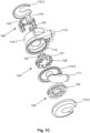
- the heart pump 100 further includes a drive 130 that rotates the impeller 120 within the cavity 115.
- the drive 130 can be of any appropriate form but typically includes a number of coils 131 wound on a stator 132, supported by a mounting 133, allowing the drive 130 to be coupled to the housing 110.
- the drive cooperates with magnetic material 134 mounted in the rotor 121 with this typically being in the form of a number of circumferentially spaced permanent magnets mounted in the rotor 121 proximate an outer circumferential edge of the rotor and proximate a face of the rotor facing the drive coils 131.
- the coils 131 and stators 132 are wedge shaped and circumferentially spaced around the mounting 133, so as to provide twelve electromagnets radially aligned with circumferentially spaced drive magnets 134 in the rotor 121, to thereby maximise a degree of magnetic coupling between the magnets in the rotor 121 and the drive 130.
- the drive magnets 134 are typically arcuate shaped rare earth magnets, circumferentially spaced proximate an outer circumferential edge of the rotor 121, and mounted on a soft iron rotor drive yoke.
- the heart pump 100 can further include a magnetic bearing 140 including at least one bearing coil 141 which cooperates with bearing magnetic material mounted in the rotor 121 to thereby control an axial position of the impeller 120 within the cavity 115.
- the magnetic bearing includes three bearing coils 141, each of which is mounted on a first leg 142.1 of respective U-shaped stators 142, with a second leg 142.2 being positioned radially inwardly of the first leg 142.1.
- the stators 142 are mounted to a support 143 and circumferentially spaced 120° apart around the housing so that the first and second legs 1421. 142.2 align with respective bearing magnetic material, such as bearing magnets 144, 145, optionally mounted on a common yoke (not shown) allowing an axial position of the impeller 120 to be controlled.
- the bearing magnetic material typically includes first and second annular magnetic bearing members mounted within and proximate a face of the rotor facing the bearing coils 141, the first magnetic bearing member being provided radially outwardly of the second magnetic bearing member.
- the first bearing magnet material 144 includes an annular soft iron material that can be integrally formed with the annular yoke, or an annular permanent magnet 144 mounted on the yoke, and mounted in the rotor, proximate an outer circumferential edge of the rotor 121.
- the second bearing magnetic material is an annular permanent bearing magnet 145 mounted radially inwardly of the first bearing member 144, so that the first and second bearing members 144, 145 align with respective legs 142.1, 142.2 of the stators 142.
- annular members could include a plurality of individual elements, such as individual circumferentially spaced magnets or ferromagnetic elements. Additionally, the use of a magnetic bearing may not be required and can be replaced by a static physical bearing, or the like.
- the drive 130 and magnetic bearing 140 are mounted at opposing ends of the housing 110 so that the drive and bearing 130, 140 are provided proximate opposing surfaces of the rotor 121 as shown for example in Figure 1D , and Figures 2G, 2H, 2J and 2K.
- the drive 130 is mounted adjacent the left pump, whilst the bearing 140 is mounted adjacent the right pump, although the opposite configuration is contemplated.
- the depicted arrangement has a number of benefits.
- the inherent attractive magnetic forces between the drive and rotor and the bearing and rotor can be configured to substantially balance when the rotor is provided at a balance point at a normal operating speed, which may for example by approximately at a center of the cavity under conditions of normal flow.
- this arrangement can be configured so that the magnetic forces inherent between the drive 130 and impeller 120, and between the magnetic bearing 140 and impeller 120 are matched at an impeller balance position within the cavity, which corresponds to a desired position of the impeller under conditions of normal flow. This minimises the bearing current required to maintain the position of the impeller 120 within the cavity, hence reducing the amount power required to operate, and in particular drive and axially position the impeller.
- the forces generated by the drive and bearing can also be configured to provide a desired degree of axial and radial stiffness.
- the stiffness is a measure of the deflection of the impeller 120 from a balance position in response to an external force. In one example, it is desirable to maximise the radial stiffness so as to maintain the impeller radially centralised within the cavity and to stop the impeller touching the inner circumferential wall of the cavity.
- the axial position of the impeller 120 can be used for flow control, and in particular to allow for passive and/or active response to changes in hemodynamic parameters, a low degree of axial stiffness is preferred. Accordingly, the passive magnetic forces can be configured to assist in meeting these requirements, as will be described in more detail below.
- a further benefit of the above described arrangement in the context of BiVAD applications, is that it allows the greater size of the magnetic bearing to be accommodated by the smaller size of the right pump cavity.
- this allows a gap between a bearing stator and bearing magnets to be minimized, as no vanes are located in this gap (as opposed to the left side where vanes are located in the magnetic airgap between the drive and the rotor), as will be described in more detail below.
- the apparatus further includes a controller 150 which, in use, is coupled to a sensor 160 and the drive and bearing coils 131, 141.
- the sensor 160 senses an axial position of the impeller 120 within the cavity 115 and can be of appropriate form such as a reluctance or eddy current sensor, which detect magnetic fields within the rotor 121 to thereby determine a separation between the rotor and the sensor 160, as will be appreciated by persons skilled in the art.
- each sensor would typically include a coil mounted in a housing, circumferentially spaced and aligned with the inner leg 142.2 of the magnetic bearing stators 142.
- the coil is aligned with a rotor shell/target mounted radially inwardly of a first bearing magnet 144, so as to generate a field therein, with variations in the field being detected to determine the separation of the sensor 160 and the shell/target, and hence the rotor 121.
- suitable sensors can be used, such as reluctance sensors or the like, in which case the first permanent magnet 144 might be replaced with ferromagnetic material, depending on the sensor/bearing requirements.
- controller 150 is adapted to monitor signals from the position sensor 160 and then control the current supplied to the drive coils 131 to control rotation of the impeller and to the bearing coils 141 to control the axial position of the impeller 120.
- the controller 150 can be of any suitable form but typically includes an electronic processing device 151, an optional memory 152, and an interface 154 for connecting to the heart pump, each of which are interconnected by a bus 155, or other similar arrangement.
- the electronic processing device can be any form of electronic processing device capable of interpreting signals and causing the drive and bearing to be controlled, such as a microprocessor, microchip processor, logic gate configuration, firmware optionally associated with implementing logic such as an FPGA (Field Programmable Gate Array), or any other electronic device, system or arrangement.
- An optional external interface 153 may be provided allowing for interaction with the controller 150.
- this could include an I/O device 153 such as a touch screen or the like, whereas if positioned inside the body this would typically be in the form of a wireless communications module allowing communication with an external control device.
- the impeller 120 when operating under normal conditions, the impeller 120 is magnetically suspended within the cavity 115, with hydraulic forces acting on the impeller 120 due to fluid pressure within each of the left and right cavities and magnetic forces generated by the drive 130 and bearing 140 being substantially balanced.
- the impeller 120 is typically suspended at a reference position within the cavity, sometimes referred to as a central position.
- a pressure change occurs within one or both of the left or right cavities.
- the pressure change would typically occur as a result of a physiological change within the subject which could arise for any one of a number of reasons, such as the subject moving, commencing exercise, or the like.
- the pressure change will generally result in a change in the hydraulic forces acting on the impeller 120 resulting in a net force towards the left or right cavity for the current bearing settings.
- the controller 150 determines the axial position of the impeller 120, and uses this to determine a reference power at step 220.
- the reference power is defined as a function of impeller position, with the reference power varying based on a distance of the impeller from the notional central position with the cavity.
- the controller 150 moves the impeller by controlling the magnetic bearing 140 to cause the impeller 120 to move until a bearing power indicator indicative of the power used by the magnetic bearing reaches the reference power.
- the bearing power indicator can be of any appropriate form, but in one example is indicative of or derived from the bearing current drawn by the magnetic bearing, for example based on a filtered version of the raw current signals, with the reference power corresponding to a respective current value. However, it will be appreciated that this is not essential, and any suitable bearing power indicator and corresponding type of reference values can be used.
- the reference power is defined as a function of the axial position of the impeller within the cavity. Accordingly, as the impeller moves within the cavity, the controller 150 repeats steps 210 to 230, determining a new reference power based on the new axial position of the impeller 120, using this to control further movement of the impeller 120.
- the reference power determined by the controller increases as the impeller 120 moves away from the notational centre point within the cavity. The effect of this is that when compared to a traditional zero-power control process, additional movement of the impeller is induced.
- the further movement will typically include moving the impeller further towards the left cavity, in effect amplifying the movement induced by the zero-power control approach.
- the reason for performing additional movement control is to amplify changes in fluid flow between the inlet(s) and outlet(s).
- movement of the impeller has an impact on the efficiency of the pump, with a reduction in separation between the vanes 122, 123 and cavity leading to an increase in pump efficiency. Accordingly, moving the impeller 120 within the cavity 115 can be used to increase or decrease pump flow.
- moving the impeller can be used to increase or decrease flow.
- this can increase/decrease one pump output, whilst simultaneously decreasing/increasing the other pump output, which is particularly useful in balancing fluid pressures between the left and right cavities, and hence within the systemic and pulmonary circulatory systems in the subject.
- a decrease in left-ventricular pressure requires an increase in blood flow through the left ventricle in order to return pressure to normal levels. Accordingly, this can be achieved by moving the impeller towards the left cavity, increasing the effectiveness of left ventricular function.
- the degree of axial movement of the impeller 120 within the cavity 115 will naturally vary depending on the axial stiffness of the magnetic bearing arrangement.
- a relatively weak stiffness will result in a higher degree of axial movement for a given pressure change, which in turn can enhance the effectiveness of the ability of the heart pump to correct pressure imbalances, for example between the left and right sides.
- a magnetic bearing with a high degree of stiffness will result in a relatively small amount of axial movement for a given pressure change, meaning the effectiveness to correct pressure imbalances in reduced.
- the axial stiffness of the magnetic bearing is dependent on the degree of magnetic coupling between the bearing 140 and impeller 120, which in turn also affects the radial stiffness, meaning an axially weak magnetic bearing is also radially weak, which in turn allows for radial movement of the impeller within the cavity.
- Such radial movement is undesirable as this can lead to contact between the rotor 121 and an inner wall of the cavity 115, which can cause damage to the pump.
- a small separation between the rotor 121 and cavity wall can lead to high shear stresses, which in turn can case rupturing of blood platelets leading to hemolysis.
- a magnetic bearing that has significant radial stiffness, so as to restrict radial movement of the impeller, but which at least mimics the effect of an axially weak bearing.
- This can be achieved through the utilisation of the above described control process which uses a physically strong axial magnetic bearing, and hence a radially strong bearing, but implements additional control processes in order to simulate the effect of an axially weak bearing.
- This assists in providing a magnetic bearing that allows the pump to respond to pressure changes within the cavities to balance flows, whilst preventing radial movement of the impeller.
- the techniques described herein can be conversely used to increase the effective axial stiffness, which can be used to avoid the impeller reaching an extreme axial position within the cavity, as will be described in more detail below.
- control process operates to move the impeller in a direction opposite a net force induced on the impeller. Accordingly, when the change in hydraulic forces generates a resultant force acting on the impeller in a first axial direction, the controller controls the magnetic bearing to move the impeller in the second axial direction opposite to the first axial direction. Thus, an increase in pressure in the left cavity will cause the impeller to be moved towards the left cavity.
- the controller 150 can determine changes in axial hydraulic forces within the cavity either by detecting axial movement of the impeller within the cavity, for example by detecting movement in the first direction, or by detecting changes in the bearing power indicator required to maintain the impeller at a constant axial position within the cavity.
- the technique used will vary depending upon the preferred control implementation.
- the controller 150 can implement a bearing control process which operates to adjust the power used by the magnetic bearing 140 in order to maintain the impeller 120 at a constant position, in which case changes in bearing power will be used to determine the net forces, whereas alternatively the controller 140 could attempt to maintain a constant power, in which case movement of the impeller 120 would be detected.
- the controller determines changes in axial hydraulic forces by filtering a bearing current signal using a low pass filter.
- the low pass filter can have a cut-off of at least one of: between 0.1-10Hz, between 1-15Hz; between 15-30Hz; approximately 15Hz; approximately 30Hz; approximately 1Hz; and, between 30-100Hz.
- the controller 150 operates to iteratively move the impeller 120 by repeatedly controlling the magnetic bearing to move the impeller 120 to a new axial position in accordance with the reference power, then modifying the reference power in accordance with the new axial position of the impeller. This process can be repeated until a desired end point is reached. This can be performed on the basis of a set number of iterations but more typically is performed until the modified reference power reaches a defined threshold value, the axial position reaches a defined threshold or the hydraulic forces are either balanced or overcome. Thus, it will be appreciated that this process can continue until the impeller 120 reaches a maximum extreme position within the cavity 115, for example corresponding to a distance of minimum separation from the cavity wall, or until the hydraulic forces are again balanced.
- the operating range of the impeller is restricted to +/-200 ⁇ m when operating in a total 0.6mm clearance, so as to not allow the impeller to come with 100 ⁇ m of the stationary housing to assist with hemocompatibility.
- the rotor may be able to come within 50 ⁇ m of the stationary casing at critical times to assist with flow balancing, effectively expanding the range of movement to +/-250 ⁇ m. It would be appreciated that these limits from the housing are fixed, resulting in a larger operating range as total clearance gap increases.
- the impeller can't move any further so additional changes in forces acting on the impeller must be counteracted solely by changes in the magnetic forces generated by the bearing and hence the bearing current used, and not the usual control of changes in bearing current and impeller position. This can lead to excessive changes in bearing current, which can in turn impact on other control processes, such as the detection of characteristic force events or control of impeller rotational speed, described for example in copending application USSN 62/275723 .
- the above described control process can be used to alter the effective stiffness of the system different for different regions of the operational range. For example, as the impeller gets closer to a positional limit, the controller can be used to increase the effective axial stiffness of the bearing, which would mean that a further increase of the forces would result in a smaller axial movement.
- the system can have a dynamic effective axial stiffness based on the impeller position, so that in a central region of the cavity, the impeller can have a low axial stiffness to provide maximum axial and hence hemodynamic responsiveness.
- the stiffness can be increased to thereby reduce the axial responsiveness, thereby avoiding the impeller passing beyond limits and impacting on the housing, whilst also reducing the likelihood of current peaks or spikes impacting on other control algorithms or resulting in excess power use.
- the impeller position can be controlled on the basis of a first limit and a second limit, with the first limit defining a preferred impeller position range and the second limit defining a maximum impeller position range.
- the first limit can provide a soft limit, which is a notionally preferred limit to the axial position, as compared to a hard limit defined by the second limit, which is an axial position beyond which there is a risk of the impeller contacting the housing.
- the controller 150 typically determines the reference power by progressively increasing a magnitude of the reference power by a progressively smaller amount for each iteration, such that the degree of movement reduces on each iteration as the impeller 120 moves away from the zero-power reference position. This allows the impeller to be moved asymptotically towards a new balance position, in particular allowing for initial rapid coarse correction, with fine correction being implemented as the impeller reaches a new balance position.
- any function relating the reference power to the axial position of the impeller within the housing can be used, for example to reduce the amount of movement when compared to the traditional zero power configuration, thereby providing a bearing that is effectively axially stiffer.
- the controller 150 controls the magnetic bearing to cause the impeller 120 to move to a target axial position.
- the controller 150 determines if the bearing power indicator is at the reference power at the target positon, and if not, determines a new target axial position of the impeller, determines a reference power in accordance with the new axial position and uses the reference power to determine a new target axial position. This process can then be repeated providing a positive feedback loop, until such time as the bearing power indicator reaches the reference power, when at the current defined target position.
- the controller 150 includes a bearing controller that uses signals from the position sensor 160 to determine the current axial position of the impeller 120, controls the current supplied to the magnetic bearing to thereby maintain the impeller 120 at a target axial position and outputs an indication of the bearing power indicator and current axial position.
- the controller 150 then further includes a position controller that uses the bearing power indicator and current axial position to determine a target axial position which is then provided to the bearing controller.
- the bearing and position controllers could include physically separate hardware, but more typically are logically separate control processes implemented on a common processing device, as will be described in more detail below.
- the position controller can include a first controller that calculates a reference power using the current axial position of the impeller and a second controller that determines the target axial position using the reference power and the bearing power indicator. Additional details of the control arrangement will be described in more detail below.
- the controller 150 can also operate to record an indication of the bearing power indicator and such or the current axial position allowing this to be reviewed, for example for logging purposes.
- the above described processes allow a heart pump to be implemented with a magnetic bearing system having a high degree of axial stiffness, whilst maintaining a degree of control over flow balance typically only achievable with a low stiffness bearing configuration.
- bearing current is used as an indicator of bearing power, but it will be appreciated that this is not intended to be limiting in the context of the application as a whole.
- the controller 150 monitors a position sensor 160 and determines if the impeller 120 is at a target position at step 310. Under nominal flow conditions (referred to as balanced conditions), the impeller 120 is provided at an initial reference position RP, with the bearing current IB remaining substantially constant at a reference level IB ref , as shown in Figure 4A . If there is no impeller movement, and the impeller is at the target position, the process returns to step 300, allowing the position to be monitored in an ongoing process.
- balanced conditions referred to as balanced conditions
- the controller 150 will adjust the bearing power to maintain the impeller 120 at the target impeller position, initially corresponding to the reference position RP.
- an increase in left ventricular pressure leads to a net hydraulic force towards the right cavity, as shown by the arrow F H , which initially causes movement of the impeller to the right cavity.
- the controller 150 adjusts the current used by the magnetic bearing, reducing the attractive force between the impeller 120 and bearing 140, so as to counteract the hydraulic force F H .
- this may involve reducing the magnitude of the applied bearing current, or applying a negative bearing current to repel the impeller 120 from the bearing, depending on the magnitude of the reference current IB ref .
- reference current IB ref is effectively equivalent to the reference power, and these two terms should be considered as interchangable.
- Steps 300 to 320 are typically performed by on a continuous basis so as to maintain the impeller at a defined target position within the cavity.
- the controller 150 determines the bearing power indicator in the form of the bearing current IB and determines if this is equal to the reference power IB ref at step 340. If not, at step 350, the controller 150 determines the position of the impeller 120, with this being used to determine a reference power at step 360, which is in turn used to determine a new target position.
- the impeller is provided at the initial reference position RP, which is generally at a notional centre of the cavity, and accordingly the reference power is IB ref , which results in the impeller moving towards a target position located in the left cavity.
- the reference power is IB ref , which results in the impeller moving towards a target position located in the left cavity.
- This is achieved by initially reducing the magnitude of the applied bearing current IB, or applying a negative bearing current to repel the impeller 120 from the bearing 140, until the impeller reaches the target position, as shown in Figure 4C .
- the impeller would halt at the position once the bearing power reaches the reference power IB ref
- the controller 150 repeats the process of steps 340 to 370, progressively adjusting the reference power as the impeller 120 moves.
- the target position of the impeller is progressively adjusted until the impeller reaches a target position in which the bearing power indicator is equal to a boosted reference power IB Boost , shown in Figure 4D .
- IB Boost boosted reference power
- the magnetic bearing system has a dual purpose: namely levitating the rotor and maintaining axial and radial stability, as well as enabling axial rotor translation to provide flow control, and in particular differential flow control in the case of a biventricular assist device.
- the bearing system is preferably "stiff', so that a small radial or axial movement results from disturbing physical forces created by the motor's magnetic field, or the patient's movement act on the rotor.
- the axial bearing needs to be "soft", so that a change in left or right atrial pressure shall result in a large axial rotor movement to balance left and right outflows.
- the system's stiffness is determined by the mechanical and electrical design of the device, and in particular the drive and bearing design, so this needs to be determined during the design phase.
- implementing an axially stiff bearing may not fully utilize the available impeller movement range within the cavity of the device, when encountering disturbance forces created by variations in inflow and outflow pressures. Therefore, it may be desired to attain an "overreaction", in which greater impeller movement is performed.
- this allows a physically stiff bearing to function in a manner similar to that of an axially soft bearing, allowing the benefits of both stiff and soft bearings to be achieved.
- the impeller is axially suspended by two magnetic fields, created by the drive 130 on the left and the bearing 140 on the right. Each field creates a force F M and F B that acts on the impeller, with examples of the forces being shown in Figure 5A .
- the displacement d is counted positive towards the right cavity, with the point P1 corresponding to a balanced position in which the drive and magnetic bearing forces are equalized.
- the impeller is maintained in position by an active controller system, so to reduce the energy consumption, a portion of the bearing force F B is created by permanent magnets so that less or no current in the bearing coils is required to maintain the position.
- the coils are energized with a bias current IB Ref
- IB Ref A typical bearing current IB versus displacement curve IB FB is plotted in Figure 5B . Adding a positive current moves the rotor towards the left cavity, whilst a negative current would move the rotor towards the right cavity.
- the controller seeks to minimize IB to zero, so that F B is solely created by the permanent magnets.
- a hydraulic force F H on the rotor in axial direction will move it opposite to the force's direction.
- F H acts towards the right, which increases the total force F B +F H towards the right cavity.
- a bearing current IB would be required in order to reduce the bearing force F B .
- the zero-power controller aims to minimize IB, which is achieved by moving the impeller towards the left cavity, to the new point of equalized forces, point P2 , where IB is minimal.
- the result of the additional force can be observed as a shift of bearing current IB FB towards the left, as shown by curve IB FB+FH .
- the impeller moves by the distance ⁇ d2.
- a non-zero value for IB Ref can be selected.
- the stiffness F H l ⁇ d2 is required to be low.
- the fundamental control strategy of a zero-power controller is to minimize power consumption of the magnetic bearing system by reducing the average bearing current to zero.
- the arrangement described above builds on the pre-existing zero-power system, manipulating IB Ref by adding a booster current IB Boost , the additional current IB Boost is selected depending on the current impeller position, as shown by the dashed line in Figure 5B , resulting in the impeller moving by the distance ⁇ d3 to the position P3.
- a feedback loop is created that allows to amplify the impeller movement for given hydraulic forces, thereby simulating a lower stiffness.
- FIG. 5C An example of this is shown in Figure 5C .
- the effective axial stiffness is shown in N/mm, so towards the centre of the cavity the impeller has a low effective axial stiffness, so a 1N net force on the impeller would move the impeller a large axial distance, whereas towards the soft limits the effective axial stiffness increases so that 1N net force moves the impeller a smaller axial distance.
- the ability to adjust the effective axial stiffness can be beneficial for a number of reasons.
- increased stiffness system can be used to reduce the movement of the impeller when it is located in juxtaposition to certain positions within the housing. This can be applied to prevent the rotor from operating close to the physical housing or to some defined point within the housing, such as within 100 ⁇ m from the physical housing limit.
- the reference power can be manipulated such that further movement towards the housing or defined point is countered with a change to IB Ref to reduce the resulting movement, resulting in an effectively stiffer bearing.
- This localised change in the reference power allows for the device to operate with a normal or simulated soft bearing stiffness in some regions, while operating with a simulated stiffer bearing in others.
- booster current IB Boost can be linear, or non-linear, so choosing an appropriate quadratic or exponential relationship would allow for the simulated stiffness of the system to increase rapidly when the rotor is located close to a defined point, as shown in Figure 5C .
- the controller 150 includes a bearing controller 601 that outputs a position indication d and bearing current IB, both of which are filtered by respective low pass filters 602, 603.
- the filtered position is provided to a booster controller 604, which generates a booster current based on the position of the impeller 120. This is combined with a default current IB 0 , to create a reference current IB ref
- the filtered bearing current is subtracted from the reference current IB ref and passed to the position controller 605, which generates a target position d ref , which is returned to the bearing controller 601, allowing the bearing controller to control the bearing based on the current position of the impeller 120.
- the movement "overreaction" was achieved by selecting a function, which increases bearing current IB with decreasing d, as shown by IB Boost in Figure 5B .
- the booster adds the current IB Ref , which moves the rotor even further to the left.
- a positive feedback loop is created. Stability is maintained as long as at the same distance d the gradient of IB Boost (G B ) is bigger than the gradient of the native current-displacement function IB FB (G N ).
- the booster function can have an arbitrary shape. In the current implementation it is linear to either side of P1, however different gradients, including linear and non-linear can be selected.
- the amount of the booster current was limited to ⁇ 0.5A.
- a manual adjustment of the rotor position is still possible by altering IB 0 or by modifying the attractive force of the motor through changes to the electromagnetic field.
- the in-vivo data were extracted from the post-operative days (POD) 1 and 2, in these two days the zero-power booster was active for 14.75 hours.
- the mean magnetic bearing current is plotted against the axial motor positon from a 45min phase, when the gain was -1A/mm and speed and bias current IB 0 were maintained constant. By varying the bias current IB 0 , G N was measured with -2A/mm for this displacement range.
- the above described control approach allows a stiff and robust magnetic bearing system to be implemented, while allowing the impeller axial positional response to changes in hydraulic forces to be controlled independently. Consequently, an amplified or dampened response, can be realized.
- this behaviour can be reprogrammed after the device design and during device operation and can be varied based on rotor position within the casing.
- the results demonstrated that the rotor's axial movement range improved and thereby the physiological response. The required additional energy was marginal and yet can result in significant patient benefit, in particular allowing the impeller position to be adjusted rapidly to the physiological requirements of the patient.
- the controller 150 implements a bearing control strategy that controls a position of the impeller 120 in accordance with a reference power, with the reference power being set in accordance with an axial position of the impeller within a cavity.
- the reference power could alternatively or additionally be set based on other operating characteristics of the heart pump.
- the bearing control approach typically takes a finite amount of time to respond to changes in the hydraulic forces/motor attractive forces acting on the impeller.
- this can be accommodated by adjusting the reference power, so that the bearing axial position is adjusted in advance of, or during, the change.
- changes in hydraulic force can arise for any one of a number of reasons, such as changes in a physiological state of the subject, these are typically difficult to anticipate, so more typically this is as a result of changes in pump operating parameters that can be anticipated in advance of these occurring, for example by virtue of these being controlled by the controller.
- the changes in parameters include a change in the rotational speed of the impeller.
- a change in rotational speed of the impeller results in changes in flow and hence pressure within the left and right pumps, which in turn changes a pressure differential across the impeller, in turn resulting in a net hydraulic force.
- speed changes will also result in a change in the hydraulic forces on a single sided impeller used in a VAD application, and accordingly, this is not intended to be limited to Biventricular (BiVAD/TAH) configurations.
- changes in rotational speed necessitate changes in the magnetic field generated by the drive, which in turn result in a change in attractive forces between the drive 130 and impeller 120. It will be appreciated that such changes arise for general changes in rotational speed, as well as pulsing in rotational speed, as may be required for example to mimic a human pulse.
- the changes in parameters include a change in the rotational speed of the impeller.
- the axial attractive force between the motor and the rotor would increase.
- the magnitude of this increase a function of the motor design, the motor control algorithm and the rate of speed change.
- the controller determines pump operating parameter changes that will cause a change in hydraulic forces on the impeller, determines a reference power in accordance with the pump operating parameter changes and controls the magnetic bearing to cause the impeller to move until a bearing power indicator indicative of the power used by the magnetic bearing reaches the reference power.
- the controller determines a change in rotational speed of the impeller and determines the reference power (current or voltage) and/or position in accordance with the change in rotational speed of the impeller, with the controller controlling the magnetic bearing in accordance with the reference power either prior to or during the change in rotational speed of the impeller.
- Figures 10A to 10C and 10D to 10F illustrate an example of the effect of changes in rotational speed of an impeller on the resulting magnetic bearing current used for a situation in which a target reference current remains unchanged ( Figures 10A to 10C ) and in which the target reference current is varied pre-emptively in anticipation of a periodic rotational speed change ( Figures 10D to 10F ).
- a periodic variation of impeller rotational speed shown generally at 1000 causes a change of both hydraulic forces and motor attractive forces.
- the reference current is not varied in conjunction with the motor speed change, as shown in Figure 10B
- the peak current required by the magnetic bearing to stabilise the impeller position is 0.4A, as shown at 1001.
- the reference current is varied in a compliant manner, in advance of the speed change, as shown at 1002 in Figure 10E , then the maximum current required by the bearing is reduced to 0.2A, as shown at 1003 in Figure 10F .
- FIGS 11A to 11C illustrate the effect of changes in rotational speed of an impeller on the resulting magnetic bearing current used for a situation in which a target reference current is not adjusted based on the rotational speed (dotted lines) and a situation in which the reference current is varied in anticipation of changes in impeller rotational speed (solid line).
- Figures 11D to 11G show similar examples of the reference power being controlled based on the impeller rotational speed. This can be used to counteract movement of the impeller resulting from changes in magnetic forces associated with the magnetic drive as the rotational speed of the impeller is adjusted.
- one aspect of the disclosure can provide a heart pump substantially as defined above, without necessarily requiring a sensor to sense an impeller position.
- the controller can determine an impeller indicator indicative of operation of the impeller within the cavity, determine a reference power in accordance with the determined impeller indicator and control the magnetic bearing to cause the impeller to move until a bearing power indicator indicative of the power used by the magnetic bearing reaches the reference power.
- the impeller indicator could include an impeller position, but may additionally and/or alternatively include an impeller rotational speed.
- the bearing power indicator is based on a filtered version of the raw bearing current, which in particular is filtered, for example by a low pass filter, notch filter, band stop or a combination.
- the filter can be designed to prevent high or unwanted frequency current/power changes from moving the impeller. For example, due to the unbalanced nature of the impeller there may be some axial vibration and oscillation at the particular rotational frequencies. The magnetic bearing current changes in response to this vibration, so without an appropriate filter, this harmonic oscillation in the current signal could then cause the impeller position target to be moved in response, which in turn could add to the vibration amplitude at that frequency. The same issue could occur for higher frequency current changes such as noise.
- the cut-off frequency of the low pass filter can be set low so the impeller position only changes due to slow changes in the pressure, as would be expected from hemodynamic changes, such as changes in systemic and pulmonary vascular resistances.
- higher frequency changes such as suction and pulsing
- the bearing current would change significantly as the system tried to maintain the impeller position.
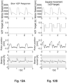
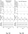
- Figure 12A An example of this is shown in Figure 12A , in which relatively high changes in bearing current are observed for given changes in impeller position.
- the impeller can move the reference power target in response to higher frequency disturbances such as suction and pulsing.
- This can provide significant benefits, for example when pulsing, as shown in Figure 12D , because changes in the bearing current are reduced and the system can stabilize high pulse magnitudes.
- This can reduce the effectiveness of using changes in bearing current to detect suction events, as described in copending application USSN 62/275723 , meaning suction events might instead need to be detected based on the impeller axial movement.
- the above described arrangement can be employed in wide range of circumstances and in different pump configurations. For example, this can be used when one or two pumps are used to provide assistance or replacement of the left or right ventricles, including in a TAH, when two rotary pumps to provide complete replacement of the native heart, in an LVAD/RVAD, when a single rotary pump is used to provide assistance to either the left or right ventricles, or in a BiVAD, when two rotary pumps to provide assistance to either the left or right ventricles.
- the heart pump 1300 includes a housing 1310 defining a cavity 1315.
- the housing can be of any suitable form but typically includes a main body, and left and right end caps which connect to the main body.
- the housing can be made of any suitable biocompatible material, and can be made of titanium, a polymer or the like.
- the housing 1310 includes an inlet 1311, for connection to the left atrium/pulmonary vein or right atrium/vena cava, or left or right ventricle, and an outlet 1313 for connection to the aorta or pulmonary artery, respectively.
- the heart pump 1300 includes an impeller 1320 provided within the cavity 1315.
- the impeller 1320 includes a rotor 1321 having vanes mounted thereon for urging fluid from the inlet 1311 to the outlet 1312 upon rotation of the impeller 1320.
- the impeller includes a single set of vanes 1322 for urging fluid from the inlet 1311 to the outlet 1312.
- the vanes 1322 have a configuration similar to that described above with respect to Figures 11I and 11J, and these will not therefore be described in further detail, although it will be appreciated that other suitable vane configurations can be used.
- the impeller can also include an aperture 1324 extending therethrough to allow blood to flow around the rear surface of the impeller and thereby prevent stagnation and clotting of blood within the heart pump. Furthermore, the use of a magnetic bearing in this region allows for blood gaps in excess of 200-300 ⁇ m, which can both reduces shear stress and thus red cell lysis, as well as promote greater rates of washout flow than otherwise anticipated in gaps created by hydrodynamic bearings.
- the heart pump 1300 further includes a drive 1330 that rotates the impeller 1320 within the cavity 1315.
- the drive 1330 can be of any appropriate form but typically includes a number of coils 1331, each wound on a respective stator 1332, supported by a mounting 1333, allowing the drive 1330 to be coupled to the housing 1310.
- the drive cooperates with magnetic material 1334 mounted in the rotor 1321, with the magnetic material being in the form of a number of circumferentially spaced permanent drive magnets arranged proximate an outer circumferential edge of the rotor 1321.
- the coils 1331 and stators 1332 are wedge shaped and circumferentially spaced around the mounting 1333, so as to provide twelve electromagnets radially aligned with the drive magnets 1334 in the rotor 1321, to thereby maximise a degree of magnetic coupling between the magnets in the rotor 1321 and the drive 1330.
- the heart pump 1300 can further include a magnetic bearing 1340 including at least one bearing coil 141 that controls an axial position of the impeller within the cavity 1315.
- the magnetic bearing includes three bearing coils 1341, each of which is mounted on a first leg 1342.1 of respective U-shaped stators 1342, with a second leg 1342.2 being positioned radially inwardly of the first leg 1342.1.
- the stators 1342 are mounted to or integrally formed with a support 1343 and circumferentially spaced 120° apart around the housing so that the first and second legs 1342.1 1342.2 align with respective magnetic material, such as bearing magnets 1344, 1345 within the impeller 1320, allowing an axial position of the impeller 1320 to be controlled.
- the bearing rotor assembly includes ferromagnetic core target 1344 mounted in the rotor, proximate an outer circumferential edge of the rotor 1321, and a permanent bearing magnet or ferromagnetic material 1345 mounted radially inwardly of the first ferromagnetic core target 1344, so that the ferromagnetic core target and bearing magnets 1344, 1345 align with respective legs 1342.1, 1342.2 of the stators 1342.
- the ferromagnetic core target can be replaced with a second permanent magnet.
- the use of a magnetic bearing may not be required and can be replaced by a static physical bearing or hydrodynamic bearing, or the like.
- the drive 1330 and magnetic bearing 1340 are mounted at opposing ends of the housing 1310 so that the drive and bearing 1330, 1340 are provided proximate opposing surfaces of the rotor 1321 as shown for example in Figure 13B .
- the drive 1330 is mounted adjacent the side of the impeller 1320 that includes vanes so as to maximise the blood gap between the rotor, vanes and the casing. That is to say, only the vane tips are in closer proximity to the casing, however this blood gap can still be in the order of 200-300 ⁇ m.
- bearing and drive are configured so that the magnetic forces inherent between the drive 1330 and impeller 1320, and between the magnetic bearing 1340 and impeller 1320 and the hydraulic forces on the impeller 1320 define a balance position within the cavity under conditions of normal flow. This minimises the bearing current required to maintain the position of the impeller 1320 within the cavity under nominal flow conditions.
- the apparatus can further include a controller, and otherwise functions largely as previously described, and hence will not be described in further detail.
- controller and control process can also be used in a device in conjunction with other control arrangements, such as those that use an active speed controller that controls the rotational speed of the impeller.
Landscapes
- Health & Medical Sciences (AREA)
- Engineering & Computer Science (AREA)
- Heart & Thoracic Surgery (AREA)
- Cardiology (AREA)
- Mechanical Engineering (AREA)
- Veterinary Medicine (AREA)
- Life Sciences & Earth Sciences (AREA)
- Public Health (AREA)
- General Health & Medical Sciences (AREA)
- Biomedical Technology (AREA)
- Animal Behavior & Ethology (AREA)
- Hematology (AREA)
- Anesthesiology (AREA)
- General Engineering & Computer Science (AREA)
- Physics & Mathematics (AREA)
- Geometry (AREA)
- Electromagnetism (AREA)
- Fluid Mechanics (AREA)
- External Artificial Organs (AREA)
- Structures Of Non-Positive Displacement Pumps (AREA)
- Vascular Medicine (AREA)
- Oral & Maxillofacial Surgery (AREA)
- Transplantation (AREA)
Description
- This application claims priority to and the benefit of:
U.S. Provisional Patent Application No. 62/275,754, entitled "Heart Pump," filed January 6, 2016 U.S. Provisional Patent Application No. 62/275,723, entitled "Heart Pump With Impeller Rotational Speed Control," filed January 6, 2016 U.S. Provisional Patent Application No. 62/275,744, entitled "Heart Pump With Impeller Axial Position Control," filed January 6, 2016 - The present invention relates to a heart pump and a controller for a heart pump controlling an axial position of an impeller in a heart pump.
- The reference in this specification to any prior publication (or information derived from it), or to any matter which is known, is not, and should not be taken as an acknowledgment or admission or any form of suggestion that the prior publication (or information derived from it) or known matter forms part of the common general knowledge in the field of endeavour to which this specification relates.
-
US-8,636,638 describes a controller for a heart pump that determines movement of an impeller within a cavity in a first axial direction, the cavity including at least one inlet and at least one outlet, and the impeller including vanes for urging fluid from the inlet to the outlet, causing a magnetic bearing to move the impeller in a second axial direction opposite the first axial direction, the magnetic bearing including at least one coil for controlling an axial position of the impeller within the cavity, determining an indicator indicative of the power used by the magnetic bearing and causing the magnetic bearing to control the axial position of the impeller in accordance with the indicator to thereby control a fluid flow between the inlet and the outlet. -
US-7,435,059 describes a system for pumping blood to assist or assume the cardiac function of a patient is characterized by a blood pump that exhibits a steep pump curve such that only small changes in pump flow occur for large changes in differential pressure across the pump. The pump therefore exhibits flow-limiting characteristics to protect the physiological system against harmful flow rates. Pump flow may also be limited by controlling the current provided to a driver from a power supply or by suitable restrictions within or external to the pump housing. - This arrangement provides a so called zero power configuration that attempts to minimise the power required by the magnetic bearing used to suspend the rotor. However, this does not provide adequate control of impeller position in all scenarios.
- The invention is set out in the appended set of claims.
- Various examples and embodiments of the present invention will now be described with reference to the accompanying drawings, in which: -
-
Figure 1A is a schematic perspective view of an example of a heart pump; -
Figure 1B is a schematic cutaway view of the heart pump ofFigure 1A ; -
Figure 1C is a schematic perspective exploded view of the heart pump ofFigure 1A ; -
Figure 1D is a schematic diagram of an example of a control system for the heart pump ofFigure 1A ; -
Figure 2 is a flowchart of an example of a control process for controlling an axial position of an impeller; -
Figure 3 is a flowchart of a specific example of a process for controlling an axial position of an impeller; -
Figures 4A to 4D are schematic diagrams illustrating an axial position of an impeller under varying conditions; -
Figure 5A is a graph illustrating magnetic force distribution on a magnetically levitated impeller; -
Figure 5B is a graph illustrating a relationship between bearing current and displacement under a variety of operating conditions; -
Figure 5C is a graph illustrating a relationship between axial stiffness and impeller axial position; -
Figure 6 is a schematic diagram illustrating a specific example of a controller architecture; -
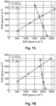
Figures 7A and 7B are graphs illustrating pulmonary vascular resistance and systemic vascular resistance for different axial position control algorithms; -
Figure 8 is a graph illustrating measurements of a mean magnetic bearing current versus axial impeller position; -
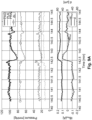
Figure 9A is a graph illustrating the impact of a "stand-up" event on various pump parameters; -
Figure 9B is a graph illustrating the impact of a "stand-up" event on various pump parameters for a traditional zero power controller; -
Figures 10A to 10C are graphs illustrating an example of rotational speed, bearing reference current and actual bearing current when reference power is not dependent on anticipated changes impeller speed; -
Figures 10D to 10F are graphs illustrating an example of rotational speed, bearing reference current and actual bearing current when reference power is set based on anticipated changes in impeller speed; and, -
Figures 11A to 11C are graphs illustrating examples of rotational speed, bearing reference current and actual bearing current measured during in-vitro experiments; -
Figures 11D to 11G are graphs illustrating examples of rotational speed, bearing reference current, impeller position and actual bearing current measured during in-vitro experiments; -
Figures 12A to 12D are graphs illustrating examples of the responsiveness of different impeller positional control strategies; -
Figure 13A is a schematic perspective view of an example of a single VAD heart pump; -
Figure 13B is a schematic cutaway side view of the heart pump ofFigure 13A ; -
Figure 13C is a schematic cutaway plan view of the heart pump ofFigure 13A ; -
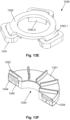
Figure 13D is a schematic perspective view of the impeller of the heart pump ofFigure 13A ; -
Figure 13E is a schematic perspective view of the magnetic bearing of the heart pump ofFigure 13A ; and, -
Figure 13F is a schematic cutaway perspective view of the impeller ofFigure 13A . - An example of a heart pump will now be described with reference to
Figures 1A to 1D . - In this example the heart pump is a biventricular device, which can operate either as a ventricular assist device to assist function of left and right ventricles of a subject's heart, or alternatively as a total artificial heart. It will be appreciated however that whilst reference is made to a biventricular device this is not essential, and alternatively the control processes described herein could equally be applied to single ventricular assist devices or any other form of blood pump.
- In this example, the
heart pump 100 includes ahousing 110 defining acavity 115. The housing can be of any suitable form but typically includes a main body 110.1, left and right end caps 110.2, 110.3 which connect to the main body 110.1, as well as an end plate 110.4 positioned between the main body 110.1 and left end cap 110.2. The housing can be made of any suitable biocompatible material, and can be made of titanium, a polymer or the like. - The
housing 110 includes twoinlets outlets - The
heart pump 100 includes animpeller 120 provided within thecavity 115. Theimpeller 120 includes arotor 121 having vanes mounted thereon for urging fluid from the inlet to the outlet upon rotation of theimpeller 120. In this example, as theheart pump 100 is a biventricular device, the impeller includes two sets ofvanes respective inlet respective outlet rotor 121 is positioned within thecavity 115 to effectively divide the cavity into first and second cavity portions, each having a respective inlet and outlet, thereby allowing each to function as a respective pump. - Thus, in the current example, the
vanes 122 are used to urge fluid from theinlet 111 to theoutlet 112, with this being provided on the left-hand side of the pump in the orientation shown inFigure 1B , and operating to provide left-ventricular function, whilst thevanes 123 urge fluid from theinlet 113 to theoutlet 114 and act to provide right-ventricular function. In this context the first and second cavity portions are generally referred to as left and right cavities, respectively. It will be appreciated that in this regard, the terms left and right refer to the intended ventricular function of the cavities as opposed to the particular orientation of the pump inFigures 1B , which is used for illustrative purposes only. - The
heart pump 100 further includes adrive 130 that rotates theimpeller 120 within thecavity 115. Thedrive 130 can be of any appropriate form but typically includes a number ofcoils 131 wound on astator 132, supported by amounting 133, allowing thedrive 130 to be coupled to thehousing 110. The drive cooperates withmagnetic material 134 mounted in therotor 121 with this typically being in the form of a number of circumferentially spaced permanent magnets mounted in therotor 121 proximate an outer circumferential edge of the rotor and proximate a face of the rotor facing thedrive coils 131. In one specific example, thecoils 131 andstators 132 are wedge shaped and circumferentially spaced around themounting 133, so as to provide twelve electromagnets radially aligned with circumferentially spaceddrive magnets 134 in therotor 121, to thereby maximise a degree of magnetic coupling between the magnets in therotor 121 and thedrive 130. Thedrive magnets 134 are typically arcuate shaped rare earth magnets, circumferentially spaced proximate an outer circumferential edge of therotor 121, and mounted on a soft iron rotor drive yoke. - The
heart pump 100 can further include amagnetic bearing 140 including at least onebearing coil 141 which cooperates with bearing magnetic material mounted in therotor 121 to thereby control an axial position of theimpeller 120 within thecavity 115. In one particular example, shown in more detail in Figures 2D to 2F, the magnetic bearing includes three bearingcoils 141, each of which is mounted on a first leg 142.1 of respectiveU-shaped stators 142, with a second leg 142.2 being positioned radially inwardly of the first leg 142.1. Thestators 142 are mounted to asupport 143 and circumferentially spaced 120° apart around the housing so that the first and second legs 1421. 142.2 align with respective bearing magnetic material, such as bearingmagnets impeller 120 to be controlled. - The bearing magnetic material typically includes first and second annular magnetic bearing members mounted within and proximate a face of the rotor facing the bearing coils 141, the first magnetic bearing member being provided radially outwardly of the second magnetic bearing member. In one particular example, the first
bearing magnet material 144 includes an annular soft iron material that can be integrally formed with the annular yoke, or an annularpermanent magnet 144 mounted on the yoke, and mounted in the rotor, proximate an outer circumferential edge of therotor 121. The second bearing magnetic material is an annularpermanent bearing magnet 145 mounted radially inwardly of thefirst bearing member 144, so that the first andsecond bearing members stators 142. It will be appreciated the annular members could include a plurality of individual elements, such as individual circumferentially spaced magnets or ferromagnetic elements. Additionally, the use of a magnetic bearing may not be required and can be replaced by a static physical bearing, or the like. - The
drive 130 andmagnetic bearing 140 are mounted at opposing ends of thehousing 110 so that the drive and bearing 130, 140 are provided proximate opposing surfaces of therotor 121 as shown for example inFigure 1D , and Figures 2G, 2H, 2J and 2K. In the current example thedrive 130 is mounted adjacent the left pump, whilst thebearing 140 is mounted adjacent the right pump, although the opposite configuration is contemplated. The depicted arrangement has a number of benefits. - Firstly, the inherent attractive magnetic forces between the drive and rotor and the bearing and rotor can be configured to substantially balance when the rotor is provided at a balance point at a normal operating speed, which may for example by approximately at a center of the cavity under conditions of normal flow.
- For example, this arrangement can be configured so that the magnetic forces inherent between the
drive 130 andimpeller 120, and between themagnetic bearing 140 andimpeller 120 are matched at an impeller balance position within the cavity, which corresponds to a desired position of the impeller under conditions of normal flow. This minimises the bearing current required to maintain the position of theimpeller 120 within the cavity, hence reducing the amount power required to operate, and in particular drive and axially position the impeller. - Additionally, as well as having the magnetic forces balance, the forces generated by the drive and bearing can also be configured to provide a desired degree of axial and radial stiffness. In this regard, the stiffness is a measure of the deflection of the
impeller 120 from a balance position in response to an external force. In one example, it is desirable to maximise the radial stiffness so as to maintain the impeller radially centralised within the cavity and to stop the impeller touching the inner circumferential wall of the cavity. Conversely, as the axial position of theimpeller 120 can be used for flow control, and in particular to allow for passive and/or active response to changes in hemodynamic parameters, a low degree of axial stiffness is preferred. Accordingly, the passive magnetic forces can be configured to assist in meeting these requirements, as will be described in more detail below. - A further benefit of the above described arrangement, in the context of BiVAD applications, is that it allows the greater size of the magnetic bearing to be accommodated by the smaller size of the right pump cavity. In particular, this allows a gap between a bearing stator and bearing magnets to be minimized, as no vanes are located in this gap (as opposed to the left side where vanes are located in the magnetic airgap between the drive and the rotor), as will be described in more detail below. However, it will be appreciated that this limits an outer diameter of the right pump and thus achievable pressure generation at a given rotational speed, although for right pumps this is generally not an issue given their lower flow requirements than the left pump.
- The apparatus further includes a
controller 150 which, in use, is coupled to asensor 160 and the drive and bearingcoils sensor 160 senses an axial position of theimpeller 120 within thecavity 115 and can be of appropriate form such as a reluctance or eddy current sensor, which detect magnetic fields within therotor 121 to thereby determine a separation between the rotor and thesensor 160, as will be appreciated by persons skilled in the art. - Typically three sensors would be provided circumferentially spaced around the rotor. In the case of eddy
current sensors 160, each sensor would typically include a coil mounted in a housing, circumferentially spaced and aligned with the inner leg 142.2 of themagnetic bearing stators 142. The coil is aligned with a rotor shell/target mounted radially inwardly of afirst bearing magnet 144, so as to generate a field therein, with variations in the field being detected to determine the separation of thesensor 160 and the shell/target, and hence therotor 121. However, it will be appreciated that other suitable sensors can be used, such as reluctance sensors or the like, in which case the firstpermanent magnet 144 might be replaced with ferromagnetic material, depending on the sensor/bearing requirements. - In use the
controller 150 is adapted to monitor signals from theposition sensor 160 and then control the current supplied to the drive coils 131 to control rotation of the impeller and to the bearing coils 141 to control the axial position of theimpeller 120. - The
controller 150 can be of any suitable form but typically includes anelectronic processing device 151, anoptional memory 152, and aninterface 154 for connecting to the heart pump, each of which are interconnected by abus 155, or other similar arrangement. The electronic processing device can be any form of electronic processing device capable of interpreting signals and causing the drive and bearing to be controlled, such as a microprocessor, microchip processor, logic gate configuration, firmware optionally associated with implementing logic such as an FPGA (Field Programmable Gate Array), or any other electronic device, system or arrangement. - An optional
external interface 153 may be provided allowing for interaction with thecontroller 150. In the event that the controller is positioned outside the body this could include an I/O device 153 such as a touch screen or the like, whereas if positioned inside the body this would typically be in the form of a wireless communications module allowing communication with an external control device. - Operation of the
control system 150 ofFigure 1D will now be described with reference toFigure 2 . - In this example, when operating under normal conditions, the
impeller 120 is magnetically suspended within thecavity 115, with hydraulic forces acting on theimpeller 120 due to fluid pressure within each of the left and right cavities and magnetic forces generated by thedrive 130 and bearing 140 being substantially balanced. In this instance theimpeller 120 is typically suspended at a reference position within the cavity, sometimes referred to as a central position. - At
step 200, a pressure change occurs within one or both of the left or right cavities. The pressure change would typically occur as a result of a physiological change within the subject which could arise for any one of a number of reasons, such as the subject moving, commencing exercise, or the like. The pressure change will generally result in a change in the hydraulic forces acting on theimpeller 120 resulting in a net force towards the left or right cavity for the current bearing settings. - At
step 210, thecontroller 150 determines the axial position of theimpeller 120, and uses this to determine a reference power atstep 220. In particular, the reference power is defined as a function of impeller position, with the reference power varying based on a distance of the impeller from the notional central position with the cavity. - At
step 230, thecontroller 150 moves the impeller by controlling themagnetic bearing 140 to cause theimpeller 120 to move until a bearing power indicator indicative of the power used by the magnetic bearing reaches the reference power. - The bearing power indicator can be of any appropriate form, but in one example is indicative of or derived from the bearing current drawn by the magnetic bearing, for example based on a filtered version of the raw current signals, with the reference power corresponding to a respective current value. However, it will be appreciated that this is not essential, and any suitable bearing power indicator and corresponding type of reference values can be used.
- In the above process, when moving the impeller this typically involves moving the impeller in a direction opposite the direction of the net force on the
impeller 120, so that for example if the net force is acting towards the right cavity, for example due to an increase in pressure in the left cavity, themagnetic bearing 140 is controlled to cause theimpeller 120 towards the left cavity. This movement brings theimpeller 120 towards thedrive 130, thereby increasing attractive forces between thedrive 130 andimpeller 120, while reducing attractive forces between the bearing 140 andimpeller 120, which in turn helps counteract the hydraulic forces, reducing the bearing current required to maintain the impeller at a balance position. - It will be appreciated that this is broadly similar to the "zero-power" controller configuration described for example in
US-8,636,638 . However, in contrast to the technique described therein, in which a constant and typically minimal reference power is used, the reference power is defined as a function of the axial position of the impeller within the cavity. Accordingly, as the impeller moves within the cavity, thecontroller 150 repeatssteps 210 to 230, determining a new reference power based on the new axial position of theimpeller 120, using this to control further movement of theimpeller 120. - In one example, the reference power determined by the controller increases as the
impeller 120 moves away from the notational centre point within the cavity. The effect of this is that when compared to a traditional zero-power control process, additional movement of the impeller is induced. Thus, in this example, when moving the impeller towards the left cavity, the further movement will typically include moving the impeller further towards the left cavity, in effect amplifying the movement induced by the zero-power control approach. - The reason for performing additional movement control is to amplify changes in fluid flow between the inlet(s) and outlet(s). In this regard, movement of the impeller has an impact on the efficiency of the pump, with a reduction in separation between the
vanes impeller 120 within thecavity 115 can be used to increase or decrease pump flow. - In the case of a single ventricular device moving the impeller can be used to increase or decrease flow. In a biventricular device however, this can increase/decrease one pump output, whilst simultaneously decreasing/increasing the other pump output, which is particularly useful in balancing fluid pressures between the left and right cavities, and hence within the systemic and pulmonary circulatory systems in the subject. For example, a decrease in left-ventricular pressure requires an increase in blood flow through the left ventricle in order to return pressure to normal levels. Accordingly, this can be achieved by moving the impeller towards the left cavity, increasing the effectiveness of left ventricular function.
- It will be appreciated from the above that a greater movement of the impeller will result in a higher increase in efficiency of the pump and hence a higher fluid flow, which in turn returns pressures to a balanced condition more effectively. As a result, there is a desire to effectively maximise the degree of movement for any particular change in pressures and hence hydraulic forces within the pump.
- In this regard, the degree of axial movement of the
impeller 120 within thecavity 115 will naturally vary depending on the axial stiffness of the magnetic bearing arrangement. In particular, a relatively weak stiffness will result in a higher degree of axial movement for a given pressure change, which in turn can enhance the effectiveness of the ability of the heart pump to correct pressure imbalances, for example between the left and right sides. Conversely, a magnetic bearing with a high degree of stiffness will result in a relatively small amount of axial movement for a given pressure change, meaning the effectiveness to correct pressure imbalances in reduced. - From this, it will be appreciated that one option to maximise movement of the impeller, and hence the effectiveness of the pump to correct imbalances is to use an axially weak magnetic bearing. However, the axial stiffness of the magnetic bearing is dependent on the degree of magnetic coupling between the bearing 140 and
impeller 120, which in turn also affects the radial stiffness, meaning an axially weak magnetic bearing is also radially weak, which in turn allows for radial movement of the impeller within the cavity. Such radial movement is undesirable as this can lead to contact between therotor 121 and an inner wall of thecavity 115, which can cause damage to the pump. Additionally, even if contact does not occur, a small separation between therotor 121 and cavity wall can lead to high shear stresses, which in turn can case rupturing of blood platelets leading to hemolysis. - Accordingly, in one example it is desirable to provide a magnetic bearing that has significant radial stiffness, so as to restrict radial movement of the impeller, but which at least mimics the effect of an axially weak bearing. This can be achieved through the utilisation of the above described control process which uses a physically strong axial magnetic bearing, and hence a radially strong bearing, but implements additional control processes in order to simulate the effect of an axially weak bearing. This assists in providing a magnetic bearing that allows the pump to respond to pressure changes within the cavities to balance flows, whilst preventing radial movement of the impeller. However, it will be appreciated that the techniques described herein can be conversely used to increase the effective axial stiffness, which can be used to avoid the impeller reaching an extreme axial position within the cavity, as will be described in more detail below.
- A number of further features will now be described.
- As previously mentioned, the control process operates to move the impeller in a direction opposite a net force induced on the impeller. Accordingly, when the change in hydraulic forces generates a resultant force acting on the impeller in a first axial direction, the controller controls the magnetic bearing to move the impeller in the second axial direction opposite to the first axial direction. Thus, an increase in pressure in the left cavity will cause the impeller to be moved towards the left cavity.
- The
controller 150 can determine changes in axial hydraulic forces within the cavity either by detecting axial movement of the impeller within the cavity, for example by detecting movement in the first direction, or by detecting changes in the bearing power indicator required to maintain the impeller at a constant axial position within the cavity. The technique used will vary depending upon the preferred control implementation. In particular, in one example, thecontroller 150 can implement a bearing control process which operates to adjust the power used by themagnetic bearing 140 in order to maintain theimpeller 120 at a constant position, in which case changes in bearing power will be used to determine the net forces, whereas alternatively thecontroller 140 could attempt to maintain a constant power, in which case movement of theimpeller 120 would be detected. - In one example, the controller determines changes in axial hydraulic forces by filtering a bearing current signal using a low pass filter. The low pass filter can have a cut-off of at least one of: between 0.1-10Hz, between 1-15Hz; between 15-30Hz; approximately 15Hz; approximately 30Hz; approximately 1Hz; and, between 30-100Hz.
- Typically the
controller 150 operates to iteratively move theimpeller 120 by repeatedly controlling the magnetic bearing to move theimpeller 120 to a new axial position in accordance with the reference power, then modifying the reference power in accordance with the new axial position of the impeller. This process can be repeated until a desired end point is reached. This can be performed on the basis of a set number of iterations but more typically is performed until the modified reference power reaches a defined threshold value, the axial position reaches a defined threshold or the hydraulic forces are either balanced or overcome. Thus, it will be appreciated that this process can continue until theimpeller 120 reaches a maximum extreme position within thecavity 115, for example corresponding to a distance of minimum separation from the cavity wall, or until the hydraulic forces are again balanced. - In one particular example, the operating range of the impeller is restricted to +/-200µm when operating in a total 0.6mm clearance, so as to not allow the impeller to come with 100µm of the stationary housing to assist with hemocompatibility. However the rotor may be able to come within 50µm of the stationary casing at critical times to assist with flow balancing, effectively expanding the range of movement to +/-250 µm. It would be appreciated that these limits from the housing are fixed, resulting in a larger operating range as total clearance gap increases.
- In one example, it can be desirable to operate the bearing so that the impeller does not reach an axial position limit, for example to accommodate changes in impeller rotational speed, which can in turn impact on the magnetic forces generated by the drive. For example, if the impeller reaches an axial position limit, the impeller can't move any further so additional changes in forces acting on the impeller must be counteracted solely by changes in the magnetic forces generated by the bearing and hence the bearing current used, and not the usual control of changes in bearing current and impeller position. This can lead to excessive changes in bearing current, which can in turn impact on other control processes, such as the detection of characteristic force events or control of impeller rotational speed, described for example in copending application
USSN 62/275723 - Accordingly, in one example, the above described control process can be used to alter the effective stiffness of the system different for different regions of the operational range. For example, as the impeller gets closer to a positional limit, the controller can be used to increase the effective axial stiffness of the bearing, which would mean that a further increase of the forces would result in a smaller axial movement.
- In one example, the system can have a dynamic effective axial stiffness based on the impeller position, so that in a central region of the cavity, the impeller can have a low axial stiffness to provide maximum axial and hence hemodynamic responsiveness. Conversely, towards limits of axial position, the stiffness can be increased to thereby reduce the axial responsiveness, thereby avoiding the impeller passing beyond limits and impacting on the housing, whilst also reducing the likelihood of current peaks or spikes impacting on other control algorithms or resulting in excess power use.
- It will also be appreciated that the impeller position can be controlled on the basis of a first limit and a second limit, with the first limit defining a preferred impeller position range and the second limit defining a maximum impeller position range. In this regard, the first limit can provide a soft limit, which is a notionally preferred limit to the axial position, as compared to a hard limit defined by the second limit, which is an axial position beyond which there is a risk of the impeller contacting the housing.
- The
controller 150 typically determines the reference power by progressively increasing a magnitude of the reference power by a progressively smaller amount for each iteration, such that the degree of movement reduces on each iteration as theimpeller 120 moves away from the zero-power reference position. This allows the impeller to be moved asymptotically towards a new balance position, in particular allowing for initial rapid coarse correction, with fine correction being implemented as the impeller reaches a new balance position. However, any function relating the reference power to the axial position of the impeller within the housing can be used, for example to reduce the amount of movement when compared to the traditional zero power configuration, thereby providing a bearing that is effectively axially stiffer. - In one example, the
controller 150 controls the magnetic bearing to cause theimpeller 120 to move to a target axial position. Thecontroller 150 then determines if the bearing power indicator is at the reference power at the target positon, and if not, determines a new target axial position of the impeller, determines a reference power in accordance with the new axial position and uses the reference power to determine a new target axial position. This process can then be repeated providing a positive feedback loop, until such time as the bearing power indicator reaches the reference power, when at the current defined target position. - In one example, the
controller 150 includes a bearing controller that uses signals from theposition sensor 160 to determine the current axial position of theimpeller 120, controls the current supplied to the magnetic bearing to thereby maintain theimpeller 120 at a target axial position and outputs an indication of the bearing power indicator and current axial position. Thecontroller 150 then further includes a position controller that uses the bearing power indicator and current axial position to determine a target axial position which is then provided to the bearing controller. In this regard, the bearing and position controllers could include physically separate hardware, but more typically are logically separate control processes implemented on a common processing device, as will be described in more detail below. - Furthermore, the position controller can include a first controller that calculates a reference power using the current axial position of the impeller and a second controller that determines the target axial position using the reference power and the bearing power indicator. Additional details of the control arrangement will be described in more detail below.
- The
controller 150 can also operate to record an indication of the bearing power indicator and such or the current axial position allowing this to be reviewed, for example for logging purposes. - Accordingly, the above described processes allow a heart pump to be implemented with a magnetic bearing system having a high degree of axial stiffness, whilst maintaining a degree of control over flow balance typically only achievable with a low stiffness bearing configuration.
- A further example control process will now be described with reference to
Figure 3 andFigures 4A to 4D . For the purpose of this example, bearing current is used as an indicator of bearing power, but it will be appreciated that this is not intended to be limiting in the context of the application as a whole. - In this example, at
step 300, thecontroller 150 monitors aposition sensor 160 and determines if theimpeller 120 is at a target position atstep 310. Under nominal flow conditions (referred to as balanced conditions), theimpeller 120 is provided at an initial reference position RP, with the bearing current IB remaining substantially constant at a reference level IBref, as shown inFigure 4A . If there is no impeller movement, and the impeller is at the target position, the process returns to step 300, allowing the position to be monitored in an ongoing process. - Assuming there is impeller movement, the
controller 150 will adjust the bearing power to maintain theimpeller 120 at the target impeller position, initially corresponding to the reference position RP. In the example ofFigure 4B , an increase in left ventricular pressure leads to a net hydraulic force towards the right cavity, as shown by the arrow FH, which initially causes movement of the impeller to the right cavity. Accordingly, thecontroller 150 adjusts the current used by the magnetic bearing, reducing the attractive force between theimpeller 120 andbearing 140, so as to counteract the hydraulic force FH. In this regard, it will be appreciated, that this may involve reducing the magnitude of the applied bearing current, or applying a negative bearing current to repel theimpeller 120 from the bearing, depending on the magnitude of the reference current IBref. It should be noted that the term reference current IBref is effectively equivalent to the reference power, and these two terms should be considered as interchangable. -
Steps 300 to 320 are typically performed by on a continuous basis so as to maintain the impeller at a defined target position within the cavity. - At
step 330, thecontroller 150 determines the bearing power indicator in the form of the bearing current IB and determines if this is equal to the reference power IBref atstep 340. If not, atstep 350, thecontroller 150 determines the position of theimpeller 120, with this being used to determine a reference power atstep 360, which is in turn used to determine a new target position. - In this instance, initially the impeller is provided at the initial reference position RP, which is generally at a notional centre of the cavity, and accordingly the reference power is IBref, which results in the impeller moving towards a target position located in the left cavity. This is achieved by initially reducing the magnitude of the applied bearing current IB, or applying a negative bearing current to repel the
impeller 120 from thebearing 140, until the impeller reaches the target position, as shown inFigure 4C . In the previous zero-power approaches, the impeller would halt at the position once the bearing power reaches the reference power IBref - However, in the current example, as the impeller moves towards the target position shown in
Figure 4C , thecontroller 150 repeats the process ofsteps 340 to 370, progressively adjusting the reference power as theimpeller 120 moves. In this example, the target position of the impeller is progressively adjusted until the impeller reaches a target position in which the bearing power indicator is equal to a boosted reference power IBBoost, shown inFigure 4D . Thus it will be appreciated that the modified zero-power control approach causes theimpeller 120 to be moved further into the left cavity. - Accordingly, in the above described arrangement, the magnetic bearing system has a dual purpose: namely levitating the rotor and maintaining axial and radial stability, as well as enabling axial rotor translation to provide flow control, and in particular differential flow control in the case of a biventricular assist device. To maintain stability, the bearing system is preferably "stiff', so that a small radial or axial movement results from disturbing physical forces created by the motor's magnetic field, or the patient's movement act on the rotor. In contrast, for flow control the axial bearing needs to be "soft", so that a change in left or right atrial pressure shall result in a large axial rotor movement to balance left and right outflows.
- The system's stiffness is determined by the mechanical and electrical design of the device, and in particular the drive and bearing design, so this needs to be determined during the design phase. However, implementing an axially stiff bearing may not fully utilize the available impeller movement range within the cavity of the device, when encountering disturbance forces created by variations in inflow and outflow pressures. Therefore, it may be desired to attain an "overreaction", in which greater impeller movement is performed. By implementing the above described control processes, this allows a physically stiff bearing to function in a manner similar to that of an axially soft bearing, allowing the benefits of both stiff and soft bearings to be achieved.
- As previously described, in the current arrangement, the impeller is axially suspended by two magnetic fields, created by the
drive 130 on the left and the bearing 140 on the right. Each field creates a force FM and FB that acts on the impeller, with examples of the forces being shown inFigure 5A . - In this example, the displacement d is counted positive towards the right cavity, with the point P1 corresponding to a balanced position in which the drive and magnetic bearing forces are equalized. The steeper the force curves, the higher the absolute system stiffness |F/d| and the better axial and radial stability. The impeller is maintained in position by an active controller system, so to reduce the energy consumption, a portion of the bearing force FB is created by permanent magnets so that less or no current in the bearing coils is required to maintain the position.
- In order to adjust the impeller position, the coils are energized with a bias current IBRef A typical bearing current IB versus displacement curve IBFB is plotted in
Figure 5B . Adding a positive current moves the rotor towards the left cavity, whilst a negative current would move the rotor towards the right cavity. - When the bearing system is operated in zero-power mode, the controller seeks to minimize IB to zero, so that FB is solely created by the permanent magnets. With the zero-power mode activated, a hydraulic force FH on the rotor in axial direction will move it opposite to the force's direction. Thus, in
Figure 5A , FH acts towards the right, which increases the total force FB+FH towards the right cavity. If the impeller position were maintained, a bearing current IB would be required in order to reduce the bearing force FB. However, the zero-power controller aims to minimize IB, which is achieved by moving the impeller towards the left cavity, to the new point of equalized forces, point P2, where IB is minimal. - In
Figure 5B , the result of the additional force can be observed as a shift of bearing current IBFB towards the left, as shown by curve IBFB+FH. The impeller moves by the distance Δd2. In order to allow for a rotor position adjustment, while under zero-power control, a non-zero value for IBRef can be selected. For the purpose of responding to changes in the hydraulic forces with an appropriate rotor movement, the stiffness FHlΔd2 is required to be low. - Thus, the fundamental control strategy of a zero-power controller is to minimize power consumption of the magnetic bearing system by reducing the average bearing current to zero.
- The arrangement described above builds on the pre-existing zero-power system, manipulating IBRef by adding a booster current IBBoost, the additional current IBBoost is selected depending on the current impeller position, as shown by the dashed line in
Figure 5B , resulting in the impeller moving by the distance Δd3 to the position P3. By this means a feedback loop is created that allows to amplify the impeller movement for given hydraulic forces, thereby simulating a lower stiffness. - As also previously mentioned, it can be desirable to have a dynamic stiffness that adjusts based on the impeller position. An example of this is shown in
Figure 5C . In this example, the effective axial stiffness is shown in N/mm, so towards the centre of the cavity the impeller has a low effective axial stiffness, so a 1N net force on the impeller would move the impeller a large axial distance, whereas towards the soft limits the effective axial stiffness increases so that 1N net force moves the impeller a smaller axial distance. - As previously mentioned, the ability to adjust the effective axial stiffness can be beneficial for a number of reasons. For example, while a softer bearing can benefit in scenarios where additional rotor movement is advantageous, such as enhancing hydraulic balancing with axial rotor movement, increased stiffness system can be used to reduce the movement of the impeller when it is located in juxtaposition to certain positions within the housing. This can be applied to prevent the rotor from operating close to the physical housing or to some defined point within the housing, such as within 100µm from the physical housing limit.
- Where a change, and in particular an increase in effective axial stiffness is desired, the reference power can be manipulated such that further movement towards the housing or defined point is countered with a change to IBRef to reduce the resulting movement, resulting in an effectively stiffer bearing. This localised change in the reference power allows for the device to operate with a normal or simulated soft bearing stiffness in some regions, while operating with a simulated stiffer bearing in others.
- This effectively stiffer bearing can be practically realised by modifying the booster current IBBoost such that it has an opposite gradient with respect to impeller position when compared to the simulated soft bearing example. Thus, the booster current IBBoost can be linear, or non-linear, so choosing an appropriate quadratic or exponential relationship would allow for the simulated stiffness of the system to increase rapidly when the rotor is located close to a defined point, as shown in
Figure 5C . - An example controller configuration is shown in
Figure 6 . - In this example, the
controller 150 includes a bearingcontroller 601 that outputs a position indication d and bearing current IB, both of which are filtered by respective low pass filters 602, 603. The filtered position is provided to abooster controller 604, which generates a booster current based on the position of theimpeller 120. This is combined with a default current IB0, to create a reference current IBref The filtered bearing current is subtracted from the reference current IBref and passed to theposition controller 605, which generates a target position dref, which is returned to the bearingcontroller 601, allowing the bearing controller to control the bearing based on the current position of theimpeller 120. - The movement "overreaction" was achieved by selecting a function, which increases bearing current IB with decreasing d, as shown by IBBoost in
Figure 5B . In a case, where the zero-power controller moves the impeller towards the left cavity, the booster adds the current IBRef, which moves the rotor even further to the left. A positive feedback loop is created. Stability is maintained as long as at the same distance d the gradient of IBBoost (GB) is bigger than the gradient of the native current-displacement function IBFB (GN). As long as this stability criteria is maintained, the booster function can have an arbitrary shape. In the current implementation it is linear to either side of P1, however different gradients, including linear and non-linear can be selected. - To limit the power consumption, the amount of the booster current was limited to ±0.5A. A manual adjustment of the rotor position is still possible by altering IB0 or by modifying the attractive force of the motor through changes to the electromagnetic field.
- By knowing the gradient of the native current-displacement function GN, the amount of gained movement can be approximated. Without loss of generality it can be assumed that P1 is located in the origin. Consequently, for P2 (zero-power) and P3 (zero-power & Booster) the following equations can be formed:


- By transforming equation (2) to IBRef and substituting into equation (1), the booster factor can be given with:

- The performance of the above described approach was evaluated in-vitro by assessing the balancing ability by means of resistance boxes, shown in
Figures 7A and 7B for standard zero-power control and the modified zero-power control (zero-power booster) described herein. Based on preliminary results the booster gains of GB=-2 and -0.8 A/mm, for a movement towards left and right respectively, were selected. These values allowed to utilize the maximal movement range, while system stability is ensured. Results are shown in table 1 below:Table 1 Configuration AMod [%] AExt [%] d [µm] zero-power 87.0 30.9 -58 to 200 (Δd = 258) zero-power Booster 95.6 38.0 -186 to 230 (Δd = 416) - Additionally, a feasibility study was conducted in-vivo using a heart pump implanted in a calf. Pressures were measured with pressure catheters, with flows being measured using perivascular transonic flow probes.
- The in-vivo data were extracted from the post-operative days (POD) 1 and 2, in these two days the zero-power booster was active for 14.75 hours. In
Figure 8 the mean magnetic bearing current is plotted against the axial motor positon from a 45min phase, when the gain was -1A/mm and speed and bias current IB0 were maintained constant. By varying the bias current IB0, GN was measured with -2A/mm for this displacement range. - The additional mean power consumption of all three bearing coils, caused by the zero-power Booster, was calculated with equation 4. With Ibx as the instantaneous current in bearing X; Ib0 the manual bias current; and RB the bearing resistance including drive line with a value of 2.5Ω. The bearing power consumption, averaged over the whole in-vivo time with activated zero-power Booster, was 0.13W, with peaks up to 2W in phases of high PVR.

- The haemodynamics, the reference current IBRef and the axial rotor position (d) during a stand up event with active zero-power Booster is shown in
Figure 9A . Shortly after the stand-up event, both PAO (aortic pressure) and PLA (left atrial pressure) are decreased, while PRA (right atrial pressure) is increased. In order to redistribute the pooled right atrial blood volume, the impeller moves towards the right side. Within less than one minute the aortic pressure recovers. In this case the rotor translated by ~80µm towards the right side. Based onequation 3, with GB = -1A/mm and an approximated GN = -2A/mm, this was a 100% improvement. - In
Figure 9B a stand up event without booster algorithm is plotted. Since only the VZP controller was active, the reference current IBRef was maintained constant at 0A. Consequently, when the results fromFigure 9A and9B are compared, then the rotor's travelled distance increased from 40µm to 80µm and the achieved drop in the left pump pressure difference (deltaL) increased from 12mmHg to 14mmHg, for without and with the booster algorithm respectively. The larger drop in deltaL aims to reduce the drop in PLA, which can ultimately reduce the risk for left atrial suction. - Accordingly, the above described control approach allows a stiff and robust magnetic bearing system to be implemented, while allowing the impeller axial positional response to changes in hydraulic forces to be controlled independently. Consequently, an amplified or dampened response, can be realized. In contrast to the zero-power controller response this behaviour can be reprogrammed after the device design and during device operation and can be varied based on rotor position within the casing. The results demonstrated that the rotor's axial movement range improved and thereby the physiological response. The required additional energy was marginal and yet can result in significant patient benefit, in particular allowing the impeller position to be adjusted rapidly to the physiological requirements of the patient.
- Whilst the above have focussed in simulating a softer bearing, with enhanced axial movement for a change in force, it will be appreciated that this is not essential, and any form of control strategy can be used by changing the function used to determine the modified reference power, and hence the ultimate position to which the impeller moves.
- In the above described arrangement, the
controller 150 implements a bearing control strategy that controls a position of theimpeller 120 in accordance with a reference power, with the reference power being set in accordance with an axial position of the impeller within a cavity. However, this is not essential, and the reference power could alternatively or additionally be set based on other operating characteristics of the heart pump. - In this regard, the bearing control approach typically takes a finite amount of time to respond to changes in the hydraulic forces/motor attractive forces acting on the impeller. In the event that it is known that the hydraulic forces are to change, this can be accommodated by adjusting the reference power, so that the bearing axial position is adjusted in advance of, or during, the change. Whilst such changes in hydraulic force can arise for any one of a number of reasons, such as changes in a physiological state of the subject, these are typically difficult to anticipate, so more typically this is as a result of changes in pump operating parameters that can be anticipated in advance of these occurring, for example by virtue of these being controlled by the controller.
- In one particular example, the changes in parameters include a change in the rotational speed of the impeller. In this regard, a change in rotational speed of the impeller results in changes in flow and hence pressure within the left and right pumps, which in turn changes a pressure differential across the impeller, in turn resulting in a net hydraulic force. It will also be appreciated that speed changes will also result in a change in the hydraulic forces on a single sided impeller used in a VAD application, and accordingly, this is not intended to be limited to Biventricular (BiVAD/TAH) configurations. Additionally, changes in rotational speed necessitate changes in the magnetic field generated by the drive, which in turn result in a change in attractive forces between the
drive 130 andimpeller 120. It will be appreciated that such changes arise for general changes in rotational speed, as well as pulsing in rotational speed, as may be required for example to mimic a human pulse. - In one particular example, the changes in parameters include a change in the rotational speed of the impeller. In this regard, due to the increased strength of the magnetic field required to increase the motor speed or maintain a higher load the axial attractive force between the motor and the rotor would increase. The magnitude of this increase a function of the motor design, the motor control algorithm and the rate of speed change.
- In any event, in one example, the controller determines pump operating parameter changes that will cause a change in hydraulic forces on the impeller, determines a reference power in accordance with the pump operating parameter changes and controls the magnetic bearing to cause the impeller to move until a bearing power indicator indicative of the power used by the magnetic bearing reaches the reference power.
- In one particular example, the controller determines a change in rotational speed of the impeller and determines the reference power (current or voltage) and/or position in accordance with the change in rotational speed of the impeller, with the controller controlling the magnetic bearing in accordance with the reference power either prior to or during the change in rotational speed of the impeller. This allows the changes to hydraulic forces/motor attractive forces arising due to the change in rotational speed of the impeller to be accommodated by the magnetic bearing more rapidly than would otherwise be the case.
-
Figures 10A to 10C and 10D to 10F illustrate an example of the effect of changes in rotational speed of an impeller on the resulting magnetic bearing current used for a situation in which a target reference current remains unchanged (Figures 10A to 10C ) and in which the target reference current is varied pre-emptively in anticipation of a periodic rotational speed change (Figures 10D to 10F ). In this regard, a periodic variation of impeller rotational speed shown generally at 1000, causes a change of both hydraulic forces and motor attractive forces. When the reference current is not varied in conjunction with the motor speed change, as shown inFigure 10B , the peak current required by the magnetic bearing to stabilise the impeller position is 0.4A, as shown at 1001. In contrast if the reference current is varied in a compliant manner, in advance of the speed change, as shown at 1002 inFigure 10E , then the maximum current required by the bearing is reduced to 0.2A, as shown at 1003 inFigure 10F . - Similar effects are shown in
Figures 11A to 11C , which illustrate the effect of changes in rotational speed of an impeller on the resulting magnetic bearing current used for a situation in which a target reference current is not adjusted based on the rotational speed (dotted lines) and a situation in which the reference current is varied in anticipation of changes in impeller rotational speed (solid line).Figures 11D to 11G show similar examples of the reference power being controlled based on the impeller rotational speed. This can be used to counteract movement of the impeller resulting from changes in magnetic forces associated with the magnetic drive as the rotational speed of the impeller is adjusted. - It will be appreciated that this approach can be implemented in parallel with the above described control technique, in which case the reference power is also determined in accordance with an axial position of the impeller within the cavity. However, this is not essential, and alternatively the reference power can be controlled solely based on other operating parameters of the pump. The invention as claimed however is defined by
independent claims 1 and 14. - In another example, one aspect of the disclosure, not claimed, can provide a heart pump substantially as defined above, without necessarily requiring a sensor to sense an impeller position. In this example, the controller can determine an impeller indicator indicative of operation of the impeller within the cavity, determine a reference power in accordance with the determined impeller indicator and control the magnetic bearing to cause the impeller to move until a bearing power indicator indicative of the power used by the magnetic bearing reaches the reference power.
- The impeller indicator could include an impeller position, but may additionally and/or alternatively include an impeller rotational speed.
- In the above examples, the bearing power indicator is based on a filtered version of the raw bearing current, which in particular is filtered, for example by a low pass filter, notch filter, band stop or a combination. The filter can be designed to prevent high or unwanted frequency current/power changes from moving the impeller. For example, due to the unbalanced nature of the impeller there may be some axial vibration and oscillation at the particular rotational frequencies. The magnetic bearing current changes in response to this vibration, so without an appropriate filter, this harmonic oscillation in the current signal could then cause the impeller position target to be moved in response, which in turn could add to the vibration amplitude at that frequency. The same issue could occur for higher frequency current changes such as noise. However, use of a low pass or other appropriately designed filter ensures that only changes in the bearing current within the relevant range would cause the impeller to move via control of the bearing power indicator to the reference power, whilst changes in the bearing current with a higher frequency would not alter the position.
- In one example, the cut-off frequency of the low pass filter can be set low so the impeller position only changes due to slow changes in the pressure, as would be expected from hemodynamic changes, such as changes in systemic and pulmonary vascular resistances. In this control strategy higher frequency changes (such as suction and pulsing) would not change the impeller position because of their relatively high frequency, instead the bearing current would change significantly as the system tried to maintain the impeller position. An example of this is shown in
Figure 12A , in which relatively high changes in bearing current are observed for given changes in impeller position. - In another example, by increasing the cut-off frequency the impeller can move the reference power target in response to higher frequency disturbances such as suction and pulsing. This can provide significant benefits, for example when pulsing, as shown in
Figure 12D , because changes in the bearing current are reduced and the system can stabilize high pulse magnitudes. This can reduce the effectiveness of using changes in bearing current to detect suction events, as described in copending applicationUSSN 62/275723 - In contrast, if the reference power is adjusted as described above, based on either the impeller position or speed, as shown in
Figures 12B and12C , this provides a compromise in that the bearing stiffness can be controlled so that less current is used by the bearing, and high pulse amplitudes can be stabilised. Despite this, suction events are still detectable from changes in bearing current and its deviation from the reference value, allowing this to be used when controlling impeller rotational speed. So, changing the reference power can result in advantages of the higher cut-off frequency whilst allowing suction events to be detected. - It should be noted that whilst the filter is the most important parameter in the above described arrangement, operation of the
position controller 605 can also have an impact. - The above described arrangement can be employed in wide range of circumstances and in different pump configurations. For example, this can be used when one or two pumps are used to provide assistance or replacement of the left or right ventricles, including in a TAH, when two rotary pumps to provide complete replacement of the native heart, in an LVAD/RVAD, when a single rotary pump is used to provide assistance to either the left or right ventricles, or in a BiVAD, when two rotary pumps to provide assistance to either the left or right ventricles.
- An example of a single VAD heart pump will now be described with reference to
Figures 13A to 13F . - In this example, the
heart pump 1300 includes ahousing 1310 defining a cavity 1315. The housing can be of any suitable form but typically includes a main body, and left and right end caps which connect to the main body. The housing can be made of any suitable biocompatible material, and can be made of titanium, a polymer or the like. - The
housing 1310 includes aninlet 1311, for connection to the left atrium/pulmonary vein or right atrium/vena cava, or left or right ventricle, and an outlet 1313 for connection to the aorta or pulmonary artery, respectively. - The
heart pump 1300 includes animpeller 1320 provided within the cavity 1315. Theimpeller 1320 includes arotor 1321 having vanes mounted thereon for urging fluid from theinlet 1311 to theoutlet 1312 upon rotation of theimpeller 1320. In this example, as theheart pump 1300 is a single ventricular assist device, the impeller includes a single set ofvanes 1322 for urging fluid from theinlet 1311 to theoutlet 1312. In this example, thevanes 1322 have a configuration similar to that described above with respect to Figures 11I and 11J, and these will not therefore be described in further detail, although it will be appreciated that other suitable vane configurations can be used. The impeller can also include anaperture 1324 extending therethrough to allow blood to flow around the rear surface of the impeller and thereby prevent stagnation and clotting of blood within the heart pump. Furthermore, the use of a magnetic bearing in this region allows for blood gaps in excess of 200-300µm, which can both reduces shear stress and thus red cell lysis, as well as promote greater rates of washout flow than otherwise anticipated in gaps created by hydrodynamic bearings. - The
heart pump 1300 further includes adrive 1330 that rotates theimpeller 1320 within the cavity 1315. Thedrive 1330 can be of any appropriate form but typically includes a number of coils 1331, each wound on a respective stator 1332, supported by a mounting 1333, allowing thedrive 1330 to be coupled to thehousing 1310. The drive cooperates withmagnetic material 1334 mounted in therotor 1321, with the magnetic material being in the form of a number of circumferentially spaced permanent drive magnets arranged proximate an outer circumferential edge of therotor 1321. In one example, the coils 1331 and stators 1332 are wedge shaped and circumferentially spaced around the mounting 1333, so as to provide twelve electromagnets radially aligned with thedrive magnets 1334 in therotor 1321, to thereby maximise a degree of magnetic coupling between the magnets in therotor 1321 and thedrive 1330. - The
heart pump 1300 can further include amagnetic bearing 1340 including at least onebearing coil 141 that controls an axial position of the impeller within the cavity 1315. In one particular example, shown in more detail inFigure 13E , the magnetic bearing includes threebearing coils 1341, each of which is mounted on a first leg 1342.1 of respective U-shaped stators 1342, with a second leg 1342.2 being positioned radially inwardly of the first leg 1342.1. The stators 1342 are mounted to or integrally formed with asupport 1343 and circumferentially spaced 120° apart around the housing so that the first and second legs 1342.1 1342.2 align with respective magnetic material, such as bearingmagnets impeller 1320, allowing an axial position of theimpeller 1320 to be controlled. - In one particular example, the bearing rotor assembly includes
ferromagnetic core target 1344 mounted in the rotor, proximate an outer circumferential edge of therotor 1321, and a permanent bearing magnet orferromagnetic material 1345 mounted radially inwardly of the firstferromagnetic core target 1344, so that the ferromagnetic core target andbearing magnets - In this example, the
drive 1330 andmagnetic bearing 1340 are mounted at opposing ends of thehousing 1310 so that the drive and bearing 1330, 1340 are provided proximate opposing surfaces of therotor 1321 as shown for example inFigure 13B . In the current example thedrive 1330 is mounted adjacent the side of theimpeller 1320 that includes vanes so as to maximise the blood gap between the rotor, vanes and the casing. That is to say, only the vane tips are in closer proximity to the casing, however this blood gap can still be in the order of 200-300µm. Additionally, bearing and drive are configured so that the magnetic forces inherent between thedrive 1330 andimpeller 1320, and between themagnetic bearing 1340 andimpeller 1320 and the hydraulic forces on theimpeller 1320 define a balance position within the cavity under conditions of normal flow. This minimises the bearing current required to maintain the position of theimpeller 1320 within the cavity under nominal flow conditions. - It will be appreciated as in the previous example, the apparatus can further include a controller, and otherwise functions largely as previously described, and hence will not be described in further detail.
- The controller and control process can also be used in a device in conjunction with other control arrangements, such as those that use an active speed controller that controls the rotational speed of the impeller.
- Throughout this specification and claims which follow, unless the context requires otherwise, the word "comprise", and variations such as "comprises" or "comprising", will be understood to imply the inclusion of a stated integer or group of integers or steps but not the exclusion of any other integer or group of integers. As used herein and unless otherwise stated, the term "approximately" means ±20%.
- Persons skilled in the art will appreciate that numerous variations and modifications will become apparent.
Claims (14)
- A heart pump (100) including:a) a housing (110) defining a cavity (115) including at least one inlet (111, 113) and at least one outlet (112, 114);b) an impeller (120) provided within the cavity (115), the impeller (120) including vanes (122, 123) for urging fluid from the inlet (111, 113) to the outlet (112, 114) upon rotation of the impeller (120);c) a drive (130) that rotates the impeller (120) within the cavity (115);d) a magnetic bearing (140) including at least one bearing coil (141) that controls an axial position of the impeller (120) within the cavity (115);e) a sensor (160) that senses an axial position of the impeller (120) within the cavity (115); and,f) a controller (150) including an electronic processing device (151), characterised in that, in response to a change in axial hydraulic forces on the impeller (120):i) determines an axial position of the impeller (120) within the cavity (115);ii) determines a reference power in accordance with the determined axial position; and,iii) controls the magnetic bearing (140) to cause the impeller (120) to move until a bearing power indicator indicative of the power used by the magnetic bearing (140) reaches the reference power.
- A heart pump (100) according to claim 1, wherein the controller (150) further determines an impeller indicator is indicative
a rotational speed of the impeller (120) within the cavity (115). - A heart pump (100) according to claim1 or claim 2, wherein the change in hydraulic forces generate a resulting force acting on the impeller (120) in a first axial direction and wherein the controller (150) controls the magnetic bearing (140) to move the impeller (120) in a second axial direction opposite to the first axial direction.
- A heart pump (100) according to any one of the claims 1 to 3, wherein the controller (150) determines changes in axial hydraulic forces within the cavity (115) by at least one of:a) detecting axial movement of the impeller (120) within the cavity (115); and,b) detecting changes in the bearing power indicator required to maintain the impeller (120) at a constant axial position within the cavity (115), optionally by filtering a bearing current signal using at least one of:i) a low pass filter;ii) a notch filter; and,iii) a band stop filter.
- A heart pump (100) according to any one of the claims 1 to 4, wherein the controller (150) iteratively moves the impeller (120) by repeatedly:a) controlling the magnetic bearing (140) to move the impeller (120) to a new axial position in accordance with the reference power; and,b) modifying the reference power in accordance with the new axial position of the impeller (120) and wherein the controller (150) optionally modifies the reference power by progressively increasing a magnitude of the reference power by a progressively smaller amount for each iteration.
- A heart pump (100) according to claim 5, wherein the controller (150) iteratively moves the impeller (120) until at least one of:a) the reference power reaches a defined threshold;b) the axial position of the impeller (120) reaches a defined threshold; and,c) the hydraulic forces are at least one of:i) balanced; and,ii) reversed.
- A heart pump (100) according to any one of the claims 1 to 6, wherein the controller (150):a) controls the magnetic bearing (140) to cause the impeller (120) to move to a target axial position;b) determines if the bearing power indicator is at the reference power; and,c) if the bearing power indicator is not at the reference power;i) determines a new axial position of the impeller (120);ii) determines a reference power in accordance with the new axial position;iii) uses the reference power to determine a target axial position; and,iv) repeats steps a) to c) until the bearing power indicator reaches the reference power.
- A heart pump (100) according to any one of the claims 1 to 7, wherein the controller (150) includes:a) a bearing controller that:i) uses signals from the position sensor (160) to determine the current axial position of the impeller (120);ii) controls the current supplied to the magnetic bearing (140) to thereby maintain the impeller (120) at a target axial position; and,iii) outputs the bearing power indicator and current axial position; and,b) a position controller that:i) uses the bearing power indicator and current axial position of the impeller (120) to determine the target axial position; and,ii) provide the target axial position to the bearing controller.
- A heart pump (100) according to any one of the claims 1 to 8, wherein the impeller (120) includes first and second sets of vanes provided on a rotor body (121), the rotor (121) being positioned within the cavity (115) to define:a) a first cavity portion having a first inlet and a first outlet, the first set of vanes being provided within the first cavity portion so as to define a first pump that provides at least partial left ventricular function; and,b) a second cavity portion having a second inlet and a second outlet, the second set of vanes being provided within the second cavity portion so as to define a second pump that provides at least partial right ventricular function, and wherein at least one of:i) the axial position of the impeller (120) determines a separation between each set of vanes and a respective cavity surface, the separation being used to control the fluid flows from the inlets to the outlets; and,ii) the first and second pumps have respective pump performance curve having different gradients so that a change in rotational speed of the pump causes a change in the relative flows of the first and second pumps.
- A heart pump (100) according to any one of the claims 1 to 9, wherein:a) the drive (130) is positioned at a first end of the cavity (115) and includes:i) a number of circumferentially spaced permanent magnets mounted in the rotor (121) of the impeller (120), adjacent magnets having opposing polarities.ii) at least one drive coil that in use generates a magnetic field that cooperates with the magnetic material allowing the impeller (120) to be rotated; and,b) the magnetic bearing (140) is positioned at a second end of the cavity (115) and includes:i) first and second annular magnetic bearing members mounted within and proximate a second face of the rotor (121), the first magnetic bearing member being provided radially outwardly of the second magnetic bearing member;ii) a number of circumferentially spaced substantially U-shaped bearing stators mounted in the housing (110) proximate a second end of the cavity (115), each U-shaped bearing stator having first and second bearing stator legs substantially radially aligned with the first and second magnetic bearing members respectively; and,iii) at least one bearing coil on each bearing stator that generates a magnetic field that cooperates with the magnetic bearing members to thereby at least one of:(1) control an axial position of the impeller (120); and,(2) at least partially restrain radial movement of the impeller (120).
- A heart pump (100) according to any one of the claims 1 to 10, wherein the heart pump (100) is at least one of:a) a ventricular assist device; and,b) a total artificial heart.
- A heart pump (100) according to claim 1, wherein the controller (150):i) determines pump operating parameter changes that will cause a change in at least one of hydraulic forces and motor attractive forces on the impeller (120);ii) determines a reference power in accordance with the pump operating parameter changes; and,iii) controls the magnetic bearing (140) to cause the impeller (120) to move until a bearing power indicator indicative of the power used by the magnetic bearing (140) reaches the reference power.
- A heart pump (100) according to claim 12, wherein the controller (150):a) determines a change in rotational speed of the impeller (120);b) determines the reference power in accordance with the change in rotational speed of the impeller (120); and,c) controls the magnetic bearing (140) in accordance with the reference power, at least one of:i) prior to the change in rotational speed of the impeller (120); and,ii) during the change in rotational speed of the impeller (120).
- A controller (150) for a heart pump (100), the controller (150) including an electronic processing device (151) that, in response to a change in axial hydraulic forces on the impeller:a) determines an axial position of an impeller (120) within a cavity (115);b) determines a reference power in accordance with the determined axial position; and,c) controls a magnetic bearing (140) to cause the impeller (120) to move until a bearing power indicator indicative of the power used by the magnetic bearing (140) reaches the reference power.
Applications Claiming Priority (4)
| Application Number | Priority Date | Filing Date | Title |
|---|---|---|---|
| US201662275723P | 2016-01-06 | 2016-01-06 | |
| US201662275754P | 2016-01-06 | 2016-01-06 | |
| US201662275744P | 2016-01-06 | 2016-01-06 | |
| PCT/US2017/012508 WO2017120453A1 (en) | 2016-01-06 | 2017-01-06 | Heart pump with impeller axial position control |
Publications (2)
| Publication Number | Publication Date |
|---|---|
| EP3400033A1 EP3400033A1 (en) | 2018-11-14 |
| EP3400033B1 true EP3400033B1 (en) | 2024-06-05 |
Family
ID=57882173
Family Applications (4)
| Application Number | Title | Priority Date | Filing Date |
|---|---|---|---|
| EP17701386.9A Active EP3400033B1 (en) | 2016-01-06 | 2017-01-06 | Heart pump with impeller axial position control |
| EP17702181.3A Active EP3400034B1 (en) | 2016-01-06 | 2017-01-06 | Heart pump |
| EP25189730.2A Pending EP4643927A1 (en) | 2016-01-06 | 2017-01-06 | Heart pump |
| EP17702182.1A Active EP3400035B1 (en) | 2016-01-06 | 2017-01-06 | Heart pump with impeller rotational speed control |
Family Applications After (3)
| Application Number | Title | Priority Date | Filing Date |
|---|---|---|---|
| EP17702181.3A Active EP3400034B1 (en) | 2016-01-06 | 2017-01-06 | Heart pump |
| EP25189730.2A Pending EP4643927A1 (en) | 2016-01-06 | 2017-01-06 | Heart pump |
| EP17702182.1A Active EP3400035B1 (en) | 2016-01-06 | 2017-01-06 | Heart pump with impeller rotational speed control |
Country Status (5)
| Country | Link |
|---|---|
| US (7) | US10543301B2 (en) |
| EP (4) | EP3400033B1 (en) |
| CN (1) | CN108778358B (en) |
| AU (3) | AU2017205172B2 (en) |
| WO (3) | WO2017120449A2 (en) |
Families Citing this family (51)
| Publication number | Priority date | Publication date | Assignee | Title |
|---|---|---|---|---|
| AU2017205172B2 (en) * | 2016-01-06 | 2022-02-10 | Bivacor Inc. | Heart pump |
| US20180245596A1 (en) * | 2016-07-26 | 2018-08-30 | RELIAX MOTORES SA de CV | Integrated electric motor and pump assembly |
| EP3315783B1 (en) * | 2016-10-27 | 2021-09-29 | Sulzer Management AG | A method of and an arrangement for monitoring the condition of a volute casing of a centrifugal pump |
| WO2018187576A2 (en) * | 2017-04-05 | 2018-10-11 | Bivacor Inc. | Heart pump drive and bearing |
| EP3634528B1 (en) | 2017-06-07 | 2023-06-07 | Shifamed Holdings, LLC | Intravascular fluid movement devices, systems, and methods of use |
| CN111032109A (en) * | 2017-08-16 | 2020-04-17 | 心脏器械股份有限公司 | MAP measurement in VAD patients with hypopulsatile |
| CN109481770A (en) * | 2017-09-13 | 2019-03-19 | 北京中科盛康科技有限公司 | A kind of power supply integrates visual negative pressure drainage pulse irrigator |
| US11511103B2 (en) | 2017-11-13 | 2022-11-29 | Shifamed Holdings, Llc | Intravascular fluid movement devices, systems, and methods of use |
| CN111491677B (en) * | 2017-12-05 | 2023-12-01 | 心脏器械股份有限公司 | Blood pump with impeller washing operation |
| CN111655307B (en) | 2018-01-31 | 2023-12-12 | 心脏器械股份有限公司 | Axial blood pump with impeller flushing operation |
| EP3746149B1 (en) | 2018-02-01 | 2025-08-06 | Shifamed Holdings, LLC | Intravascular blood pumps |
| US11554260B2 (en) | 2018-04-06 | 2023-01-17 | Heartware, Inc. | Multi-input speed response algorithm for a blood pump |
| EP3790606B1 (en) * | 2018-05-10 | 2024-02-21 | Heartware, Inc. | Axial pump pressure algorithm with field oriented control |
| CN110578711A (en) * | 2018-06-07 | 2019-12-17 | 惠州惠立勤电子科技有限公司 | Water pump with direction adjustment mechanism |
| US10947986B2 (en) * | 2018-07-11 | 2021-03-16 | Ch Biomedical (Usa) Inc. | Compact centrifugal pump with magnetically suspended impeller |
| US20200032814A1 (en) * | 2018-07-27 | 2020-01-30 | Taiwan Microloops Corp. | Water pump having direction adjusting mechanism |
| WO2020028537A1 (en) | 2018-07-31 | 2020-02-06 | Shifamed Holdings, Llc | Intravascaular blood pumps and methods of use |
| WO2020073047A1 (en) | 2018-10-05 | 2020-04-09 | Shifamed Holdings, Llc | Intravascular blood pumps and methods of use |
| EP3656411A1 (en) * | 2018-11-26 | 2020-05-27 | Berlin Heart GmbH | Blood pump for supporting a cardiac function and method for producing a pump housing of a blood pump |
| CN109989924B (en) * | 2019-05-19 | 2020-07-14 | 南水北调江苏泵站技术有限公司 | Energy-saving centrifugal water pump |
| DE102019004825A1 (en) * | 2019-07-10 | 2021-01-14 | Xenios Ag | Control for non-occlusive blood pumps |
| WO2021011473A1 (en) | 2019-07-12 | 2021-01-21 | Shifamed Holdings, Llc | Intravascular blood pumps and methods of manufacture and use |
| US11654275B2 (en) | 2019-07-22 | 2023-05-23 | Shifamed Holdings, Llc | Intravascular blood pumps with struts and methods of use and manufacture |
| US11440483B2 (en) * | 2019-08-07 | 2022-09-13 | Gm Global Technology Operations, Llc | Rotating vehicle display unit |
| US12465748B2 (en) | 2019-08-07 | 2025-11-11 | Supira Medical, Inc. | Catheter blood pumps and collapsible pump housings |
| WO2021062260A1 (en) | 2019-09-25 | 2021-04-01 | Shifamed Holdings, Llc | Catheter blood pumps and collapsible blood conduits |
| EP4501393A3 (en) | 2019-09-25 | 2025-04-09 | Shifamed Holdings, LLC | Catheter blood pumps and collapsible pump housings |
| US11724089B2 (en) | 2019-09-25 | 2023-08-15 | Shifamed Holdings, Llc | Intravascular blood pump systems and methods of use and control thereof |
| CA3160952A1 (en) | 2019-11-12 | 2021-05-20 | Fresenius Medical Care Deutschland Gmbh | Blood treatment systems |
| CA3160850A1 (en) | 2019-11-12 | 2021-05-20 | Fresenius Medical Care Deutschland Gmbh | Blood treatment systems |
| CN114728110A (en) | 2019-11-12 | 2022-07-08 | 费森尤斯医疗护理德国有限责任公司 | Blood treatment system |
| CN114728117B (en) | 2019-11-12 | 2025-11-11 | 费森尤斯医疗护理德国有限责任公司 | Blood therapy system |
| CN114728159B (en) | 2019-11-12 | 2025-10-17 | 费森尤斯医疗护理德国有限责任公司 | Blood treatment system |
| WO2021096706A1 (en) | 2019-11-12 | 2021-05-20 | Fresenius Medical Care Deutschland Gmbh | Blood treatment systems |
| EP4072650A4 (en) | 2019-12-11 | 2024-01-10 | Shifamed Holdings, LLC | DESCENDING AORTA AND VEINA CAVA BLOOD PUMPS |
| CN115315280A (en) | 2019-12-12 | 2022-11-08 | 费森尤斯医疗保健控股公司 | Blood treatment system |
| EP4077947A4 (en) | 2019-12-19 | 2024-01-10 | Shifamed Holdings, LLC | Intravascular blood pumps, motors, and fluid control |
| US11005336B1 (en) | 2020-04-28 | 2021-05-11 | Calnetix Technologies, Llc | Magnetic bearing assembly for rotating machinery |
| CN112923858B (en) * | 2021-01-22 | 2023-03-21 | 深圳核心医疗科技有限公司 | Testing device |
| CN112807564B (en) * | 2021-01-27 | 2022-03-22 | 清华大学 | Minimally invasive intervention type artificial heart axial flow blood pump |
| WO2022169720A1 (en) * | 2021-02-02 | 2022-08-11 | Heartware, Inc. | Account for preload changes in the left ventricle |
| WO2022197725A1 (en) * | 2021-03-17 | 2022-09-22 | 3R Life Sciences Corporation | Sutureless inflow cannula assembly for connecting ventricular assist devices to human circulation |
| US11484700B1 (en) * | 2021-10-25 | 2022-11-01 | Yossi Gross | Mechanical treatment of heart failure |
| CN115040775B (en) * | 2022-06-06 | 2023-12-01 | 心擎医疗(苏州)股份有限公司 | External magnetic suspension blood pump |
| TWI828219B (en) * | 2022-07-01 | 2024-01-01 | 訊凱國際股份有限公司 | Thinned pump |
| EP4713073A1 (en) | 2023-05-16 | 2026-03-25 | Bivacor Inc. | Parameter calculation of a blood pump |
| US12483091B2 (en) * | 2023-09-11 | 2025-11-25 | Levitronix Gmbh | Magnetic levitation device and a centrifugal pump |
| CN117258138B (en) * | 2023-11-21 | 2024-03-12 | 安徽通灵仿生科技有限公司 | Control method and device for flushing equipment of ventricular assist system |
| CN117919585B (en) * | 2024-03-25 | 2024-07-23 | 安徽通灵仿生科技有限公司 | Left ventricle auxiliary system and control method of left ventricle auxiliary equipment |
| WO2026003706A1 (en) * | 2024-06-24 | 2026-01-02 | Magenta Medical Ltd | Computations for left ventricular assist devices |
| CN119565016A (en) * | 2024-12-13 | 2025-03-07 | 哈尔滨理工大学 | Blood pump rotating speed regulating and controlling method based on multi-objective parameter optimization and experimental platform |
Citations (3)
| Publication number | Priority date | Publication date | Assignee | Title |
|---|---|---|---|---|
| US20020094281A1 (en) * | 1996-05-03 | 2002-07-18 | Khanwilkar Pratap S. | Hybrid magnetically suspended and rotated centrifugal pumping apparatus and method |
| WO2006053384A1 (en) * | 2004-11-17 | 2006-05-26 | Queensland University Of Technology | Fluid pump |
| US8636638B2 (en) * | 2009-04-16 | 2014-01-28 | Bivacor Pty Ltd | Heart pump controller |
Family Cites Families (128)
| Publication number | Priority date | Publication date | Assignee | Title |
|---|---|---|---|---|
| US2700343A (en) | 1950-05-11 | 1955-01-25 | Jr Albert R Pezzillo | Motor pump unit |
| US4135253A (en) | 1976-11-30 | 1979-01-23 | Medtronic, Inc. | Centrifugal blood pump for cardiac assist |
| US4589822A (en) | 1984-07-09 | 1986-05-20 | Mici Limited Partnership Iv | Centrifugal blood pump with impeller |
| US5041934A (en) | 1989-04-24 | 1991-08-20 | Conner Peripherals, Inc. | Actuator for disk drive |
| US5049134A (en) * | 1989-05-08 | 1991-09-17 | The Cleveland Clinic Foundation | Sealless heart pump |
| US4927407A (en) * | 1989-06-19 | 1990-05-22 | Regents Of The University Of Minnesota | Cardiac assist pump with steady rate supply of fluid lubricant |
| US5195877A (en) | 1990-10-05 | 1993-03-23 | Kletschka Harold D | Fluid pump with magnetically levitated impeller |
| US5306295A (en) * | 1992-04-30 | 1994-04-26 | University Of Utah Research Foundation | Electrohydraulic heart with septum mounted pump |
| US5290227A (en) * | 1992-08-06 | 1994-03-01 | Pasque Michael K | Method of implanting blood pump in ascending aorta or main pulmonary artery |
| US5405251A (en) * | 1992-09-11 | 1995-04-11 | Sipin; Anatole J. | Oscillating centrifugal pump |
| JP3085835B2 (en) | 1993-04-28 | 2000-09-11 | 京セラ株式会社 | Blood pump |
| JPH07255834A (en) | 1994-03-24 | 1995-10-09 | Aisin Seiki Co Ltd | Blood pump |
| US5613935A (en) * | 1994-12-16 | 1997-03-25 | Jarvik; Robert | High reliability cardiac assist system |
| US5725357A (en) | 1995-04-03 | 1998-03-10 | Ntn Corporation | Magnetically suspended type pump |
| WO1999015212A1 (en) | 1997-09-24 | 1999-04-01 | The Cleveland Clinic Foundation | Flow controlled blood pump system |
| US5853037A (en) * | 1995-07-06 | 1998-12-29 | Moser; Thomas F. | Rectilinear cross-sectional beam furniture, furniture design and furniture production |
| US5840070A (en) | 1996-02-20 | 1998-11-24 | Kriton Medical, Inc. | Sealless rotary blood pump |
| AU730235C (en) | 1996-02-20 | 2001-10-18 | Kriton Medical, Inc. | Sealless rotary blood pump |
| KR20000010736A (en) * | 1996-05-03 | 2000-02-25 | 얀센 크리스 | Electromagnetically suspended and rotated centrifugal pumping device |
| US6394769B1 (en) | 1996-05-03 | 2002-05-28 | Medquest Products, Inc. | Pump having a magnetically suspended rotor with one active control axis |
| JPH09313600A (en) * | 1996-05-28 | 1997-12-09 | Terumo Corp | Centrifugal liquid pump |
| US6017903A (en) | 1996-09-27 | 2000-01-25 | Guilford Pharmaceuticals Inc. | Pharmaceutical compositions and methods of treating a glutamate abnormality and effecting a neuronal activity in an animal using NAALADase inhibitors |
| US5851174A (en) | 1996-09-17 | 1998-12-22 | Robert Jarvik | Cardiac support device |
| US5971023A (en) * | 1997-02-12 | 1999-10-26 | Medtronic, Inc. | Junction for shear sensitive biological fluid paths |
| US5890883A (en) | 1997-03-19 | 1999-04-06 | The Cleveland Clinic Foundation | Rotodynamic pump with non-circular hydrodynamic bearing journal |
| AUPO902797A0 (en) | 1997-09-05 | 1997-10-02 | Cortronix Pty Ltd | A rotary blood pump with hydrodynamically suspended impeller |
| US6048363A (en) * | 1997-05-13 | 2000-04-11 | Nagyszalanczy; Lorant | Centrifugal blood pump apparatus |
| US6250880B1 (en) | 1997-09-05 | 2001-06-26 | Ventrassist Pty. Ltd | Rotary pump with exclusively hydrodynamically suspended impeller |
| DE59710092D1 (en) | 1997-09-25 | 2003-06-18 | Levitronix Llc Waltham | Centrifugal pump and centrifugal pump arrangement |
| US6293901B1 (en) | 1997-11-26 | 2001-09-25 | Vascor, Inc. | Magnetically suspended fluid pump and control system |
| US5928131A (en) * | 1997-11-26 | 1999-07-27 | Vascor, Inc. | Magnetically suspended fluid pump and control system |
| KR20010071171A (en) | 1998-04-22 | 2001-07-28 | 톰 메이져 | Implantable centrifugal blood pump with hybrid magnetic bearings |
| DE29821565U1 (en) | 1998-12-02 | 2000-06-15 | Impella Cardiotechnik AG, 52074 Aachen | Bearingless blood pump |
| US6264635B1 (en) | 1998-12-03 | 2001-07-24 | Kriton Medical, Inc. | Active magnetic bearing system for blood pump |
| US6312443B1 (en) | 1998-12-23 | 2001-11-06 | Nuvasive, Inc. | Expandable cannula |
| EP1034808A1 (en) | 1999-03-09 | 2000-09-13 | Paul Frederik Gründeman | A device for transventricular mechanical circulatory support |
| DE60021554T2 (en) | 1999-04-23 | 2006-03-30 | Ventrassist Pty Ltd., Brisbane | ROTATION BLOOD PUMP AND CONTROL SYSTEM THEREFOR |
| AUPP995999A0 (en) | 1999-04-23 | 1999-05-20 | University Of Technology, Sydney | Non-contact estimation and control system |
| US6234772B1 (en) * | 1999-04-28 | 2001-05-22 | Kriton Medical, Inc. | Rotary blood pump |
| EP1063753B1 (en) | 1999-06-22 | 2009-07-22 | Levitronix LLC | Electric rotary drive comprising a magnetically suspended rotor |
| AUPQ113799A0 (en) | 1999-06-22 | 1999-07-15 | University Of Queensland, The | A method and device for measuring lymphoedema |
| US6280157B1 (en) | 1999-06-29 | 2001-08-28 | Flowserve Management Company | Sealless integral-motor pump with regenerative impeller disk |
| JP4176251B2 (en) | 1999-08-25 | 2008-11-05 | 日機装株式会社 | Blood pump |
| DE60006926T2 (en) | 1999-12-27 | 2004-06-17 | Terumo K.K. | Liquid pump with magnetically suspended impeller |
| JP4454092B2 (en) | 2000-02-15 | 2010-04-21 | 大和製衡株式会社 | Body fat mass measuring device |
| US6690101B2 (en) | 2000-03-23 | 2004-02-10 | Elliptec Resonant Actuator Ag | Vibratory motors and methods of making and using same |
| ATE311034T1 (en) | 2000-03-23 | 2005-12-15 | Elliptec Resonant Actuator Ag | VIBRATION DRIVE AND MANUFACTURING METHOD AND USE THEREOF |
| CZ305727B6 (en) | 2000-03-27 | 2016-02-24 | The Cleveland Clinic Foundation | Cardiac assist apparatus for patients with heart disease and method of controlling blood flow through a blood pump |
| US6441747B1 (en) | 2000-04-18 | 2002-08-27 | Motorola, Inc. | Wireless system protocol for telemetry monitoring |
| US6547530B2 (en) | 2000-05-19 | 2003-04-15 | Ntn Corporation | Fluid pump apparatus |
| US6527698B1 (en) | 2000-05-30 | 2003-03-04 | Abiomed, Inc. | Active left-right flow control in a two chamber cardiac prosthesis |
| US6527699B1 (en) | 2000-06-02 | 2003-03-04 | Michael P. Goldowsky | Magnetic suspension blood pump |
| US6589030B2 (en) | 2000-06-20 | 2003-07-08 | Ntn Corporation | Magnetically levitated pump apparatus |
| US6422838B1 (en) | 2000-07-13 | 2002-07-23 | Flowserve Management Company | Two-stage, permanent-magnet, integral disk-motor pump |
| JP3582467B2 (en) * | 2000-09-14 | 2004-10-27 | 株式会社ジェイ・エム・エス | Turbo blood pump |
| US6626644B2 (en) | 2000-10-30 | 2003-09-30 | Ntn Corporation | Magnetically levitated pump and controlling circuit |
| US6768921B2 (en) | 2000-12-28 | 2004-07-27 | Z-Tech (Canada) Inc. | Electrical impedance method and apparatus for detecting and diagnosing diseases |
| DE10123138B4 (en) | 2001-04-30 | 2007-09-27 | Berlin Heart Ag | Method for position control of a permanently magnetically mounted rotating component |
| US20030023131A1 (en) | 2001-06-06 | 2003-01-30 | Antaki James F. | Apparatus and method for reducing heart pump backflow |
| WO2002100267A1 (en) | 2001-06-13 | 2002-12-19 | Compumedics Limited | Methods and apparatus for monitoring consciousness |
| US6717311B2 (en) | 2001-06-14 | 2004-04-06 | Mohawk Innovative Technology, Inc. | Combination magnetic radial and thrust bearing |
| DE10151650A1 (en) | 2001-10-17 | 2003-05-08 | Univ Eberhard Karls | Electrode arrangement for electrical stimulation of biological material and multi-electrode array for use in such |
| EP1482999A4 (en) * | 2002-02-11 | 2007-12-05 | Univ Singapore | DEVICE AND METHOD FOR PHYSIOLOGICALLY COMPATIBLE CARDIAC ASSISTANCE |
| JP2003230547A (en) | 2002-02-12 | 2003-08-19 | Yamato Scale Co Ltd | Health management device |
| JP3806734B2 (en) | 2002-07-26 | 2006-08-09 | 独立行政法人農業・食品産業技術総合研究機構 | Programmable general-purpose modules and measurement systems using them |
| US6949066B2 (en) | 2002-08-21 | 2005-09-27 | World Heart Corporation | Rotary blood pump diagnostics and cardiac output controller |
| AU2002951925A0 (en) | 2002-10-09 | 2002-10-24 | Queensland University Of Technology | An Impedence Cardiography Device |
| US20040092801A1 (en) | 2002-11-13 | 2004-05-13 | Budimir Drakulic | System for, and method of, acquiring physiological signals of a patient |
| EP1571982A1 (en) | 2002-11-27 | 2005-09-14 | Z-Tech (Canada) Inc. | Apparatus for determining adequacy of electrode-to-skin contact and electrode quality for bioelectrical measurements |
| WO2004098389A2 (en) | 2003-05-02 | 2004-11-18 | Johns Hopkins University | Devices, systems and methods for bioimpendence measurement of cervical tissue and methods for diagnosis and treatment of human cervix |
| AU2003902255A0 (en) * | 2003-05-09 | 2003-05-29 | Queensland University Of Technology | Motor |
| JP3930834B2 (en) | 2003-06-27 | 2007-06-13 | 徹 増澤 | Axial type magnetic levitation rotating equipment and centrifugal pump |
| US7128538B2 (en) | 2003-07-07 | 2006-10-31 | Terumo Corporation | Centrifugal fluid pump apparatus |
| US7070398B2 (en) | 2003-09-25 | 2006-07-04 | Medforte Research Foundation | Axial-flow blood pump with magnetically suspended, radially and axially stabilized impeller |
| GB0323920D0 (en) | 2003-10-11 | 2003-11-12 | Johnson Electric Sa | Electric motor |
| JP2007524339A (en) | 2004-02-25 | 2007-08-23 | ナノモーション リミテッド | Multi-directional piezoelectric motor arrangement |
| JP2005282675A (en) | 2004-03-29 | 2005-10-13 | Ntn Corp | Magnetic levitation pump device |
| US7053729B2 (en) | 2004-08-23 | 2006-05-30 | Kyocera America, Inc. | Impedence matching along verticle path of microwave vias in multilayer packages |
| EP1796779A1 (en) * | 2004-09-13 | 2007-06-20 | University of Maryland, Baltimore | Blood pump-oxygenator system |
| EP1674119A1 (en) | 2004-12-22 | 2006-06-28 | Tecnobiomedica S.p.A. | A pulsator device, method of operating the same, corresponding system and computer program |
| US8108047B2 (en) | 2005-11-08 | 2012-01-31 | Newlife Sciences Llc | Device and method for the treatment of pain with electrical energy |
| JP5155186B2 (en) | 2006-01-13 | 2013-02-27 | ハートウェア、インコーポレイテッド | Rotary blood pump |
| AU2007233078B2 (en) | 2006-03-31 | 2011-11-24 | Thoratec Corporation | Rotary blood pump |
| US8210829B2 (en) * | 2006-04-26 | 2012-07-03 | The Cleveland Clinic Foundation | Two-stage rotodynamic blood pump with axially movable rotor assembly for adjusting hydraulic performance characteristics |
| US7704054B2 (en) | 2006-04-26 | 2010-04-27 | The Cleveland Clinic Foundation | Two-stage rotodynamic blood pump |
| EP2026856B1 (en) | 2006-05-31 | 2015-08-26 | VADovations, Inc. | Heart assistance device |
| US7914436B1 (en) | 2006-06-12 | 2011-03-29 | Abiomed, Inc. | Method and apparatus for pumping blood |
| US7744527B2 (en) | 2006-07-06 | 2010-06-29 | Apaxis Medical, Inc. | Surgical coring system |
| JP4787726B2 (en) | 2006-11-28 | 2011-10-05 | テルモ株式会社 | Sensorless magnetic bearing blood pump device |
| CN101678160A (en) * | 2007-04-05 | 2010-03-24 | 麦克罗美德技术公司 | Blood pump system |
| JP2009011767A (en) | 2007-07-03 | 2009-01-22 | Kanichi Ito | Artificial heart pump system and apparatus |
| EP2020246A1 (en) | 2007-08-03 | 2009-02-04 | Berlin Heart GmbH | Control of rotary blood pump with selectable therapeutic options |
| US9199020B2 (en) * | 2007-11-01 | 2015-12-01 | Abiomed, Inc. | Purge-free miniature rotary pump |
| US8657874B2 (en) | 2009-01-07 | 2014-02-25 | Cleveland Clinic Foundation | Method for physiologic control of a continuous flow total artificial heart |
| TWI393340B (en) | 2009-02-13 | 2013-04-11 | 中原大學 | Spherical rotary piezoelectric motor |
| EP2419159A4 (en) | 2009-04-16 | 2017-07-19 | Bivacor Pty Ltd | Heart pump controller |
| WO2011026187A1 (en) | 2009-09-03 | 2011-03-10 | Monash University | Navigable system for catheter based endovascular neurosurgery |
| EP2477560A1 (en) * | 2009-09-18 | 2012-07-25 | Koninklijke Philips Electronics N.V. | Venous valving element |
| AU2010315175A1 (en) | 2009-11-04 | 2012-05-17 | Vadovations, Inc. | Methods and devices for treating heart failure |
| EP2319552B1 (en) * | 2009-11-06 | 2014-01-08 | Berlin Heart GmbH | Blood pump |
| US8456068B2 (en) | 2009-12-22 | 2013-06-04 | Royal Melbourne Institute Of Technology | Piezoelectric actuator for use in micro engineering applications |
| JP5443197B2 (en) | 2010-02-16 | 2014-03-19 | ソラテック コーポレーション | Centrifugal pump device |
| EP3020426B1 (en) | 2010-09-24 | 2017-12-27 | Tc1 Llc | Generating artificial pulse |
| US8901775B2 (en) | 2010-12-10 | 2014-12-02 | Everheart Systems, Inc. | Implantable wireless power system |
| CA2825354A1 (en) | 2011-01-21 | 2012-07-26 | Heartware, Inc. | Flow estimation in a blood pump |
| US9492601B2 (en) * | 2011-01-21 | 2016-11-15 | Heartware, Inc. | Suction detection on an axial blood pump using BEMF data |
| US8535212B2 (en) | 2011-03-30 | 2013-09-17 | Jarvik Robert | Centrifugal blood pumps with reverse flow washout |
| EP2520317B1 (en) | 2011-05-05 | 2014-07-09 | Berlin Heart GmbH | Blood pump |
| US8613696B2 (en) | 2011-08-15 | 2013-12-24 | Thoratec Corporation | Non-invasive diagnostics for ventricle assist device |
| WO2013033783A1 (en) * | 2011-09-09 | 2013-03-14 | Bivacor Pty Ltd | Fluid transport apparatus |
| CN102397598B (en) | 2011-11-18 | 2015-07-22 | 武汉理工大学 | Compact axial-flow magnetic-levitation artificial heart pump |
| US9095428B2 (en) | 2012-06-08 | 2015-08-04 | Cameron International Corporation | Artificial heart system |
| US10857274B2 (en) | 2012-11-06 | 2020-12-08 | Queen Mary University Of London | Mechanical circulatory support device with centrifugal impeller designed for implantation in the descending aorta |
| US8834345B2 (en) | 2013-01-16 | 2014-09-16 | Thoratec Corporation | Backflow detection for centrifugal blood pump |
| US9371826B2 (en) | 2013-01-24 | 2016-06-21 | Thoratec Corporation | Impeller position compensation using field oriented control |
| US9427508B2 (en) | 2013-06-04 | 2016-08-30 | Heartware, Inc. | Axial flow pump pressure algorithm |
| CN103768671B (en) * | 2014-01-26 | 2016-05-25 | 江苏大学 | A kind of anti-hemolysis and antithrombotic centrifugal biventricular cardiac pump |
| US10077777B2 (en) | 2014-05-09 | 2018-09-18 | The Cleveland Clinic Foundation | Artificial heart system implementing suction recognition and avoidance methods |
| WO2016044889A2 (en) * | 2014-09-23 | 2016-03-31 | St Vincent's Hospital (Sydney) Limited | Method and apparatus for determining aortic valve opening |
| US10729834B2 (en) * | 2014-12-19 | 2020-08-04 | Yale University | Heart failure recovery device and method of treatment |
| US10371152B2 (en) * | 2015-02-12 | 2019-08-06 | Tc1 Llc | Alternating pump gaps |
| CN104888294A (en) * | 2015-05-08 | 2015-09-09 | 淮海工业集团有限公司 | Cardiac pump with slotless and brushless permanent magnet direct current motor |
| CA2988997C (en) | 2015-06-23 | 2024-04-09 | University Of Pittsburgh - Of The Commonwealth System Of Higher Education | Extracorporeal ambulatory assist lung |
| WO2017015268A1 (en) | 2015-07-20 | 2017-01-26 | Thoratec Corporation | Flow estimation using hall-effect sensors |
| EP3165242B1 (en) * | 2015-11-05 | 2019-05-15 | ReinHeart GmbH | Fluid pump with volute shaped housing |
| AU2017205172B2 (en) | 2016-01-06 | 2022-02-10 | Bivacor Inc. | Heart pump |
| WO2018187576A2 (en) | 2017-04-05 | 2018-10-11 | Bivacor Inc. | Heart pump drive and bearing |
| JP7255834B2 (en) | 2018-03-23 | 2023-04-11 | 株式会社サンセイアールアンドディ | game machine |
-
2017
- 2017-01-06 AU AU2017205172A patent/AU2017205172B2/en active Active
- 2017-01-06 WO PCT/US2017/012503 patent/WO2017120449A2/en not_active Ceased
- 2017-01-06 EP EP17701386.9A patent/EP3400033B1/en active Active
- 2017-01-06 EP EP17702181.3A patent/EP3400034B1/en active Active
- 2017-01-06 AU AU2017205174A patent/AU2017205174B2/en active Active
- 2017-01-06 EP EP25189730.2A patent/EP4643927A1/en active Pending
- 2017-01-06 AU AU2017205486A patent/AU2017205486B2/en active Active
- 2017-01-06 EP EP17702182.1A patent/EP3400035B1/en active Active
- 2017-01-06 WO PCT/US2017/012506 patent/WO2017120451A2/en not_active Ceased
- 2017-01-06 WO PCT/US2017/012508 patent/WO2017120453A1/en not_active Ceased
- 2017-01-06 CN CN201780015063.6A patent/CN108778358B/en active Active
-
2018
- 2018-07-06 US US16/028,945 patent/US10543301B2/en active Active
- 2018-07-06 US US16/028,957 patent/US10960200B2/en active Active
- 2018-07-06 US US16/028,949 patent/US11278712B2/en active Active
-
2019
- 2019-12-10 US US16/709,458 patent/US11154703B2/en active Active
-
2021
- 2021-09-24 US US17/484,174 patent/US11833341B2/en active Active
-
2022
- 2022-02-15 US US17/672,375 patent/US11826558B2/en active Active
-
2023
- 2023-10-24 US US18/493,132 patent/US20240100318A1/en active Pending
Patent Citations (3)
| Publication number | Priority date | Publication date | Assignee | Title |
|---|---|---|---|---|
| US20020094281A1 (en) * | 1996-05-03 | 2002-07-18 | Khanwilkar Pratap S. | Hybrid magnetically suspended and rotated centrifugal pumping apparatus and method |
| WO2006053384A1 (en) * | 2004-11-17 | 2006-05-26 | Queensland University Of Technology | Fluid pump |
| US8636638B2 (en) * | 2009-04-16 | 2014-01-28 | Bivacor Pty Ltd | Heart pump controller |
Also Published As
Similar Documents
| Publication | Publication Date | Title |
|---|---|---|
| US10960200B2 (en) | Heart pump with impeller axial position control | |
| US20230173253A1 (en) | Heart pump drive and bearing | |
| US11311711B2 (en) | Axial blood pump with impeller rinse operation | |
| EP3790606B1 (en) | Axial pump pressure algorithm with field oriented control | |
| US8636638B2 (en) | Heart pump controller | |
| US8632449B2 (en) | Heart pump controller | |
| JP6174138B2 (en) | Two stage turbo blood pump | |
| JP3821780B2 (en) | Method of controlling an auxiliary pump for a fluid supply system by pulsating pressure | |
| EP1176999B1 (en) | A rotary blood pump and control system therefor | |
| Greatrex et al. | Axial magnetic bearing development for the BiVACOR rotary BiVAD/TAH | |
| EP3801669B1 (en) | Blood pump for mechanical circulatory support for fontan patients | |
| JPH11241695A (en) | Magnetically levitated fluid pump and control system | |
| Zhang | Development of an enclosed-impeller ventricular assist device using self-bearing motor |
Legal Events
| Date | Code | Title | Description |
|---|---|---|---|
| STAA | Information on the status of an ep patent application or granted ep patent |
Free format text: STATUS: UNKNOWN |
|
| STAA | Information on the status of an ep patent application or granted ep patent |
Free format text: STATUS: THE INTERNATIONAL PUBLICATION HAS BEEN MADE |
|
| PUAI | Public reference made under article 153(3) epc to a published international application that has entered the european phase |
Free format text: ORIGINAL CODE: 0009012 |
|
| STAA | Information on the status of an ep patent application or granted ep patent |
Free format text: STATUS: REQUEST FOR EXAMINATION WAS MADE |
|
| 17P | Request for examination filed |
Effective date: 20180718 |
|
| AK | Designated contracting states |
Kind code of ref document: A1 Designated state(s): AL AT BE BG CH CY CZ DE DK EE ES FI FR GB GR HR HU IE IS IT LI LT LU LV MC MK MT NL NO PL PT RO RS SE SI SK SM TR |
|
| AX | Request for extension of the european patent |
Extension state: BA ME |
|
| DAV | Request for validation of the european patent (deleted) | ||
| DAX | Request for extension of the european patent (deleted) | ||
| REG | Reference to a national code |
Ref country code: DE Ref legal event code: R079 Free format text: PREVIOUS MAIN CLASS: A61M0001100000 Ipc: A61M0060178000 Ref country code: DE Ref legal event code: R079 Ref document number: 602017082393 Country of ref document: DE Free format text: PREVIOUS MAIN CLASS: A61M0001100000 Ipc: A61M0060178000 |
|
| PUAG | Search results despatched under rule 164(2) epc together with communication from examining division |
Free format text: ORIGINAL CODE: 0009017 |
|
| STAA | Information on the status of an ep patent application or granted ep patent |
Free format text: STATUS: EXAMINATION IS IN PROGRESS |
|
| 17Q | First examination report despatched |
Effective date: 20230228 |
|
| B565 | Issuance of search results under rule 164(2) epc |
Effective date: 20230228 |
|
| RIC1 | Information provided on ipc code assigned before grant |
Ipc: A61M 60/822 20210101ALI20230223BHEP Ipc: A61M 60/816 20210101ALI20230223BHEP Ipc: A61M 60/422 20210101ALI20230223BHEP Ipc: A61M 60/232 20210101ALI20230223BHEP Ipc: A61M 60/183 20210101ALI20230223BHEP Ipc: A61M 60/178 20210101AFI20230223BHEP |
|
| GRAP | Despatch of communication of intention to grant a patent |
Free format text: ORIGINAL CODE: EPIDOSNIGR1 |
|
| STAA | Information on the status of an ep patent application or granted ep patent |
Free format text: STATUS: GRANT OF PATENT IS INTENDED |
|
| INTG | Intention to grant announced |
Effective date: 20230831 |
|
| GRAJ | Information related to disapproval of communication of intention to grant by the applicant or resumption of examination proceedings by the epo deleted |
Free format text: ORIGINAL CODE: EPIDOSDIGR1 |
|
| STAA | Information on the status of an ep patent application or granted ep patent |
Free format text: STATUS: EXAMINATION IS IN PROGRESS |
|
| GRAP | Despatch of communication of intention to grant a patent |
Free format text: ORIGINAL CODE: EPIDOSNIGR1 |
|
| STAA | Information on the status of an ep patent application or granted ep patent |
Free format text: STATUS: GRANT OF PATENT IS INTENDED |
|
| INTC | Intention to grant announced (deleted) | ||
| INTG | Intention to grant announced |
Effective date: 20240108 |
|
| RAP3 | Party data changed (applicant data changed or rights of an application transferred) |
Owner name: BIVACOR INC. |
|
| GRAS | Grant fee paid |
Free format text: ORIGINAL CODE: EPIDOSNIGR3 |
|
| GRAA | (expected) grant |
Free format text: ORIGINAL CODE: 0009210 |
|
| STAA | Information on the status of an ep patent application or granted ep patent |
Free format text: STATUS: THE PATENT HAS BEEN GRANTED |
|
| AK | Designated contracting states |
Kind code of ref document: B1 Designated state(s): AL AT BE BG CH CY CZ DE DK EE ES FI FR GB GR HR HU IE IS IT LI LT LU LV MC MK MT NL NO PL PT RO RS SE SI SK SM TR |
|
| REG | Reference to a national code |
Ref country code: GB Ref legal event code: FG4D |
|
| REG | Reference to a national code |
Ref country code: CH Ref legal event code: EP |
|
| REG | Reference to a national code |
Ref country code: DE Ref legal event code: R096 Ref document number: 602017082393 Country of ref document: DE |
|
| REG | Reference to a national code |
Ref country code: IE Ref legal event code: FG4D |
|
| REG | Reference to a national code |
Ref country code: LT Ref legal event code: MG9D |
|
| PG25 | Lapsed in a contracting state [announced via postgrant information from national office to epo] |
Ref country code: BG Free format text: LAPSE BECAUSE OF FAILURE TO SUBMIT A TRANSLATION OF THE DESCRIPTION OR TO PAY THE FEE WITHIN THE PRESCRIBED TIME-LIMIT Effective date: 20240605 |
|
| REG | Reference to a national code |
Ref country code: NL Ref legal event code: MP Effective date: 20240605 |
|
| PG25 | Lapsed in a contracting state [announced via postgrant information from national office to epo] |
Ref country code: FI Free format text: LAPSE BECAUSE OF FAILURE TO SUBMIT A TRANSLATION OF THE DESCRIPTION OR TO PAY THE FEE WITHIN THE PRESCRIBED TIME-LIMIT Effective date: 20240605 Ref country code: HR Free format text: LAPSE BECAUSE OF FAILURE TO SUBMIT A TRANSLATION OF THE DESCRIPTION OR TO PAY THE FEE WITHIN THE PRESCRIBED TIME-LIMIT Effective date: 20240605 |
|
| PG25 | Lapsed in a contracting state [announced via postgrant information from national office to epo] |
Ref country code: GR Free format text: LAPSE BECAUSE OF FAILURE TO SUBMIT A TRANSLATION OF THE DESCRIPTION OR TO PAY THE FEE WITHIN THE PRESCRIBED TIME-LIMIT Effective date: 20240906 |
|
| PG25 | Lapsed in a contracting state [announced via postgrant information from national office to epo] |
Ref country code: ES Free format text: LAPSE BECAUSE OF FAILURE TO SUBMIT A TRANSLATION OF THE DESCRIPTION OR TO PAY THE FEE WITHIN THE PRESCRIBED TIME-LIMIT Effective date: 20240605 |
|
| PG25 | Lapsed in a contracting state [announced via postgrant information from national office to epo] |
Ref country code: LV Free format text: LAPSE BECAUSE OF FAILURE TO SUBMIT A TRANSLATION OF THE DESCRIPTION OR TO PAY THE FEE WITHIN THE PRESCRIBED TIME-LIMIT Effective date: 20240605 |
|
| PG25 | Lapsed in a contracting state [announced via postgrant information from national office to epo] |
Ref country code: NO Free format text: LAPSE BECAUSE OF FAILURE TO SUBMIT A TRANSLATION OF THE DESCRIPTION OR TO PAY THE FEE WITHIN THE PRESCRIBED TIME-LIMIT Effective date: 20240905 Ref country code: LV Free format text: LAPSE BECAUSE OF FAILURE TO SUBMIT A TRANSLATION OF THE DESCRIPTION OR TO PAY THE FEE WITHIN THE PRESCRIBED TIME-LIMIT Effective date: 20240605 Ref country code: HR Free format text: LAPSE BECAUSE OF FAILURE TO SUBMIT A TRANSLATION OF THE DESCRIPTION OR TO PAY THE FEE WITHIN THE PRESCRIBED TIME-LIMIT Effective date: 20240605 Ref country code: GR Free format text: LAPSE BECAUSE OF FAILURE TO SUBMIT A TRANSLATION OF THE DESCRIPTION OR TO PAY THE FEE WITHIN THE PRESCRIBED TIME-LIMIT Effective date: 20240906 Ref country code: FI Free format text: LAPSE BECAUSE OF FAILURE TO SUBMIT A TRANSLATION OF THE DESCRIPTION OR TO PAY THE FEE WITHIN THE PRESCRIBED TIME-LIMIT Effective date: 20240605 Ref country code: ES Free format text: LAPSE BECAUSE OF FAILURE TO SUBMIT A TRANSLATION OF THE DESCRIPTION OR TO PAY THE FEE WITHIN THE PRESCRIBED TIME-LIMIT Effective date: 20240605 Ref country code: BG Free format text: LAPSE BECAUSE OF FAILURE TO SUBMIT A TRANSLATION OF THE DESCRIPTION OR TO PAY THE FEE WITHIN THE PRESCRIBED TIME-LIMIT Effective date: 20240605 Ref country code: RS Free format text: LAPSE BECAUSE OF FAILURE TO SUBMIT A TRANSLATION OF THE DESCRIPTION OR TO PAY THE FEE WITHIN THE PRESCRIBED TIME-LIMIT Effective date: 20240905 |
|
| P01 | Opt-out of the competence of the unified patent court (upc) registered |
Free format text: CASE NUMBER: UPC_APP_120033/2023 Effective date: 20230510 |
|
| PG25 | Lapsed in a contracting state [announced via postgrant information from national office to epo] |
Ref country code: NL Free format text: LAPSE BECAUSE OF FAILURE TO SUBMIT A TRANSLATION OF THE DESCRIPTION OR TO PAY THE FEE WITHIN THE PRESCRIBED TIME-LIMIT Effective date: 20240605 |
|
| REG | Reference to a national code |
Ref country code: AT Ref legal event code: MK05 Ref document number: 1691999 Country of ref document: AT Kind code of ref document: T Effective date: 20240605 |
|
| PG25 | Lapsed in a contracting state [announced via postgrant information from national office to epo] |
Ref country code: NL Free format text: LAPSE BECAUSE OF FAILURE TO SUBMIT A TRANSLATION OF THE DESCRIPTION OR TO PAY THE FEE WITHIN THE PRESCRIBED TIME-LIMIT Effective date: 20240605 |
|
| PG25 | Lapsed in a contracting state [announced via postgrant information from national office to epo] |
Ref country code: PT Free format text: LAPSE BECAUSE OF FAILURE TO SUBMIT A TRANSLATION OF THE DESCRIPTION OR TO PAY THE FEE WITHIN THE PRESCRIBED TIME-LIMIT Effective date: 20241007 |
|
| PG25 | Lapsed in a contracting state [announced via postgrant information from national office to epo] |
Ref country code: PT Free format text: LAPSE BECAUSE OF FAILURE TO SUBMIT A TRANSLATION OF THE DESCRIPTION OR TO PAY THE FEE WITHIN THE PRESCRIBED TIME-LIMIT Effective date: 20241007 |
|
| PG25 | Lapsed in a contracting state [announced via postgrant information from national office to epo] |
Ref country code: PL Free format text: LAPSE BECAUSE OF FAILURE TO SUBMIT A TRANSLATION OF THE DESCRIPTION OR TO PAY THE FEE WITHIN THE PRESCRIBED TIME-LIMIT Effective date: 20240605 |
|
| PG25 | Lapsed in a contracting state [announced via postgrant information from national office to epo] |
Ref country code: EE Free format text: LAPSE BECAUSE OF FAILURE TO SUBMIT A TRANSLATION OF THE DESCRIPTION OR TO PAY THE FEE WITHIN THE PRESCRIBED TIME-LIMIT Effective date: 20240605 |
|
| PG25 | Lapsed in a contracting state [announced via postgrant information from national office to epo] |
Ref country code: AT Free format text: LAPSE BECAUSE OF FAILURE TO SUBMIT A TRANSLATION OF THE DESCRIPTION OR TO PAY THE FEE WITHIN THE PRESCRIBED TIME-LIMIT Effective date: 20240605 Ref country code: IS Free format text: LAPSE BECAUSE OF FAILURE TO SUBMIT A TRANSLATION OF THE DESCRIPTION OR TO PAY THE FEE WITHIN THE PRESCRIBED TIME-LIMIT Effective date: 20241005 |
|
| PG25 | Lapsed in a contracting state [announced via postgrant information from national office to epo] |
Ref country code: CZ Free format text: LAPSE BECAUSE OF FAILURE TO SUBMIT A TRANSLATION OF THE DESCRIPTION OR TO PAY THE FEE WITHIN THE PRESCRIBED TIME-LIMIT Effective date: 20240605 |
|
| PG25 | Lapsed in a contracting state [announced via postgrant information from national office to epo] |
Ref country code: RO Free format text: LAPSE BECAUSE OF FAILURE TO SUBMIT A TRANSLATION OF THE DESCRIPTION OR TO PAY THE FEE WITHIN THE PRESCRIBED TIME-LIMIT Effective date: 20240605 Ref country code: SK Free format text: LAPSE BECAUSE OF FAILURE TO SUBMIT A TRANSLATION OF THE DESCRIPTION OR TO PAY THE FEE WITHIN THE PRESCRIBED TIME-LIMIT Effective date: 20240605 |
|
| PG25 | Lapsed in a contracting state [announced via postgrant information from national office to epo] |
Ref country code: SM Free format text: LAPSE BECAUSE OF FAILURE TO SUBMIT A TRANSLATION OF THE DESCRIPTION OR TO PAY THE FEE WITHIN THE PRESCRIBED TIME-LIMIT Effective date: 20240605 |
|
| PG25 | Lapsed in a contracting state [announced via postgrant information from national office to epo] |
Ref country code: SM Free format text: LAPSE BECAUSE OF FAILURE TO SUBMIT A TRANSLATION OF THE DESCRIPTION OR TO PAY THE FEE WITHIN THE PRESCRIBED TIME-LIMIT Effective date: 20240605 Ref country code: SK Free format text: LAPSE BECAUSE OF FAILURE TO SUBMIT A TRANSLATION OF THE DESCRIPTION OR TO PAY THE FEE WITHIN THE PRESCRIBED TIME-LIMIT Effective date: 20240605 Ref country code: RO Free format text: LAPSE BECAUSE OF FAILURE TO SUBMIT A TRANSLATION OF THE DESCRIPTION OR TO PAY THE FEE WITHIN THE PRESCRIBED TIME-LIMIT Effective date: 20240605 Ref country code: PL Free format text: LAPSE BECAUSE OF FAILURE TO SUBMIT A TRANSLATION OF THE DESCRIPTION OR TO PAY THE FEE WITHIN THE PRESCRIBED TIME-LIMIT Effective date: 20240605 Ref country code: IS Free format text: LAPSE BECAUSE OF FAILURE TO SUBMIT A TRANSLATION OF THE DESCRIPTION OR TO PAY THE FEE WITHIN THE PRESCRIBED TIME-LIMIT Effective date: 20241005 Ref country code: EE Free format text: LAPSE BECAUSE OF FAILURE TO SUBMIT A TRANSLATION OF THE DESCRIPTION OR TO PAY THE FEE WITHIN THE PRESCRIBED TIME-LIMIT Effective date: 20240605 Ref country code: CZ Free format text: LAPSE BECAUSE OF FAILURE TO SUBMIT A TRANSLATION OF THE DESCRIPTION OR TO PAY THE FEE WITHIN THE PRESCRIBED TIME-LIMIT Effective date: 20240605 Ref country code: AT Free format text: LAPSE BECAUSE OF FAILURE TO SUBMIT A TRANSLATION OF THE DESCRIPTION OR TO PAY THE FEE WITHIN THE PRESCRIBED TIME-LIMIT Effective date: 20240605 |
|
| PG25 | Lapsed in a contracting state [announced via postgrant information from national office to epo] |
Ref country code: IT Free format text: LAPSE BECAUSE OF FAILURE TO SUBMIT A TRANSLATION OF THE DESCRIPTION OR TO PAY THE FEE WITHIN THE PRESCRIBED TIME-LIMIT Effective date: 20240605 |
|
| REG | Reference to a national code |
Ref country code: DE Ref legal event code: R097 Ref document number: 602017082393 Country of ref document: DE |
|
| PLBE | No opposition filed within time limit |
Free format text: ORIGINAL CODE: 0009261 |
|
| STAA | Information on the status of an ep patent application or granted ep patent |
Free format text: STATUS: NO OPPOSITION FILED WITHIN TIME LIMIT |
|
| PG25 | Lapsed in a contracting state [announced via postgrant information from national office to epo] |
Ref country code: DK Free format text: LAPSE BECAUSE OF FAILURE TO SUBMIT A TRANSLATION OF THE DESCRIPTION OR TO PAY THE FEE WITHIN THE PRESCRIBED TIME-LIMIT Effective date: 20240605 |
|
| 26N | No opposition filed |
Effective date: 20250306 |
|
| REG | Reference to a national code |
Ref country code: CH Ref legal event code: PL |
|
| PG25 | Lapsed in a contracting state [announced via postgrant information from national office to epo] |
Ref country code: SE Free format text: LAPSE BECAUSE OF FAILURE TO SUBMIT A TRANSLATION OF THE DESCRIPTION OR TO PAY THE FEE WITHIN THE PRESCRIBED TIME-LIMIT Effective date: 20240605 |
|
| PG25 | Lapsed in a contracting state [announced via postgrant information from national office to epo] |
Ref country code: LU Free format text: LAPSE BECAUSE OF NON-PAYMENT OF DUE FEES Effective date: 20250106 Ref country code: MC Free format text: LAPSE BECAUSE OF FAILURE TO SUBMIT A TRANSLATION OF THE DESCRIPTION OR TO PAY THE FEE WITHIN THE PRESCRIBED TIME-LIMIT Effective date: 20240605 |
|
| PG25 | Lapsed in a contracting state [announced via postgrant information from national office to epo] |
Ref country code: BE Free format text: LAPSE BECAUSE OF NON-PAYMENT OF DUE FEES Effective date: 20250131 |
|
| PG25 | Lapsed in a contracting state [announced via postgrant information from national office to epo] |
Ref country code: CH Free format text: LAPSE BECAUSE OF NON-PAYMENT OF DUE FEES Effective date: 20250131 |
|
| REG | Reference to a national code |
Ref country code: BE Ref legal event code: MM Effective date: 20250131 |
|
| PG25 | Lapsed in a contracting state [announced via postgrant information from national office to epo] |
Ref country code: IE Free format text: LAPSE BECAUSE OF NON-PAYMENT OF DUE FEES Effective date: 20250106 |
|
| PGFP | Annual fee paid to national office [announced via postgrant information from national office to epo] |
Ref country code: GB Payment date: 20260123 Year of fee payment: 10 |
|
| PGFP | Annual fee paid to national office [announced via postgrant information from national office to epo] |
Ref country code: DE Payment date: 20260121 Year of fee payment: 10 |
|
| PGFP | Annual fee paid to national office [announced via postgrant information from national office to epo] |
Ref country code: FR Payment date: 20260123 Year of fee payment: 10 |