EP3399920B1 - Integrated probe structure - Google Patents
Integrated probe structure Download PDFInfo
- Publication number
- EP3399920B1 EP3399920B1 EP17736353.8A EP17736353A EP3399920B1 EP 3399920 B1 EP3399920 B1 EP 3399920B1 EP 17736353 A EP17736353 A EP 17736353A EP 3399920 B1 EP3399920 B1 EP 3399920B1
- Authority
- EP
- European Patent Office
- Prior art keywords
- probe
- load cell
- inner diameter
- tcd
- seat
- Prior art date
- Legal status (The legal status is an assumption and is not a legal conclusion. Google has not performed a legal analysis and makes no representation as to the accuracy of the status listed.)
- Active
Links
- 239000000523 sample Substances 0.000 title claims description 247
- 238000002604 ultrasonography Methods 0.000 claims description 8
- 239000012790 adhesive layer Substances 0.000 claims description 6
- 230000007423 decrease Effects 0.000 claims description 2
- 210000003625 skull Anatomy 0.000 description 9
- 238000000034 method Methods 0.000 description 6
- 239000000463 material Substances 0.000 description 3
- 238000005259 measurement Methods 0.000 description 3
- 230000036316 preload Effects 0.000 description 3
- 239000004593 Epoxy Substances 0.000 description 2
- 230000008878 coupling Effects 0.000 description 2
- 238000010168 coupling process Methods 0.000 description 2
- 238000005859 coupling reaction Methods 0.000 description 2
- 239000003292 glue Substances 0.000 description 2
- 238000004382 potting Methods 0.000 description 2
- 238000004497 NIR spectroscopy Methods 0.000 description 1
- 238000003491 array Methods 0.000 description 1
- 238000009530 blood pressure measurement Methods 0.000 description 1
- 210000000988 bone and bone Anatomy 0.000 description 1
- 210000004556 brain Anatomy 0.000 description 1
- 230000001419 dependent effect Effects 0.000 description 1
- 238000001514 detection method Methods 0.000 description 1
- 238000010586 diagram Methods 0.000 description 1
- 239000012636 effector Substances 0.000 description 1
- 230000005611 electricity Effects 0.000 description 1
- 239000007769 metal material Substances 0.000 description 1
- 229910052755 nonmetal Inorganic materials 0.000 description 1
- 239000004814 polyurethane Substances 0.000 description 1
- 229920002635 polyurethane Polymers 0.000 description 1
- 238000007789 sealing Methods 0.000 description 1
- 238000001228 spectrum Methods 0.000 description 1
- 230000006641 stabilisation Effects 0.000 description 1
- 238000011105 stabilization Methods 0.000 description 1
- 230000003068 static effect Effects 0.000 description 1
- 230000002123 temporal effect Effects 0.000 description 1
- 230000002792 vascular Effects 0.000 description 1
- 238000003466 welding Methods 0.000 description 1
Images


Classifications
-
- A—HUMAN NECESSITIES
- A61—MEDICAL OR VETERINARY SCIENCE; HYGIENE
- A61B—DIAGNOSIS; SURGERY; IDENTIFICATION
- A61B8/00—Diagnosis using ultrasonic, sonic or infrasonic waves
- A61B8/44—Constructional features of the ultrasonic, sonic or infrasonic diagnostic device
- A61B8/4444—Constructional features of the ultrasonic, sonic or infrasonic diagnostic device related to the probe
-
- A—HUMAN NECESSITIES
- A61—MEDICAL OR VETERINARY SCIENCE; HYGIENE
- A61B—DIAGNOSIS; SURGERY; IDENTIFICATION
- A61B8/00—Diagnosis using ultrasonic, sonic or infrasonic waves
- A61B8/08—Detecting organic movements or changes, e.g. tumours, cysts, swellings
- A61B8/0808—Detecting organic movements or changes, e.g. tumours, cysts, swellings for diagnosis of the brain
-
- A—HUMAN NECESSITIES
- A61—MEDICAL OR VETERINARY SCIENCE; HYGIENE
- A61B—DIAGNOSIS; SURGERY; IDENTIFICATION
- A61B8/00—Diagnosis using ultrasonic, sonic or infrasonic waves
- A61B8/42—Details of probe positioning or probe attachment to the patient
- A61B8/4209—Details of probe positioning or probe attachment to the patient by using holders, e.g. positioning frames
-
- A—HUMAN NECESSITIES
- A61—MEDICAL OR VETERINARY SCIENCE; HYGIENE
- A61B—DIAGNOSIS; SURGERY; IDENTIFICATION
- A61B8/00—Diagnosis using ultrasonic, sonic or infrasonic waves
- A61B8/48—Diagnostic techniques
- A61B8/488—Diagnostic techniques involving Doppler signals
Definitions
- Subject matter described herein relates generally to medical devices, and more particularly to a probe for diagnosing medical conditions.
- TCD Transcranial Doppler
- JP H0571763U and EP 0403807 A2 disclose probes for industrial flaw detection.
- US 2012/108967 A1 discloses an apparatus for sealing vascular punctures.
- US 2005/004457 A1 discloses a method for taking ultrasound measurements from long bones.
- US 2015/297176 A1 discloses a head frame apparatus comprising automated robotics configured to position a probe structure with respect to a subject and a strain gauge provided within the probe.
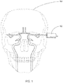
- FIG. 1 illustrates a side view of a prior art TCD probe 102 pressed against a human being's skull 104.
- a TCD probe 102 was manipulated by a human operator (e.g., a skilled sonographer operating a TCD probe), it was not critical to reduce the size of the TCD probe 102.
- FIG. 2 illustrates a robotic headset 106 mounted on a human being's skull 104.
- FIG. 2 illustrates a robotic headset 106 mounted on a human being's skull 104.
- FIG. 3 illustrates a perspective view of a TCD probe 202 mounted in a gimbal 204 for use in a robotic headset 106. While this specification frequently discusses TCD probes, in general, the techniques and devices discussed herein specifically described as using TCD can also be employed in various embodiments using probes for methods such as ultrasound, transcranial color-coded sonography (TCCS), phased arrays, as well as other known ultrasound energy modalities. Additionally, other techniques that use probes that emit or receive energy in the electromagnetic spectrum such as functional Near-Infrared Spectroscopy (fNIRS) or EEG can also be employed.
- fNIRS Near-Infrared Spectroscopy
- the gimbal 204 includes a pivoted support that allows for rotation of an object (e.g., the probe 202), about an axis (e.g., about a single axis).
- the gimbal 204 is a probe hub. Further disclosure regarding the probe hub is described below.
- a data/power cable 206 allows for the flow of electricity to power the TCD probe 202 and the flow of data from the TCD probe 202.
- the gimbal 204 allows the TCD probe 202 to pan and tilt.
- FIG. 4 illustrates an exploded view of the TCD probe 202 connection to the gimbal 204.
- the TCD probe 202 is fastened, typically with glue, to a thrust plate 208.
- the thrust plate 208 has a plurality of legs 210a, 210b, 210c, 210d designed to mount in and align with corresponding receiving holes 212a, 212b (other holes 212c, 212d not shown).
- the thrust plate 208 is secured to the gimbal 204 by snap rings (not shown) on the bottom of the gimbal 204.
- a load cell 214 is fastened, typically with a form to fit counter sunk feature for initial alignment and with glue for stabilization, to the gimbal 204, and is designed to fit between the gimbal 204 and thrust plate 208.
- a load cell 214 is a transducer that is used to translate physical phenomenon into an electrical signal whose magnitude is proportional to, in this case, the force being measured.
- Wires 216 extending from the load cell 214 provide electrical signals (e.g., data and power signals) emanating from the load cell 214 responsive to the force on the load cell 214.
- electrical signals e.g., data and power signals
- a force will also be imparted through the interfacing thrust plate 208 to the load cell 214, which will result in an electrical signal which can be measured.
- FIG. 5 illustrates a perspective cross-sectional view of the of the TCD probe 202 connected to the thrust plate 208, which is in turn in contact with the load cell 214 connected to the gimbal 204.
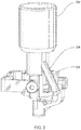
- FIG. 6 illustrates a perspective view of a preferred embodiment of an integrated gimbal TCD probe 300 and FIG. 7 illustrates an elevation view of the integrated gimbal TCD probe 300.
- the integrated gimbal TCD probe 300 reduces the number of components compared to the embodiment of Fig. 4 .
- the integrated gimbal TCD probe 300 has a TCD probe 302 capable of transmitting ultrasound waves into a human being's skull 104. The ultrasound waves are transmitted through the transducer face 303 which is pressed against the skin of a human being's skull 104.
- the TCD probe 302, rather than being cylinder shaped, has a tapered portion 304 adapted to receive a cover (as shown in Fig. 8 ).
- the TCD probe 302 probe body 306 extends to a gimbal mount 314.
- the gimbal mount 314 has a plurality of tapped holes 310a, 310b, designed to mount with and allow for fastening of the gimbal mount 314 to a gimbal interface.
- a data/power cable 312 extends from the gimbal mount 314 of the integrated gimbal TCD probe 300 such that it has proper clearance from the gimbal.
- FIG. 8 illustrates a TCD probe 402 having a shape similar to the integrated gimbal TCD probe 300 shown in FIG. 6 .
- the TCD probe 402 has a tapered portion 404 adapted to receive a cover 406.
- the cover 406 mounts snugly to the tapered portion 404 to prevent a patient's skin from being pinched between the TCD probe 402 and any other mechanism of the robotic headset 106.
- gel is typically placed on a transducer face 408 of the TCD probe 402 to provide improved conductivity between the skin of the patient and the transducer face 408.
- Employing a cover 406 snugly mounted with the tapered portion 404 will act to help prevent gel from moving past the tapered portion into the rest of the mechanism of the robotic headset 106. If gel were to move into the mechanism of the robotic headset 106, the gel may degrade operation of the robotic headset 106 or may require that the robotic headset 106 be cleaned from time to time to remove unwanted gel.
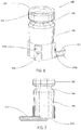
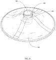
- FIG. 9 illustrates a perspective view of an integrated force center probe 500.
- the integrated force center probe 500 includes a TCD probe 502 capable of transmitting ultrasound waves into a human being's skull 104.
- the TCD probe 502 has a tapered portion 504 adapted to receive a cover (as shown in Fig. 8 ).
- the TCD probe 502 probe body 506 extends to a gimbal mount 514.
- an overmold piece 516 connects the gimbal mount 514 and the probe body 506.
- the gimbal mount 514 has a plurality of tapped holes 510 designed to mount with and allow for fastening of the gimbal mount 514 to a gimbal.
- a data/power cable 512 extends from the gimbal mount 514 of the integrated gimbal TCD probe 500 such that it has proper clearance from the gimbal.
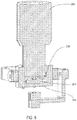
- FIG. 10 illustrates a cross-sectional side view of the integrated force center probe 500.
- a load cell 508 is molded into the bottom of TCD probe 502 having a probe body 506.
- the assembly of the load cell 508 and TCD probe 502 is then molded to gimbal mount 514 such that when the load cell 508 contacts the gimbal mount 514 a specific pre-defined preload is applied to a button 518 on the load cell 508.
- the gimbal mount 514 and probe body 506 are then molded together with an overmold piece 516.
- a data/power cable 512 extends from the gimbal mount 514 of the integrated force center probe 500 such that it has proper clearance from the gimbal.
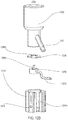
- FIG. 11 illustrates a perspective view of an exploded portion of the integrated force center probe 500 oriented in a direction opposite that of FIG. 10 . This view does not show the gimbal mount 514 or the data/power cable 512.
- Load cell 508 is mounted within a recess or countersink 520 of the probe body 506. Wires 522 extending from the load cell 508 provide electrical signals emanating from the load cell 508 responsive to the force on the load cell 508. The wires 522 exit the probe body 506 through a recess 524 in the probe body 506.
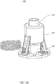
- FIG. 12A illustrates a perspective view of an integrated probe structure 1200 according to various embodiments.
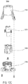
- FIG. 12B illustrates an exploded view of the integrated probe structure 1200 shown in FIG. 12A according to various embodiments.
- FIG. 12C illustrates a perspective cross-sectional view of the integrated probe structure 1200 shown in FIG. 12A according to various embodiments.
- the probe structure 1200 includes a probe 1202, a probe hub or gimbal 1204, a probe seat 1206, and a load cell 1208.
- the probe 1202 includes a first end (e.g., the end that is free and facing empty space) and a second end that is opposite to the first end.
- the first end includes a concave surface that is configured to be adjacent to or contact a scanning surface. The concave surface is configured with a particular pitch to focus generated energy towards the scanning surface.
- the probe structure is a Transcranial Doppler (TCD) apparatus such that the first end of the probe is configured to be adjacent to or contact and align along a human head (e.g., a side of the human head), and the first end of the probe 1202 is configured to provide ultrasound wave emissions from the first end and directed into the human head (e.g., towards the brain).
- TCD Transcranial Doppler
- the probe 1202 is configured to emit other types of waves during operation, such as, but not limited to, infrared waves, x-rays, or the like.
- the second end of the probe 1202 is coupled to the probe seat 1206.
- the probe 1202 includes a hollow 1202A extending though the center of the probe 1202.
- the hollow 1202A includes a threaded cavity-type interface.
- the hollow 1202A allows for alignment amongst the probe 1202, the probe seat 1206, and the load cell 1208.
- the probe seat 1206 includes a circular ridge 1206A defining a through hole 1206B and the circular ridge 1206A extending upwards into the hollow 1202A of the probe 1202.
- the circular ridge 1206A includes a lip defining or housing a through hole, and the lip is fitted to extend upwards from the probe seat 1206.
- the probe seat 1206 is made from any suitable material for transferring the full or almost full force applied to the first end of the probe 1202 to the load cell 1208, such as, but not limited to, a non-metal material (e.g., polyurethane) and the like.
- the probe structure 1200 does not include the probe seat 1206 such that the probe 1202 and the load cell 1208 contact each other.
- the probe seat 1206 is affixed to the probe 1202 through an adhesive layer.
- the adhesive layer may be any suitable material for securely coupling the probe seat 1206 and the probe 1202 together, such as, but not limited to, an epoxy.
- the probe 1202 is secured in the probe seat 1206 by any other suitable connecting means, such as, but not limited to, welding, potting, one or more hooks and latches, one or more separate screws, press fittings, or the like.
- the load cell 1208 is coupled to the probe seat 1206. Accordingly, the probe seat 1206 may also function as a load cell register. In some embodiments, the load cell 1208 is configured to take measurements of pressure or force exerted on the probe 1202. In some embodiments, the load cell 1208 is assembled so as to exhibit a preload. For example, the load cell 1208 may be designed to exhibit and include a preload in a range from about 2 Newtons to about 3 Newtons.
- the load cell 1208 is aligned with and proximate the probe 1202 (e.g., coupled to the probe 1202 via the probe seat 1206), a force exerted against the concave surface of the first end of the probe 1202 (e.g., caused by the concave surface being pressed against a human head), is registered and measured at the load cell 1208.
- the load cell 1208 is a transducer that is used to create an electrical signal whose magnitude is proportional to the force being measured.
- a wire 1212 extending from the load cell 1208 provides electrical signals generated from the load cell 1208, responsive to the force on the load cell 1208 caused by the probe 1202.
- a force will also be imparted through the probe seat 1206 to the load cell 1208, which can be measured and transmitted by the load cell 1208.
- the probe structure 1200 utilizes the measurements of the load cell 1208 to adjust the pressure exerted by the probe 1202 (e.g., by a robotic apparatus attached to the probe structure 1200). For example, in some embodiments, the probe structure 1200 decreases the force exerted against a human head by the probe 1202 when the pressure measured by the load cell 1208 is determined to be relatively high (e.g., the pressure measurement exceeds a predetermined threshold). In some embodiments, the predetermined threshold is user-defined and can be adjusted as desired.
- the load cell 1208 includes a cylindrical protrusion 1208A extending upwards from the load cell 1208.
- the protrusion 1208 passes through the through hole 1206B of the probe seat 1206 and extends into the hollow 1202A (or the threaded cavity-type interface of the hollow 1202A) of the probe 1202. Accordingly, the probe 1202, the probe seat 1206, and the load cell 1208 are capable of remaining aligned such that a maximum amount of forced is transferred from the probe 1202 to the load cell 1208.
- the load cell 1208 is affixed to a bottom inner surface of the probe hub (or gimbal) 1204 through an adhesive layer.
- the adhesive layer may be any suitable material for securely coupling the load cell 1208 and the probe hub 1204 together, such as, but not limited to, an epoxy, potting, and the like.
- the probe hub 1204 provides a plurality of single axis pivoted supports and interfaces with links and motors to provide a pan and tilt about respective Y and X axes.
- the probe hub 1204 is a gimbal as described above.
- the probe hub 1204 has a fitted cavity for receiving and housing a portion of the probe 1202, the probe seat 1206, and the load cell 1208 to provide further security and alignment of the probe structure 1200.
- the cavity of the probe hub (or gimbal) 1204 includes a counter sunk first inner diameter D1 that corresponds to a location of the load cell 1208 when the load cell 1208 is housed within the probe hub 1204.
- the first diameter D1 is substantially equal to (e.g., slightly larger than) an outer diameter of the load cell 1208 such that the load cell 1208 does not shift radially while housed in the probe hub (or gimbal) 1204. Accordingly, the load cell 1208 remains axially aligned with the probe seat 1206 and a shaft end of the probe 1202.
- the cavity of the probe hub 1204 includes a second inner diameter D2 that corresponds to a location of the probe 1202 and the probe seat 1206 when the probe 1202 and the probe seat 1206 are housed within the probe hub 1204.
- the second inner diameter D2 is substantially equal to (e.g., slightly larger than) an outer diameter of the shaft end of the probe 1202 and the probe seat 1206 such that the probe 1202 and the probe seat 1206 do not shift radially while housed in the probe hub 1204. Accordingly, the probe 1202 and the probe seat 1206 remains axially aligned with the load cell 1208.
- the second inner diameter D2 is greater than the first inner diameter D1.
- the probe hub 1204 has a length long enough to encompass and house the load cell 1208 (e.g., entirely), the probe seat 1206 (e.g., entirely), and a portion (e.g., a substantial portion) of the probe 1202.
- the probe hub 1204 is long enough to house approximately 50% of the length of the body of the probe 1202.
- the probe hub 1204 is long enough to house more than 50% of the length of the body of the probe 1202 (e.g., about 55%, 60%, 65%, or more).
- the probe hub 1204 houses less than 50% of the length of the body of the probe 1202 (e.g., about 45%, 40%, 35%, or less).
- the probe hub 1204 house about 33% of the length of the body of the probe 1202.
- the probe hub 1204 includes a lengthwise slot 1204A.
- the slot 1204A may extend along the full length of the body of the probe hub 1204. In other embodiments, the slot 1204A extends along less than the full length of the body of the probe hub 1204.
- the slot 1204A is configured to receive and retain wires and cables originating from the components housed within the probe hub 1204. For example, the slot 1204A receives and retains the wire 1212 originating from the load cell 1208 and a cable 1210 originating from the probe 1202. Accordingly, the wire 1212 and the cable 1210 can be aligned and secured (e.g., during assembly and outside of the probe hub or gimbal 1204) so that they do not become an obstacle during assembly or operation of the probe structure 1200.
- the wire 1212 remains static in the slot 1204A, while the cable 1210 is configured to move within the slot 1204A (e.g., flex or otherwise move along the length of the slot 1204A).
- the probe hub 1204 further includes a gimbal interface 1214 for attaching to gimbal linkages that can control the probe structure 1200.
- FIG. 13A illustrates a perspective view of an integrated probe structure 1300 according to various embodiments.
- FIG. 13B illustrates a transparent probe housing in a perspective view of the integrated probe structure 1300 shown in FIG. 13A according to various embodiments.
- FIG. 13C illustrates an exploded view of the integrated probe structure 1300 shown in FIG. 13A according to various embodiments.
- the probe structure 1300 includes a probe housing 1302, a probe 1304, an interconnection structure 1306, and a load cell 1308.
- the probe structure 1300 includes an end effector, for example, used in conjunction with a robot arm (e.g., a 6-axis robot arm).
- the probe housing 1302 covers and houses the probe 1304, the interconnection structure 1306, and the load cell 1308.
- the probe 1304 extends through a top opening of the probe housing 1302.
- the interconnection structure 1306 provides the framework of the probe structure 1300 for securing the components together.
- the load cell 1308 is located adjacent to the probe 1304 (e.g., directly underneath the probe 1304).
- the probe structure 1300 can be used in connection with a robotic arm (e.g., a robotic arm including multiple degrees of freedom, such as, but not limited to, six degrees of freedom).
- the present disclosure illustrates and describes an integrated probe system including a load cell for detecting force exerted against a probe in a single axis (e.g., along an axis that is perpendicular to the upper surface of the probe facing a scanning surface)
- the load cell and the integrated probe system may be configured to detect forces in a plurality of axes.
- the integrated probe system may be configured to detect force exerted against the probe along two axes, three axes, four axes, five axes, or six axes.
- the probe is continuously adjusted to maintain a normal position along a scanning surface using a load cell that detects force along a plurality of axes (e.g., along six different axes).
- the terms “approximately,” “substantially,” “substantial” and “about” are used to describe and account for small variations. When used in conjunction with an event or circumstance, the terms can refer to instances in which the event or circumstance occurs precisely as well as instances in which the event or circumstance occurs to a close approximation.
- the terms can refer to a range of variation less than or equal to ⁇ 10% of that numerical value, such as less than or equal to ⁇ 5%, less than or equal to ⁇ 4%, less than or equal to ⁇ 3%, less than or equal to ⁇ 2%, less than or equal to ⁇ 1%, less than or equal to ⁇ 0.5%, less than or equal to ⁇ 0.1%, or less than or equal to ⁇ 0.05%.
- two numerical values can be deemed to be "substantially" the same or equal if a difference between the values is less than or equal to ⁇ 10% of an average of the values, such as less than or equal to ⁇ 5%, less than or equal to ⁇ 4%, less than or equal to ⁇ 3%, less than or equal to ⁇ 2%, less than or equal to ⁇ 1%, less than or equal to ⁇ 0.5%, less than or equal to ⁇ 0.1%, or less than or equal to ⁇ 0.05%.
- first element may be directly coupled to the second element or may be indirectly coupled to the second element via a third element.
Description
- Subject matter described herein relates generally to medical devices, and more particularly to a probe for diagnosing medical conditions.
- For devices utilizing a probe (e.g., an automated Transcranial Doppler (TCD) device), there exist patient safety concerns related to the placement and alignment of TCD probes against a human being's skull. This safety concern exists within the structure of an automated robotic headset or manual operation of TCD probes. In existing solutions, either manual placement of the TCD probe or the complexity of the TCD probe mechanism may not be optimal. Currently there is no method to observe the amount of pressure or force exerted on a patient's temporal window or skull and thus there are no mediums to monitor patient discomfort during an automated or manual TCD probe placement.
-
JP H0571763U EP 0403807 A2 disclose probes for industrial flaw detection.US 2012/108967 A1 discloses an apparatus for sealing vascular punctures.US 2005/004457 A1 discloses a method for taking ultrasound measurements from long bones.US 2015/297176 A1 discloses a head frame apparatus comprising automated robotics configured to position a probe structure with respect to a subject and a strain gauge provided within the probe. - The invention is defined by independent claim 1. Further embodiments of the invention are defined by the dependent claims.
-
-
FIG. 1 illustrates a perspective view of a TCD probe previously known in the art. -
FIG. 2 illustrates a robotic headset for incorporating a TCD probe. -
FIG. 3 illustrates a perspective view of an integrated TCD probe structure according to various embodiments. -
FIG. 4 an exploded view of an integrated TCD probe structure according to various embodiments. -
FIG. 5 illustrates a side cross-sectional view of an integrated TCD probe structure according to various embodiments. -
FIG. 6 illustrates a perspective view of an integrated gimbal probe structure according to various embodiments. -
FIG. 7 illustrates a side view of an integrated gimbal probe structure according to various embodiments. -
FIG. 8 illustrates a perspective view of a TCD probe adapted for use with an integrated gimbal probe structure with a cover according to various embodiments. -
FIG. 9 illustrates a perspective view of an integrated force center probe according to various embodiments. -
FIG. 10 illustrates a side cross-sectional view of a TCD probe adapted for use with a three piece integrated gimbal probe structure according to various embodiments. -
FIG. 11 illustrates a perspective exploded view of a TCD probe adapted for use with an integrated gimbal probe structure integrated with a cover according to various embodiments. -
FIG. 12A illustrates a perspective view of an integrated probe structure according to various embodiments. -
FIG. 12B illustrates an exploded view of the integrated probe structure shown inFIG. 12A according to various embodiments. -
FIG. 12C illustrates a perspective cross-sectional view of the integrated probe structure shown inFIG. 12A according to various embodiments. -
FIG. 13A illustrates a perspective view of an integrated probe structure according to various embodiments. -
FIG. 13B illustrates a transparent perspective view of the integrated probe structure shown inFIG. 13A according to various embodiments. -
FIG. 13C illustrates an exploded view of the integrated probe structure shown inFIG. 13A according to various embodiments. - The detailed description set forth below in connection with the appended drawings is intended as a description of various configurations and is not intended to represent the only configurations in which the concepts described herein may be practiced. The detailed description includes specific details for providing a thorough understanding of various concepts. However, it will be apparent to those skilled in the art that these concepts may be practiced without these specific details. In some instances, well-known structures and components are shown in block diagram form in order to avoid obscuring such concepts.
-
FIG. 1 illustrates a side view of a prior art TCD probe 102 pressed against a human being'sskull 104. In the prior art, when a TCD probe 102 was manipulated by a human operator (e.g., a skilled sonographer operating a TCD probe), it was not critical to reduce the size of the TCD probe 102. -
FIG. 2 illustrates a robotic headset 106 mounted on a human being'sskull 104. To facilitate automated TCD scans without the use of a human operator manipulating a TCD probe, it would be advantageous to reduce the size of a TCD probe so that it would fit within a reasonably sized headset 106. -
FIG. 3 illustrates a perspective view of aTCD probe 202 mounted in agimbal 204 for use in a robotic headset 106. While this specification frequently discusses TCD probes, in general, the techniques and devices discussed herein specifically described as using TCD can also be employed in various embodiments using probes for methods such as ultrasound, transcranial color-coded sonography (TCCS), phased arrays, as well as other known ultrasound energy modalities. Additionally, other techniques that use probes that emit or receive energy in the electromagnetic spectrum such as functional Near-Infrared Spectroscopy (fNIRS) or EEG can also be employed. In some embodiments, thegimbal 204 includes a pivoted support that allows for rotation of an object (e.g., the probe 202), about an axis (e.g., about a single axis). In some embodiments, thegimbal 204 is a probe hub. Further disclosure regarding the probe hub is described below. A data/power cable 206 allows for the flow of electricity to power theTCD probe 202 and the flow of data from theTCD probe 202. Thegimbal 204 allows theTCD probe 202 to pan and tilt. -
FIG. 4 illustrates an exploded view of theTCD probe 202 connection to thegimbal 204. To allow for connection of theTCD probe 202 to thegimbal 204, theTCD probe 202 is fastened, typically with glue, to a thrust plate 208. The thrust plate 208 has a plurality of legs 210a, 210b, 210c, 210d designed to mount in and align with corresponding receiving holes 212a, 212b (other holes 212c, 212d not shown). The thrust plate 208 is secured to thegimbal 204 by snap rings (not shown) on the bottom of thegimbal 204. Other methods of fastening known to those of skill in the art may also be employed, such as, but not limited to, interfacing (e.g., counter sunk features). Aload cell 214 is fastened, typically with a form to fit counter sunk feature for initial alignment and with glue for stabilization, to thegimbal 204, and is designed to fit between thegimbal 204 and thrust plate 208. As is known in the art, aload cell 214 is a transducer that is used to translate physical phenomenon into an electrical signal whose magnitude is proportional to, in this case, the force being measured. Wires 216 extending from theload cell 214 provide electrical signals (e.g., data and power signals) emanating from theload cell 214 responsive to the force on theload cell 214. In operation, when theTCD probe 202 is pressed against a human being'sskull 104, a force will also be imparted through the interfacing thrust plate 208 to theload cell 214, which will result in an electrical signal which can be measured. -
FIG. 5 illustrates a perspective cross-sectional view of the of theTCD probe 202 connected to the thrust plate 208, which is in turn in contact with theload cell 214 connected to thegimbal 204. -
FIG. 6 illustrates a perspective view of a preferred embodiment of an integratedgimbal TCD probe 300 andFIG. 7 illustrates an elevation view of the integratedgimbal TCD probe 300. The integratedgimbal TCD probe 300 reduces the number of components compared to the embodiment ofFig. 4 . The integratedgimbal TCD probe 300 has aTCD probe 302 capable of transmitting ultrasound waves into a human being'sskull 104. The ultrasound waves are transmitted through thetransducer face 303 which is pressed against the skin of a human being'sskull 104. TheTCD probe 302, rather than being cylinder shaped, has a taperedportion 304 adapted to receive a cover (as shown inFig. 8 ). Beyond the taperedportion 304, theTCD probe 302probe body 306 extends to agimbal mount 314. Thegimbal mount 314 has a plurality of tapped holes 310a, 310b, designed to mount with and allow for fastening of thegimbal mount 314 to a gimbal interface. A data/power cable 312 extends from thegimbal mount 314 of the integratedgimbal TCD probe 300 such that it has proper clearance from the gimbal. -
FIG. 8 illustrates aTCD probe 402 having a shape similar to the integratedgimbal TCD probe 300 shown inFIG. 6 . TheTCD probe 402 has a tapered portion 404 adapted to receive a cover 406. The cover 406 mounts snugly to the tapered portion 404 to prevent a patient's skin from being pinched between theTCD probe 402 and any other mechanism of the robotic headset 106. Further, in operation, gel is typically placed on atransducer face 408 of theTCD probe 402 to provide improved conductivity between the skin of the patient and thetransducer face 408. Employing a cover 406 snugly mounted with the tapered portion 404 will act to help prevent gel from moving past the tapered portion into the rest of the mechanism of the robotic headset 106. If gel were to move into the mechanism of the robotic headset 106, the gel may degrade operation of the robotic headset 106 or may require that the robotic headset 106 be cleaned from time to time to remove unwanted gel. -
FIG. 9 illustrates a perspective view of an integratedforce center probe 500. The integratedforce center probe 500 includes aTCD probe 502 capable of transmitting ultrasound waves into a human being'sskull 104. TheTCD probe 502 has a taperedportion 504 adapted to receive a cover (as shown inFig. 8 ). Below the taperedportion 504, theTCD probe 502probe body 506 extends to a gimbal mount 514. Between the gimbal mount 514 and theprobe body 506, an overmold piece 516 connects the gimbal mount 514 and theprobe body 506. The gimbal mount 514 has a plurality of tapped holes 510 designed to mount with and allow for fastening of the gimbal mount 514 to a gimbal. A data/power cable 512 extends from the gimbal mount 514 of the integratedgimbal TCD probe 500 such that it has proper clearance from the gimbal. -
FIG. 10 illustrates a cross-sectional side view of the integratedforce center probe 500. Aload cell 508 is molded into the bottom ofTCD probe 502 having aprobe body 506. The assembly of theload cell 508 andTCD probe 502 is then molded to gimbal mount 514 such that when theload cell 508 contacts the gimbal mount 514 a specific pre-defined preload is applied to a button 518 on theload cell 508. The gimbal mount 514 andprobe body 506 are then molded together with an overmold piece 516. A data/power cable 512 extends from the gimbal mount 514 of the integratedforce center probe 500 such that it has proper clearance from the gimbal. -
FIG. 11 illustrates a perspective view of an exploded portion of the integratedforce center probe 500 oriented in a direction opposite that ofFIG. 10 . This view does not show the gimbal mount 514 or the data/power cable 512.Load cell 508 is mounted within a recess or countersink 520 of theprobe body 506.Wires 522 extending from theload cell 508 provide electrical signals emanating from theload cell 508 responsive to the force on theload cell 508. Thewires 522 exit theprobe body 506 through a recess 524 in theprobe body 506. -
FIG. 12A illustrates a perspective view of anintegrated probe structure 1200 according to various embodiments.FIG. 12B illustrates an exploded view of theintegrated probe structure 1200 shown inFIG. 12A according to various embodiments.FIG. 12C illustrates a perspective cross-sectional view of theintegrated probe structure 1200 shown inFIG. 12A according to various embodiments. - Referring to
FIGS. 12A-12C , theprobe structure 1200 includes aprobe 1202, a probe hub orgimbal 1204, aprobe seat 1206, and aload cell 1208. In some embodiments, theprobe 1202 includes a first end (e.g., the end that is free and facing empty space) and a second end that is opposite to the first end. In some embodiments, the first end includes a concave surface that is configured to be adjacent to or contact a scanning surface. The concave surface is configured with a particular pitch to focus generated energy towards the scanning surface. In some embodiments, the probe structure is a Transcranial Doppler (TCD) apparatus such that the first end of the probe is configured to be adjacent to or contact and align along a human head (e.g., a side of the human head), and the first end of theprobe 1202 is configured to provide ultrasound wave emissions from the first end and directed into the human head (e.g., towards the brain). In other embodiments, theprobe 1202 is configured to emit other types of waves during operation, such as, but not limited to, infrared waves, x-rays, or the like. - In some embodiments, the second end of the
probe 1202 is coupled to theprobe seat 1206. Theprobe 1202 includes a hollow 1202A extending though the center of theprobe 1202. In some embodiments, the hollow 1202A includes a threaded cavity-type interface. The hollow 1202A allows for alignment amongst theprobe 1202, theprobe seat 1206, and theload cell 1208. For example, theprobe seat 1206 includes acircular ridge 1206A defining a throughhole 1206B and thecircular ridge 1206A extending upwards into the hollow 1202A of theprobe 1202. Thecircular ridge 1206A includes a lip defining or housing a through hole, and the lip is fitted to extend upwards from theprobe seat 1206. While theprobe 1202 is coupled or attached to theprobe seat 1206 at one side of theprobe seat 1206, theload cell 1208 is coupled or attached to the opposite side of theprobe seat 1206 such that theprobe seat 1206 is interposed between theprobe 1202 and theload cell 1208. Accordingly, in some embodiments, theprobe seat 1206 is made from any suitable material for transferring the full or almost full force applied to the first end of theprobe 1202 to theload cell 1208, such as, but not limited to, a non-metal material (e.g., polyurethane) and the like. In some embodiments, theprobe structure 1200 does not include theprobe seat 1206 such that theprobe 1202 and theload cell 1208 contact each other. - In some embodiments, the
probe seat 1206 is affixed to theprobe 1202 through an adhesive layer. The adhesive layer may be any suitable material for securely coupling theprobe seat 1206 and theprobe 1202 together, such as, but not limited to, an epoxy. In other embodiments, theprobe 1202 is secured in theprobe seat 1206 by any other suitable connecting means, such as, but not limited to, welding, potting, one or more hooks and latches, one or more separate screws, press fittings, or the like. - In some embodiments, the
load cell 1208 is coupled to theprobe seat 1206. Accordingly, theprobe seat 1206 may also function as a load cell register. In some embodiments, theload cell 1208 is configured to take measurements of pressure or force exerted on theprobe 1202. In some embodiments, theload cell 1208 is assembled so as to exhibit a preload. For example, theload cell 1208 may be designed to exhibit and include a preload in a range from about 2 Newtons to about 3 Newtons. In some embodiments, because theload cell 1208 is aligned with and proximate the probe 1202 (e.g., coupled to theprobe 1202 via the probe seat 1206), a force exerted against the concave surface of the first end of the probe 1202 (e.g., caused by the concave surface being pressed against a human head), is registered and measured at theload cell 1208. - In some embodiments, the
load cell 1208 is a transducer that is used to create an electrical signal whose magnitude is proportional to the force being measured. In some embodiments, awire 1212 extending from theload cell 1208 provides electrical signals generated from theload cell 1208, responsive to the force on theload cell 1208 caused by theprobe 1202. During operation, in some embodiments, when theprobe 1202 is pressed against a human skull, a force will also be imparted through theprobe seat 1206 to theload cell 1208, which can be measured and transmitted by theload cell 1208. - Accordingly, in some embodiments, the
probe structure 1200 utilizes the measurements of theload cell 1208 to adjust the pressure exerted by the probe 1202 (e.g., by a robotic apparatus attached to the probe structure 1200). For example, in some embodiments, theprobe structure 1200 decreases the force exerted against a human head by theprobe 1202 when the pressure measured by theload cell 1208 is determined to be relatively high (e.g., the pressure measurement exceeds a predetermined threshold). In some embodiments, the predetermined threshold is user-defined and can be adjusted as desired. - In some embodiments, the
load cell 1208 includes acylindrical protrusion 1208A extending upwards from theload cell 1208. Theprotrusion 1208 passes through the throughhole 1206B of theprobe seat 1206 and extends into the hollow 1202A (or the threaded cavity-type interface of the hollow 1202A) of theprobe 1202. Accordingly, theprobe 1202, theprobe seat 1206, and theload cell 1208 are capable of remaining aligned such that a maximum amount of forced is transferred from theprobe 1202 to theload cell 1208. In some embodiments, theload cell 1208 is affixed to a bottom inner surface of the probe hub (or gimbal) 1204 through an adhesive layer. The adhesive layer may be any suitable material for securely coupling theload cell 1208 and theprobe hub 1204 together, such as, but not limited to, an epoxy, potting, and the like. - In some embodiments, the
probe hub 1204 provides a plurality of single axis pivoted supports and interfaces with links and motors to provide a pan and tilt about respective Y and X axes. In some embodiments, theprobe hub 1204 is a gimbal as described above. In some embodiments, theprobe hub 1204 has a fitted cavity for receiving and housing a portion of theprobe 1202, theprobe seat 1206, and theload cell 1208 to provide further security and alignment of theprobe structure 1200. The cavity of the probe hub (or gimbal) 1204 includes a counter sunk first inner diameter D1 that corresponds to a location of theload cell 1208 when theload cell 1208 is housed within theprobe hub 1204. The first diameter D1 is substantially equal to (e.g., slightly larger than) an outer diameter of theload cell 1208 such that theload cell 1208 does not shift radially while housed in the probe hub (or gimbal) 1204. Accordingly, theload cell 1208 remains axially aligned with theprobe seat 1206 and a shaft end of theprobe 1202. - Similarly, the cavity of the
probe hub 1204 includes a second inner diameter D2 that corresponds to a location of theprobe 1202 and theprobe seat 1206 when theprobe 1202 and theprobe seat 1206 are housed within theprobe hub 1204. The second inner diameter D2 is substantially equal to (e.g., slightly larger than) an outer diameter of the shaft end of theprobe 1202 and theprobe seat 1206 such that theprobe 1202 and theprobe seat 1206 do not shift radially while housed in theprobe hub 1204. Accordingly, theprobe 1202 and theprobe seat 1206 remains axially aligned with theload cell 1208. In some embodiments, the second inner diameter D2 is greater than the first inner diameter D1. - In some embodiments, the probe hub (or gimbal) 1204 has a length long enough to encompass and house the load cell 1208 (e.g., entirely), the probe seat 1206 (e.g., entirely), and a portion (e.g., a substantial portion) of the
probe 1202. In some embodiments, theprobe hub 1204 is long enough to house approximately 50% of the length of the body of theprobe 1202. In other embodiments, theprobe hub 1204 is long enough to house more than 50% of the length of the body of the probe 1202 (e.g., about 55%, 60%, 65%, or more). In other embodiments, theprobe hub 1204 houses less than 50% of the length of the body of the probe 1202 (e.g., about 45%, 40%, 35%, or less). In particular embodiments, theprobe hub 1204 house about 33% of the length of the body of theprobe 1202. - In some embodiments, the
probe hub 1204 includes a lengthwise slot 1204A. The slot 1204A may extend along the full length of the body of theprobe hub 1204. In other embodiments, the slot 1204A extends along less than the full length of the body of theprobe hub 1204. The slot 1204A is configured to receive and retain wires and cables originating from the components housed within theprobe hub 1204. For example, the slot 1204A receives and retains thewire 1212 originating from theload cell 1208 and acable 1210 originating from theprobe 1202. Accordingly, thewire 1212 and thecable 1210 can be aligned and secured (e.g., during assembly and outside of the probe hub or gimbal 1204) so that they do not become an obstacle during assembly or operation of theprobe structure 1200. In some embodiments, thewire 1212 remains static in the slot 1204A, while thecable 1210 is configured to move within the slot 1204A (e.g., flex or otherwise move along the length of the slot 1204A). In some embodiments, theprobe hub 1204 further includes agimbal interface 1214 for attaching to gimbal linkages that can control theprobe structure 1200. -
FIG. 13A illustrates a perspective view of anintegrated probe structure 1300 according to various embodiments.FIG. 13B illustrates a transparent probe housing in a perspective view of theintegrated probe structure 1300 shown inFIG. 13A according to various embodiments.FIG. 13C illustrates an exploded view of theintegrated probe structure 1300 shown inFIG. 13A according to various embodiments. - The
probe structure 1300 includes aprobe housing 1302, aprobe 1304, aninterconnection structure 1306, and aload cell 1308. In some embodiments, theprobe structure 1300 includes an end effector, for example, used in conjunction with a robot arm (e.g., a 6-axis robot arm). Theprobe housing 1302 covers and houses theprobe 1304, theinterconnection structure 1306, and theload cell 1308. Theprobe 1304 extends through a top opening of theprobe housing 1302. Theinterconnection structure 1306 provides the framework of theprobe structure 1300 for securing the components together. Theload cell 1308 is located adjacent to the probe 1304 (e.g., directly underneath the probe 1304). Theprobe structure 1300 can be used in connection with a robotic arm (e.g., a robotic arm including multiple degrees of freedom, such as, but not limited to, six degrees of freedom). - Although the present disclosure illustrates and describes an integrated probe system including a load cell for detecting force exerted against a probe in a single axis (e.g., along an axis that is perpendicular to the upper surface of the probe facing a scanning surface), in some embodiments, the load cell and the integrated probe system may be configured to detect forces in a plurality of axes. For example, the integrated probe system may be configured to detect force exerted against the probe along two axes, three axes, four axes, five axes, or six axes. In some embodiments, the probe is continuously adjusted to maintain a normal position along a scanning surface using a load cell that detects force along a plurality of axes (e.g., along six different axes).
- As used herein, the terms "approximately," "substantially," "substantial" and "about" are used to describe and account for small variations. When used in conjunction with an event or circumstance, the terms can refer to instances in which the event or circumstance occurs precisely as well as instances in which the event or circumstance occurs to a close approximation. For example, when used in conjunction with a numerical value, the terms can refer to a range of variation less than or equal to ±10% of that numerical value, such as less than or equal to ±5%, less than or equal to ±4%, less than or equal to ±3%, less than or equal to ±2%, less than or equal to ±1%, less than or equal to ±0.5%, less than or equal to ±0.1%, or less than or equal to ±0.05%. For example, two numerical values can be deemed to be "substantially" the same or equal if a difference between the values is less than or equal to ±10% of an average of the values, such as less than or equal to ±5%, less than or equal to ±4%, less than or equal to ±3%, less than or equal to ±2%, less than or equal to ±1%, less than or equal to ±0.5%, less than or equal to ±0.1%, or less than or equal to ±0.05%.
- The above used terms, including "attached," "connected," "secured," and the like are used interchangeably. In addition, while certain embodiments have been described to include a first element as being "coupled" (or "attached," "connected," "fastened," etc.) to a second element, the first element may be directly coupled to the second element or may be indirectly coupled to the second element via a third element.
Claims (14)
- An ultrasound system for use on a subject, the system comprising:a robotic headset (106) configured to be worn by the subject, the robotic headset comprising automated robotics configured to position a probe structure (1200) with respect to the subject;the probe structure comprising:a probe (1202) configured to emit acoustic energy and that defines a hollow (1202A);a load cell (1208) underneath and aligned with the probe and that comprises a protrusion (1208A), wherein the load cell is configured to take a force reading indicating an amount of force exerted against the probe, wherein the automated robotics are further configured to adjust the amount of force exerted against the subject by the probe in response to the force reading, and wherein the hollow of the probe receives the protrusion of the load cell for securing the load cell and the probe together ; anda probe hub (1204) including a cavity for receiving the probe and the load cell.
- The system of claim 1, wherein the probe structure further comprises a probe seat (1206) interposed between the probe and the load cell
- The system of claim 1, wherein the probe hub includes a lengthwise slot
- The system of claim 3, wherein the lengthwise slot is configured to align and retain a cable connected to the probe and a wire connected to the load cell.
- The system of claim 4, wherein the wire connected to the load cell is held statically within the lengthwise slot while the cable of the probe is configured to move along the lengthwise slot.
- The system of claim 1, the probe structure further comprising an adhesive layer between the load cell and a bottom of the cavity of the probe hub.
- The system of claim 1, the probe structure further comprising a probe seat interposed between the probe and the load cell and an adhesive layer between the probe and the probe seat.
- The system of claim 1, wherein the probe structure further comprises a probe seat interposed between the probe and the load cell, wherein the probe seat has a through hole such that the protrusion of the load cell threads through the through hole and the hollow of the probe.
- The system of claim 1, wherein the probe hub is configured to house the load cell and a portion of the probe.
- The system of claim 9, wherein the cavity of the probe hub includes an inner diameter that is substantially equal to an outer diameter of the portion of the probe.
- The system of claim 9, wherein the cavity of the probe hub includes a first inner diameter corresponding to a location of the portion of the probe housed within the cavity and a second inner diameter corresponding to a location of the load cell housed within the cavity, the first inner diameter being different from the second inner diameter.
- The system of claim 11, wherein the first inner diameter is greater than the second inner diameter.
- The system of claim 1, wherein the load cell is configured to detect forces exerted against the probe along a plurality of axes.
- The system of claim 1, wherein the automated robotics are configured to decrease the amount of force exerted against the subject in response to the force reading being above a first threshold.
Applications Claiming Priority (3)
| Application Number | Priority Date | Filing Date | Title |
|---|---|---|---|
| US201662275192P | 2016-01-05 | 2016-01-05 | |
| US201662332133P | 2016-05-05 | 2016-05-05 | |
| PCT/US2017/012365 WO2017120361A1 (en) | 2016-01-05 | 2017-01-05 | Integrated probe structure |
Publications (3)
| Publication Number | Publication Date |
|---|---|
| EP3399920A1 EP3399920A1 (en) | 2018-11-14 |
| EP3399920A4 EP3399920A4 (en) | 2019-08-14 |
| EP3399920B1 true EP3399920B1 (en) | 2020-11-04 |
Family
ID=59236047
Family Applications (1)
| Application Number | Title | Priority Date | Filing Date |
|---|---|---|---|
| EP17736353.8A Active EP3399920B1 (en) | 2016-01-05 | 2017-01-05 | Integrated probe structure |
Country Status (5)
| Country | Link |
|---|---|
| US (3) | US10617388B2 (en) |
| EP (1) | EP3399920B1 (en) |
| JP (1) | JP2019500155A (en) |
| CN (1) | CN108778141A (en) |
| WO (1) | WO2017120361A1 (en) |
Families Citing this family (10)
| Publication number | Priority date | Publication date | Assignee | Title |
|---|---|---|---|---|
| CN107635472A (en) | 2015-06-19 | 2018-01-26 | 神经系统分析公司 | Transcranial doppler detector |
| US10617388B2 (en) | 2016-01-05 | 2020-04-14 | Neural Analytics, Inc. | Integrated probe structure |
| US11589836B2 (en) | 2016-01-05 | 2023-02-28 | Novasignal Corp. | Systems and methods for detecting neurological conditions |
| CN108778140A (en) | 2016-01-05 | 2018-11-09 | 神经系统分析公司 | System and method for determining clinical indication |
| EP3592206A4 (en) * | 2017-03-06 | 2020-11-18 | Neural Analytics, Inc. | Headset system |
| AU2018380542B2 (en) * | 2017-12-08 | 2022-12-01 | Neurasignal, Inc. | Systems and methods for gel management |
| WO2019133907A1 (en) * | 2017-12-29 | 2019-07-04 | Neural Analytics, Inc. | Probe structure |
| WO2019200001A1 (en) | 2018-04-10 | 2019-10-17 | Cerenetex, Inc. | Systems and methods for the identification of medical conditions, and determination of appropriate therapies, by passively detecting acoustic signals |
| WO2019199334A1 (en) * | 2018-04-13 | 2019-10-17 | Neural Analytics, Inc. | Enclosure for device including probe |
| FR3103551B1 (en) | 2019-11-27 | 2021-12-17 | Commissariat Energie Atomique | A method of manufacturing a detection device comprising a direct bonding step of a thin sealing layer provided with a getter material |
Family Cites Families (289)
| Publication number | Priority date | Publication date | Assignee | Title |
|---|---|---|---|---|
| CA973632A (en) | 1973-05-29 | 1975-08-26 | Arthur C. Hudson | Echoencephalograph |
| US3841308A (en) | 1973-10-15 | 1974-10-15 | Medical Evaluation Devices & I | Distally valved catheter device |
| JPS52126979A (en) | 1976-04-16 | 1977-10-25 | Aloka Co Ltd | Sector scanning system |
| US4205687A (en) | 1977-07-29 | 1980-06-03 | Diagnostic Electronics Corporation | Color coded blood flow velocity display equipment |
| US4204547A (en) | 1978-11-13 | 1980-05-27 | Allocca John A | Method and apparatus for noninvasive monitoring of intracranial pressure |
| US4483344A (en) | 1980-12-30 | 1984-11-20 | Atkov Oleg J | Device for positioning cardiographic sensor |
| NO150015C (en) | 1981-11-13 | 1984-08-08 | Vingmed As | METHOD OF BLOOD FLOW SPEED MEASUREMENT WITH ULTRO SOUND, COMBINED WITH ECO-AMPLITUDE IMAGE, FOR THE INVESTIGATION OF LIVING BIOLOGICAL STRUCTURES |
| US4413629A (en) | 1982-04-22 | 1983-11-08 | Cryomedics, Inc. | Portable ultrasonic Doppler System |
| US4759374A (en) | 1985-05-06 | 1988-07-26 | American Telephone And Telegraph Company And At&T Bell Laboratories | Non-invasive blood flow measurements utilizing cardiac cycle synchronization |
| US4819648A (en) | 1985-10-28 | 1989-04-11 | The Johns Hopkins University | Non-invasive electromagnetic technique for monitoring time-trends of physiological changes at a particular location in the brain |
| GB8622671D0 (en) | 1986-09-19 | 1986-10-22 | Marchbanks R J | Intracranial fluid pressure monitoring |
| JPS6382623A (en) | 1986-09-27 | 1988-04-13 | 日立建機株式会社 | Apparatus for recording intracranial pressure |
| FR2606625B1 (en) | 1986-11-19 | 1991-02-22 | Brion Richard | PROBE HOLDER FOR FIXING AN ECHOGRAPHY PROBE ON A MEASUREMENT AREA |
| US4815705A (en) | 1986-11-27 | 1989-03-28 | Toyoda Gosei Co., Ltd. | Valve body |
| JPH02114008A (en) | 1988-01-30 | 1990-04-26 | Hiroshi Tanaka | Nonslip material structure for grounding portion of tire chainlike nonslip tool enveloping tire surface and periphery |
| FR2626773A1 (en) | 1988-02-05 | 1989-08-11 | Puy Philippe | ECHOGRAPHIC PROBE SUPPORT, IN PARTICULAR ECHOCARDIOGRAPHIC PROBE |
| US4951653A (en) | 1988-03-02 | 1990-08-28 | Laboratory Equipment, Corp. | Ultrasound brain lesioning system |
| US4930513A (en) | 1988-07-26 | 1990-06-05 | U.S. Philips Corporation | Two dimensional processing of pulsed Doppler signals |
| US5040540A (en) | 1988-08-24 | 1991-08-20 | Nims, Inc. | Method and apparatus for non-invasive monitoring of central venous pressure, and improved transducer therefor |
| JP2613654B2 (en) | 1989-06-22 | 1997-05-28 | 矢吉 肥後 | Ultrasonic testing |
| JP3086693B2 (en) | 1989-07-06 | 2000-09-11 | 株式会社東芝 | Ultrasound diagnostic equipment |
| FR2650071B1 (en) | 1989-07-20 | 1991-09-27 | Asulab Sa | PROCESS FOR PROCESSING AN ELECTRICAL SIGNAL |
| US5384725A (en) | 1990-05-18 | 1995-01-24 | Yale University | Method and apparatus for encoding and decoding using wavelet-packets |
| US5074310A (en) | 1990-07-31 | 1991-12-24 | Mick Edwin C | Method and apparatus for the measurement of intracranial pressure |
| EP0508205B1 (en) | 1991-04-09 | 1996-01-17 | Hewlett-Packard Company | System for hybrid position and force control |
| JPH0571763U (en) * | 1991-08-29 | 1993-09-28 | 鈴幸商事株式会社 | Ultrasonic flaw detection probe with pressing force sensor |
| US7497828B1 (en) | 1992-01-10 | 2009-03-03 | Wilk Ultrasound Of Canada, Inc. | Ultrasonic medical device and associated method |
| US6358239B1 (en) | 1992-01-24 | 2002-03-19 | I-Flow Corporation | Platen pump |
| US5409010A (en) | 1992-05-19 | 1995-04-25 | Board Of Regents Of The University Of Washington | Vector doppler medical devices for blood velocity studies |
| US5348015A (en) | 1992-09-17 | 1994-09-20 | Applied Physiology And Medicine | Method and apparatus for ultrasonically detecting, counting and/or characterizing emboli |
| JP3453415B2 (en) | 1992-12-22 | 2003-10-06 | コーニンクレッカ フィリップス エレクトロニクス エヌ ヴィ | Apparatus and method for measuring elasticity of artery by ultrasonic echography |
| DE9422172U1 (en) | 1993-04-26 | 1998-08-06 | Univ St Louis | Specify the location of a surgical probe |
| WO1995002361A1 (en) | 1993-07-15 | 1995-01-26 | Zimmer Stevan D | Doppler ultrasound trigger for use with mr |
| US5388583A (en) | 1993-09-01 | 1995-02-14 | Uab Vittamed | Method and apparatus for non-invasively deriving and indicating of dynamic characteristics of the human and animal intracranial media |
| DE9314075U1 (en) | 1993-09-17 | 1994-01-20 | Dwl Elektron Systeme Gmbh | Device for receiving at least one sonographic probe |
| US5409005A (en) | 1993-10-07 | 1995-04-25 | Medasonics, Inc. | Transcranial doppler probe wheel and track/bar fixation assembly |
| US5379770A (en) | 1993-12-21 | 1995-01-10 | Nicolet Biomedical, Inc. | Method and apparatus for transcranial doppler sonography |
| US5363849A (en) | 1994-01-26 | 1994-11-15 | Cardiovascular Imaging Systems, Inc. | Enhancing intravascular ultrasonic blood vessel image |
| JPH07299066A (en) | 1994-05-10 | 1995-11-14 | Aloka Co Ltd | Ultrasonic probe |
| US5421565A (en) | 1994-08-11 | 1995-06-06 | General Motors Corporation | Suspension spring insulator |
| US5617873A (en) | 1994-08-25 | 1997-04-08 | The United States Of America As Represented By The Administrator, Of The National Aeronautics And Space Administration | Non-invasive method and apparatus for monitoring intracranial pressure and pressure volume index in humans |
| AU4600496A (en) | 1994-12-30 | 1996-07-24 | Acuson Corporation | Adaptive temporal filtering to enhance fluid flow or tissue motion imaging |
| DE19514796C1 (en) | 1995-04-21 | 1996-09-19 | Bernhard Dr Med Loew | Ophthalmodynamometer and method for operating the same |
| US6117089A (en) | 1995-04-25 | 2000-09-12 | The Regents Of The University Of California | Method for noninvasive intracranial pressure measurement |
| US5860929A (en) | 1996-06-07 | 1999-01-19 | The Regents Of The University Of Michigan | Fractional moving blood volume estimation with power doppler ultrasound |
| US6544193B2 (en) | 1996-09-04 | 2003-04-08 | Marcio Marc Abreu | Noninvasive measurement of chemical substances |
| IL119623A0 (en) | 1996-11-15 | 1997-02-18 | Inta Medics Ltd | Non-invasive real time diagnosis of migraine |
| US6129682A (en) | 1997-02-12 | 2000-10-10 | California Institute Of Technology | Non-invasive method of measuring cerebral spinal fluid pressure |
| US6120751A (en) | 1997-03-21 | 2000-09-19 | Imarx Pharmaceutical Corp. | Charged lipids and uses for the same |
| US5919144A (en) | 1997-05-06 | 1999-07-06 | Active Signal Technologies, Inc. | Apparatus and method for measurement of intracranial pressure with lower frequencies of acoustic signal |
| US7452551B1 (en) | 2000-10-30 | 2008-11-18 | Imarx Therapeutics, Inc. | Targeted compositions for diagnostic and therapeutic use |
| JPH10328189A (en) | 1997-05-29 | 1998-12-15 | Matsushita Electric Ind Co Ltd | Ultrasonic blood flow measuring instrument |
| US5951477A (en) | 1997-09-11 | 1999-09-14 | Uab Vittamed | Method and apparatus for determining the pressure inside the brain |
| US6548047B1 (en) | 1997-09-15 | 2003-04-15 | Bristol-Myers Squibb Medical Imaging, Inc. | Thermal preactivation of gaseous precursor filled compositions |
| US6231509B1 (en) | 1997-12-05 | 2001-05-15 | Royce Johnson | Apparatus and method for monitoring intracranial pressure |
| JPH11316180A (en) | 1998-01-23 | 1999-11-16 | Koninkl Philips Electronics Nv | Echo inspection method for determining viscosity and pressure gradient in blood vessel and device therefor |
| US6746422B1 (en) | 2000-08-23 | 2004-06-08 | Norborn Medical, Inc. | Steerable support system with external ribs/slots that taper |
| US5993398A (en) | 1998-04-10 | 1999-11-30 | Alperin; Noam | Method of measuring intracranial pressure |
| US6679864B2 (en) | 1998-04-17 | 2004-01-20 | Becton Dickinson And Company | Safety shield system for prefilled syringes |
| WO1999056626A1 (en) | 1998-05-05 | 1999-11-11 | Cornell Research Foundation, Inc. | Method for assessing blood flow and apparatus thereof |
| GB9809563D0 (en) | 1998-05-05 | 1998-07-01 | Deltex Medical Limited | Method and apparatus for estimating cerebral perfusion pressure |
| US6200267B1 (en) | 1998-05-13 | 2001-03-13 | Thomas Burke | High-speed ultrasound image improvement using an optical correlator |
| US6425865B1 (en) | 1998-06-12 | 2002-07-30 | The University Of British Columbia | Robotically assisted medical ultrasound |
| US6086533A (en) | 1998-06-12 | 2000-07-11 | Children's Medical Center Corporation | Non-invasive in vivo pressure measurement |
| US6261231B1 (en) | 1998-09-22 | 2001-07-17 | Dupont Pharmaceuticals Company | Hands-free ultrasound probe holder |
| AU1198100A (en) | 1998-09-23 | 2000-04-10 | Keith Bridger | Physiological sensing device |
| US6196972B1 (en) | 1998-11-11 | 2001-03-06 | Spentech, Inc. | Doppler ultrasound method and apparatus for monitoring blood flow |
| US6120446A (en) | 1998-12-17 | 2000-09-19 | Acuson Corporation | Diagnostic medical ultrasonic imaging system and method with adaptive gain |
| US6139499A (en) | 1999-02-22 | 2000-10-31 | Wilk; Peter J. | Ultrasonic medical system and associated method |
| US10820949B2 (en) | 1999-04-07 | 2020-11-03 | Intuitive Surgical Operations, Inc. | Medical robotic system with dynamically adjustable slave manipulator characteristics |
| US6627421B1 (en) | 1999-04-13 | 2003-09-30 | Imarx Therapeutics, Inc. | Methods and systems for applying multi-mode energy to biological samples |
| US7399279B2 (en) | 1999-05-28 | 2008-07-15 | Physiosonics, Inc | Transmitter patterns for multi beam reception |
| US7534209B2 (en) | 2000-05-26 | 2009-05-19 | Physiosonics, Inc. | Device and method for mapping and tracking blood flow and determining parameters of blood flow |
| US6387051B1 (en) | 1999-09-15 | 2002-05-14 | Uab Vittamed | Method and apparatus for non-invasively deriving and indicating of dynamic characteristics of the human and animal intracranial media |
| US6887199B2 (en) | 1999-09-23 | 2005-05-03 | Active Signal Technologies, Inc. | Brain assessment monitor |
| JP2003513691A (en) | 1999-10-25 | 2003-04-15 | シーラス、コーポレイション | Use of focused ultrasound to seal blood vessels |
| US6423003B1 (en) | 1999-10-29 | 2002-07-23 | Acuson Corporation | Ultrasonic imaging system and method with SNR adaptive processing |
| US7037267B1 (en) | 1999-11-10 | 2006-05-02 | David Lipson | Medical diagnostic methods, systems, and related equipment |
| US6618493B1 (en) | 1999-11-26 | 2003-09-09 | Ge Medical Systems Global Technology Company, Llc | Method and apparatus for visualization of motion in ultrasound flow imaging using packet data acquisition |
| US6413227B1 (en) | 1999-12-02 | 2002-07-02 | The United States Of America As Represented By The Administrator Of The National Aeronautics And Space Administration | Method and apparatus for assessment of changes in intracranial pressure |
| US6589189B2 (en) | 2000-01-07 | 2003-07-08 | Rice Creek Medical, Llc | Non-invasive method and apparatus for monitoring intracranial pressure |
| US6547737B2 (en) | 2000-01-14 | 2003-04-15 | Philip Chidi Njemanze | Intelligent transcranial doppler probe |
| US7366561B2 (en) | 2000-04-07 | 2008-04-29 | Medtronic, Inc. | Robotic trajectory guide |
| US6454715B2 (en) | 2000-04-11 | 2002-09-24 | Scimed Life Systems, Inc. | Methods and apparatus for blood speckle detection in an intravascular ultrasound imaging system |
| US6702743B2 (en) | 2000-05-26 | 2004-03-09 | Inta-Medics, Ltd. | Ultrasound apparatus and method for tissue resonance analysis |
| US6364869B1 (en) | 2000-06-07 | 2002-04-02 | Creative Plastics Technology, Llc | Medical connector with swabbable stopper |
| US6503202B1 (en) | 2000-06-29 | 2003-01-07 | Acuson Corp. | Medical diagnostic ultrasound system and method for flow analysis |
| US20070016046A1 (en) | 2000-09-29 | 2007-01-18 | New Health Sciences, Inc. | Systems and methods for using dynamic vascular assessment to distinguish among vascular states and for investigating intracranial pressure |
| US6955648B2 (en) | 2000-09-29 | 2005-10-18 | New Health Sciences, Inc. | Precision brain blood flow assessment remotely in real time using nanotechnology ultrasound |
| US7022077B2 (en) | 2000-11-28 | 2006-04-04 | Allez Physionix Ltd. | Systems and methods for making noninvasive assessments of cardiac tissue and parameters |
| US7547283B2 (en) | 2000-11-28 | 2009-06-16 | Physiosonics, Inc. | Methods for determining intracranial pressure non-invasively |
| US20100087728A1 (en) | 2000-11-28 | 2010-04-08 | Physiosonics, Inc. | Acoustic palpation using non-invasive ultrasound techniques to identify and localize tissue eliciting biological responses |
| AU2002239360A1 (en) | 2000-11-28 | 2002-06-11 | Allez Physionix Limited | Systems and methods for making non-invasive physiological assessments |
| US6682488B2 (en) | 2001-04-12 | 2004-01-27 | Vuesinx Sensors, Inc. | Ultrasound probe with progressive element sizing |
| US6656125B2 (en) | 2001-06-01 | 2003-12-02 | Dale Julian Misczynski | System and process for analyzing a medical condition of a user |
| US6488717B1 (en) | 2001-08-24 | 2002-12-03 | Mccoll Mack Edward | Prosthetic leg |
| US6653825B2 (en) | 2001-11-29 | 2003-11-25 | Theodore G. Munniksma | Meter lead holder device |
| CN100401986C (en) * | 2001-11-30 | 2008-07-16 | 彼得罗·莫伊拉宁 | A method and device for the non-invasive assessment of bones |
| JP2003225239A (en) * | 2002-01-31 | 2003-08-12 | Ge Medical Systems Global Technology Co Llc | Ultrasonic imaging device |
| US20030149364A1 (en) | 2002-02-01 | 2003-08-07 | Ajay Kapur | Methods, system and apparatus for digital imaging |
| JP4217023B2 (en) | 2002-02-25 | 2009-01-28 | 一郎 佐久間 | Vascular endothelial measuring device |
| GB0205000D0 (en) | 2002-03-04 | 2002-04-17 | Isis Innovation | Unsupervised data segmentation |
| US7054453B2 (en) | 2002-03-29 | 2006-05-30 | Everest Biomedical Instruments Co. | Fast estimation of weak bio-signals using novel algorithms for generating multiple additional data frames |
| US6740048B2 (en) | 2002-04-08 | 2004-05-25 | The United States Of America As Represented By The Administrator Of The National Aeronautics And Space Administration | Non-invasive method of determining diastolic intracranial pressure |
| US7147605B2 (en) | 2002-07-08 | 2006-12-12 | Uab Vittamed | Method and apparatus for noninvasive determination of the absolute value of intracranial pressure |
| JP4021836B2 (en) | 2003-01-17 | 2007-12-12 | アロカ株式会社 | Ultrasonic diagnostic system and ultrasonic probe holding device |
| US8353853B1 (en) | 2003-01-24 | 2013-01-15 | Boston Scientific Scimed, Inc. | Encephalic insonication |
| JP2006520642A (en) | 2003-03-17 | 2006-09-14 | ブエソニクス センサーズ インコーポレイテッド | Increased sensitivity for 4-D ultrasound imaging and 4-D Doppler ultrasound imaging |
| US20070161891A1 (en) | 2003-03-27 | 2007-07-12 | The Government Of The United States Of America, As Represented By The Secretary Of Health And Human | In vivo brain elasticity measurement by magnetic resonance elastography with vibrator coil |
| US7122007B2 (en) | 2003-05-12 | 2006-10-17 | Caritas St. Elizabeth Medical Center Of Boston, Inc. | Methods of and systems and devices for assessing intracranial pressure non-invasively |
| US20120165675A1 (en) | 2003-05-21 | 2012-06-28 | Paul David Syme | Method For Diagnosis And Treatment Of Vessel Occulsion |
| US7128713B2 (en) | 2003-07-10 | 2006-10-31 | Spentech, Inc. | Doppler ultrasound method and apparatus for monitoring blood flow and hemodynamics |
| WO2005009244A1 (en) | 2003-07-24 | 2005-02-03 | HER MAJESTY THE QUEEN IN RIGHT OF CANADA asrepres ented by THE MINISTER OF NATIONAL DEFENSE | Non-invasive monitoring of intracranial dynamic effects and brain density fluctuations |
| US20050049515A1 (en) | 2003-07-31 | 2005-03-03 | Dale Julian Misczynski | Electrode belt for acquisition, processing and transmission of cardiac (ECG) signals |
| US20050119573A1 (en) | 2003-11-05 | 2005-06-02 | Boris Vilenkin | Method and system for quantification of arterial stenosis |
| US20050124901A1 (en) | 2003-12-05 | 2005-06-09 | Misczynski Dale J. | Method and apparatus for electrophysiological and hemodynamic real-time assessment of cardiovascular fitness of a user |
| US20050148895A1 (en) | 2004-01-06 | 2005-07-07 | Misczynski Dale J. | Method and apparatus for ECG derived sleep monitoring of a user |
| DE602005024775D1 (en) | 2004-03-16 | 2010-12-30 | Helix Medical Systems Ltd | CIRCULAR ULTRASONIC TOMOGRAPHY SCANNER AND METHOD |
| EP1585058B1 (en) | 2004-03-31 | 2008-12-10 | Kabushiki Kaisha Toshiba | Medical image processing apparatus and method of processing medical image |
| WO2005113068A1 (en) | 2004-05-14 | 2005-12-01 | Medtronic, Inc. | Methods of using high intensity focused ultrasound to form an ablated tissue area |
| JP2006025904A (en) | 2004-07-13 | 2006-02-02 | Kazuo Okuma | Ultrasonic examination method and ultrasonic examination apparatus |
| US20060025801A1 (en) | 2004-07-30 | 2006-02-02 | Robert Lulo | Embolic device deployment system with filament release |
| US20060030777A1 (en) | 2004-07-30 | 2006-02-09 | Liang David H | T-statistic method for suppressing artifacts in blood vessel ultrasonic imaging |
| US7338450B2 (en) | 2004-08-27 | 2008-03-04 | General Electric Company | Method and apparatus for performing CW doppler ultrasound utilizing a 2D matrix array |
| US9066679B2 (en) | 2004-08-31 | 2015-06-30 | University Of Washington | Ultrasonic technique for assessing wall vibrations in stenosed blood vessels |
| DE102004043180B3 (en) | 2004-09-01 | 2006-05-24 | Fraunhofer-Gesellschaft zur Förderung der angewandten Forschung e.V. | Device for nondestructive testing of components by means of ultrasonic waves |
| US8062224B2 (en) | 2004-10-28 | 2011-11-22 | Uab Vittamed | Method and apparatus for non-invasive continuous monitoring of cerebrovascular autoregulation state |
| US20060184070A1 (en) | 2004-11-12 | 2006-08-17 | Hansmann Douglas R | External ultrasonic therapy |
| US10026338B2 (en) | 2004-11-30 | 2018-07-17 | The Regents Of The University Of California | Embedded motion sensing technology for integration within commercial ultrasound probes |
| US20070232918A1 (en) | 2004-12-06 | 2007-10-04 | William Taylor | Doppler helmet |
| TWI268149B (en) | 2004-12-29 | 2006-12-11 | Ind Tech Res Inst | Intravascular ultrasound probing device |
| US7857763B2 (en) | 2005-02-08 | 2010-12-28 | Alan Chi-Chung Tai | Automatic signal-optimizing transducer assembly for blood flow measurement |
| US20060206037A1 (en) | 2005-02-24 | 2006-09-14 | Braxton Ernest E | Apparatus and method for non-invasive measurement of intracranial pressure |
| US7674229B2 (en) | 2005-03-07 | 2010-03-09 | The Brigham And Women's Hospital, Inc. | Adaptive ultrasound delivery system |
| US20060241462A1 (en) | 2005-03-14 | 2006-10-26 | Yi-Hong Chou | Method of intracranial ultrasound imaging and related system |
| US8945095B2 (en) * | 2005-03-30 | 2015-02-03 | Intuitive Surgical Operations, Inc. | Force and torque sensing for surgical instruments |
| BRPI0614074A2 (en) | 2005-05-12 | 2018-11-13 | Compumedics Medical Innovations Pty Ltd | diagnostic and ultrasound treatment apparatus |
| US7771358B2 (en) | 2005-05-20 | 2010-08-10 | Spentech, Inc. | System and method for grading microemboli monitored by a multi-gate doppler ultrasound system |
| US8162837B2 (en) | 2005-06-13 | 2012-04-24 | Spentech, Inc. | Medical doppler ultrasound system for locating and tracking blood flow |
| US8579936B2 (en) * | 2005-07-05 | 2013-11-12 | ProMed, Inc. | Centering of delivery devices with respect to a septal defect |
| US7720530B2 (en) | 2005-08-02 | 2010-05-18 | Brainscope Company, Inc. | Field-deployable concussion detector |
| US7904144B2 (en) | 2005-08-02 | 2011-03-08 | Brainscope Company, Inc. | Method for assessing brain function and portable automatic brain function assessment apparatus |
| USD560809S1 (en) | 2005-09-22 | 2008-01-29 | Everest Biomedical Instruments | Electrode array |
| CA2623384C (en) | 2005-09-23 | 2016-07-12 | Elvir Causevic | Electrode array |
| US7878977B2 (en) | 2005-09-30 | 2011-02-01 | Siemens Medical Solutions Usa, Inc. | Flexible ultrasound transducer array |
| US7733224B2 (en) * | 2006-06-30 | 2010-06-08 | Bao Tran | Mesh network personal emergency response appliance |
| US8265291B2 (en) | 2005-11-15 | 2012-09-11 | Active Signal Technologies, Inc. | High sensitivity noise immune stethoscope |
| US20080262350A1 (en) | 2005-11-18 | 2008-10-23 | Imarx Therapeutics, Inc. | Ultrasound Apparatus and Method to Treat an Ischemic Stroke |
| JP2007143704A (en) | 2005-11-25 | 2007-06-14 | Matsushita Electric Ind Co Ltd | Ultrasonic probe moving holding device |
| US8036856B2 (en) | 2005-12-01 | 2011-10-11 | General Electric Company | Method and apparatus for automatically adjusting spectral doppler gain |
| GB0602108D0 (en) | 2006-02-02 | 2006-03-15 | Syme Paul D | Improvements in methods for diagnosis and treatment of vessel occlusion |
| GB0602110D0 (en) | 2006-02-02 | 2006-03-15 | Syme Paul D | Use of ultrasound in the diagnosis and treatment of multiple sclerosis |
| US20070239019A1 (en) | 2006-02-13 | 2007-10-11 | Richard William D | Portable ultrasonic imaging probe than connects directly to a host computer |
| WO2007100107A1 (en) | 2006-03-02 | 2007-09-07 | Hitachi Medical Corporation | Automatic compression device and ultrasonograph using the device |
| US20100298821A1 (en) | 2006-03-31 | 2010-11-25 | Giberto Garbagnati | Device and method for the thermal ablation of tumors by means of high-frequency electromagnetic energy under overpressure conditions |
| US7559899B2 (en) | 2006-04-12 | 2009-07-14 | Salutron, Inc. | Power saving techniques for continuous heart rate monitoring |
| US8320649B2 (en) | 2006-05-25 | 2012-11-27 | Elminda Ltd. | Neuropsychological spatiotemporal pattern recognition |
| US8062211B2 (en) | 2006-06-13 | 2011-11-22 | Intuitive Surgical Operations, Inc. | Retrograde instrument |
| US20080208060A1 (en) | 2006-06-13 | 2008-08-28 | John Michael Murkin | Acoustic Coupler for Medical Imaging |
| US8597280B2 (en) | 2006-06-13 | 2013-12-03 | Intuitive Surgical Operations, Inc. | Surgical instrument actuator |
| SE531787C2 (en) | 2006-06-30 | 2009-08-04 | Lars-Aake Brodin | Global and local detection of blood vessel elasticity |
| US20080015478A1 (en) | 2006-07-17 | 2008-01-17 | Arani Bose | Counter pulsation system and method for stroke recovery treatment |
| JP4933548B2 (en) | 2006-07-20 | 2012-05-16 | パナソニック株式会社 | Ultrasonic probe |
| US20100016707A1 (en) | 2006-08-08 | 2010-01-21 | Keter Medical Ltd | Imaging system |
| US9630028B2 (en) | 2006-08-11 | 2017-04-25 | Koninklijke Philips N.V. | Ultrasound system for cerebral blood flow imaging and microbubble-enhanced blood clot lysis |
| JP5336369B2 (en) | 2006-08-11 | 2013-11-06 | コーニンクレッカ フィリップス エヌ ヴェ | Ultrasound system for cerebral blood flow imaging and microbubble improvement thrombus resolution |
| US8905932B2 (en) | 2006-08-17 | 2014-12-09 | Jan Medical Inc. | Non-invasive characterization of human vasculature |
| US8109880B1 (en) | 2006-12-26 | 2012-02-07 | Osvaldas Pranevicius | Noninvasive method to measure intracranial and effective cerebral outflow pressure |
| JP4892732B2 (en) | 2007-03-28 | 2012-03-07 | 国立大学法人岐阜大学 | Blood vessel imaging method, blood vessel imaging system, and blood vessel imaging program |
| JP4787358B2 (en) | 2007-04-27 | 2011-10-05 | 株式会社日立メディコ | Ultrasonic diagnostic equipment |
| US9005126B2 (en) | 2007-05-03 | 2015-04-14 | University Of Washington | Ultrasonic tissue displacement/strain imaging of brain function |
| US7942820B2 (en) | 2007-08-26 | 2011-05-17 | Philip Chidi Njemanze | Method and system for evaluation of the hemodynamic model in depression for diagnosis and treatment |
| WO2009036174A2 (en) | 2007-09-13 | 2009-03-19 | Henderson Toby D | Imaging positioning system having robotically positioned d-arm |
| US8254654B2 (en) | 2007-10-31 | 2012-08-28 | University Of Southern California | Sidelobe suppression in ultrasound imaging using dual apodization with cross-correlation |
| EP2227138A4 (en) | 2007-11-29 | 2015-10-14 | Elminda Ltd | Functional analysis of neurophysiological data |
| US8998818B2 (en) | 2007-12-12 | 2015-04-07 | Henrikas Pranevicius | Noninvasive method to measure intracranial and effective cerebral outflow pressure |
| DE102008002445B4 (en) | 2008-01-04 | 2017-12-28 | Ge Inspection Technologies Gmbh | Method for the non-destructive testing of a test specimen by means of ultrasound and device for this purpose |
| US7938780B2 (en) | 2008-01-31 | 2011-05-10 | Uab Vittamed Technologijos | Ultrasonic method and apparatus for measuring intracranial contents volume change |
| US20090264786A1 (en) | 2008-04-21 | 2009-10-22 | Brainscope Company, Inc. | System and Method For Signal Denoising Using Independent Component Analysis and Fractal Dimension Estimation |
| US8041136B2 (en) | 2008-04-21 | 2011-10-18 | Brainscope Company, Inc. | System and method for signal processing using fractal dimension analysis |
| US7998075B2 (en) | 2008-04-25 | 2011-08-16 | Uab Vittamed Technologijos | Apparatus and method of non-invasive cerebrovascular autoregulation monitoring |
| EP2282671A4 (en) | 2008-05-12 | 2012-11-21 | Cardio Art Technologies Ltd | Integrated heart monitoring device and method of using same |
| US8926515B2 (en) | 2008-05-15 | 2015-01-06 | Uab Vittamed | Method and apparatus for continuously monitoring intracranial pressure |
| KR101820422B1 (en) | 2008-06-26 | 2018-02-28 | 베라소닉스, 인코포레이티드 | High frame rate quantitative doppler flow imaging using unfocused transmit beams |
| US20100130866A1 (en) | 2008-07-16 | 2010-05-27 | Joan Carol Main | Method for determining flow and flow volume through a vessel |
| USD603051S1 (en) | 2008-07-18 | 2009-10-27 | BrainScope Company, Inc, | Flexible headset for sensing brain electrical activity |
| BRPI0916409A2 (en) | 2008-07-30 | 2016-02-16 | Arthur Rappaport | method for measuring tissue elasticity within a mammalian organism, intracranial pressure monitoring system |
| US8473024B2 (en) | 2008-08-12 | 2013-06-25 | Brainscope Company, Inc. | Flexible headset for sensing brain electrical activity |
| US8366627B2 (en) | 2008-09-10 | 2013-02-05 | Massachusetts Institute Of Technology | Systems, devices and methods for noninvasive or minimally-invasive estimation of intracranial pressure and cerebrovascular autoregulation |
| CA2735140A1 (en) | 2008-09-19 | 2010-03-25 | Physiosonics, Inc. | Acoustic palpation using non-invasive ultrasound techniques to identify and localize tissue eliciting biological responses |
| WO2010042146A2 (en) | 2008-10-08 | 2010-04-15 | Stephen William Smith | Ultrasound brain scanning apparatus |
| US8364254B2 (en) | 2009-01-28 | 2013-01-29 | Brainscope Company, Inc. | Method and device for probabilistic objective assessment of brain function |
| JP5558727B2 (en) | 2009-02-27 | 2014-07-23 | 株式会社東芝 | Ultrasonic diagnostic apparatus and data processing program for ultrasonic diagnostic apparatus |
| JP5613182B2 (en) | 2009-03-06 | 2014-10-22 | バイオ−ツリー システムズ, インコーポレイテッド | Blood vessel analysis method and apparatus |
| US20110245662A1 (en) * | 2010-04-06 | 2011-10-06 | Eggers Philip E | Hemodynamic Detection of Circulatory Anomalies |
| US8172759B2 (en) | 2009-04-24 | 2012-05-08 | Cyberonics, Inc. | Methods and systems for detecting epileptic events using nonlinear analysis parameters |
| US8394025B2 (en) | 2009-06-26 | 2013-03-12 | Uab Vittamed | Method and apparatus for determining the absolute value of intracranial pressure |
| US8206303B2 (en) | 2009-08-21 | 2012-06-26 | Uab Vittamed | Apparatus and method for simulating arterial blood flow under various pressure conditions |
| CN102576527A (en) | 2009-09-03 | 2012-07-11 | 皇家飞利浦电子股份有限公司 | Contralateral array based correction of transcranial ultrasound aberration |
| CN102596090B (en) | 2009-10-27 | 2014-04-30 | 相马邦司 | Therapeutic tool gripping device for a handpiece |
| US20110112426A1 (en) | 2009-11-10 | 2011-05-12 | Brainscope Company, Inc. | Brain Activity as a Marker of Disease |
| US9398861B2 (en) | 2009-12-04 | 2016-07-26 | Third Eye Diagnostics, Inc. | Methods and devices for assessing intracranial pressure |
| EP2509500B1 (en) | 2009-12-10 | 2013-10-16 | Koninklijke Philips N.V. | Collateral blood flow assessment |
| US8579812B2 (en) | 2009-12-15 | 2013-11-12 | Brainscope Company, Inc. | System and methods for management of disease over time |
| US8364255B2 (en) | 2010-03-10 | 2013-01-29 | Brainscope Company, Inc. | Method and device for removing EEG artifacts |
| USD641886S1 (en) | 2010-03-10 | 2011-07-19 | Brainscope Company, Inc. | Flexible headset for sensing brain electrical activity |
| US8700141B2 (en) | 2010-03-10 | 2014-04-15 | Brainscope Company, Inc. | Method and apparatus for automatic evoked potentials assessment |
| US20110251489A1 (en) | 2010-04-07 | 2011-10-13 | Physiosonics, Inc. | Ultrasound monitoring systems, methods and components |
| GB201007186D0 (en) | 2010-04-30 | 2010-06-09 | Renishaw Plc | Changeable task module counterweight |
| WO2011139282A1 (en) | 2010-05-07 | 2011-11-10 | Rheovector Llc | Method for determining shear stress and viscosity distribution in a blood vessel |
| US20110301461A1 (en) | 2010-06-04 | 2011-12-08 | Doris Nkiruka Anite | Self-administered breast ultrasonic imaging systems |
| US8622912B2 (en) | 2010-07-13 | 2014-01-07 | Fabrico Technology, Inc. | Transcranial doppler apparatus |
| US9731419B2 (en) | 2010-08-03 | 2017-08-15 | Praxair S.T. Technology, Inc. | System and method for programming robots |
| US8613714B2 (en) | 2010-10-05 | 2013-12-24 | Cerevast Therapeutics, Inc. | Non-invasive transcranial ultrasound apparatus |
| US8603014B2 (en) | 2010-10-05 | 2013-12-10 | Cerevast Therapeutics, Inc. | Hands-free operator-independent transcranial ultrasound apparatus and methods |
| BR112013008455A2 (en) | 2010-10-08 | 2016-06-28 | Headsense Medical Ltd | '' apparatus and method for measuring intracranial pressure '' |
| US8647278B2 (en) | 2010-10-26 | 2014-02-11 | Chongqing University | Method and system for non-invasive intracranial pressure monitoring |
| JP5209026B2 (en) | 2010-10-27 | 2013-06-12 | ジーイー・メディカル・システムズ・グローバル・テクノロジー・カンパニー・エルエルシー | Ultrasonic diagnostic equipment |
| JP5209025B2 (en) | 2010-10-27 | 2013-06-12 | ジーイー・メディカル・システムズ・グローバル・テクノロジー・カンパニー・エルエルシー | Ultrasonic diagnostic equipment |
| CN102462510B (en) | 2010-11-12 | 2013-09-18 | 香港理工大学 | Rotary ultrasonic imaging system |
| JP2012115345A (en) | 2010-11-30 | 2012-06-21 | Canon Inc | Acoustical wave measuring apparatus |
| JP6050246B2 (en) | 2010-12-22 | 2016-12-21 | コーニンクレッカ フィリップス エヌ ヴェKoninklijke Philips N.V. | Automatic Doppler velocity measurement using low cost oscillator |
| US20120165676A1 (en) | 2010-12-22 | 2012-06-28 | Philip Chidi Njemanze | Neuravionic System for Life Support in High Performance Avionics |
| EP2726152B1 (en) | 2011-06-29 | 2022-08-24 | Sunnybrook Health Sciences Centre | System for controlling focused ultrasound treatment |
| US20130018277A1 (en) | 2011-07-15 | 2013-01-17 | Jung-Tung Liu | Non-invasive intracranial pressure monitor |
| JP6209514B2 (en) | 2011-07-20 | 2017-10-04 | エルミンダ リミテッド | System for estimating concussion |
| KR102055738B1 (en) | 2011-10-19 | 2019-12-13 | 베라소닉스, 인코포레이티드 | A method of generating blood flow vector velocity imagery in an ultrasound processing system |
| WO2013059833A1 (en) | 2011-10-21 | 2013-04-25 | Neurotrek, Inc. | Method and system for direct communication |
| WO2013086521A1 (en) | 2011-12-08 | 2013-06-13 | University Of Washington Through Its Center For Commercialization | Ultrasound stylet |
| BR112014014288A2 (en) | 2011-12-16 | 2017-06-13 | Koninklijke Philips Nv | computer readable device and media for anatomical identification of a blood vessel |
| US11109835B2 (en) | 2011-12-18 | 2021-09-07 | Metritrack Llc | Three dimensional mapping display system for diagnostic ultrasound machines |
| US8414539B1 (en) | 2011-12-27 | 2013-04-09 | B. Braun Melsungen Ag | Needle tip guard for percutaneous entry needles |
| WO2013102180A1 (en) | 2011-12-30 | 2013-07-04 | Neurotrek, Inc. | Optimization of ultrasound waveform characteristics for transcranial ultrasound neuromodulation |
| EP2803321A4 (en) | 2012-01-10 | 2015-11-25 | Konica Minolta Inc | Ultrasonic diagnosis device, and blood vessel detection method |
| US8834376B2 (en) | 2012-02-28 | 2014-09-16 | Her Majesty The Queen In Right Of Canada As Represented By The Minister Of Health | Dispersive ultrasound technology as a diagnostic device for traumatic brain injuries |
| US20170065247A9 (en) | 2012-03-09 | 2017-03-09 | Neurochaos Solutions, Inc. | Method and system for detecting and assessing brain injuries using variability analysis of cerebral blood flow velocity |
| WO2013152035A1 (en) | 2012-04-02 | 2013-10-10 | Neurotrek, Inc. | Device and methods for targeting of transcranial ultrasound neuromodulation by automated transcranial doppler imaging |
| WO2013155537A1 (en) | 2012-04-13 | 2013-10-17 | Tessonics Corp. | A method to obtain 3d images of a flowing region beneath an object using speckle reflections |
| US10537310B2 (en) | 2012-04-18 | 2020-01-21 | Hitachi, Ltd. | Ultrasound image capture device and ultrasound image capture method |
| WO2013161277A1 (en) | 2012-04-23 | 2013-10-31 | パナソニック株式会社 | Ultrasonic diagnosis device and method for controlling same |
| CN103479403B (en) | 2012-06-08 | 2016-06-22 | 长庚大学 | System and the method thereof that focusing ultrasound wave releases energy is guided with operation guiding system |
| US10499878B2 (en) | 2012-07-26 | 2019-12-10 | Interson Corporation | Portable ultrasonic imaging probe including a transducer array |
| US9615815B2 (en) | 2012-09-28 | 2017-04-11 | Clemson University Research Foundation | Devices that cooperate with ultrasound probes for muscoskeletal evaluations and related systems and methods |
| US11020006B2 (en) | 2012-10-18 | 2021-06-01 | California Institute Of Technology | Transcranial photoacoustic/thermoacoustic tomography brain imaging informed by adjunct image data |
| BR112015008469A2 (en) | 2012-10-19 | 2017-07-04 | Koninklijke Philips Nv | head frame and imaging equipment |
| CA2890157A1 (en) | 2012-10-31 | 2014-05-08 | Pennypacker CARL | Novel system for emboli detection in the brain using a transcranial doppler photoacoustic device capable of vasculature and perfusion measurement |
| JP2014100249A (en) | 2012-11-19 | 2014-06-05 | Toshiba Corp | Blood vessel analysis device, medical image diagnostic device, blood vessel analysis method, and blood vessel analysis program |
| JP2014121594A (en) | 2012-11-22 | 2014-07-03 | Toshiba Corp | Ultrasonic diagnostic device, image processor and image processing method |
| JP6091870B2 (en) | 2012-12-07 | 2017-03-08 | 東芝メディカルシステムズ株式会社 | Blood vessel analysis device, medical image diagnostic device, blood vessel analysis method, and blood vessel analysis program |
| US20140194740A1 (en) | 2013-01-07 | 2014-07-10 | Cerebrosonics, Llc | Emboli detection in the brain using a transcranial doppler photoacoustic device capable of vasculature and perfusion measurement |
| US10420532B2 (en) | 2013-01-23 | 2019-09-24 | Brainlab Ag | Method and apparatus for calculating the contact position of an ultrasound probe on a head |
| WO2014136016A1 (en) | 2013-03-05 | 2014-09-12 | Koninklijke Philips N.V. | Consistent sequential ultrasound acquisitions for intra-cranial monitoring |
| US8989836B2 (en) | 2013-03-08 | 2015-03-24 | Brainscope Company, Inc. | Electrode array and method of placement |
| EP2964086A4 (en) | 2013-03-09 | 2017-02-15 | Kona Medical, Inc. | Transducers, systems, and manufacturing techniques for focused ultrasound therapies |
| US20140276059A1 (en) | 2013-03-12 | 2014-09-18 | Volcano Corporation | Externally imaging a body structure within a patient |
| WO2014149722A1 (en) | 2013-03-15 | 2014-09-25 | Wake Forest University Health Sciences | Vascular territory segmentation using mutual clustering information from image space and label space |
| US20160256130A1 (en) | 2013-03-15 | 2016-09-08 | Neural Analytics Inc. | Monitoring structural features of cerebral blood flow velocity for diagnosis of neurological conditions |
| CN105407969B (en) | 2013-06-28 | 2019-04-05 | 皇家飞利浦有限公司 | Energy converter for image guidance ultrasound thrombolysis is placed and registration |
| US20150065916A1 (en) | 2013-08-29 | 2015-03-05 | Vasculogic, Llc | Fully automated vascular imaging and access system |
| US10028723B2 (en) | 2013-09-03 | 2018-07-24 | The Trustees Of Columbia University In The City Of New York | Systems and methods for real-time, transcranial monitoring of blood-brain barrier opening |
| EP3068294A1 (en) | 2013-11-15 | 2016-09-21 | Neural Analytics Inc. | Monitoring structural features of cerebral blood flow velocity for diagnosis of neurological conditions |
| US20160278736A1 (en) | 2013-11-15 | 2016-09-29 | Neural Analytics Inc. | Monitoring structural features of cerebral blood flow velocity for diagnosis of neurological conditions |
| US11089969B2 (en) | 2013-12-05 | 2021-08-17 | Veriskin, Inc. | Skin perfusion monitoring device |
| CN105828876A (en) | 2013-12-18 | 2016-08-03 | 皇家飞利浦有限公司 | System and method for ultrasound and computed tomography image registration for sonothrombolysis treatment |
| US20150190111A1 (en) * | 2014-01-03 | 2015-07-09 | William R. Fry | Ultrasound-guided non-invasive blood pressure measurement apparatus and methods |
| US10687909B2 (en) * | 2014-01-24 | 2020-06-23 | Koninklijke Philips N.V. | Robotic control of imaging devices with optical shape sensing |
| US20150216500A1 (en) | 2014-01-31 | 2015-08-06 | Seiko Epson Corporation | Ultrasonic measurement apparatus and ultrasonic measurement method |
| JP2015160108A (en) | 2014-02-28 | 2015-09-07 | セイコーエプソン株式会社 | Ultrasonic measurement apparatus and ultrasonic measurement method |
| JP2015167795A (en) | 2014-03-10 | 2015-09-28 | セイコーエプソン株式会社 | Ultrasonic measurement device and ultrasonic measurement method |
| US20160030001A1 (en) | 2014-03-31 | 2016-02-04 | Stuart Stein | Helmet Apparatus and System with Carotid Collar Means On-Boarded |
| US10335116B2 (en) | 2014-04-17 | 2019-07-02 | The Johns Hopkins University | Robot assisted ultrasound system |
| EP4223333A3 (en) | 2014-04-18 | 2023-09-27 | Becton, Dickinson and Company | Needle capture safety interlock for catheter |
| US10105186B2 (en) * | 2014-06-09 | 2018-10-23 | The Johns Hopkins University | Virtual rigid body optical tracking system and method |
| JP6589170B2 (en) | 2014-06-11 | 2019-10-16 | 日本光電工業株式会社 | Apparatus for predicting increased intracranial pressure, method of operating the apparatus, and apparatus for determining normal and abnormal changes in volume in a patient's skull |
| US10987088B2 (en) | 2014-07-01 | 2021-04-27 | Augusta University Research Institute, Inc. | Systems and methods for detecting intracranial pressure and volume |
| FR3023156B1 (en) | 2014-07-02 | 2016-08-05 | Centre Nat Rech Scient | METHOD AND DEVICE FOR FUNCTIONAL IMAGING OF THE BRAIN |
| CN104605889A (en) | 2014-09-16 | 2015-05-13 | 北京迈纳士手术机器人技术股份有限公司 | Digitized recognizing and positioning method of blood vessel of human body or animal |
| JP6365190B2 (en) | 2014-09-30 | 2018-08-01 | ミツミ電機株式会社 | Linear actuator and electric brush, electric cutting machine and electric air pump |
| US10674917B2 (en) | 2015-04-24 | 2020-06-09 | Board Of Regents, The University Of Texas System | Device for the mechanical detection of underlying tissues |
| US10952701B2 (en) | 2015-06-16 | 2021-03-23 | Institut National De La Sante Et De Recherche Medical (Inserm) | Detecting apparatus and associated imaging method |
| CN107635472A (en) | 2015-06-19 | 2018-01-26 | 神经系统分析公司 | Transcranial doppler detector |
| US20170119347A1 (en) | 2015-06-19 | 2017-05-04 | Neural Analytics, Inc. | Robotic systems for control of an ultrasonic probe |
| CN105877780B (en) | 2015-08-25 | 2019-05-31 | 上海深博医疗器械有限公司 | Fully-automatic ultrasonic scanner and scanning detection method |
| US10617388B2 (en) | 2016-01-05 | 2020-04-14 | Neural Analytics, Inc. | Integrated probe structure |
| US11589836B2 (en) | 2016-01-05 | 2023-02-28 | Novasignal Corp. | Systems and methods for detecting neurological conditions |
| CN108778140A (en) | 2016-01-05 | 2018-11-09 | 神经系统分析公司 | System and method for determining clinical indication |
| CA3021032A1 (en) | 2016-04-25 | 2017-11-02 | Neural Analytics, Inc. | Probe structure |
| JP2019524249A (en) | 2016-07-19 | 2019-09-05 | ニューラル アナリティクス、インコーポレイテッド | Headset device |
| WO2018075416A1 (en) | 2016-10-17 | 2018-04-26 | Neural Analytics, Inc. | Adjustable headset |
-
2017
- 2017-01-05 US US15/399,440 patent/US10617388B2/en active Active
- 2017-01-05 JP JP2018534127A patent/JP2019500155A/en active Pending
- 2017-01-05 CN CN201780005447.XA patent/CN108778141A/en active Pending
- 2017-01-05 WO PCT/US2017/012365 patent/WO2017120361A1/en unknown
- 2017-01-05 EP EP17736353.8A patent/EP3399920B1/en active Active
-
2020
- 2020-04-13 US US16/847,247 patent/US11452500B2/en active Active
-
2022
- 2022-08-24 US US17/894,765 patent/US20230050717A1/en active Pending
Non-Patent Citations (1)
| Title |
|---|
| None * |
Also Published As
| Publication number | Publication date |
|---|---|
| US20170188994A1 (en) | 2017-07-06 |
| EP3399920A1 (en) | 2018-11-14 |
| WO2017120361A1 (en) | 2017-07-13 |
| US20200237342A1 (en) | 2020-07-30 |
| US10617388B2 (en) | 2020-04-14 |
| EP3399920A4 (en) | 2019-08-14 |
| JP2019500155A (en) | 2019-01-10 |
| US11452500B2 (en) | 2022-09-27 |
| US20230050717A1 (en) | 2023-02-16 |
| CN108778141A (en) | 2018-11-09 |
Similar Documents
| Publication | Publication Date | Title |
|---|---|---|
| EP3399920B1 (en) | Integrated probe structure | |
| EP2585227B1 (en) | Sensor, sensor pad and sensor array for detecting infrasonic acoustic signals | |
| EP2073712B1 (en) | Method and apparatus for hands-free ultrasound | |
| US6041783A (en) | Integrated activity sensor | |
| US11253227B2 (en) | Probe robot device | |
| US20070100253A1 (en) | Electronic thermometer with sensor location | |
| EP3593726B1 (en) | Ultrasound imaging apparatus | |
| CN110207880B (en) | Multi-connecting-rod type inter-dimension decoupling two-dimensional wireless passive sensor | |
| CN110664432A (en) | Ultrasonic probe, ultrasonic probe control method and ultrasonic scanning equipment | |
| EP4289573A3 (en) | Robotic surgical assemblies and adapter assemblies thereof | |
| EP2878269B1 (en) | Ultrasonic probe | |
| JP2012532403A5 (en) | ||
| WO2011083409A1 (en) | Medical skin-contact sensor device | |
| US20190200954A1 (en) | Probe structure | |
| EP2861150B1 (en) | A monitoring system for monitoring of heart signals | |
| EP3335637B1 (en) | Ultrasonic probe | |
| EP3546911A1 (en) | Force sensor | |
| US8657620B2 (en) | Connector assembly having a cable clamp coupled to a collet including an arbor | |
| EP1691688B1 (en) | Ergonomic housing for ultrasound transducer probe | |
| CN112263272B (en) | Force position control device for assisting ultrasonic probe detection and control method thereof | |
| EP3818940A1 (en) | Ultrasound transducer array | |
| CN110573085A (en) | Ultrasonic probe | |
| CN112223311A (en) | Flexible ultrasonic detection device with touch sense and visual sense | |
| CN113796895A (en) | Ultrasonic scanning device | |
| JPH0467840A (en) | Contact pressure sensor |
Legal Events
| Date | Code | Title | Description |
|---|---|---|---|
| STAA | Information on the status of an ep patent application or granted ep patent |
Free format text: STATUS: THE INTERNATIONAL PUBLICATION HAS BEEN MADE |
|
| PUAI | Public reference made under article 153(3) epc to a published international application that has entered the european phase |
Free format text: ORIGINAL CODE: 0009012 |
|
| STAA | Information on the status of an ep patent application or granted ep patent |
Free format text: STATUS: REQUEST FOR EXAMINATION WAS MADE |
|
| 17P | Request for examination filed |
Effective date: 20180607 |
|
| AK | Designated contracting states |
Kind code of ref document: A1 Designated state(s): AL AT BE BG CH CY CZ DE DK EE ES FI FR GB GR HR HU IE IS IT LI LT LU LV MC MK MT NL NO PL PT RO RS SE SI SK SM TR |
|
| AX | Request for extension of the european patent |
Extension state: BA ME |
|
| DAV | Request for validation of the european patent (deleted) | ||
| DAX | Request for extension of the european patent (deleted) | ||
| A4 | Supplementary search report drawn up and despatched |
Effective date: 20190716 |
|
| RIC1 | Information provided on ipc code assigned before grant |
Ipc: A61B 8/06 20060101AFI20190710BHEP |
|
| GRAP | Despatch of communication of intention to grant a patent |
Free format text: ORIGINAL CODE: EPIDOSNIGR1 |
|
| STAA | Information on the status of an ep patent application or granted ep patent |
Free format text: STATUS: GRANT OF PATENT IS INTENDED |
|
| INTG | Intention to grant announced |
Effective date: 20200515 |
|
| GRAS | Grant fee paid |
Free format text: ORIGINAL CODE: EPIDOSNIGR3 |
|
| GRAA | (expected) grant |
Free format text: ORIGINAL CODE: 0009210 |
|
| STAA | Information on the status of an ep patent application or granted ep patent |
Free format text: STATUS: THE PATENT HAS BEEN GRANTED |
|
| AK | Designated contracting states |
Kind code of ref document: B1 Designated state(s): AL AT BE BG CH CY CZ DE DK EE ES FI FR GB GR HR HU IE IS IT LI LT LU LV MC MK MT NL NO PL PT RO RS SE SI SK SM TR |
|
| REG | Reference to a national code |
Ref country code: GB Ref legal event code: FG4D |
|
| REG | Reference to a national code |
Ref country code: CH Ref legal event code: EP |
|
| REG | Reference to a national code |
Ref country code: AT Ref legal event code: REF Ref document number: 1329780 Country of ref document: AT Kind code of ref document: T Effective date: 20201115 |
|
| REG | Reference to a national code |
Ref country code: IE Ref legal event code: FG4D |
|
| REG | Reference to a national code |
Ref country code: DE Ref legal event code: R096 Ref document number: 602017026856 Country of ref document: DE |
|
| REG | Reference to a national code |
Ref country code: NL Ref legal event code: MP Effective date: 20201104 |
|
| REG | Reference to a national code |
Ref country code: AT Ref legal event code: MK05 Ref document number: 1329780 Country of ref document: AT Kind code of ref document: T Effective date: 20201104 |
|
| PG25 | Lapsed in a contracting state [announced via postgrant information from national office to epo] |
Ref country code: PT Free format text: LAPSE BECAUSE OF FAILURE TO SUBMIT A TRANSLATION OF THE DESCRIPTION OR TO PAY THE FEE WITHIN THE PRESCRIBED TIME-LIMIT Effective date: 20210304 Ref country code: RS Free format text: LAPSE BECAUSE OF FAILURE TO SUBMIT A TRANSLATION OF THE DESCRIPTION OR TO PAY THE FEE WITHIN THE PRESCRIBED TIME-LIMIT Effective date: 20201104 Ref country code: NO Free format text: LAPSE BECAUSE OF FAILURE TO SUBMIT A TRANSLATION OF THE DESCRIPTION OR TO PAY THE FEE WITHIN THE PRESCRIBED TIME-LIMIT Effective date: 20210204 Ref country code: FI Free format text: LAPSE BECAUSE OF FAILURE TO SUBMIT A TRANSLATION OF THE DESCRIPTION OR TO PAY THE FEE WITHIN THE PRESCRIBED TIME-LIMIT Effective date: 20201104 Ref country code: GR Free format text: LAPSE BECAUSE OF FAILURE TO SUBMIT A TRANSLATION OF THE DESCRIPTION OR TO PAY THE FEE WITHIN THE PRESCRIBED TIME-LIMIT Effective date: 20210205 |
|
| PG25 | Lapsed in a contracting state [announced via postgrant information from national office to epo] |
Ref country code: AT Free format text: LAPSE BECAUSE OF FAILURE TO SUBMIT A TRANSLATION OF THE DESCRIPTION OR TO PAY THE FEE WITHIN THE PRESCRIBED TIME-LIMIT Effective date: 20201104 Ref country code: ES Free format text: LAPSE BECAUSE OF FAILURE TO SUBMIT A TRANSLATION OF THE DESCRIPTION OR TO PAY THE FEE WITHIN THE PRESCRIBED TIME-LIMIT Effective date: 20201104 Ref country code: BG Free format text: LAPSE BECAUSE OF FAILURE TO SUBMIT A TRANSLATION OF THE DESCRIPTION OR TO PAY THE FEE WITHIN THE PRESCRIBED TIME-LIMIT Effective date: 20210204 Ref country code: PL Free format text: LAPSE BECAUSE OF FAILURE TO SUBMIT A TRANSLATION OF THE DESCRIPTION OR TO PAY THE FEE WITHIN THE PRESCRIBED TIME-LIMIT Effective date: 20201104 Ref country code: LV Free format text: LAPSE BECAUSE OF FAILURE TO SUBMIT A TRANSLATION OF THE DESCRIPTION OR TO PAY THE FEE WITHIN THE PRESCRIBED TIME-LIMIT Effective date: 20201104 Ref country code: IS Free format text: LAPSE BECAUSE OF FAILURE TO SUBMIT A TRANSLATION OF THE DESCRIPTION OR TO PAY THE FEE WITHIN THE PRESCRIBED TIME-LIMIT Effective date: 20210304 Ref country code: SE Free format text: LAPSE BECAUSE OF FAILURE TO SUBMIT A TRANSLATION OF THE DESCRIPTION OR TO PAY THE FEE WITHIN THE PRESCRIBED TIME-LIMIT Effective date: 20201104 |
|
| REG | Reference to a national code |
Ref country code: LT Ref legal event code: MG9D |
|
| PG25 | Lapsed in a contracting state [announced via postgrant information from national office to epo] |
Ref country code: HR Free format text: LAPSE BECAUSE OF FAILURE TO SUBMIT A TRANSLATION OF THE DESCRIPTION OR TO PAY THE FEE WITHIN THE PRESCRIBED TIME-LIMIT Effective date: 20201104 |
|
| PG25 | Lapsed in a contracting state [announced via postgrant information from national office to epo] |
Ref country code: SK Free format text: LAPSE BECAUSE OF FAILURE TO SUBMIT A TRANSLATION OF THE DESCRIPTION OR TO PAY THE FEE WITHIN THE PRESCRIBED TIME-LIMIT Effective date: 20201104 Ref country code: RO Free format text: LAPSE BECAUSE OF FAILURE TO SUBMIT A TRANSLATION OF THE DESCRIPTION OR TO PAY THE FEE WITHIN THE PRESCRIBED TIME-LIMIT Effective date: 20201104 Ref country code: SM Free format text: LAPSE BECAUSE OF FAILURE TO SUBMIT A TRANSLATION OF THE DESCRIPTION OR TO PAY THE FEE WITHIN THE PRESCRIBED TIME-LIMIT Effective date: 20201104 Ref country code: CZ Free format text: LAPSE BECAUSE OF FAILURE TO SUBMIT A TRANSLATION OF THE DESCRIPTION OR TO PAY THE FEE WITHIN THE PRESCRIBED TIME-LIMIT Effective date: 20201104 Ref country code: EE Free format text: LAPSE BECAUSE OF FAILURE TO SUBMIT A TRANSLATION OF THE DESCRIPTION OR TO PAY THE FEE WITHIN THE PRESCRIBED TIME-LIMIT Effective date: 20201104 Ref country code: LT Free format text: LAPSE BECAUSE OF FAILURE TO SUBMIT A TRANSLATION OF THE DESCRIPTION OR TO PAY THE FEE WITHIN THE PRESCRIBED TIME-LIMIT Effective date: 20201104 |
|
| REG | Reference to a national code |
Ref country code: DE Ref legal event code: R119 Ref document number: 602017026856 Country of ref document: DE |
|
| PG25 | Lapsed in a contracting state [announced via postgrant information from national office to epo] |
Ref country code: MC Free format text: LAPSE BECAUSE OF FAILURE TO SUBMIT A TRANSLATION OF THE DESCRIPTION OR TO PAY THE FEE WITHIN THE PRESCRIBED TIME-LIMIT Effective date: 20201104 Ref country code: DK Free format text: LAPSE BECAUSE OF FAILURE TO SUBMIT A TRANSLATION OF THE DESCRIPTION OR TO PAY THE FEE WITHIN THE PRESCRIBED TIME-LIMIT Effective date: 20201104 |
|
| REG | Reference to a national code |
Ref country code: CH Ref legal event code: PL |
|
| PLBE | No opposition filed within time limit |
Free format text: ORIGINAL CODE: 0009261 |
|
| STAA | Information on the status of an ep patent application or granted ep patent |
Free format text: STATUS: NO OPPOSITION FILED WITHIN TIME LIMIT |
|
| PG25 | Lapsed in a contracting state [announced via postgrant information from national office to epo] |
Ref country code: LU Free format text: LAPSE BECAUSE OF NON-PAYMENT OF DUE FEES Effective date: 20210105 |
|
| REG | Reference to a national code |
Ref country code: BE Ref legal event code: MM Effective date: 20210131 |
|
| 26N | No opposition filed |
Effective date: 20210805 |
|
| PG25 | Lapsed in a contracting state [announced via postgrant information from national office to epo] |
Ref country code: NL Free format text: LAPSE BECAUSE OF FAILURE TO SUBMIT A TRANSLATION OF THE DESCRIPTION OR TO PAY THE FEE WITHIN THE PRESCRIBED TIME-LIMIT Effective date: 20201104 Ref country code: AL Free format text: LAPSE BECAUSE OF FAILURE TO SUBMIT A TRANSLATION OF THE DESCRIPTION OR TO PAY THE FEE WITHIN THE PRESCRIBED TIME-LIMIT Effective date: 20201104 Ref country code: FR Free format text: LAPSE BECAUSE OF NON-PAYMENT OF DUE FEES Effective date: 20210131 Ref country code: IT Free format text: LAPSE BECAUSE OF FAILURE TO SUBMIT A TRANSLATION OF THE DESCRIPTION OR TO PAY THE FEE WITHIN THE PRESCRIBED TIME-LIMIT Effective date: 20201104 |
|
| PG25 | Lapsed in a contracting state [announced via postgrant information from national office to epo] |
Ref country code: LI Free format text: LAPSE BECAUSE OF NON-PAYMENT OF DUE FEES Effective date: 20210131 Ref country code: SI Free format text: LAPSE BECAUSE OF FAILURE TO SUBMIT A TRANSLATION OF THE DESCRIPTION OR TO PAY THE FEE WITHIN THE PRESCRIBED TIME-LIMIT Effective date: 20201104 Ref country code: DE Free format text: LAPSE BECAUSE OF NON-PAYMENT OF DUE FEES Effective date: 20210803 Ref country code: CH Free format text: LAPSE BECAUSE OF NON-PAYMENT OF DUE FEES Effective date: 20210131 |
|
| PG25 | Lapsed in a contracting state [announced via postgrant information from national office to epo] |
Ref country code: IE Free format text: LAPSE BECAUSE OF NON-PAYMENT OF DUE FEES Effective date: 20210105 |
|
| PG25 | Lapsed in a contracting state [announced via postgrant information from national office to epo] |
Ref country code: IS Free format text: LAPSE BECAUSE OF FAILURE TO SUBMIT A TRANSLATION OF THE DESCRIPTION OR TO PAY THE FEE WITHIN THE PRESCRIBED TIME-LIMIT Effective date: 20210304 |
|
| PG25 | Lapsed in a contracting state [announced via postgrant information from national office to epo] |
Ref country code: BE Free format text: LAPSE BECAUSE OF NON-PAYMENT OF DUE FEES Effective date: 20210131 |
|
| PG25 | Lapsed in a contracting state [announced via postgrant information from national office to epo] |
Ref country code: CY Free format text: LAPSE BECAUSE OF FAILURE TO SUBMIT A TRANSLATION OF THE DESCRIPTION OR TO PAY THE FEE WITHIN THE PRESCRIBED TIME-LIMIT Effective date: 20201104 |
|
| PG25 | Lapsed in a contracting state [announced via postgrant information from national office to epo] |
Ref country code: HU Free format text: LAPSE BECAUSE OF FAILURE TO SUBMIT A TRANSLATION OF THE DESCRIPTION OR TO PAY THE FEE WITHIN THE PRESCRIBED TIME-LIMIT; INVALID AB INITIO Effective date: 20170105 |
|
| PGFP | Annual fee paid to national office [announced via postgrant information from national office to epo] |
Ref country code: GB Payment date: 20231130 Year of fee payment: 8 |