EP3399615A1 - Modular multi-level converter and dc failure blocking method therefor - Google Patents
Modular multi-level converter and dc failure blocking method therefor Download PDFInfo
- Publication number
- EP3399615A1 EP3399615A1 EP16881908.4A EP16881908A EP3399615A1 EP 3399615 A1 EP3399615 A1 EP 3399615A1 EP 16881908 A EP16881908 A EP 16881908A EP 3399615 A1 EP3399615 A1 EP 3399615A1
- Authority
- EP
- European Patent Office
- Prior art keywords
- submodules
- converter
- opening unit
- fault current
- bridge circuits
- Prior art date
- Legal status (The legal status is an assumption and is not a legal conclusion. Google has not performed a legal analysis and makes no representation as to the accuracy of the status listed.)
- Granted
Links
Images



Classifications
-
- H—ELECTRICITY
- H02—GENERATION; CONVERSION OR DISTRIBUTION OF ELECTRIC POWER
- H02H—EMERGENCY PROTECTIVE CIRCUIT ARRANGEMENTS
- H02H7/00—Emergency protective circuit arrangements specially adapted for specific types of electric machines or apparatus or for sectionalised protection of cable or line systems, and effecting automatic switching in the event of an undesired change from normal working conditions
- H02H7/10—Emergency protective circuit arrangements specially adapted for specific types of electric machines or apparatus or for sectionalised protection of cable or line systems, and effecting automatic switching in the event of an undesired change from normal working conditions for converters; for rectifiers
- H02H7/12—Emergency protective circuit arrangements specially adapted for specific types of electric machines or apparatus or for sectionalised protection of cable or line systems, and effecting automatic switching in the event of an undesired change from normal working conditions for converters; for rectifiers for static converters or rectifiers
- H02H7/125—Emergency protective circuit arrangements specially adapted for specific types of electric machines or apparatus or for sectionalised protection of cable or line systems, and effecting automatic switching in the event of an undesired change from normal working conditions for converters; for rectifiers for static converters or rectifiers for rectifiers
- H02H7/1257—Emergency protective circuit arrangements specially adapted for specific types of electric machines or apparatus or for sectionalised protection of cable or line systems, and effecting automatic switching in the event of an undesired change from normal working conditions for converters; for rectifiers for static converters or rectifiers for rectifiers responsive to short circuit or wrong polarity in output circuit
-
- H—ELECTRICITY
- H02—GENERATION; CONVERSION OR DISTRIBUTION OF ELECTRIC POWER
- H02M—APPARATUS FOR CONVERSION BETWEEN AC AND AC, BETWEEN AC AND DC, OR BETWEEN DC AND DC, AND FOR USE WITH MAINS OR SIMILAR POWER SUPPLY SYSTEMS; CONVERSION OF DC OR AC INPUT POWER INTO SURGE OUTPUT POWER; CONTROL OR REGULATION THEREOF
- H02M1/00—Details of apparatus for conversion
- H02M1/32—Means for protecting converters other than automatic disconnection
-
- H—ELECTRICITY
- H02—GENERATION; CONVERSION OR DISTRIBUTION OF ELECTRIC POWER
- H02M—APPARATUS FOR CONVERSION BETWEEN AC AND AC, BETWEEN AC AND DC, OR BETWEEN DC AND DC, AND FOR USE WITH MAINS OR SIMILAR POWER SUPPLY SYSTEMS; CONVERSION OF DC OR AC INPUT POWER INTO SURGE OUTPUT POWER; CONTROL OR REGULATION THEREOF
- H02M1/00—Details of apparatus for conversion
- H02M1/36—Means for starting or stopping converters
-
- H—ELECTRICITY
- H02—GENERATION; CONVERSION OR DISTRIBUTION OF ELECTRIC POWER
- H02M—APPARATUS FOR CONVERSION BETWEEN AC AND AC, BETWEEN AC AND DC, OR BETWEEN DC AND DC, AND FOR USE WITH MAINS OR SIMILAR POWER SUPPLY SYSTEMS; CONVERSION OF DC OR AC INPUT POWER INTO SURGE OUTPUT POWER; CONTROL OR REGULATION THEREOF
- H02M7/00—Conversion of AC power input into DC power output; Conversion of DC power input into AC power output
- H02M7/42—Conversion of DC power input into AC power output without possibility of reversal
- H02M7/44—Conversion of DC power input into AC power output without possibility of reversal by static converters
- H02M7/48—Conversion of DC power input into AC power output without possibility of reversal by static converters using discharge tubes with control electrode or semiconductor devices with control electrode
- H02M7/483—Converters with outputs that each can have more than two voltages levels
- H02M7/4835—Converters with outputs that each can have more than two voltages levels comprising two or more cells, each including a switchable capacitor, the capacitors having a nominal charge voltage which corresponds to a given fraction of the input voltage, and the capacitors being selectively connected in series to determine the instantaneous output voltage
-
- H—ELECTRICITY
- H02—GENERATION; CONVERSION OR DISTRIBUTION OF ELECTRIC POWER
- H02M—APPARATUS FOR CONVERSION BETWEEN AC AND AC, BETWEEN AC AND DC, OR BETWEEN DC AND DC, AND FOR USE WITH MAINS OR SIMILAR POWER SUPPLY SYSTEMS; CONVERSION OF DC OR AC INPUT POWER INTO SURGE OUTPUT POWER; CONTROL OR REGULATION THEREOF
- H02M7/00—Conversion of AC power input into DC power output; Conversion of DC power input into AC power output
- H02M7/42—Conversion of DC power input into AC power output without possibility of reversal
- H02M7/44—Conversion of DC power input into AC power output without possibility of reversal by static converters
- H02M7/48—Conversion of DC power input into AC power output without possibility of reversal by static converters using discharge tubes with control electrode or semiconductor devices with control electrode
- H02M7/53—Conversion of DC power input into AC power output without possibility of reversal by static converters using discharge tubes with control electrode or semiconductor devices with control electrode using devices of a triode or transistor type requiring continuous application of a control signal
- H02M7/537—Conversion of DC power input into AC power output without possibility of reversal by static converters using discharge tubes with control electrode or semiconductor devices with control electrode using devices of a triode or transistor type requiring continuous application of a control signal using semiconductor devices only, e.g. single switched pulse inverters
- H02M7/5387—Conversion of DC power input into AC power output without possibility of reversal by static converters using discharge tubes with control electrode or semiconductor devices with control electrode using devices of a triode or transistor type requiring continuous application of a control signal using semiconductor devices only, e.g. single switched pulse inverters in a bridge configuration
-
- H—ELECTRICITY
- H02—GENERATION; CONVERSION OR DISTRIBUTION OF ELECTRIC POWER
- H02M—APPARATUS FOR CONVERSION BETWEEN AC AND AC, BETWEEN AC AND DC, OR BETWEEN DC AND DC, AND FOR USE WITH MAINS OR SIMILAR POWER SUPPLY SYSTEMS; CONVERSION OF DC OR AC INPUT POWER INTO SURGE OUTPUT POWER; CONTROL OR REGULATION THEREOF
- H02M1/00—Details of apparatus for conversion
- H02M1/0095—Hybrid converter topologies, e.g. NPC mixed with flying capacitor, thyristor converter mixed with MMC or charge pump mixed with buck
-
- H—ELECTRICITY
- H02—GENERATION; CONVERSION OR DISTRIBUTION OF ELECTRIC POWER
- H02M—APPARATUS FOR CONVERSION BETWEEN AC AND AC, BETWEEN AC AND DC, OR BETWEEN DC AND DC, AND FOR USE WITH MAINS OR SIMILAR POWER SUPPLY SYSTEMS; CONVERSION OF DC OR AC INPUT POWER INTO SURGE OUTPUT POWER; CONTROL OR REGULATION THEREOF
- H02M7/00—Conversion of AC power input into DC power output; Conversion of DC power input into AC power output
- H02M7/42—Conversion of DC power input into AC power output without possibility of reversal
- H02M7/44—Conversion of DC power input into AC power output without possibility of reversal by static converters
- H02M7/48—Conversion of DC power input into AC power output without possibility of reversal by static converters using discharge tubes with control electrode or semiconductor devices with control electrode
- H02M7/483—Converters with outputs that each can have more than two voltages levels
- H02M7/49—Combination of the output voltage waveforms of a plurality of converters
Definitions
- the present invention relates to a modular multilevel converter (MMC). More particularly, the present invention relates to a MMC and a DC failure blocking method therefor, the MMC and the method being capable of DC failure blocking and reducing loss using a combination of half-bridge submodules and full-bridge submodules for converter arms of the MMC.
- MMC modular multilevel converter
- a modular multilevel converter is a type of multilevel converter which is composed of multiple submodules (SMs).
- the modular multilevel converter (MMC) is capable of producing high voltage output and large capacity output that a multi-converter has, and of adjusting the output voltage with a stepped output.
- Such a MMC is simple in structure, compared to a general multilevel converter, and spare submodules may be used to extend life expectancy.
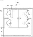
- FIG. 1 is a diagram illustrating a configuration of a general MMC.
- the MMC 10 is composed of, for example, three legs 13a, 13b, and 13c and six arms 11a, 11b, 11c, 12a, 12b, and 12c, and each arm includes multiple submodules (SMs). These arms are upper arms 11a, 11b, and 11c and lower arms 12a, 12b, and 12c.
- the figure illustrates four submodules (SMs) for each arm, but the number of submodules (SMs) may be changed.
- the MMC 10 converts a DC-side input voltage (Vdc) input via a bus into an AC-side output voltage through the three legs 13a, 13b, and 13c.
- the output voltage differs depending on on/off-state of the submodules (SMs) included in each arm. That is, when each of the upper and lower arms includes, for example, four submodules, the output voltage is adjusted at five levels (the number of submodules + 1) depending on the number of submodules (SMs) that remain in the on-state.
- on/off of a switch of the submodule (SM) of each arm may be controlled.
- FIG. 2 is a diagram illustrating an example of a configuration of a submodule of a general MMC.
- each submodule includes a so-called half-bridge circuit having a pair of power semiconductors 21 and a capacitor 22 connected in parallel to the power semiconductors 21.
- the power semiconductor 21 includes a power semiconductor element 21a and a diode 21b connected thereto in inverse-parallel.
- FIG. 3 is a diagram illustrating another example of a configuration of a submodule of a general MMC.
- each submodule includes a so-called full-bridge circuit having power semiconductors 31 in two pairs connected to each other in parallel and a capacitor 32 connected in parallel to the power semiconductors 31.
- the power semiconductor 31 includes a power semiconductor element 31a and a diode 31b connected thereto in inverse-parallel.
- an object of the present invention is to provide a MMC composed of multiple submodules with a suitable number of full-bridge circuits and half-bridge circuits so as to be capable of DC failure blocking and reducing loss.
- a modular multilevel converter including multiple converter arms, each converter arm having: N (N ⁇ 2, an integer) submodules connected to each other in series; and a circuit opening unit connected to the N submodules in series to open a circuit of the converter arm, wherein the N submodules are n (n ⁇ N) submodules including full-bridge circuits and N-n submodules including half-bridge circuits.
- the circuit opening unit may operate to open the circuit of the converter arm.
- the particular time (T) may be proportional to a number (n) of the submodules including the full-bridge circuits, and the number (n) of the submodules including the full-bridge circuits may be set in such a manner that the particular time (T) is longer than an operation time of the circuit opening unit.
- a number (n) of the submodules including the full-bridge circuits may be set in such a manner that a voltage stored in capacitors of the full-bridge circuits is less than a peak value of a three-phase line voltage at an AC side of the MMC.
- the circuit opening unit may include a disconnector that operates when the DC fault current in the converter arm is zero.
- the circuit opening unit may include one or more power semiconductors connected to each other in series, and the power semiconductors of the circuit opening unit may be placed in a reverse direction to the power semiconductors in the submodules.
- the power semiconductors of the circuit opening unit may be turned off, such that the DC fault current in the converter arm is blocked.
- the circuit opening unit may include: a disconnector that operates when the DC fault current in the converter arm is zero; and one or more power semiconductors connected to each other in series, the power semiconductors being connected to the disconnector in series, and the power semiconductors of the circuit opening unit may be placed in a reverse direction to the power semiconductors in the submodules, and may be turned off when the DC fault current in the converter arm is within a preset range from zero, such that the DC fault current in the converter arm is blocked.
- a DC failure blocking method for a modular multilevel converter including multiple converter arms, each converter arm having: N (N ⁇ 2, an integer) submodules connected to each other; and a circuit opening unit connected to the N submodules in series to open a circuit of the converter arm, wherein the N submodules are n (n ⁇ N) submodules having full-bridge circuits and N-n submodules having half-bridge circuits, the method including: recognizing, by a controller, DC failure of the MMC; turning off, by the controller, power semiconductors in the full-bridge circuits and the half-bridge circuits of the submodules; and operating, by the controller, the circuit opening unit to open the circuit of the converter arm and to block a DC fault current caused by the DC failure when the DC fault current in the converter arm is zero or within a preset range from zero.
- MMC modular multilevel converter
- the circuit opening unit may operate during a particular time (T) in which the DC fault current in the converter arm remains at zero or within the preset range from zero.
- the particular time (T) may be proportional to a number (n) of the submodules including the full-bridge circuits, and the number (n) of the submodules including the full-bridge circuits may be set in such a manner that the particular time (T) is longer than an operation time of the circuit opening unit.
- the circuit opening unit may include a disconnector that operates when the DC fault current in the converter arm is zero.
- the circuit opening unit may include one or more power semiconductors connected to each other in series and placed in a reverse direction to the power semiconductors in the submodules, and the power semiconductor of the circuit opening unit may be turned off when the DC fault current in the converter arm is within the preset range from zero, such that the DC fault current in the converter arm is blocked.
- the multiple submodules are a combination of full-bridge submodules and half-bridge submodules.
- the fault current is blocked, whereby internal elements of the submodules may be prevented from being damaged by the DC fault current.
- the voltage stored in the capacitor in the submodule of the MMC is prevented from discharging, and thus quick restarting is possible after removal of the DC failure.
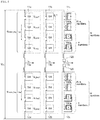
- FIG. 4 is a diagram illustrating a configuration of an MMC according to an embodiment of the present invention.
- the modular multilevel converter (MMC) 100 is composed of three legs 103a, 103b, and 103c, and six arms 101a, 101b, 101c, 102a, 102b, and 102c, and each arm includes multiple submodules (SMs). These arms are upper arms 101a, 101b, and 101c and lower arms 102a, 102b, and 102c. These converter arms 101a, 101b, 101c, 102a, 102b, and 102c have the same configuration, and thus in the present invention, for convenience of description, one converter arm 101a will be described.
- the converter arm 101a includes N (N ⁇ 2, an integer) submodules 110 connected to each other in series, and a circuit opening unit 120 connected to each submodule 110 in series to open a circuit of the converter arm 101a. Operation of these N submodules 110 and the circuit opening unit 120 is controlled by a controller (not shown).
- the N submodules 110 are composed of n (an integer with n ⁇ N) submodules 110a including full-bridge circuits and N-n submodules 110b including half-bridge circuits.
- the half-bridge circuit includes a pair of power semiconductors 111 connected to each other in series and a capacitor 112 connected in parallel to the power semiconductors 111.
- the full-bridge circuit includes power semiconductors 113 in two pairs connected to each other in parallel and a capacitor 114 connected in parallel to the power semiconductors 113.
- each of the power semiconductors 111 and 113 includes a power semiconductor element and a diode connected thereto in inverse-parallel.
- the power semiconductors 111 and 113 may be, for example, IGBTs, FETs, etc., and switching operation thereof is controlled by the controller (not shown).
- the fault current (hereinafter, referred to as a DC fault current) flows from the AC side to the DC side through the converter arm 101a of each phase. Therefore, when the DC failure occurs, the arm current flowing in the converter arm 101a is the DC fault current.
- the DC fault current is the high current that may damage internal elements of each submodule 110a.
- the circuit of the converter arm 101a is opened to block the DC fault current flowing into the converter arm 101a, whereby the converter circuit is protected.
- FIG. 5 is a waveform diagram illustrating an arm current in a converter arm when the DC failure of the MMC occurs according to the present invention.
- the controller (not shown) of the MMC 100 recognizes the DC failure at time t1 and the power semiconductors 111 and 113 of the submodules 110 are turned off, in reality the power semiconductors 111 and 113 require operation time for off-switching when the DC failure occurs suddenly at time t1 during normal operation. Therefore, during the short period of t1 - t2, the DC fault current rapidly increases.
- the controller turns off the power semiconductors 111 and 113 of the submodules 110 of the converter arm 101a, and thus the DC fault current gradually decreases.
- the DC fault current in the converter arm 101a gradually decreases and becomes zero when the voltage stored in the capacitors 114 of the n submodules 110a including the full-bridge circuits is lower than the peak value of the three-phase line voltage at the AC side (at time t3). Even if the number of submodules 110a including the full-bridge circuits is reduced, the period (t3 to t4) in which the DC fault current becomes zero is present.
- the length of the particular time (T) in which the DC fault current in the converter arm 101a becomes zero is proportional to the number (n) of submodules 110a including the full-bridge circuits.
- the number (n) of submodules 110a including the full-bridge circuits is preferably set in such a manner that the particular time (T) is longer than the operation time of the circuit opening unit 120. The reason therefor is that the circuit opening unit 120 operates when the DC fault current in the converter arm 101a is zero.
- the circuit opening unit 120 is operated such that the circuit of the converter arm 101a is opened, whereby the operation time of the circuit opening unit 120 is secured. Therefore, as described above, since the length of the particular time (T) (the period of t3 to t4) in which no DC fault current flows in the converter arm 101a is proportional to the number of submodules 110a including full-bridge circuits, in the present invention, it is important to determine the number (n) of submodules 110a including full-bridge circuits implemented in the converter arm 101a in such a manner that the length of the particular time (T) is longer than the operation time of the circuit opening unit 120.
- the circuit opening unit 120 is operated by the controller such that the circuit of the converter arm 101a is opened.
- the circuit opening of the converter arm 101a preferably includes disconnecting, isolating, or separating the lines that make up the converter arm 101a.
- the arm current flowing in the converter arm 101a or the DC fault current may be blocked from flowing, which may include blocking the arm current or the DC fault current by disconnecting, isolating, or separating the lines of the converter arm 101a.
- the MMC 100 compared to a conventional MMC which does not include the circuit opening unit 120, the MMC 100 provides a very important operation and effect, which will be described in detail.
- the fault current (Ix) indicated by the dotted line occurs after time t4 as shown in FIG. 5 and flows to the submodule of the MMC.
- the fault current (Ix) occurs when the charging voltage stored in the capacitor of the submodule including the full-bridge circuit is lower than the peak value of the three-phase line voltage at the AC side.
- the peak value of the fault current appears at a phase of 120 degrees such that the peak value of the three-phase line voltage is higher than the charging voltage of the submodule. Therefore, even if the number of submodules including full-bridge circuits is reduced, the fault current (Ix) is present as shown in stage 3 of FIG. 5 .
- the fault current (Ix) occurring in the conventional method is fundamentally blocked. That is, according to the present invention, the MMC 100 includes the circuit opening unit 120, and when the DC fault current in the converter arm 101a is zero, the circuit opening unit 120 is operated to open the circuit of the converter arm 101a. Thus, unlike the conventional case, the fault current (Ix) does not flow in the converter arm 101a, and the current remains at zero as indicated by the solid line (A) in FIG. 5 .
- the circuit opening unit 120 preferably includes, for example, a disconnector that disconnects the circuit when the DC fault current in the converter arm 101a is zero. It is desirable to use an ultra-fast disconnector with a short operation time to quickly disconnect the circuit when the DC fault current is zero.
- the disconnector is a switch that operates while no current flows in the circuit, and thus in the present invention, it is important to maintain the current at zero during the operation time of the disconnector by adjusting the number of submodules including full-bridge circuits.
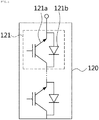
- FIG. 6 is a diagram illustrating an example of a configuration of a circuit opening unit according to another embodiment of the present invention.
- the circuit opening unit 120 includes one or more power semiconductors 121. It is important that the power semiconductors 121 are placed in the reverse direction to the power semiconductors 111 and 113 in the submodules 110 so as to block the DC fault current supplied from the AC side.
- the power semiconductor 121 includes a power semiconductor element 121a connected in inverse-series to the submodules 110 as described above and a diode 121b connected in inverse-parallel to the power semiconductor element 121a.
- the controller turns off the power semiconductors 111 and 113 of the full-bridge circuits and the half-bridge circuits of the submodules 110.
- the DC fault current in the converter arm 101a gradually decreases and becomes zero.
- the power semiconductor 121 of the circuit opening unit 120 is turned off by the controller such that the DC fault current is blocked.
- the power semiconductor 121 may be turned off. This is because the disconnector is a switch element operable when no current flows in the circuit, so the current of zero is required, but the power semiconductor switch may be turned off to block the current even though the low current flows rather than the current of zero.
- the circuit opening unit 120 may include the disconnector and one or more power semiconductors 121 connected to the disconnector in series.
- the circuit opening unit 120 is implemented by connecting the disconnector and the power semiconductor in series such that the performance of blocking the DC fault current may be enhanced.
- the MMC 100 includes the multiple converter arms as described above, and each converter arm includes N (N ⁇ 2, an integer) submodules 110 connected to each other in series and the circuit opening unit 120 connected to the N submodules in series to open the circuit of the converter arm.
- the N submodules 110 are n (n ⁇ N) submodules including full-bridge circuits and the remaining N-n submodules including half-bridge circuits.
- the controller (not shown) recognizes the DC failure at step S101, and the power semiconductors 111 and 113 of the full-bridge circuits and the half-bridge circuits configured in respective submodules 110 are turned off at step S103. Then, when the DC fault current in the converter arm is zero or within the preset range from zero, the controller operates the circuit opening unit 120 to open the circuit of the converter arm and to block the DC fault current caused by the DC failure at step S105.
- the circuit opening unit 120 operates during the particular time (T) in which the DC fault current in the converter arm remains at zero or within the preset range from zero.
- the particular time (T) is proportional to the number (n) of submodules including full-bridge circuits, and the number (n) of submodules including full-bridge circuits is set in such a manner that the particular time (T) is longer than the operation time of the circuit opening unit 120. This is because when the circuit opening unit 120 is implemented with the disconnector, the current flowing in the converter arm is required to remain at zero.
- the circuit opening unit 120 may be implemented with one or more power semiconductors 121 connected to each other in series, or as another example, with the disconnector and one or more power semiconductors 121 connected to each other in series.
- each converter arm of the MMC 100 is composed of the multiple submodules and the circuit opening unit, and the multiple submodules are a combination of submodules including half-bridge circuits and submodules including full-bridge circuits. Accordingly, when the DC failure occurs, the DC fault current flowing into the converter arm is blocked. Further, compared to the MMC composed of only submodules including full-bridge circuits, switching loss may be significantly reduced and the costs may be reduced. Also, the present invention partially applies submodules including full-bridge circuits to enable the current flowing in the converter arm to be zero, such that the circuit opening unit 120 may be implemented with the disconnector.
Landscapes
- Engineering & Computer Science (AREA)
- Power Engineering (AREA)
- Inverter Devices (AREA)
- Rectifiers (AREA)
Abstract
Description
- The present invention relates to a modular multilevel converter (MMC). More particularly, the present invention relates to a MMC and a DC failure blocking method therefor, the MMC and the method being capable of DC failure blocking and reducing loss using a combination of half-bridge submodules and full-bridge submodules for converter arms of the MMC.
- A modular multilevel converter (MMC) is a type of multilevel converter which is composed of multiple submodules (SMs). The modular multilevel converter (MMC) is capable of producing high voltage output and large capacity output that a multi-converter has, and of adjusting the output voltage with a stepped output.
- Such a MMC is simple in structure, compared to a general multilevel converter, and spare submodules may be used to extend life expectancy.
-
FIG. 1 is a diagram illustrating a configuration of a general MMC. - Referring to
FIG. 1 , the MMC 10 is composed of, for example, threelegs arms upper arms lower arms - The MMC 10 converts a DC-side input voltage (Vdc) input via a bus into an AC-side output voltage through the three
legs -
FIG. 2 is a diagram illustrating an example of a configuration of a submodule of a general MMC. - Referring to
FIG. 2 , each submodule (SM) includes a so-called half-bridge circuit having a pair ofpower semiconductors 21 and acapacitor 22 connected in parallel to thepower semiconductors 21. Thepower semiconductor 21 includes apower semiconductor element 21a and adiode 21b connected thereto in inverse-parallel. - However, in a conventional MMC, there are many countermeasures against AC failure, but there are few countermeasures against DC failure. That is, in the case of a conventional submodule composed of a half-bridge circuit, when the DC failure occurs, the fault current flows from the AC side only to the
diode 21b, and thus the fault current cannot be blocked. Thus, in order to block the fault current, a conventional submodule composed of a full-bridge circuit has been proposed. -
FIG. 3 is a diagram illustrating another example of a configuration of a submodule of a general MMC. - Referring to
FIG. 3 , each submodule (SM) includes a so-called full-bridge circuit havingpower semiconductors 31 in two pairs connected to each other in parallel and a capacitor 32 connected in parallel to thepower semiconductors 31. Thepower semiconductor 31 includes apower semiconductor element 31a and adiode 31b connected thereto in inverse-parallel. - As described above, in the case of the submodule composed of the full-bridge circuit, when DC failure occurs, the reverse voltage is applied to a capacitor 33 inside due to the fault current from the AC side such that the fault current is blocked. However, the loss caused by switching operation of an
IGBT 31 increases. In practice, when submodules with respect to the same number thereof are composed of full-bridge circuits, compared to half-bridge circuits, about 30 % or more of switching loss occurs. - Accordingly, the present invention has been made keeping in mind the above problems occurring in the related art, and an object of the present invention is to provide a MMC composed of multiple submodules with a suitable number of full-bridge circuits and half-bridge circuits so as to be capable of DC failure blocking and reducing loss.
- According to the present invention, there is provided a modular multilevel converter (MMC) including multiple converter arms, each converter arm having: N (N ≥ 2, an integer) submodules connected to each other in series; and a circuit opening unit connected to the N submodules in series to open a circuit of the converter arm, wherein the N submodules are n (n < N) submodules including full-bridge circuits and N-n submodules including half-bridge circuits.
- In the present invention, when DC failure of the MMC occurs, power semiconductors in the full-bridge circuits and the half-bridge circuits of the submodules may be turned off, and a DC fault current in the converter arm may be zero during the particular time (T).
- In the present invention, during the particular time (T), the circuit opening unit may operate to open the circuit of the converter arm.
- In the present invention, the particular time (T) may be proportional to a number (n) of the submodules including the full-bridge circuits, and the number (n) of the submodules including the full-bridge circuits may be set in such a manner that the particular time (T) is longer than an operation time of the circuit opening unit.
- In the present invention, a number (n) of the submodules including the full-bridge circuits may be set in such a manner that a voltage stored in capacitors of the full-bridge circuits is less than a peak value of a three-phase line voltage at an AC side of the MMC.
- In the present invention, the circuit opening unit may include a disconnector that operates when the DC fault current in the converter arm is zero.
- In the present invention, the circuit opening unit may include one or more power semiconductors connected to each other in series, and the power semiconductors of the circuit opening unit may be placed in a reverse direction to the power semiconductors in the submodules.
- In the present invention, when the DC fault current in the converter arm is within a preset range from zero, the power semiconductors of the circuit opening unit may be turned off, such that the DC fault current in the converter arm is blocked.
- In the present invention, the circuit opening unit may include: a disconnector that operates when the DC fault current in the converter arm is zero; and one or more power semiconductors connected to each other in series, the power semiconductors being connected to the disconnector in series, and the power semiconductors of the circuit opening unit may be placed in a reverse direction to the power semiconductors in the submodules, and may be turned off when the DC fault current in the converter arm is within a preset range from zero, such that the DC fault current in the converter arm is blocked.
- Also, according to the present invention, there is provided a DC failure blocking method for a modular multilevel converter (MMC) including multiple converter arms, each converter arm having: N (N ≥ 2, an integer) submodules connected to each other; and a circuit opening unit connected to the N submodules in series to open a circuit of the converter arm, wherein the N submodules are n (n < N) submodules having full-bridge circuits and N-n submodules having half-bridge circuits, the method including: recognizing, by a controller, DC failure of the MMC; turning off, by the controller, power semiconductors in the full-bridge circuits and the half-bridge circuits of the submodules; and operating, by the controller, the circuit opening unit to open the circuit of the converter arm and to block a DC fault current caused by the DC failure when the DC fault current in the converter arm is zero or within a preset range from zero.
- In the present invention, the circuit opening unit may operate during a particular time (T) in which the DC fault current in the converter arm remains at zero or within the preset range from zero.
- In the present invention, the particular time (T) may be proportional to a number (n) of the submodules including the full-bridge circuits, and the number (n) of the submodules including the full-bridge circuits may be set in such a manner that the particular time (T) is longer than an operation time of the circuit opening unit.
- In the present invention, the circuit opening unit may include a disconnector that operates when the DC fault current in the converter arm is zero.
- In the present invention, the circuit opening unit may include one or more power semiconductors connected to each other in series and placed in a reverse direction to the power semiconductors in the submodules, and the power semiconductor of the circuit opening unit may be turned off when the DC fault current in the converter arm is within the preset range from zero, such that the DC fault current in the converter arm is blocked.
- As described above, according to the present invention, in the MMC, the multiple submodules are a combination of full-bridge submodules and half-bridge submodules. Thus, when the DC failure of the MMC occurs, the fault current is blocked, whereby internal elements of the submodules may be prevented from being damaged by the DC fault current.
- Also, according to the present invention, compared to a conventional full-bridge submodule having the same effect, implementation costs are reduced by using fewer IGBTs and diodes. Furthermore, a switching operation does not occur at all times, and thus switching loss decreases.
- Also, according to the present invention, the voltage stored in the capacitor in the submodule of the MMC is prevented from discharging, and thus quick restarting is possible after removal of the DC failure.
-
-
FIG. 1 is a diagram illustrating a configuration of a general MMC. -
FIG. 2 is a diagram illustrating an example of a configuration of a submodule of a general MMC. -
FIG. 3 is a diagram illustrating another example of a configuration of a submodule of a general MMC. -
FIG. 4 is a diagram illustrating a configuration of an MMC according to an embodiment of the present invention. -
FIG. 5 is a waveform diagram illustrating a DC fault current in a converter arm when DC failure of an MMC occurs according to the present invention. -
FIG. 6 is a diagram illustrating an example of a configuration a circuit opening unit according to another embodiment of the present invention. - Hereinafter, embodiments of the present invention will be described in detail with reference to the illustrative drawings. It is noted that in assigning reference numerals to elements in the drawings, the same reference numerals designate the same elements throughout the drawings although the elements are shown in different drawings. Also, in describing embodiments of the present invention, the detailed descriptions of known related constitutions or functions thereof may be omitted if they make the gist of the present invention unclear.
- Further, when describing the elements of the present invention, terms such as first, second, A, B, (a), (b), etc. may be used. Since these terms are provided merely for the purpose of distinguishing the elements from each other, they do not limit the nature, sequence or order of the elements. When an element is "coupled to", "combined with", or "connected to" another element, it can be directly coupled to the other element or intervening elements may be present therebetween.
-
FIG. 4 is a diagram illustrating a configuration of an MMC according to an embodiment of the present invention. - Referring to
FIG. 4 , according to the present invention, the modular multilevel converter (MMC) 100 is composed of three legs 103a, 103b, and 103c, and six arms 101a, 101b, 101c, 102a, 102b, and 102c, and each arm includes multiple submodules (SMs). These arms are upper arms 101a, 101b, and 101c and lower arms 102a, 102b, and 102c. These converter arms 101a, 101b, 101c, 102a, 102b, and 102c have the same configuration, and thus in the present invention, for convenience of description, one converter arm 101a will be described. - The converter arm 101a includes N (N ≥ 2, an integer) submodules 110 connected to each other in series, and a
circuit opening unit 120 connected to each submodule 110 in series to open a circuit of the converter arm 101a. Operation of these N submodules 110 and thecircuit opening unit 120 is controlled by a controller (not shown). - Here, according to the embodiment, the N submodules 110 are composed of n (an integer with n < N) submodules 110a including full-bridge circuits and
N-n submodules 110b including half-bridge circuits. The half-bridge circuit includes a pair of power semiconductors 111 connected to each other in series and a capacitor 112 connected in parallel to the power semiconductors 111. The full-bridge circuit includes power semiconductors 113 in two pairs connected to each other in parallel and a capacitor 114 connected in parallel to the power semiconductors 113. Also, each of the power semiconductors 111 and 113 includes a power semiconductor element and a diode connected thereto in inverse-parallel. The power semiconductors 111 and 113 may be, for example, IGBTs, FETs, etc., and switching operation thereof is controlled by the controller (not shown). - In the case of the MMC 100 composed as described above, when failure such as a short circuit occurs at the DC side, the fault current (hereinafter, referred to as a DC fault current) flows from the AC side to the DC side through the converter arm 101a of each phase. Therefore, when the DC failure occurs, the arm current flowing in the converter arm 101a is the DC fault current. The DC fault current is the high current that may damage internal elements of each submodule 110a. In the present invention, when the DC failure of the MMC 100 occurs, the circuit of the converter arm 101a is opened to block the DC fault current flowing into the converter arm 101a, whereby the converter circuit is protected.
- Hereinafter, operation of the MMC 100 and a DC failure blocking method according to the present invention will be described in detail.
-
FIG. 5 is a waveform diagram illustrating an arm current in a converter arm when the DC failure of the MMC occurs according to the present invention. - Referring to
FIG. 5 , according to the present invention, when the MMC 100 is in a normal state, normal DC current (Is) steadily flows in the converter arm 101a. When the DC failure of the MMC 100 occurs at time t1, the voltage stored in the capacitors 112 and 114 of the full-bridge circuits and the half-bridge circuits of the submodules 110 is discharges and the free-wheeling current flows. Thus, the DC fault current in the converter arm 101a instantaneously increases rapidly until time t2. Here, although the controller (not shown) of the MMC 100 recognizes the DC failure at time t1 and the power semiconductors 111 and 113 of the submodules 110 are turned off, in reality the power semiconductors 111 and 113 require operation time for off-switching when the DC failure occurs suddenly at time t1 during normal operation. Therefore, during the short period of t1 - t2, the DC fault current rapidly increases. - Thereafter, from time t2, the controller turns off the power semiconductors 111 and 113 of the submodules 110 of the converter arm 101a, and thus the DC fault current gradually decreases. As described above, the DC fault current in the converter arm 101a gradually decreases and becomes zero when the voltage stored in the capacitors 114 of the n submodules 110a including the full-bridge circuits is lower than the peak value of the three-phase line voltage at the AC side (at time t3). Even if the number of submodules 110a including the full-bridge circuits is reduced, the period (t3 to t4) in which the DC fault current becomes zero is present. That is, when there is at least one
submodule 110a including the full-bridge circuit, at least a particular time (T) (the period of t3 to t4) in which the DC fault current becomes zero is present. Here, the length of the particular time (T) in which the DC fault current in the converter arm 101a becomes zero is proportional to the number (n) of submodules 110a including the full-bridge circuits. The number (n) of submodules 110a including the full-bridge circuits is preferably set in such a manner that the particular time (T) is longer than the operation time of thecircuit opening unit 120. The reason therefor is that thecircuit opening unit 120 operates when the DC fault current in the converter arm 101a is zero. That is, while no current flows in the converter arm 101a, thecircuit opening unit 120 is operated such that the circuit of the converter arm 101a is opened, whereby the operation time of thecircuit opening unit 120 is secured. Therefore, as described above, since the length of the particular time (T) (the period of t3 to t4) in which no DC fault current flows in the converter arm 101a is proportional to the number of submodules 110a including full-bridge circuits, in the present invention, it is important to determine the number (n) of submodules 110a including full-bridge circuits implemented in the converter arm 101a in such a manner that the length of the particular time (T) is longer than the operation time of thecircuit opening unit 120. - As described above, within the particular time (T) of the period of t3 to t4 in which the DC fault current in the converter arm 101a becomes zero, the
circuit opening unit 120 is operated by the controller such that the circuit of the converter arm 101a is opened. Here, the circuit opening of the converter arm 101a preferably includes disconnecting, isolating, or separating the lines that make up the converter arm 101a. Also, in another embodiment, the arm current flowing in the converter arm 101a or the DC fault current may be blocked from flowing, which may include blocking the arm current or the DC fault current by disconnecting, isolating, or separating the lines of the converter arm 101a. - Here, according to the present invention, compared to a conventional MMC which does not include the
circuit opening unit 120, the MMC 100 provides a very important operation and effect, which will be described in detail. In the case of the conventional MMC including only the submodule having the full-bridge circuit rather than the circuit opening unit, the fault current (Ix) indicated by the dotted line occurs after time t4 as shown inFIG. 5 and flows to the submodule of the MMC. The fault current (Ix) occurs when the charging voltage stored in the capacitor of the submodule including the full-bridge circuit is lower than the peak value of the three-phase line voltage at the AC side. When the three-phase AC fault current is supplied from an AC side system, the peak value of the fault current appears at a phase of 120 degrees such that the peak value of the three-phase line voltage is higher than the charging voltage of the submodule. Therefore, even if the number of submodules including full-bridge circuits is reduced, the fault current (Ix) is present as shown instage 3 ofFIG. 5 . - In contrast, according to the present invention, the fault current (Ix) occurring in the conventional method is fundamentally blocked. That is, according to the present invention, the MMC 100 includes the
circuit opening unit 120, and when the DC fault current in the converter arm 101a is zero, thecircuit opening unit 120 is operated to open the circuit of the converter arm 101a. Thus, unlike the conventional case, the fault current (Ix) does not flow in the converter arm 101a, and the current remains at zero as indicated by the solid line (A) inFIG. 5 . - According to the present invention, the
circuit opening unit 120 preferably includes, for example, a disconnector that disconnects the circuit when the DC fault current in the converter arm 101a is zero. It is desirable to use an ultra-fast disconnector with a short operation time to quickly disconnect the circuit when the DC fault current is zero. The disconnector is a switch that operates while no current flows in the circuit, and thus in the present invention, it is important to maintain the current at zero during the operation time of the disconnector by adjusting the number of submodules including full-bridge circuits. -
FIG. 6 is a diagram illustrating an example of a configuration of a circuit opening unit according to another embodiment of the present invention. - Referring to
FIG. 6 , according to another embodiment of the present invention, thecircuit opening unit 120 includes one ormore power semiconductors 121. It is important that thepower semiconductors 121 are placed in the reverse direction to the power semiconductors 111 and 113 in the submodules 110 so as to block the DC fault current supplied from the AC side. Thepower semiconductor 121 includes apower semiconductor element 121a connected in inverse-series to the submodules 110 as described above and adiode 121b connected in inverse-parallel to thepower semiconductor element 121a. When the DC failure of the MMC 110 occurs, the controller turns off the power semiconductors 111 and 113 of the full-bridge circuits and the half-bridge circuits of the submodules 110. Thus, the DC fault current in the converter arm 101a gradually decreases and becomes zero. Here, thepower semiconductor 121 of thecircuit opening unit 120 is turned off by the controller such that the DC fault current is blocked. Here, unlike an example in which thecircuit opening unit 120 is implemented with the disconnector, in the case where thecircuit opening unit 120 is implemented with thepower semiconductor 121, when the DC fault current is not zero but is within a preset range from zero, thepower semiconductor 121 may be turned off. This is because the disconnector is a switch element operable when no current flows in the circuit, so the current of zero is required, but the power semiconductor switch may be turned off to block the current even though the low current flows rather than the current of zero. - In the meantime, although not shown in the drawings, according to still another embodiment of the present invention, the
circuit opening unit 120 may include the disconnector and one ormore power semiconductors 121 connected to the disconnector in series. Thecircuit opening unit 120 is implemented by connecting the disconnector and the power semiconductor in series such that the performance of blocking the DC fault current may be enhanced. - Hereinafter, the DC failure blocking method according to the configuration of the MMC 100 will be described. First, according to the present invention, the MMC 100 includes the multiple converter arms as described above, and each converter arm includes N (N ≥ 2, an integer) submodules 110 connected to each other in series and the
circuit opening unit 120 connected to the N submodules in series to open the circuit of the converter arm. Here, the N submodules 110 are n (n < N) submodules including full-bridge circuits and the remaining N-n submodules including half-bridge circuits. - When the DC failure of the MMC 100 occurs, the controller (not shown) recognizes the DC failure at step S101, and the power semiconductors 111 and 113 of the full-bridge circuits and the half-bridge circuits configured in respective submodules 110 are turned off at step S103. Then, when the DC fault current in the converter arm is zero or within the preset range from zero, the controller operates the
circuit opening unit 120 to open the circuit of the converter arm and to block the DC fault current caused by the DC failure at step S105. Here, thecircuit opening unit 120 operates during the particular time (T) in which the DC fault current in the converter arm remains at zero or within the preset range from zero. Also, the particular time (T) is proportional to the number (n) of submodules including full-bridge circuits, and the number (n) of submodules including full-bridge circuits is set in such a manner that the particular time (T) is longer than the operation time of thecircuit opening unit 120. This is because when thecircuit opening unit 120 is implemented with the disconnector, the current flowing in the converter arm is required to remain at zero. Thecircuit opening unit 120 may be implemented with one ormore power semiconductors 121 connected to each other in series, or as another example, with the disconnector and one ormore power semiconductors 121 connected to each other in series. - As described above, according to the present invention, each converter arm of the MMC 100 is composed of the multiple submodules and the circuit opening unit, and the multiple submodules are a combination of submodules including half-bridge circuits and submodules including full-bridge circuits. Accordingly, when the DC failure occurs, the DC fault current flowing into the converter arm is blocked. Further, compared to the MMC composed of only submodules including full-bridge circuits, switching loss may be significantly reduced and the costs may be reduced. Also, the present invention partially applies submodules including full-bridge circuits to enable the current flowing in the converter arm to be zero, such that the
circuit opening unit 120 may be implemented with the disconnector. - In the above description, although a description has been made such that all components constituting embodiments of the present invention are combined into a single component or are operated with the components being combined with each other, the present invention is not limited to those embodiments. That is, within the scope of the present invention, one or more of all components may be selectively combined and operated. Further, it should be understood that terms such as "comprise", "include", or "have" are merely intended to indicate that the corresponding component is internally present, unless a description to the contrary is specifically pointed out in context, and are not intended to exclude the possibility that other components may be additionally included. Unless differently defined, all terms used here including technical or scientific terms have the same meanings as the terms generally understood by those skilled in the art to which the present invention pertains. The terms identical to those defined in generally used dictionaries should be interpreted as having meanings identical to contextual meanings of the related art, and are not interpreted as being ideal or excessively formal meanings unless they are definitely defined in the present invention.
- The above description is merely intended to exemplarily describe the technical spirit of the present invention, and those skilled in the art will appreciate that various changes and modifications are possible without departing from the essential features of the present invention. Therefore, the embodiments disclosed in the present invention are not intended to restrict the technical spirit of the present invention and are merely intended to describe the present invention, and the scope of the present invention is not limited by those embodiments. The protection scope of the present invention should be defined by the accompanying claims, and the technical spirit of all equivalents thereof should be construed as being included in the scope of the present invention.
Claims (14)
- A modular multilevel converter (MMC) comprising multiple converter arms, each converter arm including:N (N ≥ 2, an integer) submodules connected to each other in series; anda circuit opening unit connected to the N submodules in series to open a circuit of the converter arm,wherein the N submodules are n (n < N) submodules including full-bridge circuits and N-n submodules including half-bridge circuits.
- The modular multilevel converter of claim 1, wherein when DC failure of the MMC occurs, power semiconductors in the full-bridge circuits and the half-bridge circuits of the submodules are turned off, and a DC fault current in the converter arm is zero during the particular time (T).
- The modular multilevel converter of claim 2, wherein during the particular time (T), the circuit opening unit operates to open the circuit of the converter arm.
- The modular multilevel converter of claim 3, wherein the particular time (T) is proportional to a number (n) of the submodules including the full-bridge circuits, and the number (n) of the submodules including the full-bridge circuits is set in such a manner that the particular time (T) is longer than an operation time of the circuit opening unit.
- The modular multilevel converter of claim 3, wherein a number (n) of the submodules including the full-bridge circuits is set in such a manner that a voltage stored in capacitors of the full-bridge circuits is less than a peak value of a three-phase line voltage at an AC side of the MMC.
- The modular multilevel converter of any one of claims 1 to 4, wherein the circuit opening unit includes a disconnector that operates when the DC fault current in the converter arm is zero.
- The modular multilevel converter of any one of claims 1 to 4, wherein the circuit opening unit includes one or more power semiconductors connected to each other in series, and the power semiconductors of the circuit opening unit are placed in a reverse direction to the power semiconductors in the submodules.
- The modular multilevel converter of claim 7, wherein when the DC fault current in the converter arm is within a preset range from zero, the power semiconductors of the circuit opening unit are turned off, such that the DC fault current in the converter arm is blocked.
- The modular multilevel converter of any one of claims 1 to 4, wherein the circuit opening unit includes: a disconnector that operates when the DC fault current in the converter arm is zero; and one or more power semiconductors connected to each other in series, the power semiconductors being connected to the disconnector in series, and
the power semiconductors of the circuit opening unit are placed in a reverse direction to the power semiconductors in the submodules, and are turned off when the DC fault current in the converter arm is within a preset range from zero, such that the DC fault current in the converter arm is blocked. - A DC failure blocking method for a modular multilevel converter (MMC) including multiple converter arms, each converter arm having: N (N ≥ 2, an integer) submodules connected to each other; and a circuit opening unit connected to the N submodules in series to open a circuit of the converter arm, wherein the N submodules are n (n < N) submodules having full-bridge circuits and N-n submodules having half-bridge circuits, the method comprising:recognizing, by a controller, DC failure of the MMC;turning off, by the controller, power semiconductors in the full-bridge circuits and the half-bridge circuits of the submodules; andoperating, by the controller, the circuit opening unit to open the circuit of the converter arm and to block a DC fault current caused by the DC failure when the DC fault current in the converter arm is zero or within a preset range from zero.
- The method of claim 10, wherein the circuit opening unit operates during a particular time (T) in which the DC fault current in the converter arm remains at zero or within the preset range from zero.
- The method of claim 11, wherein the particular time (T) is proportional to a number (n) of the submodules including the full-bridge circuits, and the number (n) of the submodules including the full-bridge circuits is set in such a manner that the particular time (T) is longer than an operation time of the circuit opening unit.
- The method of claim 11, wherein the circuit opening unit includes a disconnector that operates when the DC fault current in the converter arm is zero.
- The method of claim 11, wherein the circuit opening unit includes one or more power semiconductors connected to each other in series and placed in a reverse direction to the power semiconductors in the submodules, and the power semiconductor of the circuit opening unit is turned off when the DC fault current in the converter arm is within the preset range from zero, such that the DC fault current in the converter arm is blocked.
Applications Claiming Priority (2)
| Application Number | Priority Date | Filing Date | Title |
|---|---|---|---|
| KR1020150190365A KR101857570B1 (en) | 2015-12-30 | 2015-12-30 | Modular multilevel converter and DC accident blocking method |
| PCT/KR2016/006720 WO2017115955A1 (en) | 2015-12-30 | 2016-06-23 | Modular multi-level converter and dc failure blocking method therefor |
Publications (3)
| Publication Number | Publication Date |
|---|---|
| EP3399615A1 true EP3399615A1 (en) | 2018-11-07 |
| EP3399615A4 EP3399615A4 (en) | 2019-09-04 |
| EP3399615B1 EP3399615B1 (en) | 2021-05-19 |
Family
ID=59225096
Family Applications (1)
| Application Number | Title | Priority Date | Filing Date |
|---|---|---|---|
| EP16881908.4A Active EP3399615B1 (en) | 2015-12-30 | 2016-06-23 | Modular multi-level converter and dc failure blocking method therefor |
Country Status (4)
| Country | Link |
|---|---|
| US (1) | US10998813B2 (en) |
| EP (1) | EP3399615B1 (en) |
| KR (1) | KR101857570B1 (en) |
| WO (1) | WO2017115955A1 (en) |
Cited By (2)
| Publication number | Priority date | Publication date | Assignee | Title |
|---|---|---|---|---|
| CN109830977A (en) * | 2019-04-08 | 2019-05-31 | 武汉大学 | The control method of direct current transportation circuit, DC transmission system and direct current transportation circuit |
| CN111864785A (en) * | 2020-08-14 | 2020-10-30 | 华中科技大学 | AC side cascaded hybrid MMC topology resistant to AC and DC faults and its control method |
Families Citing this family (35)
| Publication number | Priority date | Publication date | Assignee | Title |
|---|---|---|---|---|
| KR101923135B1 (en) * | 2016-12-26 | 2018-11-28 | 효성중공업 주식회사 | Modular multilevel converter system |
| EA202090027A1 (en) | 2017-06-12 | 2020-04-03 | Таэ Текнолоджиз, Инк. | MULTILEVEL MULTI QUADRANT HYSTERESIS CURRENT CONTROLLERS AND METHODS OF MANAGING THEM |
| CN110999065B (en) | 2017-06-16 | 2024-04-26 | 阿尔法能源技术公司 | Multi-level hysteresis voltage controller for voltage modulator and control method thereof |
| CN108336750B (en) * | 2018-03-08 | 2020-09-08 | 武汉大学 | Converter, three-pole DC system based on half-VSC and its failover control method |
| PE20201086A1 (en) | 2018-03-22 | 2020-10-22 | Tae Tech Inc | SYSTEMS AND METHODS FOR POWER MANAGEMENT AND CONTROL |
| CN108599606B (en) * | 2018-05-24 | 2019-10-15 | 浙江大学 | A control method for reducing the number of MMC bridge arm sub-modules |
| CN108847777B (en) * | 2018-07-16 | 2020-06-16 | 东北电力大学 | Isolated modular cascade converter based on high-frequency chain technology |
| EP3654510A1 (en) * | 2018-11-19 | 2020-05-20 | Maschinenfabrik Reinhausen GmbH | Pre-charging a modular multilevel converter |
| EP3654517B1 (en) * | 2018-11-19 | 2021-06-02 | Maschinenfabrik Reinhausen GmbH | Operating a modular multilevel converter |
| US11404973B2 (en) * | 2018-12-19 | 2022-08-02 | Di Shi | Generalized equivalent circuit model of MMC-HVDC for power system simulation |
| US12015354B2 (en) * | 2018-12-25 | 2024-06-18 | Mitsubishi Electric Corporation | Power conversion device capable of suppressing a harmonic component in an output voltage from an arm that increases after bypass of a failed converter cell |
| PH12021552423A1 (en) | 2019-03-29 | 2022-06-13 | Tae Tech Inc | Module-based energy systems having converter-source modules and methods related thereto |
| KR102184786B1 (en) | 2019-05-14 | 2020-11-30 | 연세대학교 산학협력단 | Modular Multilevel Converter Sub Module with DC Fault Current Breaking and Method for Controlling the same |
| CN113892223A (en) | 2019-05-30 | 2022-01-04 | 阿尔法能源技术公司 | Advanced battery charging at energy storage system modularization level |
| KR102359128B1 (en) | 2019-10-15 | 2022-02-07 | 목포대학교 산학협력단 | High Ratio DC-DC Converter Using Capacitor Drive |
| KR102324796B1 (en) | 2019-11-14 | 2021-11-11 | 목포대학교 산학협력단 | High efficiency High endurance DC/DC Converter for HVDC application |
| JP7374734B2 (en) * | 2019-11-26 | 2023-11-07 | 東芝インフラシステムズ株式会社 | power converter |
| KR20210099404A (en) | 2020-02-04 | 2021-08-12 | 효성중공업 주식회사 | HVDC system comprising a smoothing reactor control device and Control method thereof |
| EP3866325A1 (en) * | 2020-02-12 | 2021-08-18 | GE Energy Power Conversion Technology Ltd. | Method of short-circuiting a faulty converter submodule and power converter supporting same |
| CN111371116B (en) * | 2020-02-19 | 2021-12-14 | 东南大学 | Power electronic transformer based on hybrid modular multilevel converter |
| CN111224569B (en) * | 2020-02-20 | 2021-01-26 | 浙江大学 | A low full-bridge ratio sub-module hybrid MMC and its DC fault handling strategy |
| US12294291B2 (en) * | 2020-03-04 | 2025-05-06 | Mitsubishi Electric Corporation | Power conversion system |
| WO2021181583A1 (en) * | 2020-03-11 | 2021-09-16 | 三菱電機株式会社 | Power conversion device |
| JP7775216B2 (en) | 2020-04-14 | 2025-11-25 | ティーエーイー テクノロジーズ, インコーポレイテッド | Modular cascaded energy system with cooling and interchangeable energy source capabilities |
| WO2021211630A2 (en) | 2020-04-14 | 2021-10-21 | Tae Technologies, Inc. | Systems, devices, and methods for charging and discharging module-based cascaded energy systems |
| PE20230869A1 (en) | 2020-05-14 | 2023-05-31 | Tae Tech Inc | SYSTEMS, DEVICES AND METHODS FOR ELECTRIC VEHICLES BASED ON RAILS AND OTHERS WITH MODULAR CASCADE ENERGY SYSTEMS |
| CN112086984B (en) * | 2020-08-04 | 2022-09-23 | 中国长江三峡集团有限公司 | Control method of multifunctional MMC converter station |
| US20240359595A1 (en) * | 2020-08-24 | 2024-10-31 | Tae Technologies, Inc. | Modular Cascaded Energy Systems with a Cooling Apparatus and with Replaceable Energy Source Capability |
| US11923782B2 (en) | 2020-09-28 | 2024-03-05 | Tae Technologies, Inc. | Multi-phase module-based energy system frameworks and methods related thereto |
| CA3197315A1 (en) | 2020-09-30 | 2022-04-07 | Tae Technologies, Inc. | Systems, devices, and methods for intraphase and interphase balancing in module-based cascaded energy systems |
| US12139024B2 (en) | 2021-01-13 | 2024-11-12 | Tae Technologies, Inc. | Systems, devices, and methods for module-based cascaded energy systems |
| JP2024528571A (en) | 2021-07-07 | 2024-07-30 | ティーエーイー テクノロジーズ, インコーポレイテッド | Systems, devices, and methods for a modular-based cascaded energy system configured to interface with renewable energy sources - Patents.com |
| CN113872458B (en) * | 2021-09-23 | 2023-08-08 | 南京南瑞继保电气有限公司 | A light modular converter valve and its control method |
| CN114337335B (en) * | 2021-11-27 | 2023-11-24 | 深圳供电局有限公司 | Hybrid modular multi-level converter, control method and control device |
| CN120165581A (en) * | 2023-12-15 | 2025-06-17 | 宁德时代未来能源(上海)研究院有限公司 | Power module unit, energy storage valve module, energy storage valve and energy storage device |
Family Cites Families (21)
| Publication number | Priority date | Publication date | Assignee | Title |
|---|---|---|---|---|
| US20110080758A1 (en) * | 2008-06-10 | 2011-04-07 | Abb Technology Ag | Plant for transmitting electric power |
| WO2010025758A1 (en) * | 2008-09-05 | 2010-03-11 | Siemens Aktiengesellschaft | Device having a converter |
| DK2548277T3 (en) | 2010-03-15 | 2016-01-11 | Alstom Technology Ltd | Static reactive power compensator with flertrinskonverter |
| PL2671297T3 (en) * | 2011-02-01 | 2018-10-31 | Siemens Aktiengesellschaft | Method for clearing a fault on a hvdc line, arrangement for transmission of electrical current over a hvdc line and converter |
| WO2012116738A1 (en) * | 2011-03-01 | 2012-09-07 | Abb Research Ltd | Fault current limitation in dc power transmission systems |
| JP5941631B2 (en) * | 2011-07-26 | 2016-06-29 | 株式会社日立製作所 | Power converter |
| EP2815496A1 (en) * | 2012-02-16 | 2014-12-24 | ALSTOM Technology Ltd | Modular multilevel converter using asymmetry |
| CN102931863B (en) * | 2012-11-12 | 2015-04-15 | 华北电力大学 | Method for setting up modularized multi-level converter composite structure model |
| EP2946464B1 (en) * | 2013-01-21 | 2019-12-18 | ABB Schweiz AG | A multilevel converter with hybrid full-bridge cells |
| WO2015067322A1 (en) * | 2013-11-11 | 2015-05-14 | Green Power Technologies. S.L. | Modular voltage converter and method for mitigating the effects of a fault on a dc line |
| WO2015098146A1 (en) * | 2013-12-24 | 2015-07-02 | 三菱電機株式会社 | Power conversion device |
| KR101512188B1 (en) | 2014-02-11 | 2015-04-22 | 한국전기연구원 | A driving method of the modular multi-level converter and the apparatus thereof |
| JP5622978B1 (en) * | 2014-02-14 | 2014-11-12 | 三菱電機株式会社 | DC power transmission system protection system, AC / DC converter, and DC power transmission system disconnection method |
| WO2015124176A1 (en) | 2014-02-19 | 2015-08-27 | Abb Technology Ltd | Energy storage system comprising a modular multi-level converter |
| CN104009446B (en) * | 2014-02-27 | 2018-05-18 | 南京南瑞继保电气有限公司 | A kind of DC transmission protection device, transverter and guard method |
| US9871437B2 (en) * | 2014-07-10 | 2018-01-16 | University-Industry Foundation(UIF) | Fault current reduction structure of multi-level converter and apparatus using the fault current reduction structure |
| KR101558862B1 (en) * | 2014-10-31 | 2015-10-13 | 연세대학교 산학협력단 | Modular Multilevel converter and DC current accident reduction apparatus |
| US10256745B2 (en) * | 2014-07-22 | 2019-04-09 | Abb Schweiz Ag | Multilevel converter with reduced AC fault handling rating |
| JP5730456B1 (en) * | 2014-10-08 | 2015-06-10 | 三菱電機株式会社 | Power converter |
| CN107431444A (en) * | 2015-03-18 | 2017-12-01 | 通用电器技术有限公司 | The improvement of electrical component or the improvement relevant with electrical component |
| CN106329899B (en) * | 2015-07-01 | 2018-10-16 | 南京南瑞继保电气有限公司 | Fault current inhibits damper topological circuit and its control method and transverter |
-
2015
- 2015-12-30 KR KR1020150190365A patent/KR101857570B1/en active Active
-
2016
- 2016-06-23 US US16/067,543 patent/US10998813B2/en active Active
- 2016-06-23 WO PCT/KR2016/006720 patent/WO2017115955A1/en not_active Ceased
- 2016-06-23 EP EP16881908.4A patent/EP3399615B1/en active Active
Cited By (2)
| Publication number | Priority date | Publication date | Assignee | Title |
|---|---|---|---|---|
| CN109830977A (en) * | 2019-04-08 | 2019-05-31 | 武汉大学 | The control method of direct current transportation circuit, DC transmission system and direct current transportation circuit |
| CN111864785A (en) * | 2020-08-14 | 2020-10-30 | 华中科技大学 | AC side cascaded hybrid MMC topology resistant to AC and DC faults and its control method |
Also Published As
| Publication number | Publication date |
|---|---|
| EP3399615B1 (en) | 2021-05-19 |
| KR101857570B1 (en) | 2018-05-15 |
| US10998813B2 (en) | 2021-05-04 |
| US20190312504A1 (en) | 2019-10-10 |
| WO2017115955A1 (en) | 2017-07-06 |
| KR20170079613A (en) | 2017-07-10 |
| EP3399615A4 (en) | 2019-09-04 |
Similar Documents
| Publication | Publication Date | Title |
|---|---|---|
| EP3399615B1 (en) | Modular multi-level converter and dc failure blocking method therefor | |
| US10700587B2 (en) | Multilevel converter | |
| US9240731B2 (en) | Power cell bypass method and apparatus for multilevel inverter | |
| US11139733B2 (en) | Modular multilevel converter sub-module having DC fault current blocking function and method of controlling the same | |
| US9007787B2 (en) | Method and apparatus for bypassing Cascaded H-Bridge (CHB) power cells and power sub cell for multilevel inverter | |
| US9559541B2 (en) | Modular multilevel converter and charging circuit therefor | |
| US11108338B2 (en) | Dual submodule for a modular multilevel converter and modular multilevel converter including the same | |
| EP2471164B1 (en) | Converter cell module with autotransformer bypass, voltage source converter system comprising such a module and a method for controlling such a system | |
| US20160294276A1 (en) | Power conversion device | |
| US10224833B2 (en) | Drive signal modulation method of modular multilevel converter and fault isolation method | |
| JPWO2007129469A1 (en) | Power converter | |
| CN109792216B (en) | Power conversion device | |
| JP5095330B2 (en) | Inverter device | |
| KR20200096719A (en) | Three-level pulse width modulation technique for reducing semiconductor short circuit conduction loss | |
| US10673319B2 (en) | Modular multilevel converter system | |
| CN111164876B (en) | Multistage converter | |
| US7313008B2 (en) | Converter circuit for producing low harmonics | |
| Gierschner et al. | Fault-Tolerant Behaviour of the Three-Level Advanced-Active-Neutral-Point-Clamped Converter | |
| EP3399631B1 (en) | Redundancy control method of mmc for hvdc | |
| KR102419754B1 (en) | power converter | |
| CN118868651A (en) | Flying capacitor converter and method for protecting a flying capacitor converter | |
| EP4356506B1 (en) | Fault tolerant control of a solid state transformer | |
| Vejar et al. | A Low Passive Count Redundant Four-Level Inverter Topology | |
| SE1300553A1 (en) | DC / DC converter with multiple ports | |
| JP2004312902A (en) | Three-level power converter |
Legal Events
| Date | Code | Title | Description |
|---|---|---|---|
| STAA | Information on the status of an ep patent application or granted ep patent |
Free format text: STATUS: THE INTERNATIONAL PUBLICATION HAS BEEN MADE |
|
| PUAI | Public reference made under article 153(3) epc to a published international application that has entered the european phase |
Free format text: ORIGINAL CODE: 0009012 |
|
| STAA | Information on the status of an ep patent application or granted ep patent |
Free format text: STATUS: REQUEST FOR EXAMINATION WAS MADE |
|
| 17P | Request for examination filed |
Effective date: 20180705 |
|
| AK | Designated contracting states |
Kind code of ref document: A1 Designated state(s): AL AT BE BG CH CY CZ DE DK EE ES FI FR GB GR HR HU IE IS IT LI LT LU LV MC MK MT NL NO PL PT RO RS SE SI SK SM TR |
|
| AX | Request for extension of the european patent |
Extension state: BA ME |
|
| RAP1 | Party data changed (applicant data changed or rights of an application transferred) |
Owner name: KIM, HEE JIN Owner name: HUR, KYEON Owner name: HYOSUNG HEAVY INDUSTRIES CORPORATION |
|
| DAV | Request for validation of the european patent (deleted) | ||
| DAX | Request for extension of the european patent (deleted) | ||
| A4 | Supplementary search report drawn up and despatched |
Effective date: 20190805 |
|
| RIC1 | Information provided on ipc code assigned before grant |
Ipc: H02H 7/125 20060101AFI20190730BHEP Ipc: H02H 7/12 20060101ALI20190730BHEP Ipc: H02M 7/49 20070101ALI20190730BHEP Ipc: H02M 1/32 20070101ALI20190730BHEP |
|
| GRAP | Despatch of communication of intention to grant a patent |
Free format text: ORIGINAL CODE: EPIDOSNIGR1 |
|
| STAA | Information on the status of an ep patent application or granted ep patent |
Free format text: STATUS: GRANT OF PATENT IS INTENDED |
|
| RIC1 | Information provided on ipc code assigned before grant |
Ipc: H02M 7/483 20070101ALI20201106BHEP Ipc: H02M 1/32 20070101ALI20201106BHEP Ipc: H02H 7/12 20060101ALI20201106BHEP Ipc: H02H 7/125 20060101AFI20201106BHEP |
|
| INTG | Intention to grant announced |
Effective date: 20201127 |
|
| GRAS | Grant fee paid |
Free format text: ORIGINAL CODE: EPIDOSNIGR3 |
|
| GRAA | (expected) grant |
Free format text: ORIGINAL CODE: 0009210 |
|
| STAA | Information on the status of an ep patent application or granted ep patent |
Free format text: STATUS: THE PATENT HAS BEEN GRANTED |
|
| AK | Designated contracting states |
Kind code of ref document: B1 Designated state(s): AL AT BE BG CH CY CZ DE DK EE ES FI FR GB GR HR HU IE IS IT LI LT LU LV MC MK MT NL NO PL PT RO RS SE SI SK SM TR |
|
| REG | Reference to a national code |
Ref country code: GB Ref legal event code: FG4D |
|
| REG | Reference to a national code |
Ref country code: CH Ref legal event code: EP |
|
| REG | Reference to a national code |
Ref country code: DE Ref legal event code: R096 Ref document number: 602016058243 Country of ref document: DE |
|
| REG | Reference to a national code |
Ref country code: AT Ref legal event code: REF Ref document number: 1394920 Country of ref document: AT Kind code of ref document: T Effective date: 20210615 |
|
| REG | Reference to a national code |
Ref country code: IE Ref legal event code: FG4D |
|
| REG | Reference to a national code |
Ref country code: LT Ref legal event code: MG9D |
|
| REG | Reference to a national code |
Ref country code: AT Ref legal event code: MK05 Ref document number: 1394920 Country of ref document: AT Kind code of ref document: T Effective date: 20210519 |
|
| REG | Reference to a national code |
Ref country code: NL Ref legal event code: MP Effective date: 20210519 |
|
| PG25 | Lapsed in a contracting state [announced via postgrant information from national office to epo] |
Ref country code: HR Free format text: LAPSE BECAUSE OF FAILURE TO SUBMIT A TRANSLATION OF THE DESCRIPTION OR TO PAY THE FEE WITHIN THE PRESCRIBED TIME-LIMIT Effective date: 20210519 Ref country code: BG Free format text: LAPSE BECAUSE OF FAILURE TO SUBMIT A TRANSLATION OF THE DESCRIPTION OR TO PAY THE FEE WITHIN THE PRESCRIBED TIME-LIMIT Effective date: 20210819 Ref country code: AT Free format text: LAPSE BECAUSE OF FAILURE TO SUBMIT A TRANSLATION OF THE DESCRIPTION OR TO PAY THE FEE WITHIN THE PRESCRIBED TIME-LIMIT Effective date: 20210519 Ref country code: LT Free format text: LAPSE BECAUSE OF FAILURE TO SUBMIT A TRANSLATION OF THE DESCRIPTION OR TO PAY THE FEE WITHIN THE PRESCRIBED TIME-LIMIT Effective date: 20210519 Ref country code: FI Free format text: LAPSE BECAUSE OF FAILURE TO SUBMIT A TRANSLATION OF THE DESCRIPTION OR TO PAY THE FEE WITHIN THE PRESCRIBED TIME-LIMIT Effective date: 20210519 |
|
| PG25 | Lapsed in a contracting state [announced via postgrant information from national office to epo] |
Ref country code: LV Free format text: LAPSE BECAUSE OF FAILURE TO SUBMIT A TRANSLATION OF THE DESCRIPTION OR TO PAY THE FEE WITHIN THE PRESCRIBED TIME-LIMIT Effective date: 20210519 Ref country code: IS Free format text: LAPSE BECAUSE OF FAILURE TO SUBMIT A TRANSLATION OF THE DESCRIPTION OR TO PAY THE FEE WITHIN THE PRESCRIBED TIME-LIMIT Effective date: 20210919 Ref country code: GR Free format text: LAPSE BECAUSE OF FAILURE TO SUBMIT A TRANSLATION OF THE DESCRIPTION OR TO PAY THE FEE WITHIN THE PRESCRIBED TIME-LIMIT Effective date: 20210820 Ref country code: PT Free format text: LAPSE BECAUSE OF FAILURE TO SUBMIT A TRANSLATION OF THE DESCRIPTION OR TO PAY THE FEE WITHIN THE PRESCRIBED TIME-LIMIT Effective date: 20210920 Ref country code: NO Free format text: LAPSE BECAUSE OF FAILURE TO SUBMIT A TRANSLATION OF THE DESCRIPTION OR TO PAY THE FEE WITHIN THE PRESCRIBED TIME-LIMIT Effective date: 20210819 Ref country code: PL Free format text: LAPSE BECAUSE OF FAILURE TO SUBMIT A TRANSLATION OF THE DESCRIPTION OR TO PAY THE FEE WITHIN THE PRESCRIBED TIME-LIMIT Effective date: 20210519 Ref country code: RS Free format text: LAPSE BECAUSE OF FAILURE TO SUBMIT A TRANSLATION OF THE DESCRIPTION OR TO PAY THE FEE WITHIN THE PRESCRIBED TIME-LIMIT Effective date: 20210519 Ref country code: SE Free format text: LAPSE BECAUSE OF FAILURE TO SUBMIT A TRANSLATION OF THE DESCRIPTION OR TO PAY THE FEE WITHIN THE PRESCRIBED TIME-LIMIT Effective date: 20210519 |
|
| PG25 | Lapsed in a contracting state [announced via postgrant information from national office to epo] |
Ref country code: NL Free format text: LAPSE BECAUSE OF FAILURE TO SUBMIT A TRANSLATION OF THE DESCRIPTION OR TO PAY THE FEE WITHIN THE PRESCRIBED TIME-LIMIT Effective date: 20210519 |
|
| PG25 | Lapsed in a contracting state [announced via postgrant information from national office to epo] |
Ref country code: SM Free format text: LAPSE BECAUSE OF FAILURE TO SUBMIT A TRANSLATION OF THE DESCRIPTION OR TO PAY THE FEE WITHIN THE PRESCRIBED TIME-LIMIT Effective date: 20210519 Ref country code: SK Free format text: LAPSE BECAUSE OF FAILURE TO SUBMIT A TRANSLATION OF THE DESCRIPTION OR TO PAY THE FEE WITHIN THE PRESCRIBED TIME-LIMIT Effective date: 20210519 Ref country code: ES Free format text: LAPSE BECAUSE OF FAILURE TO SUBMIT A TRANSLATION OF THE DESCRIPTION OR TO PAY THE FEE WITHIN THE PRESCRIBED TIME-LIMIT Effective date: 20210519 Ref country code: RO Free format text: LAPSE BECAUSE OF FAILURE TO SUBMIT A TRANSLATION OF THE DESCRIPTION OR TO PAY THE FEE WITHIN THE PRESCRIBED TIME-LIMIT Effective date: 20210519 Ref country code: DK Free format text: LAPSE BECAUSE OF FAILURE TO SUBMIT A TRANSLATION OF THE DESCRIPTION OR TO PAY THE FEE WITHIN THE PRESCRIBED TIME-LIMIT Effective date: 20210519 Ref country code: CZ Free format text: LAPSE BECAUSE OF FAILURE TO SUBMIT A TRANSLATION OF THE DESCRIPTION OR TO PAY THE FEE WITHIN THE PRESCRIBED TIME-LIMIT Effective date: 20210519 Ref country code: EE Free format text: LAPSE BECAUSE OF FAILURE TO SUBMIT A TRANSLATION OF THE DESCRIPTION OR TO PAY THE FEE WITHIN THE PRESCRIBED TIME-LIMIT Effective date: 20210519 |
|
| REG | Reference to a national code |
Ref country code: CH Ref legal event code: PL |
|
| REG | Reference to a national code |
Ref country code: DE Ref legal event code: R097 Ref document number: 602016058243 Country of ref document: DE |
|
| REG | Reference to a national code |
Ref country code: BE Ref legal event code: MM Effective date: 20210630 |
|
| PLBE | No opposition filed within time limit |
Free format text: ORIGINAL CODE: 0009261 |
|
| STAA | Information on the status of an ep patent application or granted ep patent |
Free format text: STATUS: NO OPPOSITION FILED WITHIN TIME LIMIT |
|
| PG25 | Lapsed in a contracting state [announced via postgrant information from national office to epo] |
Ref country code: MC Free format text: LAPSE BECAUSE OF FAILURE TO SUBMIT A TRANSLATION OF THE DESCRIPTION OR TO PAY THE FEE WITHIN THE PRESCRIBED TIME-LIMIT Effective date: 20210519 Ref country code: LU Free format text: LAPSE BECAUSE OF NON-PAYMENT OF DUE FEES Effective date: 20210623 |
|
| 26N | No opposition filed |
Effective date: 20220222 |
|
| PG25 | Lapsed in a contracting state [announced via postgrant information from national office to epo] |
Ref country code: LI Free format text: LAPSE BECAUSE OF NON-PAYMENT OF DUE FEES Effective date: 20210630 Ref country code: IE Free format text: LAPSE BECAUSE OF NON-PAYMENT OF DUE FEES Effective date: 20210623 Ref country code: CH Free format text: LAPSE BECAUSE OF NON-PAYMENT OF DUE FEES Effective date: 20210630 |
|
| PG25 | Lapsed in a contracting state [announced via postgrant information from national office to epo] |
Ref country code: IS Free format text: LAPSE BECAUSE OF FAILURE TO SUBMIT A TRANSLATION OF THE DESCRIPTION OR TO PAY THE FEE WITHIN THE PRESCRIBED TIME-LIMIT Effective date: 20210919 Ref country code: FR Free format text: LAPSE BECAUSE OF NON-PAYMENT OF DUE FEES Effective date: 20210719 Ref country code: AL Free format text: LAPSE BECAUSE OF FAILURE TO SUBMIT A TRANSLATION OF THE DESCRIPTION OR TO PAY THE FEE WITHIN THE PRESCRIBED TIME-LIMIT Effective date: 20210519 |
|
| PG25 | Lapsed in a contracting state [announced via postgrant information from national office to epo] |
Ref country code: IT Free format text: LAPSE BECAUSE OF FAILURE TO SUBMIT A TRANSLATION OF THE DESCRIPTION OR TO PAY THE FEE WITHIN THE PRESCRIBED TIME-LIMIT Effective date: 20210519 Ref country code: BE Free format text: LAPSE BECAUSE OF NON-PAYMENT OF DUE FEES Effective date: 20210630 |
|
| PG25 | Lapsed in a contracting state [announced via postgrant information from national office to epo] |
Ref country code: CY Free format text: LAPSE BECAUSE OF FAILURE TO SUBMIT A TRANSLATION OF THE DESCRIPTION OR TO PAY THE FEE WITHIN THE PRESCRIBED TIME-LIMIT Effective date: 20210519 |
|
| PG25 | Lapsed in a contracting state [announced via postgrant information from national office to epo] |
Ref country code: HU Free format text: LAPSE BECAUSE OF FAILURE TO SUBMIT A TRANSLATION OF THE DESCRIPTION OR TO PAY THE FEE WITHIN THE PRESCRIBED TIME-LIMIT; INVALID AB INITIO Effective date: 20160623 |
|
| PG25 | Lapsed in a contracting state [announced via postgrant information from national office to epo] |
Ref country code: MK Free format text: LAPSE BECAUSE OF FAILURE TO SUBMIT A TRANSLATION OF THE DESCRIPTION OR TO PAY THE FEE WITHIN THE PRESCRIBED TIME-LIMIT Effective date: 20210519 |
|
| PG25 | Lapsed in a contracting state [announced via postgrant information from national office to epo] |
Ref country code: MT Free format text: LAPSE BECAUSE OF FAILURE TO SUBMIT A TRANSLATION OF THE DESCRIPTION OR TO PAY THE FEE WITHIN THE PRESCRIBED TIME-LIMIT Effective date: 20210519 |
|
| PGFP | Annual fee paid to national office [announced via postgrant information from national office to epo] |
Ref country code: DE Payment date: 20250106 Year of fee payment: 10 |
|
| PGFP | Annual fee paid to national office [announced via postgrant information from national office to epo] |
Ref country code: GB Payment date: 20250407 Year of fee payment: 10 |
|
| PG25 | Lapsed in a contracting state [announced via postgrant information from national office to epo] |
Ref country code: TR Free format text: LAPSE BECAUSE OF FAILURE TO SUBMIT A TRANSLATION OF THE DESCRIPTION OR TO PAY THE FEE WITHIN THE PRESCRIBED TIME-LIMIT Effective date: 20210519 |