EP3399598B1 - Connecteur electrique medical implantable possedant une conductivite constante - Google Patents
Connecteur electrique medical implantable possedant une conductivite constante Download PDFInfo
- Publication number
- EP3399598B1 EP3399598B1 EP18173726.3A EP18173726A EP3399598B1 EP 3399598 B1 EP3399598 B1 EP 3399598B1 EP 18173726 A EP18173726 A EP 18173726A EP 3399598 B1 EP3399598 B1 EP 3399598B1
- Authority
- EP
- European Patent Office
- Prior art keywords
- coil spring
- garter
- canted coil
- housing
- pin
- Prior art date
- Legal status (The legal status is an assumption and is not a legal conclusion. Google has not performed a legal analysis and makes no representation as to the accuracy of the status listed.)
- Expired - Lifetime
Links
- 239000000463 material Substances 0.000 claims description 12
- HWLDNSXPUQTBOD-UHFFFAOYSA-N platinum-iridium alloy Chemical compound [Ir].[Pt] HWLDNSXPUQTBOD-UHFFFAOYSA-N 0.000 claims description 10
- 238000003780 insertion Methods 0.000 claims description 7
- 230000037431 insertion Effects 0.000 claims description 7
- RTAQQCXQSZGOHL-UHFFFAOYSA-N Titanium Chemical compound [Ti] RTAQQCXQSZGOHL-UHFFFAOYSA-N 0.000 claims description 6
- 229910052719 titanium Inorganic materials 0.000 claims description 6
- 239000010936 titanium Substances 0.000 claims description 6
- 230000006835 compression Effects 0.000 claims description 3
- 238000007906 compression Methods 0.000 claims description 3
- 238000007790 scraping Methods 0.000 claims description 3
- 230000003247 decreasing effect Effects 0.000 claims description 2
- 230000000694 effects Effects 0.000 description 4
- 230000002829 reductive effect Effects 0.000 description 4
- 239000010935 stainless steel Substances 0.000 description 3
- 229910001220 stainless steel Inorganic materials 0.000 description 3
- 238000009434 installation Methods 0.000 description 2
- WABPQHHGFIMREM-UHFFFAOYSA-N lead(0) Chemical compound [Pb] WABPQHHGFIMREM-UHFFFAOYSA-N 0.000 description 2
- 230000014759 maintenance of location Effects 0.000 description 2
- 230000013011 mating Effects 0.000 description 2
- 230000000717 retained effect Effects 0.000 description 2
- 238000010276 construction Methods 0.000 description 1
- 239000007943 implant Substances 0.000 description 1
- 230000000670 limiting effect Effects 0.000 description 1
- 238000000034 method Methods 0.000 description 1
- 238000012986 modification Methods 0.000 description 1
- 230000004048 modification Effects 0.000 description 1
- 230000036961 partial effect Effects 0.000 description 1
- 230000003068 static effect Effects 0.000 description 1
Images

Classifications
-
- H—ELECTRICITY
- H01—ELECTRIC ELEMENTS
- H01R—ELECTRICALLY-CONDUCTIVE CONNECTIONS; STRUCTURAL ASSOCIATIONS OF A PLURALITY OF MUTUALLY-INSULATED ELECTRICAL CONNECTING ELEMENTS; COUPLING DEVICES; CURRENT COLLECTORS
- H01R13/00—Details of coupling devices of the kinds covered by groups H01R12/70 or H01R24/00 - H01R33/00
- H01R13/02—Contact members
- H01R13/03—Contact members characterised by the material, e.g. plating, or coating materials
-
- H—ELECTRICITY
- H01—ELECTRIC ELEMENTS
- H01R—ELECTRICALLY-CONDUCTIVE CONNECTIONS; STRUCTURAL ASSOCIATIONS OF A PLURALITY OF MUTUALLY-INSULATED ELECTRICAL CONNECTING ELEMENTS; COUPLING DEVICES; CURRENT COLLECTORS
- H01R13/00—Details of coupling devices of the kinds covered by groups H01R12/70 or H01R24/00 - H01R33/00
- H01R13/02—Contact members
- H01R13/15—Pins, blades or sockets having separate spring member for producing or increasing contact pressure
- H01R13/187—Pins, blades or sockets having separate spring member for producing or increasing contact pressure with spring member in the socket
-
- A—HUMAN NECESSITIES
- A61—MEDICAL OR VETERINARY SCIENCE; HYGIENE
- A61M—DEVICES FOR INTRODUCING MEDIA INTO, OR ONTO, THE BODY; DEVICES FOR TRANSDUCING BODY MEDIA OR FOR TAKING MEDIA FROM THE BODY; DEVICES FOR PRODUCING OR ENDING SLEEP OR STUPOR
- A61M5/00—Devices for bringing media into the body in a subcutaneous, intra-vascular or intramuscular way; Accessories therefor, e.g. filling or cleaning devices, arm-rests
-
- H—ELECTRICITY
- H01—ELECTRIC ELEMENTS
- H01R—ELECTRICALLY-CONDUCTIVE CONNECTIONS; STRUCTURAL ASSOCIATIONS OF A PLURALITY OF MUTUALLY-INSULATED ELECTRICAL CONNECTING ELEMENTS; COUPLING DEVICES; CURRENT COLLECTORS
- H01R13/00—Details of coupling devices of the kinds covered by groups H01R12/70 or H01R24/00 - H01R33/00
- H01R13/02—Contact members
- H01R13/10—Sockets for co-operation with pins or blades
- H01R13/11—Resilient sockets
- H01R13/111—Resilient sockets co-operating with pins having a circular transverse section
-
- H—ELECTRICITY
- H01—ELECTRIC ELEMENTS
- H01R—ELECTRICALLY-CONDUCTIVE CONNECTIONS; STRUCTURAL ASSOCIATIONS OF A PLURALITY OF MUTUALLY-INSULATED ELECTRICAL CONNECTING ELEMENTS; COUPLING DEVICES; CURRENT COLLECTORS
- H01R13/00—Details of coupling devices of the kinds covered by groups H01R12/70 or H01R24/00 - H01R33/00
- H01R13/62—Means for facilitating engagement or disengagement of coupling parts or for holding them in engagement
- H01R13/623—Casing or ring with helicoidal groove
-
- H—ELECTRICITY
- H01—ELECTRIC ELEMENTS
- H01R—ELECTRICALLY-CONDUCTIVE CONNECTIONS; STRUCTURAL ASSOCIATIONS OF A PLURALITY OF MUTUALLY-INSULATED ELECTRICAL CONNECTING ELEMENTS; COUPLING DEVICES; CURRENT COLLECTORS
- H01R2201/00—Connectors or connections adapted for particular applications
- H01R2201/12—Connectors or connections adapted for particular applications for medicine and surgery
Definitions
- the present invention is directed to medically implantable electrical connectors and is more particularly directed to medical connectors which have tailored connect and disconnect forces.
- Such connectors can be used in a number of medical devices such as, for example, pace makers defibrillators, and neuro-stimulators.
- Medically implantable electrical connectors are adherently different than a vast majority of other electrical connections due to the environment and critical nature of their use.
- Such medical connectors must not only be made of materials suitable for implanting within a body, but also must provide positive and unvarying conductivity thereacross in order to insure reliability of a functioning medical device.
- implantable electrical connectors have utilized a lead wire, or pin, and a housing with the lead wire removably fixed to the housing by a set screw. It should be appreciated that such set screws are small, thus losable. In addition, a set screw is very torque sensitive and requires a tool for Installation.
- the present invention provides for an implantable electrical connector with reduced resistivity and reduced resistivity variability under static and dynamic loading without the necessity of an installation tool.
- U.S. Patent No. 4,934,366 is directed to a feedthrough connector for an implantable medical device. Connections between a lead and a barrel assembly to carry electrical signals between the heart and the implantable device is improved by utilizing canted coil springs to make contact with the lead to enable repeated or multiple contacts.
- a medically implantable electrical connector in accordance with the present invention generally includes a housing having a bore with an internal groove therein along with a garter spring disposed in a groove.
- a pin is sized for insertion into the housing bore and may include an external groove for capturing the spring in order to removably latch the pin within a housing bore.
- Reduced resistivity across the connector including the housing spring and pin is achieved through the use of a flat bottom groove and by forming the housing, spring and pin from a combination of medically implantable materials in order to control the resistivity.
- the spring is formed from platinum iridium.
- one of the housing pin, or spring is preferable formed from platinum iridium with the most preferred being a platinum iridium spring.
- the remaining components, namely the housing and pin may be formed from MP35N or titanium grade-5 or stainless steel.
- inventions include a connector with a housing flat groove and an axial spring.
- the axial spring provides for greater conductivity with a housing with flat grooves in view of the fact that the axial spring motion produces a scraping action that removes oxides thus decreasing resistivity.
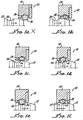
- connectors In general, two types of connectors will be hereinafter described.
- One type is for latching as shown in Figures 1a-1f in which the connector 10 includes a pin 12 retained in a housing 14 by a spring 16.
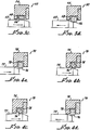
- FIGS. 2a-2d , 3a-3d and 4a-4d Shown in Figures 2a-2d , 3a-3d and 4a-4d are connectors 30, 50, 70 for holding pins 32, 52, 72 within respective housings 34, 54, 74 by the friction force derived by compressing a canted coil spring 36, 56, 76.
- the springs 16, 36, 56, 76 may be radial canted coil springs 16, 36, 56, with a housing V-groove 18, 38, or axial canted coil springs 76 with a flat bottom-housing groove 78. It has been found that axial springs are preferable for a flat bottom housing groove 78 inasmuch as there is a greater coil density, i.e. more coils per arcuate distance, disposed against the pin and a scraping motion of the axial spring 76 removes oxides.
- the springs 16, 36, 56, 76 may be inserted clockwise or counterclockwise with a back angle an the inside or the outside.
- Suitable springs are taught in U.S. Patent Nos. 5,108,076 , Figures 1-6 , U.S. Patent 4,893,795 , Figures 4 , 5a, 5b, 5c, 5d, 5e, 6a, and 6b and U.S. 5,139,243 , Figures 1a, 1b , 2a, and 2b to Balsells. All of these patents are teaching suitable spring designs for the present invention.
- the springs 16, 36, 56, 76 are generally made with an outside diameter slightly larger than the housing groove I.D.s so that upon assembling the spring 16, 36, 56, 76 into the grooves 18, 38, 58 and 78 it creates interference with the outside diameter of the spring and the inside diameter of the housing groove 18, 38, 58, 78.
- the interference provides a radial compression load that retains the spring 16, 36, 56 in the housing 14, 34, 54.
- the springs 16, 36, 56, 76 may be inserted clockwise or counter clockwise.
- the interference provides an axial compression load that retains the spring 76 within the housing 74. In this manner, the springs 16, 36, 56, 76, are firmly retained in place. It also insures conductivity between the outside diameter of the spring 16, 36, 56, 76 and the housing 14, 34, 54, 74.
- resistivity is a very important factor since the greater the resistivity the more electrical energy is dissipated as heat across the connector 10, 30, 50, 70, which is drawn from a battery (not shown), thus, limiting the life of the battery.
- the area of contact between the springs 16, 36 coils and the housing 14, 34 also effects the resistivity. The greater the area of contact of the springs 16, 36 with the housing 14, 34, the lower the resistivity.
- Connector 10 provides for latching. That is, the pin groove 20, when aligned with the housing groove 18 with the spring 16 therebetween, provides latching action as well as conductivity. At the same time such V-grooves 18 in the housing 14 assures consistent retention and resistivity.
- V-groove 18 effects the position, constraint of the spring and reduces the variability of resistivity.
- the V-groove 18 of the housing 14 may have various angles less than 180° to an included angle of about 135° or 90°, among others as shown in Figures 1a-1f and 2a-2d. It has been found that a 45° (90° included angle) constrains the coils, allows good retention in the coils and provides reduced resistivity.
- the increase in force will reduce resistivity and increase the constraint of the spring 16, 36, 56, 76 minimizing the variability of resistivity, especially under dynamic loads.
- the force may be varied by various manners, such as, for example, the back or front angle of the coils, wire diameter, ratio of coil height to wire diameter among others. All these parameters are discussed in the hereinabove referenced U.S. Patents.
- the ratio of disconnect to connect force can be controlled within a ratio of about 1 to 1 to about 10 to 1. With high disconnect to connect force ratio contact, and thus conductivity, is maintained. A number of condition for providing force ratios:
- Axial spring is compressed at assembly along the minor axis of the coil and in doing so increases the force acting on the walls of such groove and the more the squeeze between the coil height and the groove width the higher the radial force that is generated. This affects the radial force required to pass the pin through the housing contacting the spring. Such added force has an effect on the conductivity and resistivity that is not linear.
- the referenced patents also discuss the relationship between the angles of the pin, angles on the housing and shape of the coil, be it round or elliptical, such that it maximizes the area of contact between group services and the spring coils.
- connection 10, 30, 50, 70 provides a method for substantially effecting the resistivity of the connectors 10, 30, 50, 70.
- Materials for medical applications must be of the type that are stable in implant applications, such as, for example, stainless steel type 316L, MP35N, platinum-iridium, titanium and others.
- Table 1 shows condensed data on resistivity of different types of groove springs and materials all made with a common dimensions. TABLE 1 CONDENSED DATA ON RESISTIVITY OF DIFFERENT TYPES OF GROOVES, SPRINGS AND MATERIAL Item Material Flat Bottom-RADIAL V-Bottom RADIAL % Variation Between Flat Bottom Radial and V-Bottom Radial Flat Bottom AXIAL %Variation Between Flat Bottom Radial and Flat Bottom Axial No.
- S.S. is a stainless steel type 316L
- PT-IR is platinum-iridium
- MPN is MP35N
- TNM-5 titanium grade-5.
Claims (12)
- Connecteur électrique médical implantable (50, 70) comprenant :un logement (54, 74) qui comporte un alésage avec une gorge de fond plane (58, 78) en son sein ;un ressort à enroulement incliné en anneau cylindrique axial (76) ou un ressort à enroulement incliné en anneau cylindrique radial (56) qui est disposé dans ladite gorge de fond plane (58, 78) ; etune clavette (52, 72) qui est dimensionnée et disposée dans l'alésage du logement (54, 74) ;ledit logement (54, 74), ledit ressort à enroulement incliné en anneau cylindrique axial (76) ou ledit ressort à enroulement incliné en anneau cylindrique radial (56) et ladite clavette (52, 72) étant formés à partir d'une combinaison de matériaux médicaux implantables;caractérisé en ce qu'un élément constitutif pris parmi ledit logement (54, 74), ledit ressort à enroulement incliné en anneau cylindrique axial (76) ou ledit ressort à enroulement incliné en anneau cylindrique radial (56) et ladite clavette (52, 72) est formé à partir de platine iridium afin de contrôler la résistivité électrique entre ledit logement (54, 74), ledit ressort à enroulement incliné en anneau cylindrique axial (76) ou ledit ressort à enroulement incliné en anneau cylindrique radial (56) et ladite clavette (52, 72).
- Connecteur (50, 70) selon la revendication 1, dans lequel un diamètre externe dudit ressort à enroulement incliné en anneau cylindrique axial (76) ou dudit ressort à enroulement incliné en anneau cylindrique radial (56) est plus grand qu'un diamètre interne de la gorge de fond plane (58, 78) afin de créer une interférence qui assure une charge de compression qui retient ledit ressort à enroulement incliné en anneau cylindrique axial (76) ou ledit ressort à enroulement incliné en anneau cylindrique radial (56) en place à l'intérieur de la gorge de fond plane (58, 78).
- Connecteur (50, 70) selon la revendication 2, dans lequel l'interférence assure la conductivité entre le diamètre externe dudit ressort à enroulement incliné en anneau cylindrique axial (76) ou dudit ressort à enroulement incliné en anneau cylindrique radial (56) et le logement (54, 74).
- Connecteur (50, 70) selon l'une quelconque des revendications 1 à 3, dans lequel le ressort à enroulement incliné en anneau cylindrique axial (76) est comprimé le long d'un axe secondaire lors de l'assemblage.
- Connecteur (50, 70) selon la revendication 4, dans lequel ledit logement (54, 74) et ladite clavette (52, 72) sont formés à partir de MP35N.
- Connecteur (50, 70) selon la revendication 4, dans lequel ledit logement (54, 74) et ladite clavette (52, 72) sont formés à partir de titane grade 5.
- Connecteur (50, 70) selon l'une quelconque des revendications 1 à 3, dans lequel ledit logement (54, 74) et ladite clavette (52, 72) sont formés à partir de titane grade 5.
- Connecteur (50, 70) selon la revendication 1, dans lequel ladite clavette (52, 72) est disposée à l'intérieur de l'alésage du logement (54, 74) en appliquant une force de connexion afin d'insérer la clavette (52, 72) à l'intérieur de l'alésage du logement (54, 74), la clavette (52, 72) pouvant être enlevée hors du logement (54, 74) lorsqu'une force de déconnexion est appliquée.
- Connecteur (50, 70) selon la revendication 8, dans lequel un rapport de la force de déconnexion sur la force de connexion est entre 1 sur 1 et 10 sur 1 en sélectionnant ledit ressort à enroulement incliné en anneau cylindrique axial (76) ou ledit ressort à enroulement incliné en anneau cylindrique radial (56) qui présente un angle avant et en mettant en contact l'angle avant en premier lieu avec la clavette (52, 72) lors de l'insertion, en alignant une ligne centrale dudit ressort à enroulement incliné en anneau cylindrique axial (76) ou dudit ressort à enroulement incliné en anneau cylindrique radial (56) suivant un axe principal pour la rapprocher du point de charge de la clavette, en sélectionnant un rapport de la hauteur d'enroulement sur le diamètre de fil dudit ressort à enroulement incliné en anneau cylindrique axial (76) ou dudit ressort à enroulement incliné en anneau cylindrique radial (56), ou en sélectionnant un rapport de la largeur d'enroulement sur la hauteur d'enroulement.
- Connecteur (50, 70) selon la revendication 1, dans lequel le ressort à enroulement incliné en anneau cylindrique axial (76) réalise une action de grattage qui enlève les oxydes, ce qui diminue par voie de conséquence la résistivité.
- Connecteur (50, 70) selon la revendication 10, dans lequel la gorge de fond plane est localisée entre deux parois latérales et dans lequel le ressort à enroulement incliné en anneau cylindrique axial (76) entre en contact avec les deux parois latérales.
- Connecteur (50, 70) selon la revendication 1, dans lequel le ressort à enroulement incliné en anneau cylindrique axial (76) est réalisé à partir de platine iridium.
Applications Claiming Priority (3)
| Application Number | Priority Date | Filing Date | Title |
|---|---|---|---|
| US35736002P | 2002-02-15 | 2002-02-15 | |
| EP03713510.0A EP1476922B1 (fr) | 2002-02-15 | 2003-02-14 | Connecteur electrique medical implantable possedant une conductivite constante |
| PCT/US2003/004788 WO2003071635A1 (fr) | 2002-02-15 | 2003-02-14 | Connecteur electrique medical implantable possedant une conductivite constante |
Related Parent Applications (2)
| Application Number | Title | Priority Date | Filing Date |
|---|---|---|---|
| EP03713510.0A Division EP1476922B1 (fr) | 2002-02-15 | 2003-02-14 | Connecteur electrique medical implantable possedant une conductivite constante |
| EP03713510.0A Division-Into EP1476922B1 (fr) | 2002-02-15 | 2003-02-14 | Connecteur electrique medical implantable possedant une conductivite constante |
Publications (2)
| Publication Number | Publication Date |
|---|---|
| EP3399598A1 EP3399598A1 (fr) | 2018-11-07 |
| EP3399598B1 true EP3399598B1 (fr) | 2021-04-28 |
Family
ID=27757604
Family Applications (2)
| Application Number | Title | Priority Date | Filing Date |
|---|---|---|---|
| EP03713510.0A Expired - Lifetime EP1476922B1 (fr) | 2002-02-15 | 2003-02-14 | Connecteur electrique medical implantable possedant une conductivite constante |
| EP18173726.3A Expired - Lifetime EP3399598B1 (fr) | 2002-02-15 | 2003-02-14 | Connecteur electrique medical implantable possedant une conductivite constante |
Family Applications Before (1)
| Application Number | Title | Priority Date | Filing Date |
|---|---|---|---|
| EP03713510.0A Expired - Lifetime EP1476922B1 (fr) | 2002-02-15 | 2003-02-14 | Connecteur electrique medical implantable possedant une conductivite constante |
Country Status (5)
| Country | Link |
|---|---|
| US (1) | US6835084B2 (fr) |
| EP (2) | EP1476922B1 (fr) |
| JP (1) | JP2005518648A (fr) |
| AU (1) | AU2003217558A1 (fr) |
| WO (1) | WO2003071635A1 (fr) |
Families Citing this family (68)
| Publication number | Priority date | Publication date | Assignee | Title |
|---|---|---|---|---|
| US9267526B2 (en) | 2003-06-04 | 2016-02-23 | Bal Seal Engineering, Inc. | Spring latching connectors |
| US7210398B2 (en) * | 2004-02-18 | 2007-05-01 | Bal Seal Engineering Co., Inc. | Cover seals with latching locking features |
| US7274964B2 (en) * | 2004-04-16 | 2007-09-25 | Bal Seal Engineering Co., Inc. | Use of an axial canted coil spring as an electrical contact to minimize resistivity variations under dynamic loads |
| US20090039728A1 (en) * | 2004-04-29 | 2009-02-12 | Balsells Peter J | Contact assembly |
| US8657299B2 (en) * | 2004-07-15 | 2014-02-25 | John E. Rode | Mounting rings for shafts |
| US20060228166A1 (en) * | 2005-04-05 | 2006-10-12 | Bal Seal Engineering Co., Inc. | Ball holding, latching and locking applications using radial and axial springs |
| US7294020B2 (en) * | 2005-05-25 | 2007-11-13 | Alcoa Fujikura Ltd. | Canted coil spring power terminal and sequence connection system |
| US7229327B2 (en) * | 2005-05-25 | 2007-06-12 | Alcoa Fujikura Limited | Canted coil spring power terminal and sequence connection system |
| US7502217B2 (en) * | 2007-02-16 | 2009-03-10 | Medtronic, Inc. | Filtering capacitor feedthrough assembly |
| US7914351B2 (en) * | 2007-04-13 | 2011-03-29 | Bal Seal Engineering | Electrical connectors with improved electrical contact performance |
| WO2009076310A2 (fr) | 2007-12-06 | 2009-06-18 | Bal Seal Engineering | Connecteur en ligne |
| EP2235421A4 (fr) * | 2007-12-21 | 2016-08-17 | Bal Seal Eng | Mécanisme de verrouillage avec moyen de démontage rapide |
| CN101682137B (zh) * | 2008-04-14 | 2012-07-18 | 三菱电机株式会社 | 触点 |
| US9293849B2 (en) * | 2008-07-30 | 2016-03-22 | Bal Seal Engineering, Inc. | Electrical connector using a canted coil multi-metallic wire |
| US7883094B2 (en) * | 2008-08-19 | 2011-02-08 | Delaware Capital Formation, Inc. | Offset stacked sealing system |
| FR2935202B1 (fr) * | 2008-08-21 | 2010-10-22 | Labinal | Dispositif de connexion entre un cable electrique et une structure conductrice, notamment pour circuit de retour de courant |
| WO2010030897A2 (fr) | 2008-09-15 | 2010-03-18 | Bal Seal Engineering | Appareil comprenant un raccord à broche pour fixer un premier élément et un second élément l’un à l’autre, et procédés associés |
| WO2010046242A2 (fr) * | 2008-10-21 | 2010-04-29 | Delphi Technologies, Inc. | Connecteur coaxial et récipient |
| US8167640B2 (en) * | 2009-03-19 | 2012-05-01 | Bioness Inc. | Flexible connector for implantable electrical stimulation lead |
| US20100289198A1 (en) * | 2009-04-28 | 2010-11-18 | Pete Balsells | Multilayered canted coil springs and associated methods |
| CA2708877C (fr) * | 2009-07-07 | 2017-10-10 | National Oilwell Varco, L.P. | Dispositif de retenue pour manchon d'etancheite de joint de cardan d'arbre d'entrainement pour moteur de fond de trou |
| US8684362B2 (en) | 2009-08-12 | 2014-04-01 | Bal Seal Engineering, Inc. | Cartridge seal assemblies and associated methods |
| US8590867B2 (en) * | 2009-09-15 | 2013-11-26 | Bal Seal Engineering, Inc. | Variable canted coil spring cross section |
| CN101763957B (zh) | 2009-12-18 | 2013-11-27 | 张正周 | 一种导电用弹簧触指 |
| US8382532B2 (en) * | 2010-05-13 | 2013-02-26 | Bal Seal Engineering, Inc. | Insert element engaging a canted coil spring disposed in a groove in a bore formed by two housing parts |
| US8491346B2 (en) * | 2010-05-13 | 2013-07-23 | Bal Seal Engineering, Inc. | Electrical contacts using canted coil springs and stamped housings and methods thereof |
| US8342893B2 (en) | 2010-07-02 | 2013-01-01 | Lear Corporation | Stamped electrical terminal |
| US8282429B2 (en) | 2010-07-02 | 2012-10-09 | Lear Corporation | Electrical terminal with coil spring |
| US8869373B2 (en) | 2010-07-02 | 2014-10-28 | Lear Corporation | Arbor insertion tool |
| US8382533B2 (en) | 2010-07-02 | 2013-02-26 | Lear Corporation | Electrically conducting terminal |
| JP5444542B2 (ja) * | 2010-08-26 | 2014-03-19 | 株式会社富永製作所 | 給油装置の緊急遮断装置 |
| US9004805B2 (en) | 2010-11-30 | 2015-04-14 | Bal Seal Engineering, Inc. | Multi-stage engagement assemblies and related methods |
| US8844126B2 (en) | 2010-12-23 | 2014-09-30 | Bal Seal Engineering, Inc. | Method of manufacturing an electrical connector |
| US8428724B2 (en) | 2011-03-11 | 2013-04-23 | Greatbatch Ltd. | Low insertion force electrical connector for implantable medical devices |
| US9618483B2 (en) | 2011-04-25 | 2017-04-11 | Waters Technologies Corporation | Fitting assemblies |
| US9325095B2 (en) | 2011-05-05 | 2016-04-26 | Lear Corporation | Female type contact for an electrical connector |
| US8876562B2 (en) | 2011-05-05 | 2014-11-04 | Lear Corporation | Female type contact for an electrical connector |
| US8840436B2 (en) | 2011-05-05 | 2014-09-23 | Lear Corporation | Electrically conducting terminal |
| US8808039B2 (en) | 2011-08-22 | 2014-08-19 | Lear Corporation | Connector assembly and terminal retainer |
| US8593816B2 (en) | 2011-09-21 | 2013-11-26 | Medtronic, Inc. | Compact connector assembly for implantable medical device |
| WO2014043394A1 (fr) | 2012-09-14 | 2014-03-20 | Bal Seal Engineering, Inc. | Boîtiers de connecteur, utilisation et procédé associés |
| US9518626B2 (en) | 2012-11-13 | 2016-12-13 | Bal Seal Engineering, Inc. | Canted coil springs and assemblies and related methods |
| US9829028B2 (en) | 2012-11-15 | 2017-11-28 | Bal Seal Engineering, Inc. | Connectors with a pin, a housing, and one or more springs |
| US9882332B2 (en) | 2012-11-30 | 2018-01-30 | Bal Seal Engineering, Inc. | Spring connectors with adjustable grooves and related methods |
| JP6154493B2 (ja) | 2013-03-06 | 2017-06-28 | カーディアック ペースメイカーズ, インコーポレイテッド | ヘッダを備える植込み型装置およびヘッダの形成方法 |
| US10634181B2 (en) | 2013-03-12 | 2020-04-28 | Case Western Reserve University | Asymmetrical-force connector system |
| EP3575627B1 (fr) | 2013-03-14 | 2021-06-09 | Bal Seal Engineering, LLC | Ressort à boudin avec composant longitudinal à l'intérieur et procédés associés |
| US10263368B2 (en) | 2013-06-25 | 2019-04-16 | Bal Seal Engineering, Inc. | Electrical contacts with electrically conductive springs |
| US10598241B2 (en) | 2014-02-26 | 2020-03-24 | Bal Seal Engineering, Inc. | Multi deflection canted coil springs and related methods |
| US10151368B2 (en) | 2014-05-02 | 2018-12-11 | Bal Seal Engineering, Inc. | Nested canted coil springs, applications thereof, and related methods |
| EP3195415B1 (fr) | 2014-09-15 | 2023-12-27 | Bal Seal Engineering, LLC | Ensemble de connecteur et procede d'assemblage de celui-ci |
| US9806473B2 (en) | 2015-01-08 | 2017-10-31 | Bal Seal Engineering, Inc. | High frequency miniature connectors with canted coil springs and related methods |
| US10520001B2 (en) | 2015-03-13 | 2019-12-31 | Bal Seal Engineering, Inc. | Stamped housings to facilitate assembly and related methods |
| EP3359254B1 (fr) | 2015-10-09 | 2019-09-04 | Cardiac Pacemakers, Inc. | Ensemble bloc connecteur |
| JP6515798B2 (ja) * | 2015-12-17 | 2019-05-22 | 株式会社オートネットワーク技術研究所 | 端子金具及びコネクタ |
| JP6508035B2 (ja) * | 2015-12-24 | 2019-05-08 | 株式会社オートネットワーク技術研究所 | 端子金具及びコネクタ |
| US11050190B2 (en) | 2016-06-02 | 2021-06-29 | Bal Seal Engineering, Llc | Electrical connectors with linear springs and related methods |
| US10181668B2 (en) | 2016-06-24 | 2019-01-15 | Bal Seal Engineering, Inc. | Spring contacts and related methods |
| US10965055B2 (en) | 2016-06-24 | 2021-03-30 | Bal Seal Engineering, Llc | Connectors and related methods |
| US10263379B2 (en) | 2017-03-24 | 2019-04-16 | Bal Seal Engineering, Inc. | Large deflection canted coil springs, connectors, and related methods |
| EP3456428B1 (fr) | 2017-08-30 | 2023-08-16 | Bal Seal Engineering, LLC | Extrémités du fil de ressort pour faciliter le soudage |
| US11695225B2 (en) * | 2019-08-19 | 2023-07-04 | Carlisle Interconnect Technologies, Inc. | Electrical connector and bonding system |
| WO2021185809A1 (fr) | 2020-03-18 | 2021-09-23 | Biotronik Se & Co. Kg | Orifice de connecteur enfichable d'un dispositif médical implantable |
| WO2021213830A1 (fr) | 2020-04-21 | 2021-10-28 | Biotronik Se & Co. Kg | Connecteur d'un dispositif médical implantable |
| DE102020112117A1 (de) * | 2020-05-05 | 2021-11-11 | Te Connectivity Germany Gmbh | Steckverbinder, Steckverbindergegenstück und Steckverbindersystem |
| US20210370531A1 (en) * | 2020-05-28 | 2021-12-02 | Ati Industrial Automation, Inc. | Pin, Toroidal Spring Socket, and High-Current Connector for a Robotic Device |
| US20220131121A1 (en) * | 2020-10-22 | 2022-04-28 | Raytheon Company | Battery system with internal battery terminal(s) |
| US20220331580A1 (en) | 2021-04-15 | 2022-10-20 | Tc1 Llc | Systems and methods for medical device connectors |
Family Cites Families (20)
| Publication number | Priority date | Publication date | Assignee | Title |
|---|---|---|---|---|
| US4810213A (en) * | 1975-01-30 | 1989-03-07 | Square D Company | Low resistance electrical connecting assembly |
| US4033654A (en) * | 1976-07-29 | 1977-07-05 | Automation Industries, Inc. | Electrical connector |
| US4462657A (en) * | 1980-04-18 | 1984-07-31 | Eaton Corporation | Compliant electrical connector for flat conductors |
| US5108076A (en) | 1986-02-24 | 1992-04-28 | Chiarella Michele A | Anatomical multilayer bicycle seat |
| US4805943A (en) * | 1986-08-15 | 1989-02-21 | Peter J. Balsells | Rotary/reciprocating seal apparatus |
| US4893792A (en) | 1987-11-16 | 1990-01-16 | Hitachi, Ltd. | Cold trap |
| US5108078A (en) | 1988-04-25 | 1992-04-28 | Peter J. Balsells | Canted-coil spring loaded while in a cavity |
| US4893795A (en) | 1988-08-15 | 1990-01-16 | Peter J. Balsells | Radially loaded canted coiled spring with turn angle |
| US4934366A (en) | 1988-09-01 | 1990-06-19 | Siemens-Pacesetter, Inc. | Feedthrough connector for implantable medical device |
| US4995832A (en) * | 1989-10-26 | 1991-02-26 | Specialty Connector Company, Inc. | Connector for connecting to helically corrugated conduit |
| US5139243A (en) | 1990-07-30 | 1992-08-18 | Peter J. Balsells | Axial canted coil springs in sinusoidal form |
| FR2690282B1 (fr) * | 1992-04-21 | 1995-12-22 | Souriau & Cie | Element de connecteur pour liaison electrique a un boitier, notamment pour la connexion en milieu organique humide d'un faisceau d'electrodes implantees telles que des electrodes cochleaires a un boitier processeur electronique. |
| US5411348A (en) * | 1993-10-26 | 1995-05-02 | Bal Seal Engineering Company, Inc. | Spring mechanism to connect, lock and unlock, members |
| US5454735A (en) * | 1994-04-19 | 1995-10-03 | Radio Frequency Systems, Inc. | Severable radio frequency coaxial cable connectors having minimal signal degradation |
| DE19528126A1 (de) * | 1995-08-01 | 1997-02-06 | Abb Patent Gmbh | Steckvorrichtung für Kabelverbindungen im Hochspannungs-Starkstrombereich |
| DE19701295B4 (de) * | 1997-01-16 | 2007-10-11 | Abb Patent Gmbh | Vorrichtung zum Verbinden zweier Leiter miteinander mit einer zweigeteilten Hülse |
| DE19718448B4 (de) * | 1997-04-30 | 2009-02-05 | The Whitaker Corp., Wilmington | Elektrischer Steckverbinder |
| US6148237A (en) * | 1998-03-06 | 2000-11-14 | Intermedics Inc. | Cardiac pacemaker lead with swaged distal electrode |
| US6257594B1 (en) * | 1999-01-11 | 2001-07-10 | Jetseal, Inc. | Resilient sealing ring |
| JP2004529292A (ja) * | 2001-03-05 | 2004-09-24 | バル・シール・エンジニアリング・カンパニー | ばね係止式コネクタ |
-
2003
- 2003-02-14 EP EP03713510.0A patent/EP1476922B1/fr not_active Expired - Lifetime
- 2003-02-14 WO PCT/US2003/004788 patent/WO2003071635A1/fr active Application Filing
- 2003-02-14 JP JP2003570427A patent/JP2005518648A/ja active Pending
- 2003-02-14 EP EP18173726.3A patent/EP3399598B1/fr not_active Expired - Lifetime
- 2003-02-14 US US10/366,912 patent/US6835084B2/en not_active Expired - Lifetime
- 2003-02-14 AU AU2003217558A patent/AU2003217558A1/en not_active Abandoned
Non-Patent Citations (1)
| Title |
|---|
| None * |
Also Published As
| Publication number | Publication date |
|---|---|
| EP1476922A4 (fr) | 2008-12-31 |
| US6835084B2 (en) | 2004-12-28 |
| EP3399598A1 (fr) | 2018-11-07 |
| JP2005518648A (ja) | 2005-06-23 |
| EP1476922A1 (fr) | 2004-11-17 |
| WO2003071635A1 (fr) | 2003-08-28 |
| AU2003217558A1 (en) | 2003-09-09 |
| US20030157846A1 (en) | 2003-08-21 |
| EP1476922B1 (fr) | 2018-11-21 |
Similar Documents
| Publication | Publication Date | Title |
|---|---|---|
| EP3399598B1 (fr) | Connecteur electrique medical implantable possedant une conductivite constante | |
| US7274964B2 (en) | Use of an axial canted coil spring as an electrical contact to minimize resistivity variations under dynamic loads | |
| US7914351B2 (en) | Electrical connectors with improved electrical contact performance | |
| US9312630B2 (en) | Locking connectors and related methods | |
| EP2004288B1 (fr) | Systemes de connexion de fils electriques medicaux et leur procede de fabrication | |
| CA2246797C (fr) | Connecteur electrique haute intensite a faible effort d'emboitement | |
| EP2147484B1 (fr) | Appareil de raccordement electrique | |
| US3317887A (en) | Contact socket | |
| US20030096526A1 (en) | Connector for latching and carrying current capabilities with tooless connection | |
| US9985374B2 (en) | Compliant implantable connector and methods of use and manufacture | |
| US8706229B2 (en) | Connector assembly for connecting a lead and an implantable medical device | |
| US5067916A (en) | Method for making an electrical contact | |
| US20080275523A1 (en) | Ring connector for implantable medical devices | |
| EP1651306A1 (fr) | Attache de connexion de petite taille pour dispositif medical implantable | |
| JPH02501606A (ja) | 電気コネクタ組立体 | |
| US5738550A (en) | Press-fit pin fitting in a miniaturized through hole formed in a circuit board | |
| US11621515B2 (en) | Connector assembly for active implantable medical device | |
| US4720277A (en) | Receptacle | |
| EP1073147B1 (fr) | Connecteur | |
| US5215481A (en) | Torsion tube electrical connectors | |
| DE10339958B4 (de) | Elektrischer Steckkontakt | |
| US20220023643A1 (en) | Header connection system for implantable medical device | |
| US10828496B2 (en) | Core-clip PG-lead spring electrical contact |
Legal Events
| Date | Code | Title | Description |
|---|---|---|---|
| PUAI | Public reference made under article 153(3) epc to a published international application that has entered the european phase |
Free format text: ORIGINAL CODE: 0009012 |
|
| STAA | Information on the status of an ep patent application or granted ep patent |
Free format text: STATUS: THE APPLICATION HAS BEEN PUBLISHED |
|
| AC | Divisional application: reference to earlier application |
Ref document number: 1476922 Country of ref document: EP Kind code of ref document: P |
|
| AK | Designated contracting states |
Kind code of ref document: A1 Designated state(s): DE FR GB |
|
| STAA | Information on the status of an ep patent application or granted ep patent |
Free format text: STATUS: REQUEST FOR EXAMINATION WAS MADE |
|
| 17P | Request for examination filed |
Effective date: 20190507 |
|
| RBV | Designated contracting states (corrected) |
Designated state(s): DE FR GB |
|
| REG | Reference to a national code |
Ref country code: DE Ref legal event code: R079 Ref document number: 60352651 Country of ref document: DE Free format text: PREVIOUS MAIN CLASS: H01R0013187000 Ipc: H01R0013030000 |
|
| GRAP | Despatch of communication of intention to grant a patent |
Free format text: ORIGINAL CODE: EPIDOSNIGR1 |
|
| STAA | Information on the status of an ep patent application or granted ep patent |
Free format text: STATUS: GRANT OF PATENT IS INTENDED |
|
| RIC1 | Information provided on ipc code assigned before grant |
Ipc: H01R 13/187 20060101AFI20201103BHEP Ipc: H01R 13/11 20060101ALN20201103BHEP Ipc: H01R 13/623 20060101ALN20201103BHEP |
|
| RIC1 | Information provided on ipc code assigned before grant |
Ipc: H01R 13/187 20060101ALI20201118BHEP Ipc: H01R 13/623 20060101ALN20201118BHEP Ipc: H01R 13/11 20060101ALN20201118BHEP Ipc: H01R 13/03 20060101AFI20201118BHEP |
|
| INTG | Intention to grant announced |
Effective date: 20201202 |
|
| GRAS | Grant fee paid |
Free format text: ORIGINAL CODE: EPIDOSNIGR3 |
|
| GRAA | (expected) grant |
Free format text: ORIGINAL CODE: 0009210 |
|
| STAA | Information on the status of an ep patent application or granted ep patent |
Free format text: STATUS: THE PATENT HAS BEEN GRANTED |
|
| RAP3 | Party data changed (applicant data changed or rights of an application transferred) |
Owner name: BAL SEAL ENGINEERING, LLC |
|
| AC | Divisional application: reference to earlier application |
Ref document number: 1476922 Country of ref document: EP Kind code of ref document: P |
|
| AK | Designated contracting states |
Kind code of ref document: B1 Designated state(s): DE FR GB |
|
| REG | Reference to a national code |
Ref country code: GB Ref legal event code: FG4D |
|
| REG | Reference to a national code |
Ref country code: DE Ref legal event code: R096 Ref document number: 60352651 Country of ref document: DE |
|
| PGFP | Annual fee paid to national office [announced via postgrant information from national office to epo] |
Ref country code: GB Payment date: 20211223 Year of fee payment: 20 Ref country code: FR Payment date: 20211214 Year of fee payment: 20 |
|
| REG | Reference to a national code |
Ref country code: DE Ref legal event code: R097 Ref document number: 60352651 Country of ref document: DE |
|
| PLBE | No opposition filed within time limit |
Free format text: ORIGINAL CODE: 0009261 |
|
| STAA | Information on the status of an ep patent application or granted ep patent |
Free format text: STATUS: NO OPPOSITION FILED WITHIN TIME LIMIT |
|
| 26N | No opposition filed |
Effective date: 20220131 |
|
| PGFP | Annual fee paid to national office [announced via postgrant information from national office to epo] |
Ref country code: DE Payment date: 20211222 Year of fee payment: 20 |
|
| REG | Reference to a national code |
Ref country code: DE Ref legal event code: R071 Ref document number: 60352651 Country of ref document: DE |
|
| REG | Reference to a national code |
Ref country code: GB Ref legal event code: PE20 Expiry date: 20230213 |
|
| PG25 | Lapsed in a contracting state [announced via postgrant information from national office to epo] |
Ref country code: GB Free format text: LAPSE BECAUSE OF EXPIRATION OF PROTECTION Effective date: 20230213 |