EP3399212A1 - Self-aligning virtual elliptical drive - Google Patents
Self-aligning virtual elliptical drive Download PDFInfo
- Publication number
- EP3399212A1 EP3399212A1 EP18169556.0A EP18169556A EP3399212A1 EP 3399212 A1 EP3399212 A1 EP 3399212A1 EP 18169556 A EP18169556 A EP 18169556A EP 3399212 A1 EP3399212 A1 EP 3399212A1
- Authority
- EP
- European Patent Office
- Prior art keywords
- wobble
- wobble plate
- teeth
- plate
- stator
- Prior art date
- Legal status (The legal status is an assumption and is not a legal conclusion. Google has not performed a legal analysis and makes no representation as to the accuracy of the status listed.)
- Granted
Links
Images




Classifications
-
- F—MECHANICAL ENGINEERING; LIGHTING; HEATING; WEAPONS; BLASTING
- F16—ENGINEERING ELEMENTS AND UNITS; GENERAL MEASURES FOR PRODUCING AND MAINTAINING EFFECTIVE FUNCTIONING OF MACHINES OR INSTALLATIONS; THERMAL INSULATION IN GENERAL
- F16H—GEARING
- F16H1/00—Toothed gearings for conveying rotary motion
- F16H1/28—Toothed gearings for conveying rotary motion with gears having orbital motion
- F16H1/32—Toothed gearings for conveying rotary motion with gears having orbital motion in which the central axis of the gearing lies inside the periphery of an orbital gear
- F16H1/321—Toothed gearings for conveying rotary motion with gears having orbital motion in which the central axis of the gearing lies inside the periphery of an orbital gear the orbital gear being nutating
-
- F—MECHANICAL ENGINEERING; LIGHTING; HEATING; WEAPONS; BLASTING
- F16—ENGINEERING ELEMENTS AND UNITS; GENERAL MEASURES FOR PRODUCING AND MAINTAINING EFFECTIVE FUNCTIONING OF MACHINES OR INSTALLATIONS; THERMAL INSULATION IN GENERAL
- F16H—GEARING
- F16H21/00—Gearings comprising primarily only links or levers, with or without slides
- F16H21/10—Gearings comprising primarily only links or levers, with or without slides all movement being in, or parallel to, a single plane
- F16H21/16—Gearings comprising primarily only links or levers, with or without slides all movement being in, or parallel to, a single plane for interconverting rotary motion and reciprocating motion
- F16H21/18—Crank gearings; Eccentric gearings
-
- F—MECHANICAL ENGINEERING; LIGHTING; HEATING; WEAPONS; BLASTING
- F16—ENGINEERING ELEMENTS AND UNITS; GENERAL MEASURES FOR PRODUCING AND MAINTAINING EFFECTIVE FUNCTIONING OF MACHINES OR INSTALLATIONS; THERMAL INSULATION IN GENERAL
- F16H—GEARING
- F16H23/00—Wobble-plate gearings; Oblique-crank gearings
-
- F—MECHANICAL ENGINEERING; LIGHTING; HEATING; WEAPONS; BLASTING
- F16—ENGINEERING ELEMENTS AND UNITS; GENERAL MEASURES FOR PRODUCING AND MAINTAINING EFFECTIVE FUNCTIONING OF MACHINES OR INSTALLATIONS; THERMAL INSULATION IN GENERAL
- F16H—GEARING
- F16H23/00—Wobble-plate gearings; Oblique-crank gearings
- F16H23/04—Wobble-plate gearings; Oblique-crank gearings with non-rotary wobble-members
-
- F—MECHANICAL ENGINEERING; LIGHTING; HEATING; WEAPONS; BLASTING
- F16—ENGINEERING ELEMENTS AND UNITS; GENERAL MEASURES FOR PRODUCING AND MAINTAINING EFFECTIVE FUNCTIONING OF MACHINES OR INSTALLATIONS; THERMAL INSULATION IN GENERAL
- F16H—GEARING
- F16H23/00—Wobble-plate gearings; Oblique-crank gearings
- F16H23/10—Wobble-plate gearings; Oblique-crank gearings with rotary wobble-plates with plane surfaces
-
- F—MECHANICAL ENGINEERING; LIGHTING; HEATING; WEAPONS; BLASTING
- F16—ENGINEERING ELEMENTS AND UNITS; GENERAL MEASURES FOR PRODUCING AND MAINTAINING EFFECTIVE FUNCTIONING OF MACHINES OR INSTALLATIONS; THERMAL INSULATION IN GENERAL
- F16H—GEARING
- F16H55/00—Elements with teeth or friction surfaces for conveying motion; Worms, pulleys or sheaves for gearing mechanisms
- F16H55/02—Toothed members; Worms
- F16H55/08—Profiling
- F16H55/0873—Profiling for improving axial engagement, e.g. a chamfer at the end of the tooth flank
-
- F—MECHANICAL ENGINEERING; LIGHTING; HEATING; WEAPONS; BLASTING
- F16—ENGINEERING ELEMENTS AND UNITS; GENERAL MEASURES FOR PRODUCING AND MAINTAINING EFFECTIVE FUNCTIONING OF MACHINES OR INSTALLATIONS; THERMAL INSULATION IN GENERAL
- F16H—GEARING
- F16H55/00—Elements with teeth or friction surfaces for conveying motion; Worms, pulleys or sheaves for gearing mechanisms
- F16H55/02—Toothed members; Worms
- F16H55/17—Toothed wheels
-
- H—ELECTRICITY
- H02—GENERATION; CONVERSION OR DISTRIBUTION OF ELECTRIC POWER
- H02K—DYNAMO-ELECTRIC MACHINES
- H02K7/00—Arrangements for handling mechanical energy structurally associated with dynamo-electric machines, e.g. structural association with mechanical driving motors or auxiliary dynamo-electric machines
- H02K7/08—Structural association with bearings
-
- H—ELECTRICITY
- H02—GENERATION; CONVERSION OR DISTRIBUTION OF ELECTRIC POWER
- H02K—DYNAMO-ELECTRIC MACHINES
- H02K7/00—Arrangements for handling mechanical energy structurally associated with dynamo-electric machines, e.g. structural association with mechanical driving motors or auxiliary dynamo-electric machines
- H02K7/10—Structural association with clutches, brakes, gears, pulleys or mechanical starters
- H02K7/116—Structural association with clutches, brakes, gears, pulleys or mechanical starters with gears
-
- H—ELECTRICITY
- H02—GENERATION; CONVERSION OR DISTRIBUTION OF ELECTRIC POWER
- H02K—DYNAMO-ELECTRIC MACHINES
- H02K7/00—Arrangements for handling mechanical energy structurally associated with dynamo-electric machines, e.g. structural association with mechanical driving motors or auxiliary dynamo-electric machines
- H02K7/14—Structural association with mechanical loads, e.g. with hand-held machine tools or fans
-
- F—MECHANICAL ENGINEERING; LIGHTING; HEATING; WEAPONS; BLASTING
- F16—ENGINEERING ELEMENTS AND UNITS; GENERAL MEASURES FOR PRODUCING AND MAINTAINING EFFECTIVE FUNCTIONING OF MACHINES OR INSTALLATIONS; THERMAL INSULATION IN GENERAL
- F16H—GEARING
- F16H55/00—Elements with teeth or friction surfaces for conveying motion; Worms, pulleys or sheaves for gearing mechanisms
- F16H55/02—Toothed members; Worms
- F16H55/17—Toothed wheels
- F16H2055/173—Crown gears, i.e. gears have axially arranged teeth
Definitions
- This disclosure relates to wobble plate drives. More specifically, the disclosed embodiments relate to systems and methods for modifying torque with an elliptically interfacing gear system.
- Two or more gears can be used to create a mechanical advantage through a gear ratio.
- gears There are many ways to arrange gears so that a single rotation of a first gear results in more or less than one rotation of a second gear in the same amount of time.
- wobble plate drive mechanisms have seemed a promising route toward a drive having a high gear ratio within a small volume.
- one of the gears for example a rotor gear
- nutates around the other gear for example a stator gear.
- the terms “nutate” or “nutation” mean a wobble, a sway, or a circular rocking motion.
- the rotor gear is typically supported by a shaft or fulcrum that keeps the gear teeth in alignment. If the number of gear teeth on the rotor gear and the stator gear are different by one, then such a system would have a gear ratio equal to the number of teeth on the stator gear.
- a self-aligning wobble plate drive includes a stator gear, a wobble plate, and an output plate.
- the stator gear has a central stator axis and a plurality of stator teeth disposed on an inner cylindrical surface.
- the wobble plate has a wobble axis, an engaging face perpendicular to the wobble axis, a plurality of face teeth disposed on the engaging face, and a plurality of wobble teeth disposed around a perimeter of the wobble plate and configured to engage with the stator teeth.
- the output plate includes a plurality of output teeth configured to engage with the face teeth.
- the wobble plate is disposed such that the wobble axis is at a non-zero wobble angle relative to the stator axis, and the output plate is substantially aligned with the stator axis. At least two of the pluralities of teeth are configured to engage with each other in a self-aligning manner such that as the wobble plate nutates around the stator gear, the wobble angle remains constant.
- a method for operating a self-aligning wobble plate drive includes providing a stator gear, a wobble plate, and an output plate. The method further includes engaging a plurality of stator teeth of the stator gear with a plurality of wobble teeth of the wobble plate in a self-aligning manner. The method then includes engaging a plurality of face teeth of the wobble plate with a plurality of output teeth of the output plate in a self-aligning manner. Finally, the method includes inducing nutation of the wobble plate about the stator gear.
- a wobble plate drive may include an input plate, a wobble plate, and a stator.
- a drive may include a motor, a wobble plate, a stator, and an output plate.
- each of the wobble plate, the stator gear, and the input plate or output plate may include a set of teeth configured to engage with each other in a self-aligning manner.
- a wobble plate drive and/or its various components may, but are not required to, contain at least one of the structure, components, functionality, and/or variations described, illustrated, and/or incorporated herein.
- the structures, components, functionalities, and/or variations described, illustrated, and/or incorporated herein in connection with the present teachings may, but are not required to, be included in other wobble plate drives.
- the following description of various embodiments is merely exemplary in nature and is in no way intended to limit the disclosure, its application, or uses. Additionally, the advantages provided by the embodiments, as described below, are illustrative in nature and not all embodiments provide the same advantages or the same degree of advantages.
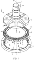
- Fig. 1 An embodiment of a self-aligning virtual elliptical drive, or wobble plate drive, can be seen in Fig. 1 , generally indicated at 10.
- Drive 10 includes an input plate 12, a wobble plate 14, and a stator gear 16.
- Wobble plate 14 has a wobble axis 22 disposed at a non-zero angle relative to the rotation axis, which may be referred to as a wobble angle.
- Wobble plate 14 has a lower, substantially flat face 24 and an upper engaging face 26 with a plurality of face teeth 28. Face teeth 28 are disposed on front face 26, and a plurality of wobble teeth 30 are disposed around a perimeter of the wobble plate between faces 24 and 26, in a plane perpendicular to the wobble axis. The wobble teeth extend parallel to the wobble axis and from face 26 toward face 24.
- Wobble plate 14 is disposed between input plate 12 and stator 16.
- Lower face 24 is perpendicular to the wobble axis and faces generally toward stator 16, while engaging face 26 defines a plane parallel to the lower face but faces generally toward input plate 12.
- Wobble teeth 30 and face teeth 28 extend in opposite directions parallel to wobble axis 22.
- Input plate 12 includes an annular input surface 36 at an outer portion of the input plate, as best seen in Fig. 2 .
- Input surface 36 may be frustoconical. That is, annular input surface 36 is angled relative to a plane perpendicular to the rotation axis 20, so that every point on the annular input surface includes a frustoconical line 38 that can be extended to a vertex located on the rotation axis and below input plate 12.
- the frustoconical vertex of annular input surface 36 is proximate a center of mass of wobble plate 14.
- a plurality or set of input teeth 34 is disposed on annular input surface 36. Any appropriate number of input teeth 34 may be used.
- Each input tooth 34 includes two driving faces 40, 42 and each driving face may be planar, composed of more than one plane, or may be composed of one or more surfaces with curvature.
- front face 26 of wobble plate 14 includes an annular wobble surface 64 at an outer portion of the front face, similar to annular input surface 36 shown in Fig. 2 .
- annular wobble surface 64 is angled relative to a plane perpendicular to wobble axis 22, so that every point on the annular wobble surface includes a frustoconical line that can be extended to a frustoconical vertex located on the wobble axis.
- the frustoconical vertex of annular wobble surface 64 coincides with a center of mass of wobble plate 14.
- the wobble surface may have a different shape.
- Wobble plate 14 is configured to engage with input plate 12. More specifically, face teeth 28 are configured to engage with input teeth 34. When the input plate rotates in a given rotation direction a driving face of an input tooth may engage with a driven face of a face tooth. That is, there may be a contact force exerted on the wobble plate by the input plate through an interaction between the driving faces of the plurality of input teeth and the driven faces of the plurality of face teeth. These contact forces may cause the wobble plate to rotate in the same given rotation direction.
- Wobble plate 14 and input plate 12 may be configured so that any contact forces exerted between the wobble plate and the input plate will point in directions that are tangent to circles which lie in planes perpendicular to the rotation axis.
- eccentric forces may be avoided. Eccentric forces may cause the plurality of face teeth 28 to disengage from the plurality of input teeth 34 or may cause the center of mass of the wobble plate to oscillate, thereby introducing undesirable vibrations into the drive.
- frustoconical input surface 36 and wobble surface 64 cause input teeth 34 and face teeth 28 to engage at an angle such that if drive 10 experiences vibration or displacement, contact forces between the teeth urge input plate 12 and wobble plate 14 back into alignment. Input teeth 34 and face teeth 28 therefore engage in a self-aligning manner, such that the wobble angle remains constant as the input plate and wobble plate rotate.
- stator gear 16 has a base 48, and the base includes an inner cylindrical surface 50 and a stator tooth base 52.
- Base 48 may include attachment points configured to operatively couple stator 16 to the rest of a device using drive 10 (for example, a device within which drive 10 is incorporated).
- Stator 16 may be stationary relative to that device.
- the stator gear defines a stator axis 54 that is substantially aligned with rotation axis 20.
- Stator 16 has an interior volume 56 partially defined by inner cylindrical surface 50. Interior volume 56 may be configured to accommodate some or all of wobble plate 14, as described in more detail below.
- Stator teeth 32 may be disposed on either or both of inner cylindrical surface 50 and stator tooth base 52.
- the stator teeth extend from the inner cylindrical surface into interior volume 56 in a radial direction toward the rotation axis.
- the stator teeth also extend from stator tooth base 52 in an axial direction parallel the rotation axis. Any suitable number of stator teeth may be chosen, depending on the application and desired gear ratio.
- Fig. 3 is a top plan view of stator gear 16, showing a subset of the plurality of stator teeth 32.
- Each tooth of the plurality of stator teeth has a proximal end and a distal end, relative to rotation axis 20. The distal end of a stator tooth may be coupled to inner cylindrical surface 50.
- Each tooth also includes a first engaging surface 66 and on the opposite side of the tooth, a second engaging surface 68.
- Each engaging surface may be planar, composed of more than one plane, or composed of one or more surfaces with curvature.
- One or both engaging surfaces 66, 68 of a stator tooth 32 may be defined by a compound involute of a circle and an ellipse. Alternately, the curve may be the projection of a virtual ellipse onto the tooth location for all angles between 0 and 2 ⁇ radians.
- Each of the plurality of stator teeth 32 is wedge-shaped. That is, the first engaging surface 66 defines a line 70 that is extendable through the rotation axis. Line 70 passes through the center of mass of the wobble plate when both the wobble plate and the stator gear are coupled together within the drive.
- the second engaging surface 68 defines a line 72 that is also extendable through the wobble axis. Line 72 also passes through the center of mass of the wobble plate when both the wobble plate and the stator gear are coupled together within the gearbox system.
- Each tooth of the plurality of stator teeth 32 includes an engaging portion and a supporting base.
- the engaging portion includes the first engaging surface and the second engaging surface.
- the supporting base couples the engaging portion to stator tooth base 52.
- the stator teeth may also be supported by other structures, or coupled to the stator tooth base in any appropriate manner.
- each wobble tooth 30 includes a first engaging surface and on the opposite side of the tooth, a second engaging surface.
- Each surface may be planar, composed of more than one plane, or composed of one or more surfaces with curvature.
- One or both engaging surfaces of a wobble tooth 30 may be defined by a compound involute of a circle and an ellipse. Alternately, the curve may be the projection of a virtual ellipse onto the tooth location for all angles between 0 and 2 ⁇ radians.
- Each of the plurality of wobble teeth is wedge shaped. That is, the first engaging surface defines a first line that is extendable through the wobble axis. The second engaging surface defines a second line that is extendable through the wobble axis. The first and second lines both pass through the center of mass of the wobble plate.
- each wobble tooth 30 includes an engaging portion and a supporting base.
- the engaging portion includes the first engaging surface and the second engaging surface.
- the supporting base connects the engaging portion to wobble tooth base 60.
- the wobble teeth may also be supported by other structures, or coupled to the wobble tooth base in any other appropriate manner
- Wobble plate 14 is configured to engage with stator gear 16. More specifically, wobble teeth 30 are configured to engage with stator teeth 32.
- the first engaging surface of a wobble tooth may engage with the first engaging surface of a stator tooth. That is, there may be a contact force exerted on the wobble plate by the stator gear through an interaction between the first engaging surfaces of the plurality of stator teeth and the first engaging surfaces of the first plurality of wobble teeth. These contact forces may cause the wobble plate to rotate in the first rotation direction and nutate in a first nutation direction.
- the stator gear has n stator teeth and the wobble plate has m wobble teeth, where n and m are integers that differ by one or more, but typically by one.
- n and m are integers that differ by one or more, but typically by one.
- each tooth in the plurality of wobble teeth may engage with one tooth in the plurality of stator teeth during a single nutation.
- the wobble plate may rotate slightly during a single nutation.
- the wobble plate may rotate 1/m of a complete rotation during a single nutation of the wobble plate.
- the wobble plate and the stator gear may interact according to a gear ratio of m:1.
- the gear ratio of the disclosed systems can be determined by the number of teeth m and n of the wobble plate and stator gear, respectively.
- the wobble plate and the stator gear may be configured so that any contact forces exerted between them will point in directions that are tangent to circles which lie in planes perpendicular to the rotation axis.
- Contact forces may point in a direction that is substantially perpendicular to the wobble axis 22 and to a radial line extending from a point of contact between a wobble tooth 30 and a stator tooth 32 to the wobble axis 22.
- stator teeth 32 and wobble teeth 30 define complementary conical surfaces and cause the teeth to engage at an angle such that if drive 10 experiences vibration or displacement, contact forces resulting from engagement urge wobble plate 14 back into alignment with stator gear 16.
- the teeth therefore engage in a self-aligning manner, such that the wobble angle remains constant as the wobble plate nutates about the stator.
- Wobble plate 14 and stator gear 16 are substantially circular in shape, with a projection of the wobble plate onto the stator being elliptical due to their differing orientations.
- the pluralities of wobble teeth 30 and stator teeth 32 may be contoured by projecting this virtual ellipse onto the tooth location.
- the elliptical projection of wobble plate 14 onto stator 16 may thereby be constrained to non-eccentric rotation. Eccentric motion, if allowed, may drive large imbalance forces creating unacceptable system performance.
- the wobble plate drive may be understood as a mechanically constrained system governed by Euler's equations for a wobbling plate, which create a rotating inertial reference frame.
- T z I z ⁇ ⁇ z ⁇ I x ⁇ I y ⁇ x ⁇ y
- T torque
- I moment of inertia
- ⁇ angular velocity
- Wobble teeth 30 and stator teeth 32 may be configured to provide a mechanical constraint on motion of wobble plate 14, for example the engaging surfaces of the teeth may be defined by a compound involute of a circle and an ellipse.
- the maximum possible rotational velocity of the wobble plate is less than or equal to the velocity needed to satisfy the solution to Euler's equations.
- the force is balanced by contact with input plate 12, keeping the wobble angle constant.
- the wobble angle will tend to increase.
- the input plate is spaced from the stator at a predetermined distance such that it constrains the wobble plate relative to the stator gear.
- the wobble angle therefore remains constant and no part of the wobble plate is more than the predetermined distance from the stator gear as the wobble plate nutates around the stator.
- the exemplary wobble plate drives described in the present teachings may either store and absorb input torque, or may output a limited amount of stored torque.
- input teeth 34 of input plate 12 engage face teeth 28 of wobble plate 14 to cause the plate to rotate.
- Wobble teeth 30 of the wobble plate engage stator teeth 32 of stator gear 16 to induce nutation of the wobble plate.
- the wobble plate stores and absorbs the input torque as nutation.
- the wobble plate drive may be considered in terms of the virtual ellipse formed by projecting the wobble plate onto the stator.
- Wobble plate 14 and stator 16 may have generally one point of contact.
- An edge of the virtual ellipse may define in three dimensions a continuous line of contact of the elliptically interfacing wobble plate and stator.
- the shape of the virtual ellipse may remain unchanged under a nutation of the wobble plate that encompasses four times the angle between the wobble axis 22 and rotation axis 20. Only the rotational frame of the line of contact, defined by Euler's equations, may advance as the nutation occurs.
- Each point on the line of contact may fall on a compound geometrically distorted involute function, and the function may be symmetric under both rotation and nutation, allowing continuous energy transfer to and from the virtual ellipse.
- the virtual ellipse may be static as the inertial frame rotates, with all points on the line of contact rotating in their own horizontal plane at a constant angular rate.
- a point on a radial edge of wobble plate 14 viewed during nutation may exhibit vertical motion with a constantly changing velocity. This change in velocity may require constant acceleration of the inertia of the wobble plate, absorbing kinetic energy input to the system.
- the first driven face of a wobble tooth may engage with the first driving face of an input tooth. That is, there may be a contact force exerted on the input plate by the wobble plate through an interaction between the first driven faces of the plurality of face teeth and the first driving faces of the plurality of input teeth. These contact forces may cause the input plate to rotate in the first direction.
- the input plate may be considered an output plate.
- Drive 110 includes an input motor 112, a wobble plate 114, a stator gear 116, and an output plate 118.
- Motor 112 defines a rotation axis 120, about which stator gear 116 and output plate 118 are centered.
- Wobble plate 114 is disposed at a non-zero angle relative to the rotation axis.
- Wobble plate 114 has a rear, substantially flat face 124 and a front face 126 with a plurality of face teeth 128 and a plurality of wobble teeth 130. Face teeth 128 are disposed on front face 126, and wobble teeth 130 are disposed around a perimeter of the wobble plate between faces 124 and 126, in a plane perpendicular to the wobble axis. Wobble teeth 130 and face teeth 128 extend in the same direction parallel to wobble axis 122 (shown in Fig. 6 ).
- motor 112 engages with rear face 124 of wobble plate 114 to induce the wobble plate to nutate about stator 116.
- the stator which also may be referred to as a stator gear, includes a plurality of stator teeth 132 configured to engage with wobble teeth 130, and thereby induce the wobble plate to rotate.
- Output plate 118 includes a plurality of output teeth 134 configured to engage with face teeth 128, and the wobble plate thereby induces the output plate to rotate also. In this manner motor 112 may rotate output plate 118 with a torque determined by a first gear ratio between wobble plate 114 and stator 116, and a second gear ratio between wobble plate 114 and output plate 118.
- input motor 112 is an electric motor with a substantially flat surface 136 perpendicular to rotation axis 120 and including a first cartridge bearing 138 and a second cartridge bearing 140 coupled to the flat surface.
- Bearings 138, 140 may be best seen in Fig. 4 .
- the first bearing may be angularly spaced from the second bearing by 89 degrees, as measured with respect to axis of rotation 120.
- the bearings may be coupled to flat surface 136 proximate a radial edge of the surface.
- Bearings 138, 140 extend from surface 136 such that either bearing 138 or bearing 140 is in contact with rear face 124 of the wobble plate. This contact is at a point angularly spaced by 45 degrees, as measured with respect to the axis of rotation, from a point of closest approach between the motor and the wobble plate.
- the bearings are configured to make rolling contact with rear face 124 of wobble plate 114, and thereby engage with the wobble plate to induce nutation.
- a single rounded protrusion may be formed on flat surface 136 of motor 112.
- the rounded protrusion may make contact with wobble plate 114 at a point angularly spaced from the point of closest approach by 45 degrees, as measured with respect to the axis of rotation.
- Other embodiments may include two protrusions spaced apart by an angle between 80 and 100 degrees, but not necessarily exactly 89 degrees.
- Still other embodiments may include three or more projections extending from flat surface 136.
- a lubricant may be disposed between motor 112 and wobble plate 114, to reduce friction between the rounded protrusions and rear face 124 of the wobble plate.
- the protrusions may take any shape, or include any mechanism tending to provide low friction rolling engagement of the protrusion(s) with wobble plate 114.
- wobble plate 114 is shaped similarly to a disc, with a rear face 124, a front face 126 and a central axis, or wobble axis 122.
- Wobble plate 114 is aligned such that wobble axis 122 forms a non-zero angle with axis of rotation 120.
- Rear face 124 is perpendicular to the axis of rotation, while front face 126 defines a plane parallel to the rear face.
- rear face 124 faces generally toward input motor 112 and front face 126 faces generally away from the motor.
- the plurality of wobble teeth 130 are disposed around a perimeter of wobble plate 114 between rear face 124 and front face 126 and in a plane perpendicular to wobble axis 122.
- the wobble teeth extend from an outer cylindrical surface 158 of the wobble plate in a radial direction away from the wobble axis.
- the wobble teeth also extend from a wobble tooth base 160 in an axial direction along the wobble axis.
- the wobble tooth base may be an approximately annular member coupled to or integral with the wobble plate.
- the plurality of wobble teeth may extend from both cylindrical surface 158 and wobble tooth base 160. Connecting the wobble teeth to either or both of the cylindrical surface or the wobble tooth base may lend physical support or a degree of rigidity to the plurality of wobble teeth. Any suitable number of wobble teeth 130 may be chosen.
- Each wobble tooth 130 includes a first engaging surface and on the opposite side of the tooth, a second engaging surface.
- Each surface may be planar, composed of more than one plane, or composed of one or more surfaces with curvature.
- One or both engaging surfaces of a wobble tooth 130 may be defined by a compound involute of a circle and an ellipse, as will be discussed in more detail below. Alternately, the curve may be the projection of a virtual ellipse onto the tooth location for all angles between 0 and 2 ⁇ radians.
- each wobble tooth 130 includes an engaging portion and a supporting base.
- the engaging portion includes the first engaging surface and the second engaging surface.
- the supporting base connects the engaging portion to wobble tooth base 160.
- Equation (2) above may be normalized to a radius of the wobble plate.
- the curve of the second engaging surface may be the projection of a virtual ellipse onto the tooth location for all angles between 0 and 2 ⁇ radians.
- the curve of the first engaging surface may be a mirror image of the curve of the second engaging surface, reflected across a plane through the apex of the tooth and containing the axis of rotation.
- the first engaging surface and the second engaging surface may meet smoothly at the apex of each tooth.
- the cross-sectional shape of the tooth may therefore be defined by a compound involute of a circle and an ellipse.
- a plurality or set of face teeth 128 is disposed on annular wobble surface 164. Any suitable number of face teeth 128 may be chosen, and the number of face teeth may be more, less, or the same as the number of output teeth 134. In the depicted embodiment, there are equal numbers of face teeth 128 and output teeth 134.
- Each face tooth includes two driving faces, which may be planar, composed of more than one plane, or may be composed of one or more surfaces with curvature.
- Stator 116 has an interior volume 156 which is partially defined by inner cylindrical surface 150. Interior volume 156 may be configured to accommodate some or all of wobble plate 114 as described in more detail below.
- Each tooth of the plurality of stator teeth may have a proximal end and a distal end, relative to rotation axis 120.
- the distal end of a stator tooth may be coupled to inner cylindrical surface 150.
- Each tooth includes a first engaging surface and on the opposite side of the tooth, a second engaging surface.
- Each engaging surface may be planar, composed of more than one plane, or composed of one or more surfaces with curvature.
- Each tooth of the plurality of stator teeth 132 includes an engaging portion and a supporting base.
- the engaging portion includes the first engaging surface and the second engaging surface.
- the supporting base couples the engaging portion to stator tooth base 152.
- output plate 118 includes a plurality of output teeth 134 disposed on an annular output surface 162. Output plate 118 also has an output axis substantially aligned with rotation axis 120.
- output surface 162 is frustoconical. That is, annular output surface 162 is angled relative to a plane perpendicular to the rotation axis 120, so that every point on the annular output surface includes a frustoconical line that can be extended to a frustoconical vertex located on the rotation axis and forward of output plate 118.
- the frustoconical vertex of annular output surface 162 coincides with a center of mass of wobble plate 114.
- the output surface may have different shapes, such as cylindrical or frustoconical with a different vertex.
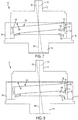
- Figs. 7-8 are cross-sectional views of drive 110, showing motor 112, wobble plate 114, stator gear 116, and output plate 118 in an assembled configuration.
- the motor and output plate are aligned along stator axis 154. That is, the rotation axis, the output axis, and the stator axis are substantially aligned.
- the wobble plate and wobble axis 122 may be disposed at any desired and suitable non-zero angle relative to the stator axis. As wobble plate 114 nutates around stator 116 and output plate 118, the center of mass of the wobble plate is substantially stationary.
- Fig. 8 is a cross-section in a plane rotated 45 degrees from the plane of the cross-section of Fig. 7 , about stator axis 154, and the angle in each has been exaggerated to more clearly show relationships between components.
- Wobble plate 114 is configured to engage with stator gear 116. More specifically, wobble teeth 130 are configured to engage with stator teeth 132. In the case where motor 112 rotates in a first rotation direction, the first engaging surface of a wobble tooth may engage with the first engaging surface of a stator tooth. That is, there may be a contact force exerted on the wobble plate by the stator gear through an interaction between the first engaging surfaces of the plurality of stator teeth and the first engaging surfaces of the first plurality of wobble teeth. These contact forces may cause the wobble plate to rotate in the first rotation direction and nutate in a first nutation direction.
- the wobble plate may rotate 1/ m of a complete rotation during a single nutation of the wobble plate.
- the wobble plate and the stator gear may interact according to a gear ratio of m :1.
- the gear ratio of the disclosed systems can be determined by the number of teeth m and n of the wobble plate and stator gear, respectively.
- the wobble plate and the stator gear may be configured so that any contact forces exerted between them will point in directions that are tangent to circles which lie in planes perpendicular to the rotation axis.
- Contact forces may point in a direction that is substantially perpendicular to the wobble axis 122 and to a radial line extending from a point of contact between a wobble tooth 130 and a stator tooth 132 to the wobble axis 122.
- Wobble plate 114 and stator gear 116 are substantially circular in shape, with a projection of the wobble plate onto the stator being elliptical in shape due to their differing orientations.
- the pluralities of wobble teeth 130 and stator teeth 132 may be contoured by projecting this virtual ellipse onto the tooth location.
- the elliptical projection of wobble plate 114 onto stator 116 may thereby be constrained to non-eccentric rotation. Eccentric motion, if allowed, may drive large imbalance forces creating unacceptable system performance.
- Wobble plate 114 is also configured to engage with output plate 118, through engagement of face teeth 128 and output teeth 134.
- the first driving face of a wobble tooth may engage with the first driven face of an output tooth. That is, there may be a contact force exerted on the output plate by the wobble plate through an interaction between the first driving faces of the plurality of face teeth and the first driven faces of the plurality of output teeth. These contact forces may cause the output plate to rotate in the first rotation direction.
- contact forces between the second driving faces of the wobble teeth and the second driven faces of the output teeth may cause the output plate to rotate in the second rotation direction.
- the output plate and the wobble plate have the same number of teeth, i.e., the number of output teeth is equal to the number of face teeth. Accordingly, in the depicted embodiment, the output plate and the wobble plate interact and rotate according to a gear ratio of 1:1. That is, for every complete rotation of the wobble plate, the output plate also completes exactly one complete rotation. Other choices for the numbers of output and face teeth are possible and would lead to other values for the output gear ratio.
- Wobble plate 114 and output plate 118 may be configured so that any contact forces exerted between them will point in directions that are tangent to circles which lie in planes perpendicular to the rotation axis.
- a contact force may point in a direction that is substantially perpendicular to the wobble axis 122 and to radial line extending from a point of contact between a face tooth 128 and an output tooth 134 to the wobble axis 122.
- eccentric forces may be avoided. Eccentric forces may cause the plurality of face teeth to disengage from the plurality of output teeth or may cause the center of mass of the wobble plate to oscillate, thereby introducing undesirable vibrations into the drive system.
- Wobble plate 114 may have a 0-degree position or point 142 which may be the position or point on the wobble plate which is farthest from output plate 118, as measured in a direction parallel to rotation axis 120. At the 0-degree position, shown in Fig. 7 , the wobble plate 114 may be closest to motor 112. Wobble plate 114 may have a 90-degree position or point which may be one-fourth of the way around the wobble plate from the 0-degree position in a first nutation direction. For example, as viewed from a vantage point above the wobble plate near the output plate, the 90-degree position may be ninety degrees around a perimeter of the wobble plate in a counter-clockwise direction.
- a 180-degree position or point 144 may be located on the opposite side of the wobble plate as the 0-degree position 142.
- the 180-degree position may mark the closest approach of the wobble plate to the output plate and the stator gear and the point of farthest distance from the motor.
- a 270-degree position or point may be located on the opposite side of the wobble plate as the 90-degree position.
- Motor 112 may be disposed such that 0-degree point 142 is in contact with flat surface 136 of the motor between bearings 138, 140 (not shown) at a given instant of time, as depicted in Fig. 7 . At that same instant of time, only one of bearings 138, 140 may be in contact with rear face 124 of wobble plate 114 at a point 146, as depicted in Fig. 8 .
- the motor may be configured to rotate the bearings around stator axis 154 and thereby cause wobble plate 114 to nutate around stator gear 116, with wobble axis 122 precessing around the stator axis. The point of contact 146 between the bearing and wobble plate 114 may therefore move ahead of 180-degree point 144.
- bearing 138 may be in contact with rear face 124 of the wobble plate at a point between 0-degree position 142 and the 270-degree position and may engage with the wobble plate to cause the wobble plate to nutate in a first direction.
- Fig. 8 shows bearing 138 in such a case.
- bearing 140 may be in contact with rear face 124 of the wobble plate at a point between 0-degree position 142 and the 90-degree position and may engage with the wobble plate to cause the wobble plate to nutate in a second direction.
- wobble plate 114 When drive 110 is in use, wobble plate 114 will generally nutate and also rotate.
- the wobble plate may be described as configured to nutate around stator gear 116, around motor 112, and/or around output plate 118.
- the 0-degree position of the wobble plate may move toward a current location of the 90-degree position so that, after one quarter of a full nutation, the 90-degree position has become the 0-degree position, the 180-degree position has become the 90-degree position, etc.
- the wobble plate may not rotate at the same rate it nutates. That is, as the wobble plate completes a single full nutation, the 0-degree position may travel the full perimeter of the wobble plate. During this same time, the wobble plate may rotate less than one full rotation. The rate of rotation may be determined by the rate of nutation and by the gear ratio between wobble teeth 130 and stator gear 116.
- Wobble teeth 130 may engage with stator teeth 132 along one-fourth of the stator gear at any moment as the wobble plate nutates. This engagement may be in the form of a rolling contact, where the first engaging surfaces roll along one another. This rolling contact may be in contrast to many standard gear interfaces where opposing faces of gear teeth interact via a sliding contact. In general, assuming the same two surfaces are involved, rolling contact has much less friction than sliding contact between the two surfaces.
- face teeth 128 may only engage with output teeth 134 along one-fourth of the output plate at any moment as the wobble plate nutates.
- the face teeth and output teeth may engage between 180-degree position 144 and the 90 degree position.
- wobble plate 114 may cause output plate 118 to rotate in the same direction as the wobble plate.
- output plate 118 may also rotate at the same rate as wobble plate 114. Rotation of motor 112 thus may be transferred to output plate 118 at a higher torque.
- Fig. 9 is a schematic representation of a motor 212 and a wobble plate 214 of another embodiment of a self-aligning virtual elliptical drive, generally indicated at 210.
- the embodiment of Fig. 9 may be similar to wobble plate drive 110 described in Example 2, and the discussion of various features and benefits of drive 110 will not be repeated in its entirety with regard to drive 210. Similar components may be numbered similarly, but incremented by 200.
- Wobble plate 214 has a wobble axis 222, a substantially flat rear face, a front face with a plurality of face teeth, and a plurality of wobble teeth disposed around a perimeter of the wobble plate between the flat face and the front face.
- the face teeth and wobble teeth are not indicated in Fig. 9 , but may be as shown in Fig. 6 , for example.
- the wobble plate drive further includes an output plate with output teeth and a stator with stator teeth, not pictured, but which may be as previously described in Example 2 (see Figs. 4-5 ).
- Motor 212 has a motor axis 220.
- the wobble plate is configured to nutate around the motor, with the wobble axis precessing around the motor axis. That is, the wobble plate 214 has a mobile point of closest approach 242 with respect to the motor.
- the mobile point of closest approach 242 may move in a direction of nutation, indicated by arrow 243, around the motor axis 220.
- Force 245 is a result of a response of the material of wobble plate 214 to electromagnetic fields created by motor 212.
- the motor includes a permanent magnet and a set of electromagnetic coils.
- the permanent magnet and the set of electromagnetic coils are collectively configured to create a magnetic field between the motor and the wobble plate. That is, a magnetic field is created in a gap 266 between the motor 212 and the wobble plate 214.
- the wobble plate is made of a magnetically susceptible material configured to respond to the magnetic field. Magnetically susceptible materials may become magnetized themselves in the presence of a magnetic field.
- the wobble plate responds by experiencing a force such as force 245.
- Forces applied to the wobble plate may be proportional to the flux density of the magnetic field between the wobble plate and the motor.
- the permanent magnet and the set of electromagnetic coils may be configured to create a magnetic field with a highest flux density at a mobile location ahead of the mobile point of closest approach in the nutation direction 243.
- the electromagnetic coils may be configured so that the highest flux density of magnetic field remains ahead of the mobile point of closest approach as the wobble plate nutates.
- Fig. 10 is a diagrammatic representation of an isometric exploded view of motor 212.
- the motor includes a permanent magnet 268, a motor core 270, a set of magnetically susceptible pole pieces 272, and a set of electromagnetic coils 274. Relative dispositions and orientations of components of motor 212 may be described relative to the motor axis.
- the term “axially” will refer to linear directions which are parallel to motor axis 220.
- the term “radially” will refer to linear directions which are perpendicular to the motor axis 220.
- the term “circumferentially” will refer to angular directions around, but not along or away from, the motor axis.
- Permanent magnet 268 may have any appropriate shape and may be configured to generate any appropriate magnetic field.
- the permanent magnet is cylindrical, with the motor axis 220 as a symmetry axis, and includes a passage 276 through the permanent magnet along the motor axis.
- Permanent magnet 268 may be constructed of any appropriate ferromagnetic material. Permanent magnet 268 has north and south magnetic poles substantially aligned along the motor axis 220. The magnetic field created by the permanent magnet may be referred to as a primary magnetic field.
- Motor core 270 is disposed below the permanent magnet 268.
- Motor core 270 may be formed of a magnetically susceptible material capable of acquiring a magnetic moment when placed in a magnetic field.
- motor core 270 may be made of electrical steel or iron.
- Motor core 270 may have any appropriate shape.
- the motor core is cylindrical, with the motor axis 220 as a symmetry axis and a radius matching a radius of the permanent magnet 268.
- the motor core includes a passage 278 aligned with passage 276 through the permanent magnet.
- Motor 212 includes a horizontal spacer 280 disposed between the permanent magnet 268 and the motor core 270.
- Horizontal spacer 280 may limit the magnetic field transferred from the permanent magnet to the motor core and may help regulate the magnitude of the magnetic field created by motor 212.
- the set of magnetically susceptible pole pieces 272 are distributed circumferentially around the motor core 270.
- the pole pieces 272 may direct magnetic fields within motor 212 from one component of the motor to another.
- the pole pieces may be made of any suitable magnetically susceptible material, such as electrical steel.
- the embodiment shown in Fig. 10 includes twelve pole pieces.
- the pole pieces may have any appropriate shape.
- the twelve pole pieces shown in Fig. 10 are wedge-shaped and may alternately be described as wedge pieces.
- the pole pieces 272 are separated by a set of vertical spacers 282, which help to isolate magnetic fields in the pole pieces between the vertical spacers.
- the set of magnetically susceptible pole pieces 272 collectively have an upper surface area 284.
- the pole pieces may be sized and configured so that the magnitude of the upper surface area is a predetermined multiple of an upper surface area of the permanent magnet 268.
- the upper surface area 284 of the pole pieces may be three times the upper surface area of the permanent magnet.
- the set of electromagnetic coils 274 are disposed circumferentially around the motor core 270 and between the motor core and the magnetically susceptible pole pieces 272.
- the set of electromagnetic coils includes a first set of electromagnetic coils and a second set of electromagnetic coils.
- the first set of electromagnetic coils includes three inner electromagnetic coils 286 and the second set of electromagnetic coils includes three outer electromagnetic coils 288.
- the three outer electromagnetic coils 288 are disposed between the inner electromagnetic coils 286 and the set of magnetically susceptible pole pieces 272.
- the first and second sets of electromagnetic coils may include any appropriate number of coils, including two, three, and more than three coils. The numbers of coils in the first and second sets of electromagnetic coils need not be the same.
- Each of the first set of electromagnetic coils 286 overlaps circumferentially with each of an adjacent pair of electromagnetic coils of the second set of electromagnetic coils 288.
- Each of the second set of electromagnetic coils 288 overlaps circumferentially with each of an adjacent pair of electromagnetic coils of the first set of electromagnetic coils 286.
- Each of the set of electromagnetic coils 274 has a coil axis 290 oriented perpendicularly to the motor axis 220.
- Each electromagnetic coil includes one or more conductors forming a plurality of closed loops around the coil axis 290. When each of the set of electromagnetic coils carries an electrical current, each coil creates a magnetic field within the coil oriented substantially parallel to the coil axis.
- inner and outer electromagnetic coils 286 and 288 overlap circumferentially as described above, magnetic field lines created by one of the electromagnetic coils may pass through one or more closed loops defined by another of the electromagnetic coils. Portions of the magnetic field created by one of the inner electromagnetic coils 286 may pass through each of an adjacent pair of outer electromagnetic coils 288. If there is an angular gap 292 between the adjacent pair of outer electromagnetic coils, then a portion of the magnetic field created by the inner electromagnetic coil may not pass through either of the adjacent pair of outer electromagnetic coils.
- portions of the magnetic field created by one of the outer electromagnetic coils 288 may pass through each of an adjacent pair of inner electromagnetic coils 286. If there is an angular gap 294 between the adjacent pair of inner electromagnetic coils, then a portion of the magnetic field created by the outer electromagnetic coil may not pass through either of the adjacent pair of inner electromagnetic coils.
- Motor 212 includes an upper member 296 disposed over the permanent magnet and the set of magnetically susceptible pole pieces 272.
- the upper member may cover the upper surface area of the pole pieces and the upper surface area of the permanent magnet.
- the upper member includes a passage 298 substantially aligned with the passage 276 through the permanent magnet.
- Upper member 296 may be made of any appropriate material, such as magnetically susceptible material such as electrical steel.
- Wobble plate 214 is disposed with the substantially flat rear face proximate upper member 296 with a gap between the motor and the wobble plate. Magnetic field lines exit the motor through the upper member in a substantially axial direction, traverse the gap between the motor and the wobble plate, travel through the wobble plate, again traverse the gap between the wobble plate and the motor, and enter the motor through the upper member in a substantially axial direction.
- motor 212 When motor 212 induces wobble plate to nutate the wobble teeth of wobble plate 214 and stator teeth of the stator may engage to cause the wobble plate to rotate.
- the face teeth of wobble plate 214 and output teeth of the output plate may engage to cause the output plate to rotate in the same direction as the wobble plate. Electromagnetic energy of motor 212 may thus be converted to rotation of the output plate.
- Fig. 11 depicts a method, generally indicated at 300, for operating a self-aligning virtual elliptical drive.
- method 300 includes providing an input plate with input teeth, providing a wobble plate with wobble teeth and face teeth, and providing a stator gear with stator teeth.
- the input plate, wobble plate, and stator gear may be constructed and assembled as shown, for example, in Fig. 1 and described above in example 1, or in any other suitable manner and configuration consistent with the present teachings.
- method 300 includes rotating the input plate about a rotation axis.
- method 300 includes engaging the input teeth with the face teeth, thereby causing the wobble plate to rotate.
- the input teeth and the face teeth may be disposed on frustoconical surfaces forming two complementary cones, such that engagement of the teeth causes the complementary cones to return to alignment.
- method 300 includes engaging the wobble teeth with the stator teeth, thereby causing the wobble plate to nutate.
- the wobble teeth and the stator teeth may be wedge shaped, the teeth forming two complementary cones, such that the engagement of the teeth causes the complementary cones to return to alignment.
- the input plate may be spaced from the stator at a predetermined distance in order to constrain the wobble plate relative to the stator gear, such that the wobble angle remains constant and no part of the wobble plate can be more than the predetermined distance from the stator gear.
- the method may include dissipating rotational energy by nutating the wobble plate. In other embodiments, the method may further include stopping rotation of the input plate, and then allowing inertial energy of the nutating and rotating wobble plate to rotate the input plate.
- Fig. 12 depicts another method, generally indicated at 400, for operating a self-aligning virtual elliptical drive.
- method 400 includes providing a motor which may include at least one rounded protrusion on a substantially flat surface and may define a rotation axis, providing a wobble plate with wobble teeth and face teeth, providing a stator gear with stator teeth, and providing an output plate with output teeth.
- the motor, wobble plate, stator gear and output plate may be constructed and assembled as shown, for example, in Figs. 4-8 and described above in example 2, or in any other suitable manner and configuration consistent with the present teachings.
- method 400 includes energizing the motor, which may rotate about the rotation axis.
- method 400 includes engaging the motor with the wobble plate. The engagement may consist of engaging one or more of the rounded protrusions of the motor with a substantially flat surface of the wobble plate, thereby causing the wobble plate to nutate.
- method 400 includes engaging the wobble teeth with the stator teeth, thereby causing the wobble plate to rotate.
- method 400 includes engaging the face teeth of the wobble plate with the output teeth of the output plate, thereby causing the output plate to rotate.
- the input teeth and the face teeth may be disposed on frustoconical surfaces forming two complementary cones, such that engagement of the teeth causes the complementary cones to return to alignment.
- the wobble teeth and the stator teeth may be wedge shaped, the teeth forming two complementary cones, such that the engagement of the teeth causes the complementary cones to return to alignment.
- the method may further include stopping rotation of the motor and allowing the output plate to come to a stop.
- the method may further include energizing the motor to rotate in a second rotation direction about the rotation axis, thereby rotating the output plate in a second direction.
- Method 400 may also be used for operating a self-aligning virtual elliptical drive consistent with the configuration described in example 3.
- method 400 may include providing a motor having a permanent magnet and a set of electromagnetic coils defining a central axis, providing a wobble plate of a magnetically susceptible material with wobble teeth and face teeth, providing a stator gear with stator teeth, and providing an output plate with output teeth.
- the motor, wobble plate, stator gear and output plate may be constructed and assembled as described above in example 3, or in any other suitable manner and configuration consistent with the present teachings.
- method 400 may include energizing the motor, which creates a magnetic field between the motor and the wobble plate with a highest flux density at a mobile location.
- method 400 in this case includes engaging the motor with the wobble plate by magnetizing the magnetically susceptible material of the wobble plate with the magnetic field of the motor and thereby applying a force on the wobble plate. The force may be applied at the mobile location of highest flux density, leading a point of closest approach between the wobble plate and the motor, and causing the wobble plate to nutate.
- method 400 includes engaging the wobble teeth with the stator teeth, thereby causing the wobble plate to rotate.
- method 400 includes engaging the face teeth of the wobble plate with the output teeth of the output plate, thereby causing the output plate to rotate.
- the method may further include stopping rotation of the motor and allowing the output plate to come to a stop.
- the method may further include energizing the motor to move the mobile location of highest flux density in an opposite direction, thereby rotating the output plate in a second direction.
- Methods of use according to the present teachings may be employed in conjunction with any of the mechanical virtual elliptical drive embodiments previously described. Although various steps of methods 300 and 400 have been described and are depicted in Figs. 11-12 , the steps need not necessarily all be performed, in some cases may be performed in a different order than the order shown, and in some cases may be performed simultaneously.
- a self-aligning wobble plate drive described herein provide several advantages over known solutions for designing compact and cost effective wobble plate drives.
- the illustrative embodiments of a self-aligning wobble plate drive described herein allow a drive without a supporting shaft or fulcrum.
- illustrative embodiments of the self-aligning wobble plate described herein reduce vibration, heat produced by friction, and binding of gear teeth. No known system or device can perform these functions, particularly in such a small volume.
- not all embodiments described herein provide the same advantages or the same degree of advantage.
Landscapes
- Engineering & Computer Science (AREA)
- General Engineering & Computer Science (AREA)
- Mechanical Engineering (AREA)
- Power Engineering (AREA)
- Retarders (AREA)
- Connection Of Motors, Electrical Generators, Mechanical Devices, And The Like (AREA)
- General Electrical Machinery Utilizing Piezoelectricity, Electrostriction Or Magnetostriction (AREA)
- Gears, Cams (AREA)
- Transmission Devices (AREA)
- Gripping On Spindles (AREA)
- Bipolar Transistors (AREA)
Abstract
Description
- This disclosure relates to wobble plate drives. More specifically, the disclosed embodiments relate to systems and methods for modifying torque with an elliptically interfacing gear system.
- Two or more gears can be used to create a mechanical advantage through a gear ratio. There are many ways to arrange gears so that a single rotation of a first gear results in more or less than one rotation of a second gear in the same amount of time. In certain applications it is desirable to have a motor with a very high gear ratio, where the gear reduction takes place in the smallest possible volume.
- Historically, wobble plate drive mechanisms have seemed a promising route toward a drive having a high gear ratio within a small volume. In a wobble plate drive, one of the gears, for example a rotor gear, nutates around the other gear, for example a stator gear. As used herein, the terms "nutate" or "nutation" mean a wobble, a sway, or a circular rocking motion. The rotor gear is typically supported by a shaft or fulcrum that keeps the gear teeth in alignment. If the number of gear teeth on the rotor gear and the stator gear are different by one, then such a system would have a gear ratio equal to the number of teeth on the stator gear.
- In practice, efficient and effective wobble plate drive systems have proven to be elusive, because the forces involved often lead to disengagement of the mechanism, binding, over-constraint by the fulcrum, or inefficiency due to friction, among others.
- A self-aligning wobble plate drive includes a stator gear, a wobble plate, and an output plate. The stator gear has a central stator axis and a plurality of stator teeth disposed on an inner cylindrical surface. The wobble plate has a wobble axis, an engaging face perpendicular to the wobble axis, a plurality of face teeth disposed on the engaging face, and a plurality of wobble teeth disposed around a perimeter of the wobble plate and configured to engage with the stator teeth. The output plate includes a plurality of output teeth configured to engage with the face teeth.
- The wobble plate is disposed such that the wobble axis is at a non-zero wobble angle relative to the stator axis, and the output plate is substantially aligned with the stator axis. At least two of the pluralities of teeth are configured to engage with each other in a self-aligning manner such that as the wobble plate nutates around the stator gear, the wobble angle remains constant.
- A method for operating a self-aligning wobble plate drive includes providing a stator gear, a wobble plate, and an output plate. The method further includes engaging a plurality of stator teeth of the stator gear with a plurality of wobble teeth of the wobble plate in a self-aligning manner. The method then includes engaging a plurality of face teeth of the wobble plate with a plurality of output teeth of the output plate in a self-aligning manner. Finally, the method includes inducing nutation of the wobble plate about the stator gear.
- The present disclosure provides various apparatuses and methods of use thereof. In some embodiments, a wobble plate drive may include an input plate, a wobble plate, and a stator. In some embodiments, a drive may include a motor, a wobble plate, a stator, and an output plate. In some embodiments, each of the wobble plate, the stator gear, and the input plate or output plate may include a set of teeth configured to engage with each other in a self-aligning manner.
- Features, functions, and advantages may be achieved independently in various embodiments of the present disclosure, or may be combined in yet other embodiments, further details of which can be seen with reference to the following description and drawings.
-
-
Fig. 1 is an exploded isometric view of an exemplary wobble plate drive, according to aspects of the present disclosure. -
Fig. 2 is a magnified bottom plan view of a portion of an input plate of the wobble plate drive ofFig. 1 . -
Fig. 3 is a magnified top plan view of a portion of a stator gear of the wobble plate drive ofFig. 1 . -
Fig. 4 is an exploded isometric front view of another exemplary wobble plate drive, according to aspects of the present disclosure. -
Fig. 5 is an exploded isometric rear view of the wobble plate drive ofFig. 4 . -
Fig. 6 is an isometric view of a wobble plate drive of the wobble plate drive ofFig. 4 . -
Fig. 7 is a cross-sectional view of the wobble plate drive ofFig. 4 , taken along a plane parallel to a rotation axis of the drive. -
Fig. 8 is another cross-sectional view of the wobble plate drive ofFig. 4 , taken along a plane rotated 45 degrees from the plane ofFig. 7 . -
Fig. 9 is a schematic representation of an isometric view of a wobble plate and a motor, according to aspects of the present disclosure. -
Fig. 10 is a diagrammatic representation of an isometric exploded view of the motor ofFig. 9 . -
Fig. 11 is a flow chart depicting an exemplary method of use of a wobble plate drive, according to aspects of the present disclosure. -
Fig. 12 is a flow chart depicting another exemplary method of use of a wobble plate drive, according to aspects of the present disclosure. - Various embodiments of a self-aligning wobble plate drive having a wobble plate and a stator are described below and illustrated in the associated drawings. Unless otherwise specified, a wobble plate drive and/or its various components may, but are not required to, contain at least one of the structure, components, functionality, and/or variations described, illustrated, and/or incorporated herein. Furthermore, the structures, components, functionalities, and/or variations described, illustrated, and/or incorporated herein in connection with the present teachings may, but are not required to, be included in other wobble plate drives. The following description of various embodiments is merely exemplary in nature and is in no way intended to limit the disclosure, its application, or uses. Additionally, the advantages provided by the embodiments, as described below, are illustrative in nature and not all embodiments provide the same advantages or the same degree of advantages.
- The following sections describe selected aspects of exemplary wobble plate drives as well as related systems and/or methods. The examples in these sections are intended for illustration and should not be interpreted as limiting the entire scope of the present disclosure. Each section may include one or more distinct inventions, and/or contextual or related information, function, and/or structure.
- An embodiment of a self-aligning virtual elliptical drive, or wobble plate drive, can be seen in
Fig. 1 , generally indicated at 10. Drive 10 includes aninput plate 12, awobble plate 14, and astator gear 16.Input plate 12, which may also be referred to an output plate depending on the intended use of the wobble plate drive, defines arotation axis 20 about whichstator gear 16 is centered. Wobbleplate 14 has awobble axis 22 disposed at a non-zero angle relative to the rotation axis, which may be referred to as a wobble angle. - Wobble
plate 14 has a lower, substantiallyflat face 24 and an upperengaging face 26 with a plurality offace teeth 28.Face teeth 28 are disposed onfront face 26, and a plurality ofwobble teeth 30 are disposed around a perimeter of the wobble plate betweenfaces face 26 towardface 24. - Wobble
plate 14 is disposed betweeninput plate 12 andstator 16.Lower face 24 is perpendicular to the wobble axis and faces generally towardstator 16, whileengaging face 26 defines a plane parallel to the lower face but faces generally towardinput plate 12. Wobbleteeth 30 andface teeth 28 extend in opposite directions parallel towobble axis 22. -
Input plate 12 includes an annular input surface 36 at an outer portion of the input plate, as best seen inFig. 2 . Input surface 36 may be frustoconical. That is, annular input surface 36 is angled relative to a plane perpendicular to therotation axis 20, so that every point on the annular input surface includes afrustoconical line 38 that can be extended to a vertex located on the rotation axis and belowinput plate 12. When the above-recited elements are assembled into a wobble plate drive, the frustoconical vertex of annular input surface 36 is proximate a center of mass ofwobble plate 14. - A plurality or set of
input teeth 34 is disposed on annular input surface 36. Any appropriate number ofinput teeth 34 may be used. Eachinput tooth 34 includes two driving faces 40, 42 and each driving face may be planar, composed of more than one plane, or may be composed of one or more surfaces with curvature. - As depicted in
Fig. 1 ,front face 26 ofwobble plate 14 includes anannular wobble surface 64 at an outer portion of the front face, similar to annular input surface 36 shown inFig. 2 . In other words,annular wobble surface 64 is angled relative to a plane perpendicular to wobbleaxis 22, so that every point on the annular wobble surface includes a frustoconical line that can be extended to a frustoconical vertex located on the wobble axis. The frustoconical vertex ofannular wobble surface 64 coincides with a center of mass ofwobble plate 14. In other embodiments, the wobble surface may have a different shape. - A plurality or set of
face teeth 28 is disposed onannular wobble surface 64. Any suitable number offace teeth 28 may be chosen, and the number of face teeth may be more, less, or the same as the number ofinput teeth 34. In the depicted embodiment, there are equal numbers offace teeth 28 andinput teeth 34. Each face tooth includes two driven faces, which may be planar, composed of more than one plane, or may be composed of one or more surfaces with curvature. -
Wobble plate 14 is configured to engage withinput plate 12. More specifically, faceteeth 28 are configured to engage withinput teeth 34. When the input plate rotates in a given rotation direction a driving face of an input tooth may engage with a driven face of a face tooth. That is, there may be a contact force exerted on the wobble plate by the input plate through an interaction between the driving faces of the plurality of input teeth and the driven faces of the plurality of face teeth. These contact forces may cause the wobble plate to rotate in the same given rotation direction. - In the example of
drive 10,input plate 12 andwobble plate 14 interact and rotate according to a gear ratio of 1:1. That is, for every single complete rotation of the input plate, the wobble plate also completes exactly one complete rotation. Other choices for the gear ratio are possible, and would result in differing rates of rotation. -
Wobble plate 14 andinput plate 12 may be configured so that any contact forces exerted between the wobble plate and the input plate will point in directions that are tangent to circles which lie in planes perpendicular to the rotation axis. By configuring the wobble plate and input plate so that contact forces between the wobble plate and the input plate point in such directions, eccentric forces may be avoided. Eccentric forces may cause the plurality offace teeth 28 to disengage from the plurality ofinput teeth 34 or may cause the center of mass of the wobble plate to oscillate, thereby introducing undesirable vibrations into the drive. - The complementary shapes of frustoconical input surface 36 and
wobble surface 64cause input teeth 34 and faceteeth 28 to engage at an angle such that ifdrive 10 experiences vibration or displacement, contact forces between the teeth urgeinput plate 12 andwobble plate 14 back into alignment.Input teeth 34 and faceteeth 28 therefore engage in a self-aligning manner, such that the wobble angle remains constant as the input plate and wobble plate rotate. - As shown in
Fig. 1 ,stator gear 16 has abase 48, and the base includes an innercylindrical surface 50 and astator tooth base 52.Base 48 may include attachment points configured to operatively couplestator 16 to the rest of a device using drive 10 (for example, a device within which drive 10 is incorporated).Stator 16 may be stationary relative to that device. The stator gear defines astator axis 54 that is substantially aligned withrotation axis 20. -
Stator 16 has aninterior volume 56 partially defined by innercylindrical surface 50.Interior volume 56 may be configured to accommodate some or all ofwobble plate 14, as described in more detail below. -
Stator teeth 32 may be disposed on either or both of innercylindrical surface 50 andstator tooth base 52. In the embodiment ofFig. 1 , the stator teeth extend from the inner cylindrical surface intointerior volume 56 in a radial direction toward the rotation axis. The stator teeth also extend fromstator tooth base 52 in an axial direction parallel the rotation axis. Any suitable number of stator teeth may be chosen, depending on the application and desired gear ratio. -
Fig. 3 is a top plan view ofstator gear 16, showing a subset of the plurality ofstator teeth 32. Each tooth of the plurality of stator teeth has a proximal end and a distal end, relative torotation axis 20. The distal end of a stator tooth may be coupled to innercylindrical surface 50. Each tooth also includes a first engagingsurface 66 and on the opposite side of the tooth, a secondengaging surface 68. Each engaging surface may be planar, composed of more than one plane, or composed of one or more surfaces with curvature. One or both engagingsurfaces stator tooth 32 may be defined by a compound involute of a circle and an ellipse. Alternately, the curve may be the projection of a virtual ellipse onto the tooth location for all angles between 0 and 2π radians. - Each of the plurality of
stator teeth 32 is wedge-shaped. That is, the first engagingsurface 66 defines aline 70 that is extendable through the rotation axis.Line 70 passes through the center of mass of the wobble plate when both the wobble plate and the stator gear are coupled together within the drive. The secondengaging surface 68 defines aline 72 that is also extendable through the wobble axis.Line 72 also passes through the center of mass of the wobble plate when both the wobble plate and the stator gear are coupled together within the gearbox system. - Each tooth of the plurality of
stator teeth 32 includes an engaging portion and a supporting base. The engaging portion includes the first engaging surface and the second engaging surface. The supporting base couples the engaging portion tostator tooth base 52. The stator teeth may also be supported by other structures, or coupled to the stator tooth base in any appropriate manner. - As shown in
Fig. 1 , the plurality ofwobble teeth 30 are disposed around a perimeter ofwobble plate 14 betweenlower face 24 and engagingface 26 and in a plane perpendicular to wobbleaxis 22. The wobble teeth extend from an outercylindrical surface 58 of the wobble plate in a radial direction away from the wobble axis. The wobble teeth also extend from awobble tooth base 60 in an axial direction along the wobble axis. The wobble tooth base may be an approximately annular member coupled to or integral with the wobble plate. Connecting the wobble teeth to either or both of the cylindrical surface or the wobble tooth base may lend physical support or a degree of rigidity to the plurality of wobble teeth. Any suitable number ofwobble teeth 30 may be chosen, and the number of wobble teeth may be more, less, or the same as the number ofstator teeth 32. - Similarly to
stator teeth 32 shown inFig. 3 , eachwobble tooth 30 includes a first engaging surface and on the opposite side of the tooth, a second engaging surface. Each surface may be planar, composed of more than one plane, or composed of one or more surfaces with curvature. One or both engaging surfaces of awobble tooth 30 may be defined by a compound involute of a circle and an ellipse. Alternately, the curve may be the projection of a virtual ellipse onto the tooth location for all angles between 0 and 2π radians. - Each of the plurality of wobble teeth is wedge shaped. That is, the first engaging surface defines a first line that is extendable through the wobble axis. The second engaging surface defines a second line that is extendable through the wobble axis. The first and second lines both pass through the center of mass of the wobble plate.
- Additionally, each
wobble tooth 30 includes an engaging portion and a supporting base. The engaging portion includes the first engaging surface and the second engaging surface. The supporting base connects the engaging portion to wobbletooth base 60. The wobble teeth may also be supported by other structures, or coupled to the wobble tooth base in any other appropriate manner -
Wobble plate 14 is configured to engage withstator gear 16. More specifically, wobbleteeth 30 are configured to engage withstator teeth 32. In the case whereinput plate 12 rotates in a first rotation direction, the first engaging surface of a wobble tooth may engage with the first engaging surface of a stator tooth. That is, there may be a contact force exerted on the wobble plate by the stator gear through an interaction between the first engaging surfaces of the plurality of stator teeth and the first engaging surfaces of the first plurality of wobble teeth. These contact forces may cause the wobble plate to rotate in the first rotation direction and nutate in a first nutation direction. - In general, the stator gear has n stator teeth and the wobble plate has m wobble teeth, where n and m are integers that differ by one or more, but typically by one. As the wobble plate nutates around the stator gear, each tooth in the plurality of wobble teeth may engage with one tooth in the plurality of stator teeth during a single nutation. As there may be one more stator teeth than wobble teeth, the wobble plate may rotate slightly during a single nutation.
- Specifically, the wobble plate may rotate 1/m of a complete rotation during a single nutation of the wobble plate. In other words, if the wobble plate rotates by 1/m of a complete rotation, perhaps due to an interaction with the input plate, the wobble plate may complete one full nutation. Thus, the wobble plate and the stator gear may interact according to a gear ratio of m:1. For every m nutations of the wobble plate, the wobble plate may rotate exactly once. Thus, the gear ratio of the disclosed systems can be determined by the number of teeth m and n of the wobble plate and stator gear, respectively.
- The wobble plate and the stator gear may be configured so that any contact forces exerted between them will point in directions that are tangent to circles which lie in planes perpendicular to the rotation axis. Contact forces may point in a direction that is substantially perpendicular to the
wobble axis 22 and to a radial line extending from a point of contact between awobble tooth 30 and astator tooth 32 to thewobble axis 22. - The wedge shapes of
stator teeth 32 and wobbleteeth 30 define complementary conical surfaces and cause the teeth to engage at an angle such that ifdrive 10 experiences vibration or displacement, contact forces resulting from engagement urgewobble plate 14 back into alignment withstator gear 16. The teeth therefore engage in a self-aligning manner, such that the wobble angle remains constant as the wobble plate nutates about the stator. -
Wobble plate 14 andstator gear 16 are substantially circular in shape, with a projection of the wobble plate onto the stator being elliptical due to their differing orientations. The pluralities ofwobble teeth 30 andstator teeth 32 may be contoured by projecting this virtual ellipse onto the tooth location. The elliptical projection ofwobble plate 14 ontostator 16 may thereby be constrained to non-eccentric rotation. Eccentric motion, if allowed, may drive large imbalance forces creating unacceptable system performance. - The wobble plate drive may be understood as a mechanically constrained system governed by Euler's equations for a wobbling plate, which create a rotating inertial reference frame. Consider Euler's z-axis equation,

wobble plate 14. - Wobble
teeth 30 andstator teeth 32 may be configured to provide a mechanical constraint on motion ofwobble plate 14, for example the engaging surfaces of the teeth may be defined by a compound involute of a circle and an ellipse. In such a configuration, the maximum possible rotational velocity of the wobble plate is less than or equal to the velocity needed to satisfy the solution to Euler's equations. As the wobble plate is subjected to acceleration, this results in a force acting to increase the wobble angle. The force is balanced by contact withinput plate 12, keeping the wobble angle constant. - In other words, when the nutating wobble plate undergoes torque by engagement with the input plate, the wobble angle will tend to increase. The input plate is spaced from the stator at a predetermined distance such that it constrains the wobble plate relative to the stator gear. The wobble angle therefore remains constant and no part of the wobble plate is more than the predetermined distance from the stator gear as the wobble plate nutates around the stator.
- The exemplary wobble plate drives described in the present teachings may either store and absorb input torque, or may output a limited amount of stored torque. In the first case, input
teeth 34 ofinput plate 12 engageface teeth 28 ofwobble plate 14 to cause the plate to rotate. Wobbleteeth 30 of the wobble plate engagestator teeth 32 ofstator gear 16 to induce nutation of the wobble plate. The wobble plate stores and absorbs the input torque as nutation. - The wobble plate drive may be considered in terms of the virtual ellipse formed by projecting the wobble plate onto the stator.
Wobble plate 14 andstator 16 may have generally one point of contact. An edge of the virtual ellipse may define in three dimensions a continuous line of contact of the elliptically interfacing wobble plate and stator. The shape of the virtual ellipse may remain unchanged under a nutation of the wobble plate that encompasses four times the angle between thewobble axis 22 androtation axis 20. Only the rotational frame of the line of contact, defined by Euler's equations, may advance as the nutation occurs. Each point on the line of contact may fall on a compound geometrically distorted involute function, and the function may be symmetric under both rotation and nutation, allowing continuous energy transfer to and from the virtual ellipse. - The virtual ellipse may be static as the inertial frame rotates, with all points on the line of contact rotating in their own horizontal plane at a constant angular rate. A point on a radial edge of
wobble plate 14 viewed during nutation may exhibit vertical motion with a constantly changing velocity. This change in velocity may require constant acceleration of the inertia of the wobble plate, absorbing kinetic energy input to the system. - In the second case, where the wobble plate drive outputs stored torque, rotation of the wobble plate may cause the input plate to rotate. In this case,
wobble plate 14 is rotating and nutating, butinput plate 12 does not experience external torque. - When the wobble plate rotates in a first direction, the first driven face of a wobble tooth may engage with the first driving face of an input tooth. That is, there may be a contact force exerted on the input plate by the wobble plate through an interaction between the first driven faces of the plurality of face teeth and the first driving faces of the plurality of input teeth. These contact forces may cause the input plate to rotate in the first direction. In other words, the input plate may be considered an output plate.
- Another embodiment of a self-aligning virtual elliptical drive can be seen from different angles in
Figs. 4 and5 , and is generally indicated at 110. Drive 110 includes aninput motor 112, awobble plate 114, astator gear 116, and anoutput plate 118.Motor 112 defines arotation axis 120, about whichstator gear 116 andoutput plate 118 are centered.Wobble plate 114 is disposed at a non-zero angle relative to the rotation axis. -
Wobble plate 114 has a rear, substantiallyflat face 124 and afront face 126 with a plurality offace teeth 128 and a plurality ofwobble teeth 130. Faceteeth 128 are disposed onfront face 126, and wobbleteeth 130 are disposed around a perimeter of the wobble plate betweenfaces teeth 130 and faceteeth 128 extend in the same direction parallel to wobble axis 122 (shown inFig. 6 ). - When drive 110 is assembled,
motor 112 engages withrear face 124 ofwobble plate 114 to induce the wobble plate to nutate aboutstator 116. The stator, which also may be referred to as a stator gear, includes a plurality ofstator teeth 132 configured to engage withwobble teeth 130, and thereby induce the wobble plate to rotate.Output plate 118 includes a plurality ofoutput teeth 134 configured to engage withface teeth 128, and the wobble plate thereby induces the output plate to rotate also. In thismanner motor 112 may rotateoutput plate 118 with a torque determined by a first gear ratio betweenwobble plate 114 andstator 116, and a second gear ratio betweenwobble plate 114 andoutput plate 118. - In the embodiment pictured in
Figs. 4 and5 ,input motor 112 is an electric motor with a substantiallyflat surface 136 perpendicular torotation axis 120 and including afirst cartridge bearing 138 and a second cartridge bearing 140 coupled to the flat surface.Bearings Fig. 4 . The first bearing may be angularly spaced from the second bearing by 89 degrees, as measured with respect to axis ofrotation 120. The bearings may be coupled toflat surface 136 proximate a radial edge of the surface. -
Bearings surface 136 such that either bearing 138 or bearing 140 is in contact withrear face 124 of the wobble plate. This contact is at a point angularly spaced by 45 degrees, as measured with respect to the axis of rotation, from a point of closest approach between the motor and the wobble plate. The bearings are configured to make rolling contact withrear face 124 ofwobble plate 114, and thereby engage with the wobble plate to induce nutation. - In other embodiments, not pictured, a single rounded protrusion (rather than two protrusions) may be formed on
flat surface 136 ofmotor 112. The rounded protrusion may make contact withwobble plate 114 at a point angularly spaced from the point of closest approach by 45 degrees, as measured with respect to the axis of rotation. Other embodiments may include two protrusions spaced apart by an angle between 80 and 100 degrees, but not necessarily exactly 89 degrees. Still other embodiments may include three or more projections extending fromflat surface 136. - Regardless of the number of rounded protrusions, a lubricant may be disposed between
motor 112 andwobble plate 114, to reduce friction between the rounded protrusions andrear face 124 of the wobble plate. Furthermore, the protrusions may take any shape, or include any mechanism tending to provide low friction rolling engagement of the protrusion(s) withwobble plate 114. - As shown in
Fig. 6 ,wobble plate 114 is shaped similarly to a disc, with arear face 124, afront face 126 and a central axis, or wobbleaxis 122.Wobble plate 114 is aligned such thatwobble axis 122 forms a non-zero angle with axis ofrotation 120. Rear face 124 is perpendicular to the axis of rotation, whilefront face 126 defines a plane parallel to the rear face. As shown inFigs. 4-5 ,rear face 124 faces generally towardinput motor 112 andfront face 126 faces generally away from the motor. - Returning to
Figs. 4-5 , the plurality ofwobble teeth 130 are disposed around a perimeter ofwobble plate 114 betweenrear face 124 andfront face 126 and in a plane perpendicular to wobbleaxis 122. The wobble teeth extend from an outercylindrical surface 158 of the wobble plate in a radial direction away from the wobble axis. The wobble teeth also extend from awobble tooth base 160 in an axial direction along the wobble axis. The wobble tooth base may be an approximately annular member coupled to or integral with the wobble plate. The plurality of wobble teeth may extend from bothcylindrical surface 158 and wobbletooth base 160. Connecting the wobble teeth to either or both of the cylindrical surface or the wobble tooth base may lend physical support or a degree of rigidity to the plurality of wobble teeth. Any suitable number ofwobble teeth 130 may be chosen. - Each
wobble tooth 130 includes a first engaging surface and on the opposite side of the tooth, a second engaging surface. Each surface may be planar, composed of more than one plane, or composed of one or more surfaces with curvature. One or both engaging surfaces of awobble tooth 130 may be defined by a compound involute of a circle and an ellipse, as will be discussed in more detail below. Alternately, the curve may be the projection of a virtual ellipse onto the tooth location for all angles between 0 and 2π radians. - Additionally, each
wobble tooth 130 includes an engaging portion and a supporting base. The engaging portion includes the first engaging surface and the second engaging surface. The supporting base connects the engaging portion to wobbletooth base 160. - For each tooth of the plurality of
wobble teeth 130 andstator teeth 132, one or both of the first engaging surface and second engaging surface may be defined by a compound involute of a circle and an ellipse. That is, the curve of the second engaging surface may be defined by a first equation:

- Alternately, the curve of the second engaging surface may be defined by a second equation:


- Equation (2) above may be normalized to a radius of the wobble plate. The curve of the second engaging surface may be the projection of a virtual ellipse onto the tooth location for all angles between 0 and 2π radians. The curve of the first engaging surface may be a mirror image of the curve of the second engaging surface, reflected across a plane through the apex of the tooth and containing the axis of rotation. Also, the first engaging surface and the second engaging surface may meet smoothly at the apex of each tooth. The cross-sectional shape of the tooth may therefore be defined by a compound involute of a circle and an ellipse.
- As depicted in
Fig. 6 ,front face 126 ofwobble plate 114 includes anannular wobble surface 164, which in the depicted embodiment is a frustoconical surface. That is,annular wobble surface 164 is angled relative to a plane perpendicular to wobbleaxis 122, so that every point on the annular wobble surface includes a frustoconical line that can be extended to a frustoconical vertex located on the wobble axis. The frustoconical vertex ofannular wobble surface 164 coincides with a center of mass ofwobble plate 114. In other embodiments, the wobble surface may have a different shape. - A plurality or set of
face teeth 128 is disposed onannular wobble surface 164. Any suitable number offace teeth 128 may be chosen, and the number of face teeth may be more, less, or the same as the number ofoutput teeth 134. In the depicted embodiment, there are equal numbers offace teeth 128 andoutput teeth 134. Each face tooth includes two driving faces, which may be planar, composed of more than one plane, or may be composed of one or more surfaces with curvature. - Referring again to
Figs. 4-5 ,stator gear 116 has abase 148 and the base includes an innercylindrical surface 150 and astator tooth base 152.Base 148 may include attachment points configured tooperatively couple stator 116 to the rest of whatever device is usingdrive 110.Stator 116 may be stationary within the context of that device. The stator gear defines astator axis 154 that is substantially aligned withrotation axis 120, and therefore also with the output axis. The stator is disposed betweenwobble plate 114 andoutput plate 118. -
Stator 116 has aninterior volume 156 which is partially defined by innercylindrical surface 150.Interior volume 156 may be configured to accommodate some or all ofwobble plate 114 as described in more detail below. -
Stator teeth 132 may be disposed on either or both of innercylindrical surface 150 andstator tooth base 152. The stator teeth extend from the inner cylindrical surface intointerior volume 156 in a radial direction toward the rotation axis. The stator teeth also extend fromstator tooth base 152 in an axial direction along the rotation axis. Any suitable number of stator teeth may be chosen, depending on the application and desired gear ratio. The number of stator teeth may be more, less, or the same as the number ofwobble teeth 130. - Each tooth of the plurality of stator teeth may have a proximal end and a distal end, relative to
rotation axis 120. The distal end of a stator tooth may be coupled to innercylindrical surface 150. Each tooth includes a first engaging surface and on the opposite side of the tooth, a second engaging surface. Each engaging surface may be planar, composed of more than one plane, or composed of one or more surfaces with curvature. - One or both engaging surfaces of a
stator tooth 132 may be defined by a compound involute of a circle and an ellipse, as previously described. Alternately, the curve may be the projection of a virtual ellipse onto the tooth location for all angles between 0 and 2π radians. - Each tooth of the plurality of
stator teeth 132 includes an engaging portion and a supporting base. The engaging portion includes the first engaging surface and the second engaging surface. The supporting base couples the engaging portion tostator tooth base 152. - As depicted in
Figs. 4-5 ,output plate 118 includes a plurality ofoutput teeth 134 disposed on anannular output surface 162.Output plate 118 also has an output axis substantially aligned withrotation axis 120. - Best seen in
Fig. 5 ,output surface 162 is frustoconical. That is,annular output surface 162 is angled relative to a plane perpendicular to therotation axis 120, so that every point on the annular output surface includes a frustoconical line that can be extended to a frustoconical vertex located on the rotation axis and forward ofoutput plate 118. When the above-recited elements are assembled intodrive 110, the frustoconical vertex ofannular output surface 162 coincides with a center of mass ofwobble plate 114. In other embodiments, the output surface may have different shapes, such as cylindrical or frustoconical with a different vertex. - Any suitable number of
output teeth 134 may be chosen, and the number of output teeth may be more, less, or the same as the number offace teeth 128. Each output tooth may include two driven faces and each driven face may be planar, composed of more than one plane, or may be composed of one or more surfaces with curvature. -
Figs. 7-8 are cross-sectional views ofdrive 110, showingmotor 112,wobble plate 114,stator gear 116, andoutput plate 118 in an assembled configuration. The motor and output plate are aligned alongstator axis 154. That is, the rotation axis, the output axis, and the stator axis are substantially aligned. The wobble plate and wobbleaxis 122 may be disposed at any desired and suitable non-zero angle relative to the stator axis. Aswobble plate 114 nutates aroundstator 116 andoutput plate 118, the center of mass of the wobble plate is substantially stationary. -
Fig. 8 is a cross-section in a plane rotated 45 degrees from the plane of the cross-section ofFig. 7 , aboutstator axis 154, and the angle in each has been exaggerated to more clearly show relationships between components. -
Wobble plate 114 is configured to engage withstator gear 116. More specifically, wobbleteeth 130 are configured to engage withstator teeth 132. In the case wheremotor 112 rotates in a first rotation direction, the first engaging surface of a wobble tooth may engage with the first engaging surface of a stator tooth. That is, there may be a contact force exerted on the wobble plate by the stator gear through an interaction between the first engaging surfaces of the plurality of stator teeth and the first engaging surfaces of the first plurality of wobble teeth. These contact forces may cause the wobble plate to rotate in the first rotation direction and nutate in a first nutation direction. - In general, the stator gear has n stator teeth and the wobble plate has m wobble teeth, where n and m are integers that differ by one or more, but typically by one. As the wobble plate nutates around the stator gear, each tooth in the plurality of wobble teeth may engage with one tooth in the plurality of stator teeth during a single nutation. As there may be one more stator teeth than wobble teeth, the wobble plate may rotate slightly during a single nutation.
- Specifically, the wobble plate may rotate 1/m of a complete rotation during a single nutation of the wobble plate. In other words, if the wobble plate rotates by 1/m of a complete rotation, perhaps due to an interaction with the motor, the wobble plate may complete one full nutation. Thus, the wobble plate and the stator gear may interact according to a gear ratio of m:1. For every m nutations of the wobble plate, the wobble plate may rotate exactly once. Thus, the gear ratio of the disclosed systems can be determined by the number of teeth m and n of the wobble plate and stator gear, respectively.
- The wobble plate and the stator gear may be configured so that any contact forces exerted between them will point in directions that are tangent to circles which lie in planes perpendicular to the rotation axis. Contact forces may point in a direction that is substantially perpendicular to the
wobble axis 122 and to a radial line extending from a point of contact between awobble tooth 130 and astator tooth 132 to thewobble axis 122. -
Wobble plate 114 andstator gear 116 are substantially circular in shape, with a projection of the wobble plate onto the stator being elliptical in shape due to their differing orientations. The pluralities ofwobble teeth 130 andstator teeth 132 may be contoured by projecting this virtual ellipse onto the tooth location. The elliptical projection ofwobble plate 114 ontostator 116 may thereby be constrained to non-eccentric rotation. Eccentric motion, if allowed, may drive large imbalance forces creating unacceptable system performance. -
Wobble plate 114 is also configured to engage withoutput plate 118, through engagement offace teeth 128 andoutput teeth 134. When the wobble plate rotates in a first rotation direction, the first driving face of a wobble tooth may engage with the first driven face of an output tooth. That is, there may be a contact force exerted on the output plate by the wobble plate through an interaction between the first driving faces of the plurality of face teeth and the first driven faces of the plurality of output teeth. These contact forces may cause the output plate to rotate in the first rotation direction. When he wobble plate rotates in a second rotation direction, contact forces between the second driving faces of the wobble teeth and the second driven faces of the output teeth may cause the output plate to rotate in the second rotation direction. - In exemplary
wobble plate drive 110, the output plate and the wobble plate have the same number of teeth, i.e., the number of output teeth is equal to the number of face teeth. Accordingly, in the depicted embodiment, the output plate and the wobble plate interact and rotate according to a gear ratio of 1:1. That is, for every complete rotation of the wobble plate, the output plate also completes exactly one complete rotation. Other choices for the numbers of output and face teeth are possible and would lead to other values for the output gear ratio. -
Wobble plate 114 andoutput plate 118 may be configured so that any contact forces exerted between them will point in directions that are tangent to circles which lie in planes perpendicular to the rotation axis. For example, a contact force may point in a direction that is substantially perpendicular to thewobble axis 122 and to radial line extending from a point of contact between aface tooth 128 and anoutput tooth 134 to thewobble axis 122. - By configuring the wobble plate and output plate so that contact forces between them point in such directions, eccentric forces may be avoided. Eccentric forces may cause the plurality of face teeth to disengage from the plurality of output teeth or may cause the center of mass of the wobble plate to oscillate, thereby introducing undesirable vibrations into the drive system.
-
Wobble plate 114 may have a 0-degree position orpoint 142 which may be the position or point on the wobble plate which is farthest fromoutput plate 118, as measured in a direction parallel torotation axis 120. At the 0-degree position, shown inFig. 7 , thewobble plate 114 may be closest tomotor 112.Wobble plate 114 may have a 90-degree position or point which may be one-fourth of the way around the wobble plate from the 0-degree position in a first nutation direction. For example, as viewed from a vantage point above the wobble plate near the output plate, the 90-degree position may be ninety degrees around a perimeter of the wobble plate in a counter-clockwise direction. Continuing around the perimeter of the wobble plate, a 180-degree position orpoint 144 may be located on the opposite side of the wobble plate as the 0-degree position 142. The 180-degree position may mark the closest approach of the wobble plate to the output plate and the stator gear and the point of farthest distance from the motor. A 270-degree position or point may be located on the opposite side of the wobble plate as the 90-degree position. -
Motor 112 may be disposed such that 0-degree point 142 is in contact withflat surface 136 of the motor betweenbearings 138, 140 (not shown) at a given instant of time, as depicted inFig. 7 . At that same instant of time, only one ofbearings rear face 124 ofwobble plate 114 at apoint 146, as depicted inFig. 8 . The motor may be configured to rotate the bearings aroundstator axis 154 and thereby causewobble plate 114 to nutate aroundstator gear 116, withwobble axis 122 precessing around the stator axis. The point ofcontact 146 between the bearing andwobble plate 114 may therefore move ahead of 180-degree point 144. - In a case where the motor rotates in a first direction, bearing 138 may be in contact with
rear face 124 of the wobble plate at a point between 0-degree position 142 and the 270-degree position and may engage with the wobble plate to cause the wobble plate to nutate in a first direction.Fig. 8 shows bearing 138 in such a case. In a case where the motor rotates in a second direction, bearing 140 may be in contact withrear face 124 of the wobble plate at a point between 0-degree position 142 and the 90-degree position and may engage with the wobble plate to cause the wobble plate to nutate in a second direction. - When drive 110 is in use,
wobble plate 114 will generally nutate and also rotate. The wobble plate may be described as configured to nutate aroundstator gear 116, aroundmotor 112, and/or aroundoutput plate 118. In the case where the wobble plate is nutating in the first nutation direction, the 0-degree position of the wobble plate may move toward a current location of the 90-degree position so that, after one quarter of a full nutation, the 90-degree position has become the 0-degree position, the 180-degree position has become the 90-degree position, etc. Furthermore, the wobble plate may not rotate at the same rate it nutates. That is, as the wobble plate completes a single full nutation, the 0-degree position may travel the full perimeter of the wobble plate. During this same time, the wobble plate may rotate less than one full rotation. The rate of rotation may be determined by the rate of nutation and by the gear ratio betweenwobble teeth 130 andstator gear 116. - Wobble
teeth 130 may engage withstator teeth 132 along one-fourth of the stator gear at any moment as the wobble plate nutates. This engagement may be in the form of a rolling contact, where the first engaging surfaces roll along one another. This rolling contact may be in contrast to many standard gear interfaces where opposing faces of gear teeth interact via a sliding contact. In general, assuming the same two surfaces are involved, rolling contact has much less friction than sliding contact between the two surfaces. - The
wobble teeth 130 may only make contact with thestator teeth 132 between the 0-degree position and the 270-degree position when nutating in the first nutation direction, and this contact may be limited to rolling contact between subsets of the pluralities of wobble and the stator teeth. Thus, the wobble plate may nutate around the stator with less friction than in the case of a sliding contact. Such a configuration may lead to an efficient transfer of nutational motion or energy to rotational motion or energy. - Similarly, face
teeth 128 may only engage withoutput teeth 134 along one-fourth of the output plate at any moment as the wobble plate nutates. When the wobble plate nutates in the first direction, the face teeth and output teeth may engage between 180-degree position 144 and the 90 degree position. By this engagement,wobble plate 114 may causeoutput plate 118 to rotate in the same direction as the wobble plate. In the pictured embodiment, where the gear ratio betweenface teeth 128 andoutput teeth 134 is 1,output plate 118 may also rotate at the same rate aswobble plate 114. Rotation ofmotor 112 thus may be transferred tooutput plate 118 at a higher torque. -
Fig. 9 is a schematic representation of amotor 212 and awobble plate 214 of another embodiment of a self-aligning virtual elliptical drive, generally indicated at 210. The embodiment ofFig. 9 may be similar to wobble plate drive 110 described in Example 2, and the discussion of various features and benefits ofdrive 110 will not be repeated in its entirety with regard to drive 210. Similar components may be numbered similarly, but incremented by 200. -
Wobble plate 214 has awobble axis 222, a substantially flat rear face, a front face with a plurality of face teeth, and a plurality of wobble teeth disposed around a perimeter of the wobble plate between the flat face and the front face. The face teeth and wobble teeth are not indicated inFig. 9 , but may be as shown inFig. 6 , for example. The wobble plate drive further includes an output plate with output teeth and a stator with stator teeth, not pictured, but which may be as previously described in Example 2 (seeFigs. 4-5 ). -
Motor 212 has amotor axis 220. The wobble plate is configured to nutate around the motor, with the wobble axis precessing around the motor axis. That is, thewobble plate 214 has a mobile point ofclosest approach 242 with respect to the motor. The mobile point ofclosest approach 242 may move in a direction of nutation, indicated byarrow 243, around themotor axis 220. - In
exemplary drive 210, nutation of thewobble plate 214 around themotor 212 is driven by electromagnetic forces applied to the wobble plate. These forces originate from the motor and are applied to the wobble plate at a location that is ahead of mobile point ofclosest approach 242 in the direction ofnutation 243. - A force, indicated by
arrow 245 inFig. 9 , is applied to thewobble plate 214 at aleading point 246, 90 degrees from mobile point ofclosest approach 242.Force 245 is an attractive force and may point toward themotor 212 or along a direction parallel to themotor axis 220. As the wobble plate nutates and the 0-degree position 242 and theleading point 246 both move around the wobble plate,force 245 also moves around the wobble plate so thatforce 245 is always applied to the wobble plate proximateleading point 246. That is, the appliedforce 245 may be said to be ahead of the mobile point of closest approach in the direction ofnutation 243. The applied force ahead of the mobile point of closest approach of the wobble plate causes nutation of the wobble plate. -
Force 245 is a result of a response of the material ofwobble plate 214 to electromagnetic fields created bymotor 212. The motor includes a permanent magnet and a set of electromagnetic coils. The permanent magnet and the set of electromagnetic coils are collectively configured to create a magnetic field between the motor and the wobble plate. That is, a magnetic field is created in agap 266 between themotor 212 and thewobble plate 214. The wobble plate is made of a magnetically susceptible material configured to respond to the magnetic field. Magnetically susceptible materials may become magnetized themselves in the presence of a magnetic field. The wobble plate responds by experiencing a force such asforce 245. - Forces applied to the wobble plate may be proportional to the flux density of the magnetic field between the wobble plate and the motor. To affect an applied force at a mobile location ahead of mobile point of
closest approach 242, the permanent magnet and the set of electromagnetic coils may be configured to create a magnetic field with a highest flux density at a mobile location ahead of the mobile point of closest approach in thenutation direction 243. The electromagnetic coils may be configured so that the highest flux density of magnetic field remains ahead of the mobile point of closest approach as the wobble plate nutates. -
Fig. 10 is a diagrammatic representation of an isometric exploded view ofmotor 212. The motor includes apermanent magnet 268, amotor core 270, a set of magneticallysusceptible pole pieces 272, and a set ofelectromagnetic coils 274. Relative dispositions and orientations of components ofmotor 212 may be described relative to the motor axis. The term "axially" will refer to linear directions which are parallel tomotor axis 220. The term "radially" will refer to linear directions which are perpendicular to themotor axis 220. The term "circumferentially" will refer to angular directions around, but not along or away from, the motor axis. -
Permanent magnet 268 may have any appropriate shape and may be configured to generate any appropriate magnetic field. In the pictured example, the permanent magnet is cylindrical, with themotor axis 220 as a symmetry axis, and includes apassage 276 through the permanent magnet along the motor axis.Permanent magnet 268 may be constructed of any appropriate ferromagnetic material.Permanent magnet 268 has north and south magnetic poles substantially aligned along themotor axis 220. The magnetic field created by the permanent magnet may be referred to as a primary magnetic field. -
Motor core 270 is disposed below thepermanent magnet 268.Motor core 270 may be formed of a magnetically susceptible material capable of acquiring a magnetic moment when placed in a magnetic field. For example,motor core 270 may be made of electrical steel or iron.Motor core 270 may have any appropriate shape. In the pictured example, the motor core is cylindrical, with themotor axis 220 as a symmetry axis and a radius matching a radius of thepermanent magnet 268. The motor core includes apassage 278 aligned withpassage 276 through the permanent magnet. -
Motor 212 includes ahorizontal spacer 280 disposed between thepermanent magnet 268 and themotor core 270.Horizontal spacer 280 may limit the magnetic field transferred from the permanent magnet to the motor core and may help regulate the magnitude of the magnetic field created bymotor 212. - The set of magnetically
susceptible pole pieces 272 are distributed circumferentially around themotor core 270. Thepole pieces 272 may direct magnetic fields withinmotor 212 from one component of the motor to another. The pole pieces may be made of any suitable magnetically susceptible material, such as electrical steel. There may be any appropriate number of pole pieces. The embodiment shown inFig. 10 includes twelve pole pieces. The pole pieces may have any appropriate shape. The twelve pole pieces shown inFig. 10 are wedge-shaped and may alternately be described as wedge pieces. Thepole pieces 272 are separated by a set ofvertical spacers 282, which help to isolate magnetic fields in the pole pieces between the vertical spacers. - The set of magnetically
susceptible pole pieces 272 collectively have anupper surface area 284. The pole pieces may be sized and configured so that the magnitude of the upper surface area is a predetermined multiple of an upper surface area of thepermanent magnet 268. In some embodiments, theupper surface area 284 of the pole pieces may be three times the upper surface area of the permanent magnet. - The set of
electromagnetic coils 274 are disposed circumferentially around themotor core 270 and between the motor core and the magneticallysusceptible pole pieces 272. The set of electromagnetic coils includes a first set of electromagnetic coils and a second set of electromagnetic coils. In the pictured example, the first set of electromagnetic coils includes three innerelectromagnetic coils 286 and the second set of electromagnetic coils includes three outerelectromagnetic coils 288. The three outerelectromagnetic coils 288 are disposed between the innerelectromagnetic coils 286 and the set of magneticallysusceptible pole pieces 272. The first and second sets of electromagnetic coils may include any appropriate number of coils, including two, three, and more than three coils. The numbers of coils in the first and second sets of electromagnetic coils need not be the same. - Each of the first set of
electromagnetic coils 286 overlaps circumferentially with each of an adjacent pair of electromagnetic coils of the second set ofelectromagnetic coils 288. Each of the second set ofelectromagnetic coils 288 overlaps circumferentially with each of an adjacent pair of electromagnetic coils of the first set ofelectromagnetic coils 286. Each of the set ofelectromagnetic coils 274 has acoil axis 290 oriented perpendicularly to themotor axis 220. Each electromagnetic coil includes one or more conductors forming a plurality of closed loops around thecoil axis 290. When each of the set of electromagnetic coils carries an electrical current, each coil creates a magnetic field within the coil oriented substantially parallel to the coil axis. - If inner and outer
electromagnetic coils electromagnetic coils 286 may pass through each of an adjacent pair of outerelectromagnetic coils 288. If there is anangular gap 292 between the adjacent pair of outer electromagnetic coils, then a portion of the magnetic field created by the inner electromagnetic coil may not pass through either of the adjacent pair of outer electromagnetic coils. - Similarly, portions of the magnetic field created by one of the outer
electromagnetic coils 288 may pass through each of an adjacent pair of innerelectromagnetic coils 286. If there is anangular gap 294 between the adjacent pair of inner electromagnetic coils, then a portion of the magnetic field created by the outer electromagnetic coil may not pass through either of the adjacent pair of inner electromagnetic coils. -
Motor 212 includes anupper member 296 disposed over the permanent magnet and the set of magneticallysusceptible pole pieces 272. The upper member may cover the upper surface area of the pole pieces and the upper surface area of the permanent magnet. The upper member includes apassage 298 substantially aligned with thepassage 276 through the permanent magnet.Upper member 296 may be made of any appropriate material, such as magnetically susceptible material such as electrical steel. - The magnetic field created by the motor enters and exits the upper member in an axial direction.
Wobble plate 214 is disposed with the substantially flat rear face proximateupper member 296 with a gap between the motor and the wobble plate. Magnetic field lines exit the motor through the upper member in a substantially axial direction, traverse the gap between the motor and the wobble plate, travel through the wobble plate, again traverse the gap between the wobble plate and the motor, and enter the motor through the upper member in a substantially axial direction. - When
motor 212 induces wobble plate to nutate the wobble teeth ofwobble plate 214 and stator teeth of the stator may engage to cause the wobble plate to rotate. The face teeth ofwobble plate 214 and output teeth of the output plate may engage to cause the output plate to rotate in the same direction as the wobble plate. Electromagnetic energy ofmotor 212 may thus be converted to rotation of the output plate. -
Fig. 11 depicts a method, generally indicated at 300, for operating a self-aligning virtual elliptical drive. At step 302,method 300 includes providing an input plate with input teeth, providing a wobble plate with wobble teeth and face teeth, and providing a stator gear with stator teeth. The input plate, wobble plate, and stator gear may be constructed and assembled as shown, for example, inFig. 1 and described above in example 1, or in any other suitable manner and configuration consistent with the present teachings. - At
step 304,method 300 includes rotating the input plate about a rotation axis. Atstep 306,method 300 includes engaging the input teeth with the face teeth, thereby causing the wobble plate to rotate. The input teeth and the face teeth may be disposed on frustoconical surfaces forming two complementary cones, such that engagement of the teeth causes the complementary cones to return to alignment. Atstep 308,method 300 includes engaging the wobble teeth with the stator teeth, thereby causing the wobble plate to nutate. The wobble teeth and the stator teeth may be wedge shaped, the teeth forming two complementary cones, such that the engagement of the teeth causes the complementary cones to return to alignment. - The input plate may be spaced from the stator at a predetermined distance in order to constrain the wobble plate relative to the stator gear, such that the wobble angle remains constant and no part of the wobble plate can be more than the predetermined distance from the stator gear.
- In some embodiments, the method may include dissipating rotational energy by nutating the wobble plate. In other embodiments, the method may further include stopping rotation of the input plate, and then allowing inertial energy of the nutating and rotating wobble plate to rotate the input plate.
-
Fig. 12 depicts another method, generally indicated at 400, for operating a self-aligning virtual elliptical drive. Atstep 402,method 400 includes providing a motor which may include at least one rounded protrusion on a substantially flat surface and may define a rotation axis, providing a wobble plate with wobble teeth and face teeth, providing a stator gear with stator teeth, and providing an output plate with output teeth. The motor, wobble plate, stator gear and output plate may be constructed and assembled as shown, for example, inFigs. 4-8 and described above in example 2, or in any other suitable manner and configuration consistent with the present teachings. - At
step 404,method 400 includes energizing the motor, which may rotate about the rotation axis. Atstep 406,method 400 includes engaging the motor with the wobble plate. The engagement may consist of engaging one or more of the rounded protrusions of the motor with a substantially flat surface of the wobble plate, thereby causing the wobble plate to nutate. At step 408,method 400 includes engaging the wobble teeth with the stator teeth, thereby causing the wobble plate to rotate. Atstep 410,method 400 includes engaging the face teeth of the wobble plate with the output teeth of the output plate, thereby causing the output plate to rotate. - The input teeth and the face teeth may be disposed on frustoconical surfaces forming two complementary cones, such that engagement of the teeth causes the complementary cones to return to alignment. The wobble teeth and the stator teeth may be wedge shaped, the teeth forming two complementary cones, such that the engagement of the teeth causes the complementary cones to return to alignment.
- In some embodiments, the method may further include stopping rotation of the motor and allowing the output plate to come to a stop. The method may further include energizing the motor to rotate in a second rotation direction about the rotation axis, thereby rotating the output plate in a second direction.
-
Method 400 may also be used for operating a self-aligning virtual elliptical drive consistent with the configuration described in example 3. Atstep 402, for example,method 400 may include providing a motor having a permanent magnet and a set of electromagnetic coils defining a central axis, providing a wobble plate of a magnetically susceptible material with wobble teeth and face teeth, providing a stator gear with stator teeth, and providing an output plate with output teeth. The motor, wobble plate, stator gear and output plate may be constructed and assembled as described above in example 3, or in any other suitable manner and configuration consistent with the present teachings. - When
method 400 is used in conjunction with magnetic forces, then atstep 404,method 400 may include energizing the motor, which creates a magnetic field between the motor and the wobble plate with a highest flux density at a mobile location. Atstep 406,method 400 in this case includes engaging the motor with the wobble plate by magnetizing the magnetically susceptible material of the wobble plate with the magnetic field of the motor and thereby applying a force on the wobble plate. The force may be applied at the mobile location of highest flux density, leading a point of closest approach between the wobble plate and the motor, and causing the wobble plate to nutate. - At step 408,
method 400 includes engaging the wobble teeth with the stator teeth, thereby causing the wobble plate to rotate. Atstep 410,method 400 includes engaging the face teeth of the wobble plate with the output teeth of the output plate, thereby causing the output plate to rotate. In some embodiments, the method may further include stopping rotation of the motor and allowing the output plate to come to a stop. When used in conjunction with magnetic forces, the method may further include energizing the motor to move the mobile location of highest flux density in an opposite direction, thereby rotating the output plate in a second direction. - Methods of use according to the present teachings may be employed in conjunction with any of the mechanical virtual elliptical drive embodiments previously described. Although various steps of
methods Figs. 11-12 , the steps need not necessarily all be performed, in some cases may be performed in a different order than the order shown, and in some cases may be performed simultaneously. - Further, the disclosure comprises embodiments according to the following clauses:
- Clause A1: A wobble plate drive, comprising: a stator gear having a central stator axis and a plurality of stator teeth disposed on an inner cylindrical surface; a wobble plate having a wobble axis disposed at a non-zero wobble angle relative to the stator axis, an engaging face perpendicular to the wobble axis, a plurality of face teeth disposed on the engaging face, and a plurality of wobble teeth disposed around a perimeter of the wobble plate and configured to engage with the stator teeth; and an output plate substantially aligned with the stator axis and having a plurality of output teeth configured to engage with the face teeth; wherein at least two of the pluralities of teeth are configured to engage with each other in a self-aligning manner such that as the wobble plate nutates around the stator gear, the wobble angle remains constant.
- Clause A2: The wobble plate drive of clause A1, wherein: at least one of the wobble teeth is wedge shaped, with a surface of the at least one wobble tooth defining a first line extendable through a center of mass of the wobble plate; and at least one of the stator teeth is wedge shaped, with a surface of the at least one stator tooth defining a second line extendable through a center of mass of the wobble plate.
- Clause A3: The wobble plate drive of clause A1 or A2, wherein: the face teeth are disposed on a frustoconical surface of the wobble plate such that a center of mass of the wobble plate coincides with a vertex of the frustoconical surface of the wobble plate; and the output teeth are disposed on a frustoconical surface of the output plate such that the center of mass of the wobble plate coincides with a vertex of the frustoconical surface of the output plate.
- Clause A4: The wobble plate drive of any of clauses A1 to A3, wherein the wobble plate is constrained such that during nutation no part of the wobble plate is more than a predetermined distance from the stator gear.
- Clause A5: The wobble plate drive of any of clauses A1 to A4, wherein the wobble teeth and the face teeth extend in opposite directions parallel to the wobble axis, and the wobble plate is disposed between the stator gear and the output plate.
- Clause A6: The wobble plate drive of any of clauses A1 to A5, wherein the wobble teeth and the face teeth extend in the same direction parallel to the wobble axis, and the stator gear is disposed between the wobble plate and the output plate.
- Clause A7: The wobble plate drive of clause A6, further comprising a motor configured to induce nutation of the wobble plate about the stator gear, wherein nutation of the wobble plate about the stator gear causes the wobble plate to rotate, and rotation of the wobble plate causes the output plate to rotate.
- Clause A8: The wobble plate drive of clause A7, wherein: the motor is an electric motor having a substantially flat surface and at least one round protrusion extending from the substantially flat surface; the wobble plate has a substantially flat face opposite the engaging face; and the at least one round protrusion is configured to engage with the substantially flat face of the wobble plate.
- Clause A9: The wobble plate drive of clause A7 or A8, wherein: the motor includes a permanent magnet and a set of electromagnetic coils; the wobble plate is made of a magnetically susceptible material; and the permanent magnet and the set of electromagnetic coils are collectively configured to create a magnetic field between the motor and the wobble plate with a highest flux density at a mobile location.
- Clause A10: A wobble plate drive, comprising: a stator gear having a central stator axis and a plurality of stator teeth disposed on an inner cylindrical surface; a wobble plate having a wobble axis disposed at a non-zero wobble angle relative to the stator axis, an engaging face perpendicular to the wobble axis, a plurality of face teeth disposed on the engaging face, and a plurality of wobble teeth disposed around a perimeter of the wobble plate in a plane perpendicular to both the engaging face and the wobble axis; and an output plate substantially aligned with the stator axis and having a plurality of output teeth configured to engage with the face teeth; and means for self-aligning engagement of the stator teeth with the wobble teeth, such that the wobble angle remains constant as the wobble plate nutates around the stator gear.
- Clause A11: The wobble plate drive of clause A10, wherein: at least one of the wobble teeth is wedge shaped, with a surface of the at least one wobble tooth defining a first line extendable through a center of mass of the wobble plate; and at least one of the stator teeth is wedge shaped, with a surface of the at least one stator tooth defining a second line extendable through a center of mass of the wobble plate.
- Clause A12: The wobble plate drive of clause A10 or A11, wherein: the face teeth are disposed on a frustoconical surface of the wobble plate such that a center of mass of the wobble plate coincides with a vertex of the frustoconical surface of the wobble plate; and the output teeth are disposed on a frustoconical surface of the output plate such that the center of mass of the wobble plate coincides with a vertex of the frustoconical surface of the output plate.
- Clause A13: The wobble plate drive of clause A10, wherein the wobble plate is constrained such that during nutation no part of the wobble plate is more than a predetermined distance from the stator gear.
- Clause A14: The wobble plate drive of any of clauses A10 to A13, wherein the wobble teeth and the face teeth extend in opposite directions parallel to the wobble axis, and the wobble plate is disposed between the stator gear and the output plate.
- Clause A15: The wobble plate drive of any of clauses A10 to A14, wherein the wobble teeth and the face teeth extend in the same direction parallel to the wobble axis, and the stator gear is disposed between the wobble plate and the output plate.
- Clause A16: A method of operating a wobble plate drive, comprising: providing a stator gear, a wobble plate, and an output plate; engaging a plurality of stator teeth of the stator gear with a plurality of wobble teeth of the wobble plate in a self-aligning manner; engaging a plurality of face teeth of the wobble plate with a plurality of output teeth of the output plate in a self-aligning manner; and inducing nutation of the wobble plate about the stator gear.
- Clause A17: The method of clause A16, wherein inducing nutation of the wobble plate includes: energizing a motor to rotate about a rotation axis, the motor having a substantially flat surface and at least one rounded protrusion extending from the substantially flat surface; and engaging the at least one rounded protrusion with a substantially flat surface of the wobble plate, thereby causing the wobble plate to nutate.
- Clause A18: The method of clause A16, wherein inducing nutation of the wobble plate includes: energizing a motor including a permanent magnet and a set of electromagnetic coils to create a magnetic field between the motor and the wobble plate with a highest flux density at a mobile location, thereby causing the wobble plate to nutate.
- Clause A19: The method of any of clauses A16 to A18, wherein: inducing nutation of the wobble plate includes rotating the output plate; rotating the output plate when the face teeth are engaged with the output teeth causes the wobble plate to rotate; and rotation of the wobble plate when the stator teeth are engaged with the wobble teeth causes the wobble plate to nutate.
- Clause A20: The method of any of clauses A16 to A19, further including constraining the wobble plate such that during nutation no part of the wobble plate is more than a predetermined distance from the stator gear.
- Clause B1: A wobble plate drive, comprising: a stator gear having a central stator axis and a plurality of stator teeth disposed on an inner cylindrical surface; a wobble plate having a wobble axis disposed at a non-zero wobble angle relative to the stator axis, an engaging face perpendicular to the wobble axis, a plurality of face teeth disposed on the engaging face, and a plurality of wobble teeth disposed around a perimeter of the wobble plate and configured to engage with the plurality of stator teeth; and an output plate aligned or substantially aligned with the stator axis and having a plurality of output teeth configured to engage with the plurality of face teeth; wherein at least two of the pluralities of teeth are configured to engage with each other in a self-aligning manner such that as the wobble plate nutates around the stator gear, the wobble angle remains constant.
- Clause B2: The wobble plate drive of clause B1, wherein: at least one of the plurality of wobble teeth is wedge shaped, with a surface of the at least one of the plurality of wobble teeth defining a first line extendable through a center of mass of the wobble plate; and at least one of the plurality of stator teeth is wedge shaped, with a surface of the at least one of the plurality of stator teeth defining a second line extendable through a center of mass of the wobble plate.
- Clause B3: The wobble plate drive of clause B1 or B2, wherein: the plurality of face teeth are disposed on a frustoconical surface of the wobble plate such that a center of mass of the wobble plate coincides with a vertex of the frustoconical surface of the wobble plate; and the plurality of output teeth are disposed on a frustoconical surface of the output plate such that the center of mass of the wobble plate coincides with a vertex of the frustoconical surface of the output plate.
- Clause B4: The wobble plate drive of any of clauses B1 to B3, wherein the wobble plate is constrained such that during nutation no part of the wobble plate is more than a predetermined distance from the stator gear.
- Clause B5: The wobble plate drive of any of clauses B1 to B4, wherein the plurality of wobble teeth and the plurality of face teeth extend in opposite directions parallel to the wobble axis, and the wobble plate is disposed between the stator gear and the output plate.
- Clause B6: The wobble plate drive of any of clauses B1 to B5, wherein the plurality of wobble teeth and the plurality of face teeth extend in the same direction parallel to the wobble axis, and the stator gear is disposed between the wobble plate and the output plate.
- Clause B7: The wobble plate drive of clause B6, further comprising a motor configured to induce nutation of the wobble plate about the stator gear, wherein nutation of the wobble plate about the stator gear causes the wobble plate to rotate, and rotation of the wobble plate causes the output plate to rotate.
- Clause B8: The wobble plate drive of clause B7, wherein: the motor is an electric motor having a flat or substantially flat surface and at least one round protrusion extending from the flat or substantially flat surface; the wobble plate has a flat or substantially flat face opposite the engaging face; and the at least one round protrusion is configured to engage with the flat or substantially flat face of the wobble plate.
- Clause B9: The wobble plate drive of clause B7 or B8, wherein: the motor includes a permanent magnet and a set of electromagnetic coils; the wobble plate is made of a magnetically susceptible material; and the permanent magnet and the set of electromagnetic coils are collectively configured to create a magnetic field between the motor and the wobble plate with a highest flux density at a mobile location.
- Clause B10: A wobble plate drive, comprising: a stator gear having a central stator axis and a plurality of stator teeth disposed on an inner cylindrical surface; a wobble plate having a wobble axis disposed at a non-zero wobble angle relative to the stator axis, an engaging face perpendicular to the wobble axis, a plurality of face teeth disposed on the engaging face, and a plurality of wobble teeth disposed around a perimeter of the wobble plate in a plane perpendicular to both the engaging face and the wobble axis; and an output plate aligned or substantially aligned with the stator axis and having a plurality of output teeth configured to engage with the plurality of face teeth; and means for self-aligning engagement of the plurality of stator teeth with the plurality of wobble teeth, such that the wobble angle remains constant as the wobble plate nutates around the stator gear.
- Clause B11: The wobble plate drive of clause B10, wherein: at least one of the plurality of wobble teeth is wedge shaped, with a surface of the at least one of the plurality of wobble teeth defining a first line extendable through a center of mass of the wobble plate; and at least one of the plurality of the plurality of stator teeth is wedge shaped, with a surface of the at least one of the plurality of stator teeth defining a second line extendable through a center of mass of the wobble plate.
- Clause B12: The wobble plate drive of clause B10 or B11, wherein: the plurality of face teeth are disposed on a frustoconical surface of the wobble plate such that a center of mass of the wobble plate coincides with a vertex of the frustoconical surface of the wobble plate; and the plurality of output teeth are disposed on a frustoconical surface of the output plate such that the center of mass of the wobble plate coincides with a vertex of the frustoconical surface of the output plate.
- Clause B13: The wobble plate drive of any of clauses B10 to B12, wherein the wobble plate is constrained such that during nutation no part of the wobble plate is more than a predetermined distance from the stator gear.
- Clause B14: The wobble plate drive of any of clauses B10 to B13, wherein the plurality of wobble teeth and plurality of the face teeth extend in opposite directions parallel to the wobble axis, and the wobble plate is disposed between the stator gear and the output plate.
- Clause B15: The wobble plate drive of any of clauses B10 to B14, wherein the plurality of wobble teeth and the plurality of face teeth extend in the same direction parallel to the wobble axis, and the stator gear is disposed between the wobble plate and the output plate.
- Clause B16: A method of operating a wobble plate drive, comprising a stator gear, a wobble plate, and an output plate, the method comprising:
- engaging a plurality of stator teeth of the stator gear with a plurality of wobble teeth of the wobble plate in a self-aligning manner; and/or
- engaging a plurality of face teeth of the wobble plate with a plurality of output teeth of the output plate in a self-aligning manner; and inducing nutation of the wobble plate about the stator gear.
- Clause B17: The method of clause B16, wherein inducing nutation of the wobble plate includes: energizing a motor to rotate about a rotation axis, the motor having a flat or substantially flat surface and at least one rounded protrusion extending from the flat or substantially flat surface; and engaging the at least one rounded protrusion with a flat or substantially flat surface of the wobble plate, thereby causing the wobble plate to nutate.
- Clause B18: The method of clause B16 or B17, wherein inducing nutation of the wobble plate includes: energizing a motor including a permanent magnet and a set of electromagnetic coils to create a magnetic field between the motor and the wobble plate with a highest flux density at a mobile location, thereby causing the wobble plate to nutate.
- Clause B19: The method of any of clauses B16 to B18, wherein: inducing nutation of the wobble plate includes rotating the output plate; rotating the output plate when the plurality of face teeth are engaged with the plurality of output teeth causes the wobble plate to rotate; and rotation of the wobble plate when the plurality of stator teeth are engaged with the plurality of wobble teeth causes the wobble plate to nutate.
- Clause B20: The method of any of clauses B16 to B19, further including constraining the wobble plate such that during nutation no part of the wobble plate is more than a predetermined distance from the stator gear.
- The different embodiments of a self-aligning wobble plate drive described herein provide several advantages over known solutions for designing compact and cost effective wobble plate drives. For example, the illustrative embodiments of a self-aligning wobble plate drive described herein allow a drive without a supporting shaft or fulcrum. Additionally, and among other benefits, illustrative embodiments of the self-aligning wobble plate described herein reduce vibration, heat produced by friction, and binding of gear teeth. No known system or device can perform these functions, particularly in such a small volume. However, not all embodiments described herein provide the same advantages or the same degree of advantage.
- The disclosure set forth above may encompass multiple distinct inventions with independent utility. Although each of these inventions has been disclosed in its preferred form(s), the specific embodiments thereof as disclosed and illustrated herein are not to be considered in a limiting sense, because numerous variations are possible. To the extent that section headings are used within this disclosure, such headings are for organizational purposes only, and do not constitute a characterization of any claimed invention. The subject matter of the invention(s) includes all novel and nonobvious combinations and subcombinations of the various elements, features, functions, and/or properties disclosed herein. The following claims particularly point out certain combinations and subcombinations regarded as novel and nonobvious. Invention(s) embodied in other combinations and subcombinations of features, functions, elements, and/or properties may be claimed in applications claiming priority from this or a related application. Such claims, whether directed to a different invention or to the same invention, and whether broader, narrower, equal, or different in scope to the original claims, also are regarded as included within the subject matter of the invention(s) of the present disclosure.
Claims (14)
- A wobble plate drive (10, 110, 210), comprising:a stator gear (16, 116) having a central stator axis (54, 154) and a plurality of stator teeth (32, 132) disposed on an inner cylindrical surface (50, 150);a wobble plate (14, 114, 214) having a wobble axis (22, 122, 222) disposed at a non-zero wobble angle relative to the stator axis, an engaging face (26, 126) perpendicular to the wobble axis, a plurality of face teeth (28, 128) disposed on the engaging face, and a plurality of wobble teeth (30, 130) disposed around a perimeter of the wobble plate and configured to engage with the plurality of stator teeth; andan output plate (118) substantially aligned with the stator axis and having a plurality of output teeth (134) configured to engage with the plurality of face teeth;wherein at least two of the pluralities of teeth are configured to engage with each other in a self-aligning manner such that as the wobble plate nutates around the stator gear, the wobble angle remains constant.
- The wobble plate drive of claim 1, wherein:at least one of the plurality of wobble teeth (30, 130) is wedge shaped, with a surface (64) of the at least one of the plurality of wobble teeth defining a first line (70) extendable through a center of mass of the wobble plate; andat least one of the plurality of stator teeth (32, 132) is wedge shaped, with a surface (66, 68) of the at least one of the plurality of stator teeth defining a second line (72) extendable through a center of mass of the wobble plate.
- The wobble plate drive of claim 1 or 2, wherein:the plurality of face teeth are disposed on a frustoconical surface (164) of the wobble plate such that a center of mass of the wobble plate coincides with a vertex of the frustoconical surface of the wobble plate; andthe plurality of output teeth are disposed on a frustoconical surface (162) of the output plate such that the center of mass of the wobble plate coincides with a vertex of the frustoconical surface of the output plate.
- The wobble plate drive of any of claims 1-3, wherein the wobble plate is constrained such that during nutation no part of the wobble plate is more than a predetermined distance from the stator gear.
- The wobble plate drive of any of claims 1-4, wherein the plurality of wobble teeth and the plurality of face teeth extend in opposite directions parallel to the wobble axis, and the wobble plate is disposed between the stator gear and the output plate.
- The wobble plate drive of any of claims 1-5, wherein the plurality of wobble teeth and the plurality of face teeth extend in the same direction parallel to the wobble axis, and the stator gear is disposed between the wobble plate and the output plate.
- The wobble plate drive of claim 6, further comprising a motor (112, 212) configured to induce nutation of the wobble plate about the stator gear, wherein nutation of the wobble plate about the stator gear causes the wobble plate to rotate, and rotation of the wobble plate causes the output plate to rotate.
- The wobble plate drive of claim 7, wherein:the motor is an electric motor having a substantially flat surface (136) and at least one round protrusion extending from the substantially flat surface;the wobble plate has a substantially flat face (24, 124) opposite the engaging face; andthe at least one round protrusion is configured to engage with the substantially flat face of the wobble plate.
- The wobble plate drive of any claim 7 or 8, wherein:the motor includes a permanent magnet (268) and a set of electromagnetic coils (274, 286, 290);the wobble plate is made of a magnetically susceptible material; andthe permanent magnet and the set of electromagnetic coils are collectively configured to create a magnetic field between the motor and the wobble plate with a highest flux density at a mobile location.
- A method of operating a wobble plate drive, comprising:providing a stator gear, a wobble plate, and an output plate;engaging a plurality of stator teeth of the stator gear with a plurality of wobble teeth of the wobble plate in a self-aligning manner;engaging a plurality of face teeth of the wobble plate with a plurality of output teeth of the output plate in a self-aligning manner; andinducing nutation of the wobble plate about the stator gear.
- The method of claim 10, wherein inducing nutation of the wobble plate includes:energizing (404) a motor (112, 212) to rotate about a rotation axis (20, 120, 220), the motor having a substantially flat surface (136) and at least one rounded protrusion extending from the substantially flat surface; andengaging (406) the at least one rounded protrusion with a substantially flat surface of the wobble plate, thereby causing the wobble plate to nutate.
- The method of any of claim 10 or 11, wherein inducing nutation of the wobble plate includes:
energizing (404) a motor (112, 212) including a permanent magnet (268) and a set of electromagnetic coils (274, 286, 290) to create a magnetic field between the motor and the wobble plate with a highest flux density at a mobile location, thereby causing the wobble plate to nutate. - The method of any of claims 10-12, wherein:inducing nutation of the wobble plate includes rotating the output plate;rotating the output plate when the plurality of face teeth are engaged with the plurality of output teeth causes the wobble plate to rotate; androtation of the wobble plate when the plurality of stator teeth are engaged with the plurality of wobble teeth causes the wobble plate to nutate.
- The method of any of claims 10-13, further including constraining the wobble plate such that during nutation no part of the wobble plate is more than a predetermined distance from the stator gear.
Applications Claiming Priority (1)
| Application Number | Priority Date | Filing Date | Title |
|---|---|---|---|
| US15/585,544 US10267383B2 (en) | 2017-05-03 | 2017-05-03 | Self-aligning virtual elliptical drive |
Publications (2)
| Publication Number | Publication Date |
|---|---|
| EP3399212A1 true EP3399212A1 (en) | 2018-11-07 |
| EP3399212B1 EP3399212B1 (en) | 2023-06-14 |
Family
ID=62067516
Family Applications (1)
| Application Number | Title | Priority Date | Filing Date |
|---|---|---|---|
| EP18169556.0A Active EP3399212B1 (en) | 2017-05-03 | 2018-04-26 | Self-aligning virtual elliptical drive |
Country Status (8)
| Country | Link |
|---|---|
| US (2) | US10267383B2 (en) |
| EP (1) | EP3399212B1 (en) |
| JP (3) | JP7126853B2 (en) |
| KR (1) | KR102555630B1 (en) |
| CN (1) | CN108799433B (en) |
| AU (1) | AU2018202183B2 (en) |
| CA (1) | CA2996123C (en) |
| RU (1) | RU2753017C1 (en) |
Cited By (2)
| Publication number | Priority date | Publication date | Assignee | Title |
|---|---|---|---|---|
| EP3730360A1 (en) * | 2019-03-18 | 2020-10-28 | The Boeing Company | Nutational braking systems and methods |
| EP4296502A1 (en) * | 2022-06-24 | 2023-12-27 | GE Renewable Technologies | Stator frame foot |
Families Citing this family (6)
| Publication number | Priority date | Publication date | Assignee | Title |
|---|---|---|---|---|
| US10267383B2 (en) | 2017-05-03 | 2019-04-23 | The Boeing Company | Self-aligning virtual elliptical drive |
| CN110822056A (en) * | 2019-11-26 | 2020-02-21 | 北京工业大学 | Short-cylinder harmonic reducer with plane differential teeth meshed |
| US11459098B2 (en) | 2019-11-27 | 2022-10-04 | The Boeing Company | Variable speed transmission and related methods |
| CN116211672B (en) * | 2023-03-10 | 2026-01-16 | 林明途 | A type of vibrating fascia pillow |
| DE102024113316A1 (en) * | 2024-05-13 | 2025-11-13 | Kuka Deutschland Gmbh | Cycloidal drive unit |
| CN118705285B (en) * | 2024-07-22 | 2025-12-16 | 姜虹 | Annular membrane disc, flange and transmission connecting assembly |
Citations (5)
| Publication number | Priority date | Publication date | Assignee | Title |
|---|---|---|---|---|
| US2908191A (en) * | 1955-01-27 | 1959-10-13 | Edward V Sundt | Speed reducer for motors |
| US3935750A (en) * | 1973-10-23 | 1976-02-03 | Maroth Arthur M | Counterbalanced mechanical speed-change mechanism |
| JPS59113345A (en) * | 1982-12-20 | 1984-06-30 | Okada Kinzoku Kogyosho:Kk | Reduction gear |
| EP3096444A1 (en) * | 2015-05-21 | 2016-11-23 | The Boeing Company | Balanced eccentric gear design and method |
| EP3165789A2 (en) * | 2015-11-04 | 2017-05-10 | The Boeing Company | Elliptically interfacing wobble motion gearing system and method |
Family Cites Families (117)
| Publication number | Priority date | Publication date | Assignee | Title |
|---|---|---|---|---|
| US37165A (en) | 1862-12-16 | 1862-12-16 | Improvement in gearing for machinery | |
| US1611981A (en) | 1922-03-23 | 1926-12-28 | William O Peterson | Gear mechanism |
| US2275827A (en) | 1940-07-02 | 1942-03-10 | Belmont Radio Corp | Electric motor |
| CH233459A (en) | 1941-10-27 | 1944-07-31 | Licentia Gmbh | Contact device with periodically actuated contacts. |
| US2458983A (en) | 1943-04-29 | 1949-01-11 | Belmont Radio Corp | Electric motor follow-up control system |
| US2509391A (en) | 1948-07-03 | 1950-05-30 | Hansen Mfg Co | Nutation type motor |
| US2699690A (en) | 1951-03-06 | 1955-01-18 | Arnold J Kobler | Speed reduction gearing |
| US2703370A (en) | 1952-07-02 | 1955-03-01 | Steensen Sverre Johan | Electric compressor or pump motor with rolling rotor |
| US2866110A (en) | 1953-12-21 | 1958-12-23 | Schon Richard | Rolling electric machine with increased torque |
| US2857536A (en) | 1955-07-18 | 1958-10-21 | Edward C Light | Variable reluctance machine |
| US2871382A (en) | 1956-05-17 | 1959-01-27 | North American Aviation Inc | Electromechanical actuator |
| US3117244A (en) | 1959-03-25 | 1964-01-07 | Rosain Claude | Alternating current motors |
| US3249776A (en) | 1962-06-13 | 1966-05-03 | Bendix Corp | Nutation motor |
| US3234393A (en) | 1962-12-10 | 1966-02-08 | Kollsman Instr Corp | Wobble motor for light tracker |
| US3294994A (en) | 1963-05-10 | 1966-12-27 | Bendix Corp | Nutation motor or generator |
| US3341726A (en) | 1965-03-29 | 1967-09-12 | John F Brinster | Rotating bearing contacts for electrical commutators |
| US3428839A (en) | 1966-06-06 | 1969-02-18 | Diamond Power Speciality | Nutating-type actuator |
| US3436571A (en) | 1967-03-13 | 1969-04-01 | Trw Inc | Dynamoelectric machine having corresponding ferromagnetic coils on alternating rotor and stator disks |
| US3463953A (en) | 1967-03-20 | 1969-08-26 | Gilbert A Maxwell | Resonant motor |
| US3579276A (en) | 1967-03-31 | 1971-05-18 | Mesurmatic Electronics Corp | Harmonic drive for digital step motor |
| US3385135A (en) * | 1967-07-26 | 1968-05-28 | Haegglund & Soener Ab | Mechanical reduction gear system |
| USRE29411E (en) | 1967-08-30 | 1977-09-20 | Mesur-Matic Electronics Corporation | Harmonic drive for digital step motor |
| US3525890A (en) | 1968-02-16 | 1970-08-25 | Gen Motors Corp | Face planocentric speed reduction unit and motor |
| US3474272A (en) | 1968-05-09 | 1969-10-21 | Mesur Matic Electronics Corp | Wobbling rotor step motor with stator coils and pole arrangement |
| US3539847A (en) | 1968-10-18 | 1970-11-10 | John F Gifford | Nutating step motor for ac or pulse operation |
| US3640154A (en) | 1970-09-11 | 1972-02-08 | Philip E Massie | Axial gear train |
| US3918315A (en) | 1974-07-22 | 1975-11-11 | William S Rouverol | High capacity gearing |
| IS988B6 (en) | 1975-04-15 | 1978-03-08 | Balcke-Dürr AG. | Gear system |
| DE2517974C2 (en) | 1975-04-23 | 1976-11-25 | Dornier System Gmbh | STEPPER MOTOR |
| US4108017A (en) | 1977-03-16 | 1978-08-22 | Rouverol W S | Standard-pitch gearing |
| JPS6017749B2 (en) | 1977-08-10 | 1985-05-07 | 三菱電機株式会社 | Elevator operating equipment |
| US4330725A (en) | 1980-03-10 | 1982-05-18 | Morgan Actuators, Inc. | Nutating motor coupling |
| JPS5754754A (en) * | 1980-09-08 | 1982-04-01 | Debuitsudoson Robaato | Mechanical speed changing machine |
| US4495432A (en) | 1982-12-15 | 1985-01-22 | Canon Kabushiki Kaisha | Piezoelectric vibration wave motor with sloped drive surface |
| JPS6017749A (en) | 1983-07-12 | 1985-01-29 | Fuji Xerox Co Ltd | Method for stabilizing initial characteristic of electrophotographic sensitive body |
| JPS6246045A (en) * | 1985-08-22 | 1987-02-27 | Ozen Corp | Speed reduction gear and speed reduction geared motor |
| GB2211900B (en) | 1987-11-03 | 1991-04-24 | Walter Guillam Molyneux | Gearbox |
| DE3811074A1 (en) | 1988-03-31 | 1989-10-12 | Teves Gmbh Co Ohg Alfred | TRANSMISSION TO TRANSFER A ROTATIONAL MOTION |
| US4906881A (en) | 1989-02-28 | 1990-03-06 | Eaton Corporation | Nutating motor with automatic engagement and disengagement of hand wheel with output shaft |
| US5111102A (en) | 1989-05-25 | 1992-05-05 | Meeks Crawford R | Magnetic bearing structure |
| US5252870A (en) | 1991-03-01 | 1993-10-12 | Jacobsen Stephen C | Magnetic eccentric motion motor |
| US5513553A (en) * | 1994-07-13 | 1996-05-07 | Gleasman; Vernon E. | Hydraulic machine with gear-mounted swash-plate |
| US5804898A (en) | 1995-09-12 | 1998-09-08 | Nihon Riken Co., Ltd. | Electric motor utilizing magnetic energy of permanent magnet |
| US20030069522A1 (en) | 1995-12-07 | 2003-04-10 | Jacobsen Stephen J. | Slotted medical device |
| US5820504A (en) | 1996-05-09 | 1998-10-13 | Hawk Corporation | Trochoidal tooth gear assemblies for in-line mechanical power transmission, gear reduction and differential drive |
| CN2276093Y (en) | 1996-08-12 | 1998-03-11 | 邢台建筑起重机械有限公司 | Planetary gear speed reducer |
| US5747915A (en) | 1996-08-19 | 1998-05-05 | Sandia Corporation | Bent shaft motor |
| JPH10246293A (en) * | 1997-03-04 | 1998-09-14 | Namu:Kk | Transmission gearing |
| US5906142A (en) | 1997-09-11 | 1999-05-25 | Harmonic Drive Systems, Inc. | Wave gear drive |
| DE19748318C1 (en) | 1997-10-31 | 1999-05-06 | Lucas Ind Plc | Brake assembly for a land vehicle |
| US6131459A (en) | 1999-04-26 | 2000-10-17 | P. D. Coop, Inc. | Linearized ultrasound beam alignment servo |
| US6648786B1 (en) * | 1999-09-09 | 2003-11-18 | Oechsler Aktiengesellschaft | Gearmotors |
| DE10028964B4 (en) | 2000-06-10 | 2023-11-30 | Sew-Eurodrive Gmbh & Co Kg | Drive comprising a wobble gear |
| JP2002257052A (en) | 2001-03-05 | 2002-09-11 | Denso Corp | Trochoid gear pump |
| WO2003004086A2 (en) | 2001-07-05 | 2003-01-16 | Precision Vascular Systems, Inc. | Troqueable soft tip medical device and method of usage |
| US6664711B2 (en) | 2001-08-23 | 2003-12-16 | Delphi Technologies, Inc. | Harmonic motor |
| US7878984B2 (en) | 2002-07-25 | 2011-02-01 | Boston Scientific Scimed, Inc. | Medical device for navigation through anatomy and method of making same |
| US7914467B2 (en) | 2002-07-25 | 2011-03-29 | Boston Scientific Scimed, Inc. | Tubular member having tapered transition for use in a medical device |
| DE10237686B4 (en) | 2002-08-16 | 2013-04-25 | Andreas Seiler | power converter |
| US8377035B2 (en) | 2003-01-17 | 2013-02-19 | Boston Scientific Scimed, Inc. | Unbalanced reinforcement members for medical device |
| US7169118B2 (en) | 2003-02-26 | 2007-01-30 | Scimed Life Systems, Inc. | Elongate medical device with distal cap |
| US7001369B2 (en) | 2003-03-27 | 2006-02-21 | Scimed Life Systems, Inc. | Medical device |
| US7824345B2 (en) | 2003-12-22 | 2010-11-02 | Boston Scientific Scimed, Inc. | Medical device with push force limiter |
| JP2005291237A (en) | 2004-03-31 | 2005-10-20 | Harmonic Drive Syst Ind Co Ltd | Wave gear device having an internal gear integrated with a bearing inner ring |
| US7850623B2 (en) | 2005-10-27 | 2010-12-14 | Boston Scientific Scimed, Inc. | Elongate medical device with continuous reinforcement member |
| DE102006015521B3 (en) | 2006-03-31 | 2007-04-12 | ThyssenKrupp Präzisionsschmiede GmbH | Tooth formation for evolvent rolled-tooth gear wheel has ellipse in tooth foot region with semi-axes of different lengths |
| US8551020B2 (en) | 2006-09-13 | 2013-10-08 | Boston Scientific Scimed, Inc. | Crossing guidewire |
| US8556914B2 (en) | 2006-12-15 | 2013-10-15 | Boston Scientific Scimed, Inc. | Medical device including structure for crossing an occlusion in a vessel |
| ATE530803T1 (en) | 2007-06-01 | 2011-11-15 | Nabtesco Corp | REDUCTION GEAR UNIT WITH MOTORS AND INDUSTRIAL MACHINE |
| US8409114B2 (en) | 2007-08-02 | 2013-04-02 | Boston Scientific Scimed, Inc. | Composite elongate medical device including distal tubular member |
| US8105246B2 (en) | 2007-08-03 | 2012-01-31 | Boston Scientific Scimed, Inc. | Elongate medical device having enhanced torque and methods thereof |
| US7841994B2 (en) | 2007-11-02 | 2010-11-30 | Boston Scientific Scimed, Inc. | Medical device for crossing an occlusion in a vessel |
| US8376961B2 (en) | 2008-04-07 | 2013-02-19 | Boston Scientific Scimed, Inc. | Micromachined composite guidewire structure with anisotropic bending properties |
| JP5031649B2 (en) | 2008-04-18 | 2012-09-19 | 株式会社ハーモニック・ドライブ・システムズ | Flexspline and wave gear device |
| US7969055B2 (en) | 2008-08-06 | 2011-06-28 | Larry Titus Clean Energy Technologies, Llc | Rotary motor |
| US8535243B2 (en) | 2008-09-10 | 2013-09-17 | Boston Scientific Scimed, Inc. | Medical devices and tapered tubular members for use in medical devices |
| US8169118B2 (en) | 2008-10-09 | 2012-05-01 | Calnetix Technologies, L.L.C. | High-aspect-ratio homopolar magnetic actuator |
| JP5227853B2 (en) * | 2009-03-09 | 2013-07-03 | 株式会社ジェイテクト | Oscillating gear device, transmission ratio variable mechanism, and vehicle steering device |
| DE102009002587A1 (en) | 2009-04-23 | 2010-10-28 | Robert Bosch Gmbh | Electric wobble motor for use as drive utilized for driving e.g. aggregate in vehicle, has two crown wheels, where one of crown wheels comprises symmetry axis that is inclined at angle to symmetry axis of other crown wheel |
| US8210070B2 (en) * | 2009-05-22 | 2012-07-03 | National University Corporation Fukushima University | Modified crown reduction gear |
| US8137293B2 (en) | 2009-11-17 | 2012-03-20 | Boston Scientific Scimed, Inc. | Guidewires including a porous nickel-titanium alloy |
| JP5423460B2 (en) | 2010-02-12 | 2014-02-19 | 株式会社ジェイテクト | Oscillating gear machining method and machine |
| US20130134803A1 (en) | 2010-03-05 | 2013-05-30 | Andreas Kappel | Electromechanical motor |
| US8551021B2 (en) | 2010-03-31 | 2013-10-08 | Boston Scientific Scimed, Inc. | Guidewire with an improved flexural rigidity profile |
| EP2580491B1 (en) | 2010-06-11 | 2017-01-11 | Tecnodue S.r.l. | Kinematism with orbital movement with fixed orientation |
| EP2677197A4 (en) * | 2011-02-14 | 2014-09-03 | Toshiaki Shimada | Gear device and drive device |
| DE102011016294B4 (en) * | 2011-04-07 | 2013-09-12 | Kathrein-Werke Kg | Roof antenna, in particular motor vehicle roof antenna with associated connector device |
| WO2013103410A1 (en) * | 2012-01-05 | 2013-07-11 | California Institute Of Technology | Imaging surround systems for touch-free display control |
| WO2013108598A1 (en) * | 2012-01-18 | 2013-07-25 | パナソニック株式会社 | Electronic device and manufacturing method therefor |
| JP2014047797A (en) * | 2012-08-29 | 2014-03-17 | Mitsubishi Heavy Ind Ltd | Actuator |
| JP6140958B2 (en) | 2012-09-25 | 2017-06-07 | キヤノン株式会社 | Gear mechanism, reducer and robot arm |
| CA2863193C (en) * | 2012-11-13 | 2017-04-25 | National University Corporation Fukushima University | Crown gear deceleration mechanism |
| MX349325B (en) | 2013-01-04 | 2017-07-24 | Calley David | Metal ribbon stator and motor comprising same. |
| WO2014118284A2 (en) | 2013-01-30 | 2014-08-07 | Johnson Controls Gmbh | Apparatus for electromechanically generating rotation - electrical revolving wheel drive |
| AT513496B1 (en) * | 2013-01-30 | 2014-05-15 | Puchhammer Gregor Dr | wobble mechanism |
| CN203098755U (en) | 2013-02-04 | 2013-07-31 | 福州大学 | Double-stage inner meshing double-arc bevel gear nutation reducer |
| MX2015012967A (en) * | 2013-03-15 | 2017-02-20 | Acme Ind Inc | Fluid end with protected flow passages. |
| US9281736B2 (en) | 2013-03-23 | 2016-03-08 | The Boeing Company | Virtual ellipse motor |
| US9404489B1 (en) * | 2013-03-23 | 2016-08-02 | The Boeing Company | Peristaltic pump system and method using a virtual ellipse motor |
| RU133578U1 (en) * | 2013-04-12 | 2013-10-20 | Федеральное государственное бюджетное образовательное учреждение высшего профессионального образования "Тихоокеанский государственный университет" | TRANSMISSION SIDE-CONICAL PLANETARY |
| US9124150B2 (en) | 2013-07-12 | 2015-09-01 | The Boeing Company | Active-active redundant motor gear system |
| US9235275B2 (en) * | 2013-07-17 | 2016-01-12 | Lenovo (Singapore) Pte. Ltd. | Stylus grip |
| US9164497B2 (en) * | 2013-10-01 | 2015-10-20 | The Boeing Company | Reluctance motor system |
| JP2015142454A (en) | 2014-01-29 | 2015-08-03 | キヤノン株式会社 | Actuator and multi-joint robot arm |
| JP2015161382A (en) * | 2014-02-28 | 2015-09-07 | キヤノン株式会社 | Gear mechanism, transmission, and articulated robot arm |
| CN105745440A (en) * | 2014-10-31 | 2016-07-06 | 株式会社小松制作所 | Hydraulic pump/motor |
| US9929623B2 (en) * | 2014-12-11 | 2018-03-27 | The Boeing Company | Reluctance motor with virtual rotor |
| US10164501B2 (en) * | 2014-12-11 | 2018-12-25 | The Boeing Company | Reluctance motor with dual-pole rotor system |
| US9938004B2 (en) * | 2015-05-18 | 2018-04-10 | The Boeing Company | Bearing apparatus for power transmissions |
| JP6010243B1 (en) * | 2015-05-25 | 2016-10-19 | Thk株式会社 | Deceleration or speed increase device |
| US10024391B2 (en) * | 2016-01-06 | 2018-07-17 | The Boeing Company | Elliptically interfacing gearbox |
| US10574109B2 (en) | 2016-04-28 | 2020-02-25 | The Boeing Company | Permanent magnet biased virtual elliptical motor |
| US10177641B2 (en) * | 2016-07-26 | 2019-01-08 | The Boeing Company | Stator assembly including stator elements with slotted stator cores for use in an electrical motor |
| US10215244B2 (en) | 2017-03-02 | 2019-02-26 | The Boeing Company | Elliptically interfacing gear assisted braking system |
| US10520063B2 (en) | 2017-04-21 | 2019-12-31 | The Boeing Company | Mechanical virtual elliptical drive |
| US10267383B2 (en) * | 2017-05-03 | 2019-04-23 | The Boeing Company | Self-aligning virtual elliptical drive |
| CN208982611U (en) * | 2018-08-17 | 2019-06-14 | 北京智能大艾机器人科技有限公司 | A kind of end face toothed cycloid pin pair and nutating deceleration device |
-
2017
- 2017-05-03 US US15/585,544 patent/US10267383B2/en active Active
-
2018
- 2018-01-29 RU RU2018103179A patent/RU2753017C1/en active
- 2018-02-22 CA CA2996123A patent/CA2996123C/en active Active
- 2018-03-06 KR KR1020180026281A patent/KR102555630B1/en active Active
- 2018-03-27 AU AU2018202183A patent/AU2018202183B2/en active Active
- 2018-04-24 JP JP2018082957A patent/JP7126853B2/en active Active
- 2018-04-26 EP EP18169556.0A patent/EP3399212B1/en active Active
- 2018-04-28 CN CN201810400619.XA patent/CN108799433B/en active Active
-
2019
- 2019-04-22 US US16/391,209 patent/US10612626B2/en active Active
-
2022
- 2022-08-17 JP JP2022130015A patent/JP7455914B2/en active Active
-
2024
- 2024-03-13 JP JP2024038695A patent/JP7743562B2/en active Active
Patent Citations (5)
| Publication number | Priority date | Publication date | Assignee | Title |
|---|---|---|---|---|
| US2908191A (en) * | 1955-01-27 | 1959-10-13 | Edward V Sundt | Speed reducer for motors |
| US3935750A (en) * | 1973-10-23 | 1976-02-03 | Maroth Arthur M | Counterbalanced mechanical speed-change mechanism |
| JPS59113345A (en) * | 1982-12-20 | 1984-06-30 | Okada Kinzoku Kogyosho:Kk | Reduction gear |
| EP3096444A1 (en) * | 2015-05-21 | 2016-11-23 | The Boeing Company | Balanced eccentric gear design and method |
| EP3165789A2 (en) * | 2015-11-04 | 2017-05-10 | The Boeing Company | Elliptically interfacing wobble motion gearing system and method |
Cited By (4)
| Publication number | Priority date | Publication date | Assignee | Title |
|---|---|---|---|---|
| EP3730360A1 (en) * | 2019-03-18 | 2020-10-28 | The Boeing Company | Nutational braking systems and methods |
| EP4023508A1 (en) * | 2019-03-18 | 2022-07-06 | The Boeing Company | Nutational braking systems and methods |
| EP4296502A1 (en) * | 2022-06-24 | 2023-12-27 | GE Renewable Technologies | Stator frame foot |
| WO2023247429A1 (en) * | 2022-06-24 | 2023-12-28 | Ge Renewable Technologies | Stator frame foot |
Also Published As
| Publication number | Publication date |
|---|---|
| JP7126853B2 (en) | 2022-08-29 |
| US20190249753A1 (en) | 2019-08-15 |
| US10612626B2 (en) | 2020-04-07 |
| KR20180122547A (en) | 2018-11-13 |
| US20180320760A1 (en) | 2018-11-08 |
| CN108799433A (en) | 2018-11-13 |
| JP2024073539A (en) | 2024-05-29 |
| AU2018202183A1 (en) | 2018-11-22 |
| US10267383B2 (en) | 2019-04-23 |
| JP2018189234A (en) | 2018-11-29 |
| CA2996123A1 (en) | 2018-11-03 |
| KR102555630B1 (en) | 2023-07-13 |
| AU2018202183B2 (en) | 2023-11-16 |
| EP3399212B1 (en) | 2023-06-14 |
| RU2753017C1 (en) | 2021-08-11 |
| CA2996123C (en) | 2022-07-12 |
| JP2022166208A (en) | 2022-11-01 |
| JP7743562B2 (en) | 2025-09-24 |
| CN108799433B (en) | 2023-05-16 |
| JP7455914B2 (en) | 2024-03-26 |
Similar Documents
| Publication | Publication Date | Title |
|---|---|---|
| US10612626B2 (en) | Self-aligning virtual elliptical drive | |
| US10203022B2 (en) | Elliptically interfacing wobble motion gearing system and method | |
| KR101548282B1 (en) | Energy conversion device | |
| CA2959019C (en) | Permanent magnet biased virtual elliptical motor | |
| AU2018202722B2 (en) | Mechanical virtual elliptical drive | |
| US9768664B2 (en) | Balanced eccentric gear design and method | |
| US11108287B2 (en) | Spherical electromagnetic machine with two degrees of unconstrained rotational freedom | |
| JP2025054863A (en) | Rotating Electrical and Generating Equipment |
Legal Events
| Date | Code | Title | Description |
|---|---|---|---|
| PUAI | Public reference made under article 153(3) epc to a published international application that has entered the european phase |
Free format text: ORIGINAL CODE: 0009012 |
|
| STAA | Information on the status of an ep patent application or granted ep patent |
Free format text: STATUS: REQUEST FOR EXAMINATION WAS MADE |
|
| 17P | Request for examination filed |
Effective date: 20180426 |
|
| AK | Designated contracting states |
Kind code of ref document: A1 Designated state(s): AL AT BE BG CH CY CZ DE DK EE ES FI FR GB GR HR HU IE IS IT LI LT LU LV MC MK MT NL NO PL PT RO RS SE SI SK SM TR |
|
| AX | Request for extension of the european patent |
Extension state: BA ME |
|
| STAA | Information on the status of an ep patent application or granted ep patent |
Free format text: STATUS: EXAMINATION IS IN PROGRESS |
|
| 17Q | First examination report despatched |
Effective date: 20211001 |
|
| GRAP | Despatch of communication of intention to grant a patent |
Free format text: ORIGINAL CODE: EPIDOSNIGR1 |
|
| STAA | Information on the status of an ep patent application or granted ep patent |
Free format text: STATUS: GRANT OF PATENT IS INTENDED |
|
| INTG | Intention to grant announced |
Effective date: 20230110 |
|
| RAP3 | Party data changed (applicant data changed or rights of an application transferred) |
Owner name: THE BOEING COMPANY |
|
| GRAS | Grant fee paid |
Free format text: ORIGINAL CODE: EPIDOSNIGR3 |
|
| GRAA | (expected) grant |
Free format text: ORIGINAL CODE: 0009210 |
|
| STAA | Information on the status of an ep patent application or granted ep patent |
Free format text: STATUS: THE PATENT HAS BEEN GRANTED |
|
| AK | Designated contracting states |
Kind code of ref document: B1 Designated state(s): AL AT BE BG CH CY CZ DE DK EE ES FI FR GB GR HR HU IE IS IT LI LT LU LV MC MK MT NL NO PL PT RO RS SE SI SK SM TR |
|
| REG | Reference to a national code |
Ref country code: CH Ref legal event code: EP |
|
| REG | Reference to a national code |
Ref country code: DE Ref legal event code: R096 Ref document number: 602018051764 Country of ref document: DE |
|
| P01 | Opt-out of the competence of the unified patent court (upc) registered |
Effective date: 20230601 |
|
| REG | Reference to a national code |
Ref country code: AT Ref legal event code: REF Ref document number: 1579436 Country of ref document: AT Kind code of ref document: T Effective date: 20230715 |
|
| REG | Reference to a national code |
Ref country code: LT Ref legal event code: MG9D |
|
| REG | Reference to a national code |
Ref country code: NL Ref legal event code: MP Effective date: 20230614 |
|
| PG25 | Lapsed in a contracting state [announced via postgrant information from national office to epo] |
Ref country code: SE Free format text: LAPSE BECAUSE OF FAILURE TO SUBMIT A TRANSLATION OF THE DESCRIPTION OR TO PAY THE FEE WITHIN THE PRESCRIBED TIME-LIMIT Effective date: 20230614 Ref country code: NO Free format text: LAPSE BECAUSE OF FAILURE TO SUBMIT A TRANSLATION OF THE DESCRIPTION OR TO PAY THE FEE WITHIN THE PRESCRIBED TIME-LIMIT Effective date: 20230914 Ref country code: ES Free format text: LAPSE BECAUSE OF FAILURE TO SUBMIT A TRANSLATION OF THE DESCRIPTION OR TO PAY THE FEE WITHIN THE PRESCRIBED TIME-LIMIT Effective date: 20230614 |
|
| REG | Reference to a national code |
Ref country code: AT Ref legal event code: MK05 Ref document number: 1579436 Country of ref document: AT Kind code of ref document: T Effective date: 20230614 |
|
| PG25 | Lapsed in a contracting state [announced via postgrant information from national office to epo] |
Ref country code: RS Free format text: LAPSE BECAUSE OF FAILURE TO SUBMIT A TRANSLATION OF THE DESCRIPTION OR TO PAY THE FEE WITHIN THE PRESCRIBED TIME-LIMIT Effective date: 20230614 Ref country code: NL Free format text: LAPSE BECAUSE OF FAILURE TO SUBMIT A TRANSLATION OF THE DESCRIPTION OR TO PAY THE FEE WITHIN THE PRESCRIBED TIME-LIMIT Effective date: 20230614 Ref country code: LV Free format text: LAPSE BECAUSE OF FAILURE TO SUBMIT A TRANSLATION OF THE DESCRIPTION OR TO PAY THE FEE WITHIN THE PRESCRIBED TIME-LIMIT Effective date: 20230614 Ref country code: LT Free format text: LAPSE BECAUSE OF FAILURE TO SUBMIT A TRANSLATION OF THE DESCRIPTION OR TO PAY THE FEE WITHIN THE PRESCRIBED TIME-LIMIT Effective date: 20230614 Ref country code: HR Free format text: LAPSE BECAUSE OF FAILURE TO SUBMIT A TRANSLATION OF THE DESCRIPTION OR TO PAY THE FEE WITHIN THE PRESCRIBED TIME-LIMIT Effective date: 20230614 Ref country code: GR Free format text: LAPSE BECAUSE OF FAILURE TO SUBMIT A TRANSLATION OF THE DESCRIPTION OR TO PAY THE FEE WITHIN THE PRESCRIBED TIME-LIMIT Effective date: 20230915 |
|
| PG25 | Lapsed in a contracting state [announced via postgrant information from national office to epo] |
Ref country code: FI Free format text: LAPSE BECAUSE OF FAILURE TO SUBMIT A TRANSLATION OF THE DESCRIPTION OR TO PAY THE FEE WITHIN THE PRESCRIBED TIME-LIMIT Effective date: 20230614 |
|
| PG25 | Lapsed in a contracting state [announced via postgrant information from national office to epo] |
Ref country code: SK Free format text: LAPSE BECAUSE OF FAILURE TO SUBMIT A TRANSLATION OF THE DESCRIPTION OR TO PAY THE FEE WITHIN THE PRESCRIBED TIME-LIMIT Effective date: 20230614 |
|
| PG25 | Lapsed in a contracting state [announced via postgrant information from national office to epo] |
Ref country code: IS Free format text: LAPSE BECAUSE OF FAILURE TO SUBMIT A TRANSLATION OF THE DESCRIPTION OR TO PAY THE FEE WITHIN THE PRESCRIBED TIME-LIMIT Effective date: 20231014 |
|
| PG25 | Lapsed in a contracting state [announced via postgrant information from national office to epo] |
Ref country code: SM Free format text: LAPSE BECAUSE OF FAILURE TO SUBMIT A TRANSLATION OF THE DESCRIPTION OR TO PAY THE FEE WITHIN THE PRESCRIBED TIME-LIMIT Effective date: 20230614 Ref country code: SK Free format text: LAPSE BECAUSE OF FAILURE TO SUBMIT A TRANSLATION OF THE DESCRIPTION OR TO PAY THE FEE WITHIN THE PRESCRIBED TIME-LIMIT Effective date: 20230614 Ref country code: RO Free format text: LAPSE BECAUSE OF FAILURE TO SUBMIT A TRANSLATION OF THE DESCRIPTION OR TO PAY THE FEE WITHIN THE PRESCRIBED TIME-LIMIT Effective date: 20230614 Ref country code: PT Free format text: LAPSE BECAUSE OF FAILURE TO SUBMIT A TRANSLATION OF THE DESCRIPTION OR TO PAY THE FEE WITHIN THE PRESCRIBED TIME-LIMIT Effective date: 20231016 Ref country code: IS Free format text: LAPSE BECAUSE OF FAILURE TO SUBMIT A TRANSLATION OF THE DESCRIPTION OR TO PAY THE FEE WITHIN THE PRESCRIBED TIME-LIMIT Effective date: 20231014 Ref country code: EE Free format text: LAPSE BECAUSE OF FAILURE TO SUBMIT A TRANSLATION OF THE DESCRIPTION OR TO PAY THE FEE WITHIN THE PRESCRIBED TIME-LIMIT Effective date: 20230614 Ref country code: CZ Free format text: LAPSE BECAUSE OF FAILURE TO SUBMIT A TRANSLATION OF THE DESCRIPTION OR TO PAY THE FEE WITHIN THE PRESCRIBED TIME-LIMIT Effective date: 20230614 Ref country code: AT Free format text: LAPSE BECAUSE OF FAILURE TO SUBMIT A TRANSLATION OF THE DESCRIPTION OR TO PAY THE FEE WITHIN THE PRESCRIBED TIME-LIMIT Effective date: 20230614 |
|
| PG25 | Lapsed in a contracting state [announced via postgrant information from national office to epo] |
Ref country code: PL Free format text: LAPSE BECAUSE OF FAILURE TO SUBMIT A TRANSLATION OF THE DESCRIPTION OR TO PAY THE FEE WITHIN THE PRESCRIBED TIME-LIMIT Effective date: 20230614 |
|
| REG | Reference to a national code |
Ref country code: DE Ref legal event code: R097 Ref document number: 602018051764 Country of ref document: DE |
|
| PLBE | No opposition filed within time limit |
Free format text: ORIGINAL CODE: 0009261 |
|
| STAA | Information on the status of an ep patent application or granted ep patent |
Free format text: STATUS: NO OPPOSITION FILED WITHIN TIME LIMIT |
|
| PG25 | Lapsed in a contracting state [announced via postgrant information from national office to epo] |
Ref country code: DK Free format text: LAPSE BECAUSE OF FAILURE TO SUBMIT A TRANSLATION OF THE DESCRIPTION OR TO PAY THE FEE WITHIN THE PRESCRIBED TIME-LIMIT Effective date: 20230614 |
|
| PG25 | Lapsed in a contracting state [announced via postgrant information from national office to epo] |
Ref country code: SI Free format text: LAPSE BECAUSE OF FAILURE TO SUBMIT A TRANSLATION OF THE DESCRIPTION OR TO PAY THE FEE WITHIN THE PRESCRIBED TIME-LIMIT Effective date: 20230614 |
|
| 26N | No opposition filed |
Effective date: 20240315 |
|
| PG25 | Lapsed in a contracting state [announced via postgrant information from national office to epo] |
Ref country code: SI Free format text: LAPSE BECAUSE OF FAILURE TO SUBMIT A TRANSLATION OF THE DESCRIPTION OR TO PAY THE FEE WITHIN THE PRESCRIBED TIME-LIMIT Effective date: 20230614 Ref country code: IT Free format text: LAPSE BECAUSE OF FAILURE TO SUBMIT A TRANSLATION OF THE DESCRIPTION OR TO PAY THE FEE WITHIN THE PRESCRIBED TIME-LIMIT Effective date: 20230614 |
|
| PG25 | Lapsed in a contracting state [announced via postgrant information from national office to epo] |
Ref country code: BG Free format text: LAPSE BECAUSE OF FAILURE TO SUBMIT A TRANSLATION OF THE DESCRIPTION OR TO PAY THE FEE WITHIN THE PRESCRIBED TIME-LIMIT Effective date: 20230614 |
|
| PG25 | Lapsed in a contracting state [announced via postgrant information from national office to epo] |
Ref country code: MC Free format text: LAPSE BECAUSE OF FAILURE TO SUBMIT A TRANSLATION OF THE DESCRIPTION OR TO PAY THE FEE WITHIN THE PRESCRIBED TIME-LIMIT Effective date: 20230614 |
|
| PG25 | Lapsed in a contracting state [announced via postgrant information from national office to epo] |
Ref country code: MC Free format text: LAPSE BECAUSE OF FAILURE TO SUBMIT A TRANSLATION OF THE DESCRIPTION OR TO PAY THE FEE WITHIN THE PRESCRIBED TIME-LIMIT Effective date: 20230614 Ref country code: BG Free format text: LAPSE BECAUSE OF FAILURE TO SUBMIT A TRANSLATION OF THE DESCRIPTION OR TO PAY THE FEE WITHIN THE PRESCRIBED TIME-LIMIT Effective date: 20230614 |
|
| REG | Reference to a national code |
Ref country code: CH Ref legal event code: PL |
|
| PG25 | Lapsed in a contracting state [announced via postgrant information from national office to epo] |
Ref country code: LU Free format text: LAPSE BECAUSE OF NON-PAYMENT OF DUE FEES Effective date: 20240426 |
|
| REG | Reference to a national code |
Ref country code: BE Ref legal event code: MM Effective date: 20240430 |
|
| PG25 | Lapsed in a contracting state [announced via postgrant information from national office to epo] |
Ref country code: LU Free format text: LAPSE BECAUSE OF NON-PAYMENT OF DUE FEES Effective date: 20240426 |
|
| PG25 | Lapsed in a contracting state [announced via postgrant information from national office to epo] |
Ref country code: BE Free format text: LAPSE BECAUSE OF NON-PAYMENT OF DUE FEES Effective date: 20240430 |
|
| PG25 | Lapsed in a contracting state [announced via postgrant information from national office to epo] |
Ref country code: BE Free format text: LAPSE BECAUSE OF NON-PAYMENT OF DUE FEES Effective date: 20240430 Ref country code: CH Free format text: LAPSE BECAUSE OF NON-PAYMENT OF DUE FEES Effective date: 20240430 |
|
| PG25 | Lapsed in a contracting state [announced via postgrant information from national office to epo] |
Ref country code: IE Free format text: LAPSE BECAUSE OF NON-PAYMENT OF DUE FEES Effective date: 20240426 |
|
| PGFP | Annual fee paid to national office [announced via postgrant information from national office to epo] |
Ref country code: DE Payment date: 20250429 Year of fee payment: 8 |
|
| PGFP | Annual fee paid to national office [announced via postgrant information from national office to epo] |
Ref country code: GB Payment date: 20250428 Year of fee payment: 8 |
|
| PGFP | Annual fee paid to national office [announced via postgrant information from national office to epo] |
Ref country code: FR Payment date: 20250425 Year of fee payment: 8 |
|
| PG25 | Lapsed in a contracting state [announced via postgrant information from national office to epo] |
Ref country code: CY Free format text: LAPSE BECAUSE OF FAILURE TO SUBMIT A TRANSLATION OF THE DESCRIPTION OR TO PAY THE FEE WITHIN THE PRESCRIBED TIME-LIMIT; INVALID AB INITIO Effective date: 20180426 |
|
| PG25 | Lapsed in a contracting state [announced via postgrant information from national office to epo] |
Ref country code: HU Free format text: LAPSE BECAUSE OF FAILURE TO SUBMIT A TRANSLATION OF THE DESCRIPTION OR TO PAY THE FEE WITHIN THE PRESCRIBED TIME-LIMIT; INVALID AB INITIO Effective date: 20180426 |