JP2005291237A - Wave gear device having an internal gear integrated with a bearing inner ring - Google Patents
Wave gear device having an internal gear integrated with a bearing inner ring Download PDFInfo
- Publication number
- JP2005291237A JP2005291237A JP2004102989A JP2004102989A JP2005291237A JP 2005291237 A JP2005291237 A JP 2005291237A JP 2004102989 A JP2004102989 A JP 2004102989A JP 2004102989 A JP2004102989 A JP 2004102989A JP 2005291237 A JP2005291237 A JP 2005291237A
- Authority
- JP
- Japan
- Prior art keywords
- forming member
- inner ring
- gear
- annular
- bearing
- Prior art date
- Legal status (The legal status is an assumption and is not a legal conclusion. Google has not performed a legal analysis and makes no representation as to the accuracy of the status listed.)
- Pending
Links
Images
Classifications
-
- F—MECHANICAL ENGINEERING; LIGHTING; HEATING; WEAPONS; BLASTING
- F16—ENGINEERING ELEMENTS AND UNITS; GENERAL MEASURES FOR PRODUCING AND MAINTAINING EFFECTIVE FUNCTIONING OF MACHINES OR INSTALLATIONS; THERMAL INSULATION IN GENERAL
- F16H—GEARING
- F16H49/00—Other gearings
- F16H49/001—Wave gearings, e.g. harmonic drive transmissions
-
- F—MECHANICAL ENGINEERING; LIGHTING; HEATING; WEAPONS; BLASTING
- F16—ENGINEERING ELEMENTS AND UNITS; GENERAL MEASURES FOR PRODUCING AND MAINTAINING EFFECTIVE FUNCTIONING OF MACHINES OR INSTALLATIONS; THERMAL INSULATION IN GENERAL
- F16C—SHAFTS; FLEXIBLE SHAFTS; ELEMENTS OR CRANKSHAFT MECHANISMS; ROTARY BODIES OTHER THAN GEARING ELEMENTS; BEARINGS
- F16C19/00—Bearings with rolling contact, for exclusively rotary movement
- F16C19/22—Bearings with rolling contact, for exclusively rotary movement with bearing rollers essentially of the same size in one or more circular rows, e.g. needle bearings
- F16C19/34—Bearings with rolling contact, for exclusively rotary movement with bearing rollers essentially of the same size in one or more circular rows, e.g. needle bearings for both radial and axial load
- F16C19/36—Bearings with rolling contact, for exclusively rotary movement with bearing rollers essentially of the same size in one or more circular rows, e.g. needle bearings for both radial and axial load with a single row of rollers
- F16C19/361—Bearings with rolling contact, for exclusively rotary movement with bearing rollers essentially of the same size in one or more circular rows, e.g. needle bearings for both radial and axial load with a single row of rollers with cylindrical rollers
- F16C19/362—Bearings with rolling contact, for exclusively rotary movement with bearing rollers essentially of the same size in one or more circular rows, e.g. needle bearings for both radial and axial load with a single row of rollers with cylindrical rollers the rollers being crossed within the single row
-
- F—MECHANICAL ENGINEERING; LIGHTING; HEATING; WEAPONS; BLASTING
- F16—ENGINEERING ELEMENTS AND UNITS; GENERAL MEASURES FOR PRODUCING AND MAINTAINING EFFECTIVE FUNCTIONING OF MACHINES OR INSTALLATIONS; THERMAL INSULATION IN GENERAL
- F16C—SHAFTS; FLEXIBLE SHAFTS; ELEMENTS OR CRANKSHAFT MECHANISMS; ROTARY BODIES OTHER THAN GEARING ELEMENTS; BEARINGS
- F16C33/00—Parts of bearings; Special methods for making bearings or parts thereof
- F16C33/30—Parts of ball or roller bearings
- F16C33/58—Raceways; Race rings
- F16C33/581—Raceways; Race rings integral with other parts, e.g. with housings or machine elements such as shafts or gear wheels
-
- Y—GENERAL TAGGING OF NEW TECHNOLOGICAL DEVELOPMENTS; GENERAL TAGGING OF CROSS-SECTIONAL TECHNOLOGIES SPANNING OVER SEVERAL SECTIONS OF THE IPC; TECHNICAL SUBJECTS COVERED BY FORMER USPC CROSS-REFERENCE ART COLLECTIONS [XRACs] AND DIGESTS
- Y10—TECHNICAL SUBJECTS COVERED BY FORMER USPC
- Y10T—TECHNICAL SUBJECTS COVERED BY FORMER US CLASSIFICATION
- Y10T74/00—Machine element or mechanism
- Y10T74/19—Gearing
Landscapes
- Engineering & Computer Science (AREA)
- General Engineering & Computer Science (AREA)
- Mechanical Engineering (AREA)
- Retarders (AREA)
- Mounting Of Bearings Or Others (AREA)
- Rolling Contact Bearings (AREA)
Abstract
【課題】 剛性および許容モーメント荷重の高い、軸受内輪一体型の内歯車を備えた波動歯車装置を提案すること。
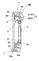
【解決手段】 波動歯車装置1は、剛性内歯車2、可撓性外歯車3および波動発生器4と、両歯車2、3を相対回転自在に支持しているクロスローラベアリング5とを有している。剛性内歯車2およびクロスローラベアリング5の内輪51として機能する円環状の複合部材6は、内輪51として機能する内輪形成部材61と、剛性内歯車2として機能する内歯形成部材62から構成され、ベアリング鋼からなる内輪形成部材61に、ダクタイル鋳物からなる内歯形成部材62が拡散接合により一体化されている。
【選択図】 図1
PROBLEM TO BE SOLVED: To provide a wave gear device having a bearing inner ring integrated internal gear having high rigidity and allowable moment load.
A wave gear device (1) includes a rigid internal gear (2), a flexible external gear (3), a wave generator (4), and a cross roller bearing (5) that supports both gears (2 and 3) so as to be relatively rotatable. ing. An annular composite member 6 that functions as the rigid inner gear 2 and the inner ring 51 of the cross roller bearing 5 includes an inner ring forming member 61 that functions as the inner ring 51 and an internal tooth forming member 62 that functions as the rigid internal gear 2. An inner tooth forming member 62 made of ductile cast is integrated with an inner ring forming member 61 made of bearing steel by diffusion bonding.
[Selection] Figure 1
Description
本発明は、環状の剛性内歯車に可撓性外歯車を部分的に噛み合わせ、これら両歯車の噛み合い位置を周方向に移動させることにより、両歯車の間に相対回転を発生させるように構成された波動歯車装置に関するものである。更に詳しくは、両歯車を相対回転自在の状態に支持している軸受の内輪に内歯車を一体化させた構成の波動歯車装置に関するものである。 In the present invention, a flexible external gear is partially meshed with an annular rigid internal gear, and the meshing position of both gears is moved in the circumferential direction so that relative rotation is generated between both gears. The present invention relates to a wave gear device. More specifically, the present invention relates to a wave gear device in which an internal gear is integrated with an inner ring of a bearing that supports both gears in a relatively rotatable state.
一般に知られている波動歯車装置は、環状の剛性内歯車と、この内側に配置された可撓性外歯車と、楕円形輪郭の波動発生器とを有している。波動発生器によって、可撓性外歯車は楕円形に撓められて剛性内歯車に部分的に噛み合っている。波動発生器をモータなどにより回転すると、両歯車の噛み合い位置が周方向に移動する。両歯車には2n枚(nは正の整数)、通常は2枚の歯数差があるので、噛み合い位置が周方向に移動すると、両歯車の間に相対回転が発生する。一方の歯車を固定しておくと、歯数差に対応した減速比で減速された減速回転出力が他方の歯車から出力される。 A generally known wave gear device has an annular rigid internal gear, a flexible external gear disposed on the inside thereof, and a wave generator having an elliptical profile. By the wave generator, the flexible external gear is bent into an ellipse and partially meshed with the rigid internal gear. When the wave generator is rotated by a motor or the like, the meshing position of both gears moves in the circumferential direction. Since both gears have a difference in the number of teeth of 2n (n is a positive integer), usually two, when the meshing position moves in the circumferential direction, relative rotation occurs between the two gears. If one of the gears is fixed, a reduced rotation output reduced by a reduction ratio corresponding to the difference in the number of teeth is output from the other gear.
この構成の波動歯車装置においては、両歯車を相対回転自在の状態に支持するためにクロスローラベアリングが用いられている。下記の特許文献1には、装置の小型化、軽量化を図るために、クロスローラベアリングの内輪の内周面に内歯を形成することにより、内輪と剛性内歯車を単一部材により形成した波動歯車装置が提案されている。
ここで、内輪と剛性内歯車を単一部材により形成する場合には、内歯の加工精度および耐磨耗性を考慮して、ダクタイル鋳物が用いられる。しかしながら、内輪軌道面および内歯が形成されたダクタイル鋳物からなる単一部材を用いて波動歯車装置を製造した場合には、そのモーメント剛性および許容モーメント荷重を確保できないことがある。 Here, when the inner ring and the rigid internal gear are formed by a single member, ductile casting is used in consideration of the processing accuracy and wear resistance of the inner teeth. However, when a wave gear device is manufactured using a single member made of a ductile casting in which the inner ring raceway surface and the inner teeth are formed, the moment stiffness and the allowable moment load may not be ensured.
本発明の課題は、この点に鑑みて、内歯の加工精度および耐磨耗性が高く、しかも、装置剛性および許容モーメント荷重も高い軸受内輪一体型の内歯車を備えた波動歯車装置を提案することにある。 In view of this point, the object of the present invention is to propose a wave gear device including an internal gear integrated with a bearing inner ring that has high processing accuracy and wear resistance of internal teeth, and also has high device rigidity and allowable moment load. There is to do.
上記の課題を解決するために、本発明の波動歯車装置は、
環状の剛性内歯車と、
環状の可撓性外歯車と、
前記可撓性外歯車を半径方向に撓めて前記剛性内歯車に部分的に噛み合わせ、これら両歯車の噛み合わせ位置を周方向に移動させる波動発生器と、
前記剛性内歯車および前記可撓性外歯車を相対回転自在の状態で支持している軸受とを有し、
前記軸受の外輪は前記可撓性外歯車に固定されており、
前記軸受の内輪は前記剛性内歯車が一体化された複合部材であり、
この複合部材は、円環状の内輪形成部材と、この内輪形成部材の外周面に形成した軌道面と、前記内輪形成部材の内周面に一体化された円環状の内歯形成部材と、この内歯形成部材の内周面に形成された内歯とを備えており、
前記内輪形成部材はベアリング鋼からなり、
前記内歯形成部材はダクタイル鋳物からなり、
前記内歯形成部材が拡散接合により前記内歯形成部材に一体化されていることを特徴としている。
In order to solve the above problems, the wave gear device of the present invention is:
An annular rigid internal gear;
An annular flexible external gear;
A wave generator that flexes the flexible external gear in the radial direction and partially meshes with the rigid internal gear, and moves the meshing position of both gears in the circumferential direction;
A bearing that supports the rigid internal gear and the flexible external gear in a relatively rotatable state;
An outer ring of the bearing is fixed to the flexible external gear;
The inner ring of the bearing is a composite member in which the rigid internal gear is integrated,
The composite member includes an annular inner ring forming member, a raceway surface formed on the outer peripheral surface of the inner ring forming member, an annular inner tooth forming member integrated on the inner peripheral surface of the inner ring forming member, An internal tooth formed on the inner peripheral surface of the internal tooth forming member,
The inner ring forming member is made of bearing steel,
The internal tooth forming member is made of ductile casting,
The internal tooth forming member is integrated with the internal tooth forming member by diffusion bonding.
ここで、前記軸受としては一般にクロスローラベアリングが用いられる。また、前記可撓性外歯車としては、シルクハット型の可撓性外歯車と呼ばれている形状のものを用いることができる。シルクハット型の可撓性外歯車は、円筒状の胴部と、この胴部の一端から半径方向の外方に広がっている環状のダイヤフラムと、前記ダイヤフラムの外周縁に連続して形成された円環状のボスと、前記胴部の外周面部分に形成した外歯とを備えている。この場合には、前記胴部の外側に前記軸受が同軸状態に配置され、前記外輪は、その円環状端面が前記ボスの円環状端面に当接した状態で、当該ボスに締結固定される。 Here, a cross roller bearing is generally used as the bearing. Further, as the flexible external gear, one having a shape called a top hat type flexible external gear can be used. The top hat type flexible external gear is formed continuously from a cylindrical body, an annular diaphragm extending radially outward from one end of the body, and an outer peripheral edge of the diaphragm. An annular boss and external teeth formed on the outer peripheral surface portion of the body portion are provided. In this case, the bearing is coaxially disposed outside the body portion, and the outer ring is fastened and fixed to the boss in a state where the annular end surface is in contact with the annular end surface of the boss.
以上説明したように、本発明の波動歯車装置では、その軸受内輪および内歯車として機能する複合部材が、ベアリング鋼からなる内輪形成部材に、ダクタイル鋳物からなる内歯形成部材を拡散接合により一体化した構成となっている。したがって、単一部材に内輪部分および内歯部分を形成した場合と同様に、装置の小型・軽量化を実現できる。同時に、精度良く耐摩耗性の高い内歯を形成できると共に、装置剛性および許容モーメント荷重も高めることができる。 As described above, in the wave gear device of the present invention, the composite member functioning as the bearing inner ring and the inner gear is integrated with the inner ring forming member made of bearing steel and the inner tooth forming member made of ductile casting by diffusion bonding. It has become the composition. Therefore, as in the case where the inner ring portion and the inner tooth portion are formed on a single member, the apparatus can be reduced in size and weight. At the same time, it is possible to form the internal teeth with high wear resistance with high accuracy, and to increase the apparatus rigidity and the allowable moment load.
以下に、図面を参照して、本発明を適用した波動歯車装置の実施の形態を説明する。 Embodiments of a wave gear device to which the present invention is applied will be described below with reference to the drawings.
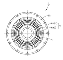
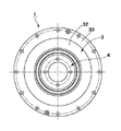
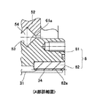
図1、2および3は、本発明によるシルクハット型の波動歯車装置を示す断面図、右側端面図および左側端面図である。また、図4はその部分拡大断面図である。これらの図に示すように、波動歯車装置1は、円環状の剛性内歯車2と、この内側に同軸状態に配置されたシルクハット形状の可撓性外歯車3と、この内側に嵌め込まれた楕円形輪郭の波動発生器4と、剛性内歯車2および可撓性外歯車3を相対回転自在の状態で支持しているクロスローラベアリング5とを備えている。
1, 2 and 3 are a sectional view, a right end view and a left end view showing a top hat type wave gear device according to the present invention. FIG. 4 is a partially enlarged sectional view thereof. As shown in these drawings, the wave gear device 1 is fitted into an annular rigid
シルクハット形状の可撓性外歯車3は、円筒状の胴部31と、この胴部31の一端から半径方向の外方に広がっている環状のダイヤフラム32と、ダイヤフラム32の外周縁に連続して形成された円環状のボス33と、胴部31の反対側の端部側の外周面部分に形成した外歯34とを備えている。可撓性外歯車3の胴部31は、当該胴部31とほぼ同一幅のクロスローラベアリング5によって同軸状態に取り囲まれている。
The top hat-shaped flexible
クロスローラベアリング5は、円環状の内輪51と、円環状の外輪52と、これらの間に形成されている矩形断面の円環状軌道53に転動自在の状態で交互に直交する状態で挿入されている複数個の円柱状のローラ54とを備えている。外輪52の円環状端面52aは、可撓性外歯車3のボス33の円環状端面33aに対応する大きさであり、これらの円環状端面52aおよび33aが相互に当接した状態で、締結用ボルト7によって双方の部材が締結固定されている。
The
ここで、本例の剛性内歯車2および内輪51は、円環状の複合部材6から構成されている。複合部材6は、内輪51として機能する円環状の内輪形成部材61と、この内輪形成部材61の内周面に一体化された剛性内歯車2として機能する円環状の内歯形成部材62から構成されている。内輪形成部材61の外周面には軌道面61aが形成されており、内歯形成部材62の内周面には内歯62aが形成されている。内輪形成部材61はベアリング鋼からなり、内歯形成部材62はダクタイル鋳物から形成されている。また、拡散接合により、内歯形成部材62が内歯形成部材61に一体化されている。
Here, the rigid
この構成の波動歯車装置1では、波動発生器4によって可撓性外歯車3の外歯34の形成部分が楕円状に撓められており、その楕円形の長軸方向の両端部分に位置する外歯34の部分が剛性内歯車2の内歯62aの部分に噛み合っている。例えば、剛性内歯車2(複合部材6)を固定し、モータ(図示せず)などによって波動発生器4を回転すると、両歯車2、3の噛み合い位置が円周方向に移動して、可撓性外歯車3から減速回転が出力される。
In the wave gear device 1 having this configuration, the portions where the
本例では、剛性内歯車2および内輪51が複合部材6から形成されているので、装置の小型化、軽量化を実現できる。また、剛性内歯車2は、複合部材6におけるダクタイル鋳物からなる内歯形成部材62によって形成されているので、内歯62aの加工精度および耐磨耗性が高い。さらに、内輪51は、複合部材6におけるベアリング鋼61からなる内輪形成部材61によって形成されているので、クロスローラベアリング5の剛性および許容モーメント荷重が高く、従って、装置1の剛性およびモーメント荷重も高い。
In this example, since the rigid
なお、本例では、両歯車2、3を相対回転自在に保持するための軸受としてクロスローラベアリング5を用いているが、ボールベアリングなどを用いることも可能である。
In this example, the cross roller bearing 5 is used as a bearing for holding the
1 波動歯車装置
2 剛性内歯車
3 可撓性外歯車
31 胴部
32 ダイヤフラム
33 ボス
33a 円環状端面
34 外歯
4 波動発生器
5 クロスローラベアリング
51 内輪
52 外輪
52a 円環状端面
54 ローラ
6 複合部材
61 内輪形成部材
61a 軌道面
62 内歯形成部材
62a 内歯
DESCRIPTION OF SYMBOLS 1
Claims (3)
環状の可撓性外歯車と、
前記可撓性外歯車を半径方向に撓めて前記剛性内歯車に部分的に噛み合わせ、これら両歯車の噛み合い位置を周方向に移動させる波動発生器と、
前記剛性内歯車および前記可撓性外歯車を相対回転自在の状態で支持している軸受とを有し、
前記軸受の外輪は前記可撓性外歯車に固定されており、
前記軸受の内輪は前記剛性内歯車が一体化された複合部材であり、
この複合部材は、円環状の内輪形成部材と、この内輪形成部材の外周面に形成された軌道面と、前記内輪形成部材の内周面に一体化された円環状の内歯形成部材と、この内歯形成部材の内周面に形成された内歯とを備えており、
前記内輪形成部材はベアリング鋼からなり、
前記内歯形成部材はダクタイル鋳物からなり、
前記内歯形成部材が拡散接合により前記内輪形成部材に一体化されている波動歯車装置。 An annular rigid internal gear;
An annular flexible external gear;
A wave generator that flexes the flexible external gear in the radial direction and partially meshes with the rigid internal gear, and moves the meshing position of both gears in the circumferential direction;
A bearing that supports the rigid internal gear and the flexible external gear in a relatively rotatable state;
An outer ring of the bearing is fixed to the flexible external gear;
The inner ring of the bearing is a composite member in which the rigid internal gear is integrated,
The composite member includes an annular inner ring forming member, a raceway surface formed on the outer peripheral surface of the inner ring forming member, an annular inner tooth forming member integrated with the inner peripheral surface of the inner ring forming member, An internal tooth formed on the inner peripheral surface of the internal tooth forming member,
The inner ring forming member is made of bearing steel,
The internal tooth forming member is made of ductile casting,
The wave gear device in which the inner tooth forming member is integrated with the inner ring forming member by diffusion bonding.
前記軸受はクロスローラベアリングである波動歯車装置。 In claim 1,
The wave gear device, wherein the bearing is a cross roller bearing.
前記可撓性外歯車は、円筒状の胴部と、この胴部の一端から半径方向の外方に広がっている環状のダイヤフラムと、前記ダイヤフラムの外周縁に連続して形成された円環状のボスと、前記胴部の外周面部分に形成した外歯とを備え、
前記胴部の外側に前記軸受が同軸状態に配置され、前記外輪はその円環状端面が前記ボスの円環状端面に当接した状態で、当該ボスに締結固定されている波動歯車装置。 In claim 2,
The flexible external gear includes a cylindrical body, an annular diaphragm extending radially outward from one end of the body, and an annular ring formed continuously on the outer periphery of the diaphragm. A boss, and external teeth formed on the outer peripheral surface portion of the body,
The wave gear device, wherein the bearing is coaxially disposed outside the body portion, and the outer ring is fastened and fixed to the boss in a state where the annular end surface is in contact with the annular end surface of the boss.
Priority Applications (4)
| Application Number | Priority Date | Filing Date | Title |
|---|---|---|---|
| JP2004102989A JP2005291237A (en) | 2004-03-31 | 2004-03-31 | Wave gear device having an internal gear integrated with a bearing inner ring |
| US11/063,823 US7165473B2 (en) | 2004-03-31 | 2005-02-23 | Wave gear device having internal gear integrally formed with inner ring of bearing |
| DE602005001131T DE602005001131T2 (en) | 2004-03-31 | 2005-03-30 | Voltage shaft gear with a rolling bearing raceway connected by diffusion bonding internal gear |
| EP05006894A EP1589261B1 (en) | 2004-03-31 | 2005-03-30 | Wave gear device having an internal gear which is diffusion bonded to an inner bearing ring |
Applications Claiming Priority (1)
| Application Number | Priority Date | Filing Date | Title |
|---|---|---|---|
| JP2004102989A JP2005291237A (en) | 2004-03-31 | 2004-03-31 | Wave gear device having an internal gear integrated with a bearing inner ring |
Publications (1)
| Publication Number | Publication Date |
|---|---|
| JP2005291237A true JP2005291237A (en) | 2005-10-20 |
Family
ID=34934583
Family Applications (1)
| Application Number | Title | Priority Date | Filing Date |
|---|---|---|---|
| JP2004102989A Pending JP2005291237A (en) | 2004-03-31 | 2004-03-31 | Wave gear device having an internal gear integrated with a bearing inner ring |
Country Status (4)
| Country | Link |
|---|---|
| US (1) | US7165473B2 (en) |
| EP (1) | EP1589261B1 (en) |
| JP (1) | JP2005291237A (en) |
| DE (1) | DE602005001131T2 (en) |
Cited By (7)
| Publication number | Priority date | Publication date | Assignee | Title |
|---|---|---|---|---|
| JP2009041623A (en) * | 2007-08-07 | 2009-02-26 | Sumitomo Heavy Ind Ltd | Oscillation inscribed planetary gear structure |
| KR101311413B1 (en) * | 2010-11-02 | 2013-09-25 | 주식회사 에스비비테크 | Strain wave gearing reducer |
| WO2019087316A1 (en) | 2017-10-31 | 2019-05-09 | 株式会社ハーモニック・ドライブ・システムズ | Wave gear device having unit structure |
| WO2020059081A1 (en) | 2018-09-20 | 2020-03-26 | 株式会社ハーモニック・ドライブ・システムズ | Unit type wave gear device |
| JP2022500612A (en) * | 2018-12-11 | 2022-01-04 | 愛磁科技(深セン)有限公司 | Deformation limitable wave reducer with two flexsplines |
| JPWO2022249355A1 (en) * | 2021-05-26 | 2022-12-01 | ||
| WO2022270670A1 (en) * | 2021-06-25 | 2022-12-29 | 주식회사 에스비비테크 | Strain wave gear device |
Families Citing this family (20)
| Publication number | Priority date | Publication date | Assignee | Title |
|---|---|---|---|---|
| DE112011105253T5 (en) * | 2011-05-16 | 2014-02-13 | Harmonic Drive Systems Inc. | Unit type wave gear |
| KR101748177B1 (en) * | 2011-07-29 | 2017-06-16 | 가부시키가이샤 하모닉 드라이브 시스템즈 | Wave gear device with composite roller bearing |
| DE112012000394T5 (en) * | 2012-12-12 | 2014-08-28 | Harmonic Drive Systems Inc. | Corrugated gear unit with input bearings |
| WO2014168545A1 (en) | 2013-04-09 | 2014-10-16 | Aktiebolaget Skf | Bearing component and its manufacturing method |
| SE537455C2 (en) * | 2013-04-09 | 2015-05-05 | Skf Ab | Process for obtaining a mechanical component by diffusion welding |
| US9768664B2 (en) | 2015-05-21 | 2017-09-19 | The Boeing Company | Balanced eccentric gear design and method |
| DE102016217055B4 (en) * | 2015-09-10 | 2023-08-24 | Schaeffler Technologies AG & Co. KG | Transmission with elastic gear |
| WO2017046927A1 (en) * | 2015-09-17 | 2017-03-23 | 株式会社ハーモニック・ドライブ・システムズ | Wave motion generator for wave motion gear device |
| US10203022B2 (en) | 2015-11-04 | 2019-02-12 | The Boeing Company | Elliptically interfacing wobble motion gearing system and method |
| US10024391B2 (en) | 2016-01-06 | 2018-07-17 | The Boeing Company | Elliptically interfacing gearbox |
| US10574109B2 (en) | 2016-04-28 | 2020-02-25 | The Boeing Company | Permanent magnet biased virtual elliptical motor |
| US10215244B2 (en) | 2017-03-02 | 2019-02-26 | The Boeing Company | Elliptically interfacing gear assisted braking system |
| US10520063B2 (en) | 2017-04-21 | 2019-12-31 | The Boeing Company | Mechanical virtual elliptical drive |
| US10267383B2 (en) | 2017-05-03 | 2019-04-23 | The Boeing Company | Self-aligning virtual elliptical drive |
| CN111288077A (en) * | 2018-12-10 | 2020-06-16 | 镁亚精密股份有限公司 | reduction drive bearing |
| US10968969B2 (en) | 2019-03-18 | 2021-04-06 | The Boeing Company | Nutational braking systems and methods |
| US11459098B2 (en) | 2019-11-27 | 2022-10-04 | The Boeing Company | Variable speed transmission and related methods |
| JP7419193B2 (en) * | 2020-08-27 | 2024-01-22 | 住友重機械工業株式会社 | Flexible mesh gear system |
| CN112855761A (en) * | 2021-02-09 | 2021-05-28 | 中山早稻田科技有限公司 | Crossed roller bearing with toothed inner ring |
| CN113623365A (en) * | 2021-08-16 | 2021-11-09 | 浙江环动机器人关节科技有限公司 | An ultra-flat three-wave harmonic reducer |
Family Cites Families (5)
| Publication number | Priority date | Publication date | Assignee | Title |
|---|---|---|---|---|
| US3147640A (en) * | 1960-04-13 | 1964-09-08 | United Shoe Machinery Corp | Wave generator for wave converter |
| EP0945650B1 (en) * | 1996-04-19 | 2005-02-02 | Harmonic Drive Systems Inc. | Silk hat flexible engagement gear device |
| JPH09291983A (en) | 1996-04-30 | 1997-11-11 | Harmonic Drive Syst Ind Co Ltd | Mounting structure of flexible external gear of top hat type flexural mesh type gear device |
| JP2002307237A (en) * | 2001-04-09 | 2002-10-23 | Harmonic Drive Syst Ind Co Ltd | Method of manufacturing rigid internal gear of wave gear device |
| JP4390124B2 (en) | 2001-05-22 | 2009-12-24 | 株式会社ハーモニック・ドライブ・システムズ | Lightweight bearing manufacturing method |
-
2004
- 2004-03-31 JP JP2004102989A patent/JP2005291237A/en active Pending
-
2005
- 2005-02-23 US US11/063,823 patent/US7165473B2/en not_active Expired - Lifetime
- 2005-03-30 EP EP05006894A patent/EP1589261B1/en not_active Expired - Lifetime
- 2005-03-30 DE DE602005001131T patent/DE602005001131T2/en not_active Expired - Lifetime
Cited By (17)
| Publication number | Priority date | Publication date | Assignee | Title |
|---|---|---|---|---|
| JP2009041623A (en) * | 2007-08-07 | 2009-02-26 | Sumitomo Heavy Ind Ltd | Oscillation inscribed planetary gear structure |
| KR101311413B1 (en) * | 2010-11-02 | 2013-09-25 | 주식회사 에스비비테크 | Strain wave gearing reducer |
| US11320034B2 (en) | 2017-10-31 | 2022-05-03 | Harmonic Drive Systems Inc. | Strain wave gearing having unit structure |
| WO2019087316A1 (en) | 2017-10-31 | 2019-05-09 | 株式会社ハーモニック・ドライブ・システムズ | Wave gear device having unit structure |
| KR20200047718A (en) | 2017-10-31 | 2020-05-07 | 가부시키가이샤 하모닉 드라이브 시스템즈 | Unit structure wave gear device |
| KR20200053608A (en) | 2018-09-20 | 2020-05-18 | 가부시키가이샤 하모닉 드라이브 시스템즈 | Unit type wave gear device |
| US11168775B2 (en) | 2018-09-20 | 2021-11-09 | Harmonic Drive Systems Inc. | Unit-type strain wave gearing |
| WO2020059081A1 (en) | 2018-09-20 | 2020-03-26 | 株式会社ハーモニック・ドライブ・システムズ | Unit type wave gear device |
| JP7081753B2 (en) | 2018-12-11 | 2022-06-07 | 愛磁科技(寧波)有限公司 | Deformation limitable wave reducer with two flexsplines |
| JP2022500612A (en) * | 2018-12-11 | 2022-01-04 | 愛磁科技(深セン)有限公司 | Deformation limitable wave reducer with two flexsplines |
| JPWO2022249355A1 (en) * | 2021-05-26 | 2022-12-01 | ||
| WO2022249355A1 (en) * | 2021-05-26 | 2022-12-01 | 株式会社ハーモニック・ドライブ・システムズ | Strain wave gear device |
| CN117280135A (en) * | 2021-05-26 | 2023-12-22 | 谐波传动系统有限公司 | Wave gear device |
| JP7494394B2 (en) | 2021-05-26 | 2024-06-03 | 株式会社ハーモニック・ドライブ・システムズ | Strain Wave Gearing |
| US12234902B2 (en) | 2021-05-26 | 2025-02-25 | Harmonic Drive Systems Inc. | Strain wave gearing |
| TWI890921B (en) * | 2021-05-26 | 2025-07-21 | 日商和諧驅動系統股份有限公司 | Strain wave gearing |
| WO2022270670A1 (en) * | 2021-06-25 | 2022-12-29 | 주식회사 에스비비테크 | Strain wave gear device |
Also Published As
| Publication number | Publication date |
|---|---|
| DE602005001131T2 (en) | 2008-01-17 |
| DE602005001131D1 (en) | 2007-06-28 |
| EP1589261B1 (en) | 2007-05-16 |
| US20050217420A1 (en) | 2005-10-06 |
| US7165473B2 (en) | 2007-01-23 |
| EP1589261A1 (en) | 2005-10-26 |
Similar Documents
| Publication | Publication Date | Title |
|---|---|---|
| JP2005291237A (en) | Wave gear device having an internal gear integrated with a bearing inner ring | |
| JP6067112B2 (en) | Hollow wave gear device | |
| JP5940066B2 (en) | Wave gear device with compound rolling bearing | |
| JP5335152B1 (en) | Wave generator of wave gear device | |
| JP5312364B2 (en) | Bending gear system | |
| JP5496426B1 (en) | Wave gear unit with input bearing | |
| JP5968545B2 (en) | Wave gear device, friction engagement type wave device, and wave generator | |
| US20120085188A1 (en) | Noncircular bearing, wave generator, and wave gear device | |
| JPH08312730A (en) | Flat type wave gear device | |
| JP7450776B2 (en) | gear system | |
| JP2009299765A (en) | Flexible meshing-type gear device | |
| WO2009093556A1 (en) | Power transmission device with bevel gear | |
| JP2007016838A (en) | Top hat wave gear device | |
| JP6552745B2 (en) | Wave generator and wave gear device | |
| JP5771081B2 (en) | Bending gear system | |
| JP5939955B2 (en) | Gear device | |
| JP2008025687A (en) | Bearing for wave gear device | |
| JP2011231831A (en) | Cage for radial needle bearing, and radial needle bearing | |
| JPH09303497A (en) | Top hat type flexible meshing gear unit | |
| JP7494394B2 (en) | Strain Wave Gearing | |
| JP2014190519A (en) | Reduction gear | |
| JP6173232B2 (en) | Flexure meshing gear device and method for correcting tooth profile of flexure meshing gear device | |
| JP2512462Y2 (en) | Harmonic gear transmission wave generator | |
| JP2023070076A (en) | Wave motion generator for strain wave gear reducer, and strain wave gear reducer | |
| JPH04109246U (en) | Oldham type wave generator of harmonic transmission |
Legal Events
| Date | Code | Title | Description |
|---|---|---|---|
| A621 | Written request for application examination |
Free format text: JAPANESE INTERMEDIATE CODE: A621 Effective date: 20061115 |
|
| A977 | Report on retrieval |
Free format text: JAPANESE INTERMEDIATE CODE: A971007 Effective date: 20090515 |
|
| A131 | Notification of reasons for refusal |
Free format text: JAPANESE INTERMEDIATE CODE: A131 Effective date: 20090519 |
|
| A02 | Decision of refusal |
Free format text: JAPANESE INTERMEDIATE CODE: A02 Effective date: 20090929 |