EP3399151A1 - Verschleissschutzblech für eine laufschaufel einer gasturbine - Google Patents
Verschleissschutzblech für eine laufschaufel einer gasturbine Download PDFInfo
- Publication number
- EP3399151A1 EP3399151A1 EP18162095.6A EP18162095A EP3399151A1 EP 3399151 A1 EP3399151 A1 EP 3399151A1 EP 18162095 A EP18162095 A EP 18162095A EP 3399151 A1 EP3399151 A1 EP 3399151A1
- Authority
- EP
- European Patent Office
- Prior art keywords
- axial
- blade root
- base
- rotor
- securing
- Prior art date
- Legal status (The legal status is an assumption and is not a legal conclusion. Google has not performed a legal analysis and makes no representation as to the accuracy of the status listed.)
- Granted
Links
Images

Classifications
-
- F—MECHANICAL ENGINEERING; LIGHTING; HEATING; WEAPONS; BLASTING
- F01—MACHINES OR ENGINES IN GENERAL; ENGINE PLANTS IN GENERAL; STEAM ENGINES
- F01D—NON-POSITIVE DISPLACEMENT MACHINES OR ENGINES, e.g. STEAM TURBINES
- F01D5/00—Blades; Blade-carrying members; Heating, heat-insulating, cooling or antivibration means on the blades or the members
- F01D5/30—Fixing blades to rotors; Blade roots ; Blade spacers
- F01D5/3092—Protective layers between blade root and rotor disc surfaces, e.g. anti-friction layers
-
- F—MECHANICAL ENGINEERING; LIGHTING; HEATING; WEAPONS; BLASTING
- F04—POSITIVE - DISPLACEMENT MACHINES FOR LIQUIDS; PUMPS FOR LIQUIDS OR ELASTIC FLUIDS
- F04D—NON-POSITIVE-DISPLACEMENT PUMPS
- F04D29/00—Details, component parts, or accessories
- F04D29/26—Rotors specially for elastic fluids
- F04D29/32—Rotors specially for elastic fluids for axial flow pumps
- F04D29/321—Rotors specially for elastic fluids for axial flow pumps for axial flow compressors
- F04D29/322—Blade mountings
-
- F—MECHANICAL ENGINEERING; LIGHTING; HEATING; WEAPONS; BLASTING
- F04—POSITIVE - DISPLACEMENT MACHINES FOR LIQUIDS; PUMPS FOR LIQUIDS OR ELASTIC FLUIDS
- F04D—NON-POSITIVE-DISPLACEMENT PUMPS
- F04D29/00—Details, component parts, or accessories
- F04D29/26—Rotors specially for elastic fluids
- F04D29/32—Rotors specially for elastic fluids for axial flow pumps
- F04D29/321—Rotors specially for elastic fluids for axial flow pumps for axial flow compressors
- F04D29/324—Blades
-
- F—MECHANICAL ENGINEERING; LIGHTING; HEATING; WEAPONS; BLASTING
- F01—MACHINES OR ENGINES IN GENERAL; ENGINE PLANTS IN GENERAL; STEAM ENGINES
- F01D—NON-POSITIVE DISPLACEMENT MACHINES OR ENGINES, e.g. STEAM TURBINES
- F01D5/00—Blades; Blade-carrying members; Heating, heat-insulating, cooling or antivibration means on the blades or the members
- F01D5/30—Fixing blades to rotors; Blade roots ; Blade spacers
- F01D5/3007—Fixing blades to rotors; Blade roots ; Blade spacers of axial insertion type
-
- F—MECHANICAL ENGINEERING; LIGHTING; HEATING; WEAPONS; BLASTING
- F05—INDEXING SCHEMES RELATING TO ENGINES OR PUMPS IN VARIOUS SUBCLASSES OF CLASSES F01-F04
- F05D—INDEXING SCHEME FOR ASPECTS RELATING TO NON-POSITIVE-DISPLACEMENT MACHINES OR ENGINES, GAS-TURBINES OR JET-PROPULSION PLANTS
- F05D2220/00—Application
- F05D2220/30—Application in turbines
- F05D2220/32—Application in turbines in gas turbines
- F05D2220/323—Application in turbines in gas turbines for aircraft propulsion, e.g. jet engines
-
- F—MECHANICAL ENGINEERING; LIGHTING; HEATING; WEAPONS; BLASTING
- F05—INDEXING SCHEMES RELATING TO ENGINES OR PUMPS IN VARIOUS SUBCLASSES OF CLASSES F01-F04
- F05D—INDEXING SCHEME FOR ASPECTS RELATING TO NON-POSITIVE-DISPLACEMENT MACHINES OR ENGINES, GAS-TURBINES OR JET-PROPULSION PLANTS
- F05D2230/00—Manufacture
- F05D2230/50—Building or constructing in particular ways
- F05D2230/54—Building or constructing in particular ways by sheet metal manufacturing
-
- F—MECHANICAL ENGINEERING; LIGHTING; HEATING; WEAPONS; BLASTING
- F05—INDEXING SCHEMES RELATING TO ENGINES OR PUMPS IN VARIOUS SUBCLASSES OF CLASSES F01-F04
- F05D—INDEXING SCHEME FOR ASPECTS RELATING TO NON-POSITIVE-DISPLACEMENT MACHINES OR ENGINES, GAS-TURBINES OR JET-PROPULSION PLANTS
- F05D2240/00—Components
- F05D2240/20—Rotors
- F05D2240/24—Rotors for turbines
-
- F—MECHANICAL ENGINEERING; LIGHTING; HEATING; WEAPONS; BLASTING
- F05—INDEXING SCHEMES RELATING TO ENGINES OR PUMPS IN VARIOUS SUBCLASSES OF CLASSES F01-F04
- F05D—INDEXING SCHEME FOR ASPECTS RELATING TO NON-POSITIVE-DISPLACEMENT MACHINES OR ENGINES, GAS-TURBINES OR JET-PROPULSION PLANTS
- F05D2250/00—Geometry
- F05D2250/70—Shape
- F05D2250/71—Shape curved
- F05D2250/711—Shape curved convex
-
- F—MECHANICAL ENGINEERING; LIGHTING; HEATING; WEAPONS; BLASTING
- F05—INDEXING SCHEMES RELATING TO ENGINES OR PUMPS IN VARIOUS SUBCLASSES OF CLASSES F01-F04
- F05D—INDEXING SCHEME FOR ASPECTS RELATING TO NON-POSITIVE-DISPLACEMENT MACHINES OR ENGINES, GAS-TURBINES OR JET-PROPULSION PLANTS
- F05D2260/00—Function
- F05D2260/30—Retaining components in desired mutual position
Definitions
- the present invention relates to a wear apron for a blade root of a blade of a gas turbine, in particular aircraft gas turbine, with a base and two base connected to the side walls, wherein the side walls are opposite and are shaped so that they substantially to an outer contour of a respective blade root are formed complementary, and wherein the wear guard is adapted to be received in an installed state between the respective blade root and a blade root receiving a rotor, in particular between the respective blade root and arranged in the blade root receiving axial securing element.
- the provision of a wear guard between a blade root and a blade root receiving a rotor is known per se.
- the wear guard plate is used in particular to avoid wear on the blade root and on the blade root receiving, so that after a certain period of the gas turbine usually only the wear plates must be replaced.
- WO2016059338A1 is a wear protection film for a compressor blade is known, which is placed in the circumferential direction on a blade root and protrudes in the mounted state both in the circumferential direction and in the axial direction over the blade root.
- the object of the invention is to provide a wear guard in which the installation is improved, so that damage to the wear guard can be prevented.
- the sidewalls protrude at least one of their axial ends with a respective side end portion over an axial end portion of the base, and a guide portion adjoins the axial end portion of the base, starting from the base in the direction of axial side end portion of the side walls is bent.
- the guide section facilitates insertion into the blade foot receptacle.
- the side walls at least one of its axial ends, preferably the one with the bent guide portion projecting with a respective side end portion of an axial end portion of the base, also an axial protrusion of the wear guard plate on the rotor disk and / or in a groove, in particular Axial groove, the rotor disc recorded blade foot can be prevented.
- the wear guard can be completely disposed within the disc groove and at the same time the blade end on one or both sides axially flush with the rotor disc, without the wear guard also only partially over the blade root and / or over the rotor disc.
- the guide section be bent in such a way that it has substantially the same curvature as a blade root area which comes into contact or is in contact with the guide section.
- the guide portion may have a projected length corresponding to about 0.75 to 1.0 times a radius with respect to a projection in the axial direction the guide section is bent. As a result, the guide portion does not protrude beyond the axial ends of the side end portions in the axial direction.
- the guide portion may be disposed on an axial insertion end of the blade root, such that the wear guard plate and the associated blade root in the axial insertion direction are displaceable relative to the relevant rotor blade root receptacle of the rotor.
- the wear guard plate is taken during insertion of the blade from the blade root.
- the guide portion acts as a kind of tab, which rests on the blade root, so that the entire wear guard can be moved when the blade root is inserted in the axial direction.
- the guide portion is particularly adapted to act during installation of the blade in the rotor. When removing a blade from the rotor of the guide section has no effect and the blade root can be moved separately from the wear plate in the axial direction of removal.
- a rotor for a gas turbine in particular aircraft gas turbine, with a rotor body, in particular a blade disc, in which at least one blade root receptacle is formed, in which a blade root of an associated blade is arranged and secured by an axial securing element, and with a wear guard having a base and two side walls joined to the base, the side walls being circumferentially opposed and shaped to be substantially complementary to an outer contour of the blade root, and wherein the wear guard is configured to be in one installed state between the respective blade root and the axial securing element, wherein it is proposed that the side walls of the wear plate at least one of its axial ends with a respective Se That is, the end portion projecting beyond an axial end portion of the base and that adjoins the axial end portion of the base, a guide portion which is bent from the base in the direction of the axial side end portions of the side walls, in particular in the radial direction bent outward.
- the axial securing element may comprise a first securing portion and a second securing portion, which are interconnected by a securing base, wherein the first securing portion is formed such that it forms a first stop for the Forming blade root in the axial direction, wherein the first securing portion and the securing base are interconnected by a curved portion, and wherein the guide portion is disposed in the region of the curvature portion between the blade root and the axial securing element.
- the first securing portion and the securing base are aligned substantially orthogonal to each other, so that the curvature portion has an arc length substantially equal to ⁇ / 2 rad, wherein the arc length of the guide portion of the wear guard plate smaller than ⁇ / 2 rad and greater than or equal to ⁇ / 4 rad.
- the second securing portion of the axial securing element may be formed such that it forms a second stop for the axial securing element on the rotor base body.
- the axial securing element in the axial direction of installation can be inserted up to the second stop in the blade foot receptacle.
- the first securing portion may extend radially outward and the second securing portion may extend radially inward.
- the invention further relates to a gas turbine, in particular aircraft gas turbine with at least one rotor described above.
- the rotor may be assigned to the compressor or the turbine, in particular a high-speed turbine or low-pressure turbine.
- High-speed means that the turbine is coupled to the fan via a gearbox and rotates faster than the fan during operation.
- Low pressure means that there is at least one additional turbine downstream of the combustion chamber, which is located upstream of the low-pressure turbine.
- Fig. 1 shows in a schematic and highly simplified sectional view in the plane defined by the radial direction RR and circumferential direction UR cutting plane a blade root 10 of a blade otherwise not shown.
- the blade root 10 is received in a blade foot receptacle 12 of a rotor 14.
- the rotor 14 may be formed as a rotor disk and along its outer periphery a plurality of blade root receivers 12 may be formed, so that an entire blade ring for the gas turbine can be provided.
- the blade root 10 has an outer contour 16, which is arranged in an inner contour 18 of the blade foot receptacle.
- the outer contour 16 and the inner contour 18 are formed substantially complementary to each other.
- the blade root 10 is inserted into the blade root receiver 12 in the axial direction AR (substantially orthogonal to the cutting plane of the Fig. 1 ) or taken out of this.
- the axial direction AR corresponds to the direction of the rotor axis of rotation.
- the illustrated shapes of the outer contour 16 and the inner contour 18 are purely qualitative. In particular, illustrated distances or gaps between these two contours 16, 18 can also be designed differently, for example, smaller than shown.
- a wear apron 20 may be disposed between the blade root 10 and the blade receiving 12.
- Fig. 1 is such a wear guard 20 indicated by a dashed line purely qualitatively. It should be noted that the dashed line is not to be understood so that the wear plate 20 is a component with interruptions. Rather, the wear guard has based on the sectional view of Fig. 1 usually an uninterrupted volume of material.
- the wear protection plate 20 has a shape that is formed substantially complementary to the blade root 10, in particular complementary to a radially inwardly disposed portion of the blade root 10. From the schematic sectional view of Fig. 1 It can also be seen that the wear guard plate 20 is generally not formed along an entire radial height of the blade root 10.
- Fig. 2 shows in a simplified and schematic perspective view of an embodiment of a wear protection plate 20.
- the wear plate comprises a base 22 and two side walls 24a, 24b.
- the base 22 and the side walls 24a, 24b may be integrally formed with each other.
- the wear protection plate 20 may in particular be formed from a single machined, for example stamped and bent, metal piece.
- the side walls 24a, 24b are formed or have an outer shape which is adapted to an outer contour of a blade root, not shown here. Purely schematic is in this respect again on the Fig. 1 in which the side walls 24a, 24b and the base 22 are also designated for the sake of completeness, even if the Fig. 1 not exactly the embodiment of Fig. 2 shows.
- the base 22 extends substantially in the axial direction AR and in the circumferential direction UR.
- the base 22 is formed as an area in the plane defined by the axial direction AR and the circumferential direction UR (or a tangential direction to the circumferential direction).
- the base 22 does not necessarily have to be a flat surface, it may also partially or in total have a curvature, for example it may have a radially inwardly convex shape.
- a guide portion 28 is arranged.
- the guide portion 28 may also be formed integrally with the base 22.
- the guide portion 28 has a bent or curved shape. The curvature is concave on the blade side facing the blade.
- the guide section 28 is in the direction of the side walls 24a, 24b, in particular bent in the direction of the side end portions 30a, 30b. Based on an installation position on a rotor, the guide section 28 is bent radially outward.
- the side end portions 30 a, 30 b protrude in the axial direction AR beyond the end portion 26 of the base 22.
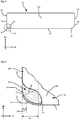
- Fig. 3 which shows a lateral plan view of the side wall 24b.
- the guide portion 28 can be seen. Since the side end portions 30a, 30b protrude beyond the base 22 in the axial direction, it is possible to deform, particularly bend, the guide portion 28, which also forms a kind of free end of the base 20. From the Fig. 3 It can also be seen that the guide section 28 is provided in the embodiment only at one axial end of the wear guard plate 20. This axial end may also be referred to as insertion end 32. The opposite axial end may be referred to as a performer 34 of the wear guard plate 20.
- Fig. 4 is an enlarged view of the guide portion 28 can be seen approximately corresponding to the in Fig. 3 marked IV area.
- the blade foot 10 is indicated by hatching.
- the guide portion 28 is bent so that its inner radius IR substantially corresponds to an outer radius of the blade root 10 in this area.
- the blade root 10 rests directly on the guide section 28 of the wear protection plate 20 in the manner of a positive connection.
- the length of the guide section 28 is in a range which is greater than or equal to 75% of the inner radius IR but smaller than the inner radius IR or equal to the inner radius IR.
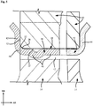
- Fig. 5 shows a sectional view of the blade root 10, which is arranged or installed in the blade foot receptacle 12 of the rotor 14. Between the blade foot 12 and the blade root 10, the wear plate 20 is arranged. Furthermore, an axial securing element 40 is shown in this example. The axial securing element 40 is arranged between the wear protection plate 20 and the blade foot receptacle 12. The axial securing element 40 may also be referred to as an axial securing plate. It comprises a first securing section 42, which is set up to serve as the first axial stop or axial contact surface for the blade root 10. The first securing portion 42 is bent radially outward.
- the axial securing element 40 further comprises a second securing portion 44, which serves in particular to form a second axial stop on the rotor 14.
- the second securing portion 44 is bent radially outward. It should be noted that the second securing portion 44 in the Fig. 5 is illustrated for purposes of clarity, without it being understood that the second securing portion 44 must have exactly the shape shown. Rather, other embodiments of the second securing portion 44 are conceivable.
- the axial securing member 40 further includes a securing base 46 extending between the first securing portion 42 and the second securing portion 44, substantially along the axial direction AR.
- the first securing portion 42 is substantially orthogonal to the securing base 46, in particular it extends substantially in the radial direction RR.
- a transition between the first securing portion 42 and the securing base 46 is formed by a curved portion 48.
- the curvature portion 48 has an arc length substantially equal to ⁇ / 2 rad.
- the guide portion 28 of the wear guard plate is arranged or received.
- the arc length of the guide section 28 of the wear protection plate 20 is less than ⁇ / 2 rad and greater than or equal to ⁇ / 4 rad.
- the guide portion 28 is so dimensioned or bent or curved that its free end 52 does not project beyond the axial end 32 of the blade root 10. This will ensure that the Guide portion 28 of the wear plate 20 is not arranged or clamped in the region extending substantially in the radial direction RR between the first securing portion 42 and the blade root 10. Furthermore, it can be seen that the guide section 28 is dimensioned or curved or curved in such a way that a sufficient positive locking is ensured with the blade root 10 so that the wear protection plate 20, if appropriate with the blade root 10, is inserted when the blade root 10 is inserted into the blade root receptacle 12 in the axial direction until his in the Fig. 5 shown end position is moved, in particular relative to the axial securing element 40 is moved.
- the insertion direction runs from right to left.
- the guide section 28 therefore serves, in particular, to ensure that the wear protection plate 20 can be automatically brought into a desired or correct position relative to the blade foot receptacle 12 or the axial securing element 40 when the blade root 10 is inserted. Accordingly, it can be prevented that the position of the wear protection plate 20 after insertion of the blade root 10 must be corrected, whereby the risk of damage to the wear plate 20 can be minimized and possibly even excluded.
Landscapes
- Engineering & Computer Science (AREA)
- Mechanical Engineering (AREA)
- General Engineering & Computer Science (AREA)
- Turbine Rotor Nozzle Sealing (AREA)
- Structures Of Non-Positive Displacement Pumps (AREA)
Abstract
Description
- Die vorliegende Erfindung betrifft ein Verschleiß schutzblech für einen Laufschaufelfuß einer Laufschaufel einer Gasturbine, insbesondere Fluggasturbine, mit einer Basis und zwei mit der Basis verbundenen Seitenwandungen, wobei die Seitenwandungen sich gegenüber liegen und so geformt sind, dass sie im Wesentlichen zu einer Außenkontur eines betreffenden Laufschaufelfußes komplementär ausgebildet sind, und wobei das Verschleißschutzblech dazu eingerichtet ist, in einem eingebauten Zustand zwischen dem betreffenden Laufschaufelfuß und einer Laufschaufelfußaufnahme eines Rotors, insbesondere zwischen dem betreffenden Laufschaufelfuß und einem in der Laufschaufelfußaufnahme angeordneten Axialsicherungselement aufgenommen zu sein.
- Richtungsangaben wie "Axial-" bzw. "axial", "Radial-" bzw. "radial" und "Umfangs-" sind grundsätzlich auf die Maschinenachse der Gasturbine bezogen zu verstehen, sofern sich aus dem Kontext nicht explizit oder implizit etwas anderes ergibt.
- Das Vorsehen eines Verschleißschutzblechs zwischen einem Laufschaufelfuß und einer Laufschaufelfußaufnahme eines Rotors ist an sich bekannt. Das Verschleißschutzblech dient insbesondere dazu, den Verschleiß am Laufschaufelfuß und an der Laufschaufelfußaufnahme zu vermeiden, so dass nach einer bestimmten Laufzeit der Gasturbine in der Regel nur die Verschleißschutzbleche ausgetauscht werden müssen.
- Es hat sich allerdings gezeigt, dass Verschleißschutzbleche beim Einbau oft verrutschen, so dass ein unerwünschter Überstand zwischen dem Rotor (Rotorscheibe) und einer betreffenden Laufschaufel entstehen kann. Entsprechend ist es erforderlich, dass verrutschte Verschleißschutzbleche nachgerichtet werden, wobei es aber regelmäßig zu Beschädigungen an den Verschleißschutzblechen kommen kann. Dies kann im ungünstigsten Fall dazu führen, dass ein gesamter Laufschaufelkranz ausgebaut und alle Verschleißschutzbleche erneuert werden müssen.
- Aus der
WO2016059338A1 ist eine Verschleißschutzfolie für eine Verdichterschaufel bekannt, die in Umfangsrichtung auf einen Schaufelfuß aufgesetzt wird und die im aufgesetzten Zustand sowohl in Umfangsrichtung als auch in Axialrichtung über den Schaufelfuß vorsteht. - Aufgabe der Erfindung ist es, ein Verschleißschutzblech bereitzustellen, bei dem der Einbau verbessert ist, so dass Beschädigungen am Verschleißschutzblech verhindert werden können.
- Zur Lösung dieser Aufgabe wird vorgeschlagen, dass beim Verschleißschutzblech die Seitenwandungen an wenigsten einem ihrer axialen Enden mit einem jeweiligen Seitenendabschnitt über einen axialen Endbereich der Basis vorstehen und dass sich an den axialen Endbereich der Basis ein Führungsabschnitt anschließt, der ausgehend von der Basis in Richtung der axialen Seitenendabschnitt der Seitenwandungen gebogen ist.
- Der Führungsabschnitt erleichtert aufgrund seiner gebogenen Form das Einführen in die Laufschaufelfußaufnahme.
- Ein Verrutschen kann dadurch verhindert werden.
- Dadurch, dass die Seitenwandungen an wenigsten einem ihrer axialen Enden, vorzugsweise demjenigen mit dem gebogen Führungsabschnitt, mit einem jeweiligen Seitenendabschnitt über einen axialen Endbereich der Basis vorstehen, kann zudem ein axiales Überstehen des Verschleißschutzbleches über die Rotorscheibe und/oder den in einer Nut, insbesondere Axialnut, der Rotorscheibe aufgenommenen Laufschaufelfuß verhindert werden. Mit anderen Worten, kann das Verschleißschutzblech vollständig innerhalb der Scheibennut angeordnet sein und dabei gleichzeitig der Laufschaufelfuß ein- oder beidseitig axial bündig mit der Rotorscheibe abschließen, ohne dass das Verschleißschutzblech auch nur abschnittweise über den Laufschaufelfuß und/oder über die Rotorscheibe übersteht.
- Weiterbildend wird vorgeschlagen, dass der Führungsabschnitt derart gebogen ist, dass er im Wesentlichen die gleiche Krümmung aufweist wie ein mit dem Führungsabschnitt in Kontakt kommender oder in Kontakt stehender Laufschaufelfußbereich.
- Hierdurch wird zwischen dem Führungsabschnitt und dem Laufschaufelfuß ein Bereich einer formschlüssigen Anlage bzw. einer Formschlussverbindung hergestellt.
- Der Führungsabschnitt kann bezogen auf eine Projektion auf die Axialrichtung eine projizierte Länge aufweisen, die etwa dem 0,75 bis 1,0-Fachen eines Radius entspricht, mit dem der Führungsabschnitt gebogen ist. Hierdurch steht der Führungsabschnitt in Axialrichtung nicht über die axialen Enden der Seitenendabschnitte vor.
- Ferner kann der Führungsabschnitt an einem axialen Einführende des Laufschaufelfußes angeordnet sein, derart, dass das Verschleißschutzblech und der zugeordnete Laufschaufelfuß in axialer Einführrichtung gemeinsam verschiebbar sind relativ zu der betreffenden Laufschaufelfußaufnahme des Rotors. Durch die oben bereits erwähnte Formschlussverbindung bzw. formschlüssige Anlage aneinander wird das Verschleißschutzblech beim Einführen der Laufschaufel vom Laufschaufelfuß mitgenommen. Dabei wirkt der Führungsabschnitt als eine Art Lasche, die am Laufschaufelfuß anliegt, so dass das gesamte Verschleißschutzblech mitbewegt werden kann, wenn der Laufschaufelfuß in Axialrichtung eingeführt wird. Es wird darauf hingewiesen, dass der Führungsabschnitt insbesondere dazu eingerichtet ist, beim Einbau der Laufschaufel in den Rotor zu wirken. Beim Ausbau einer Laufschaufel aus dem Rotor hat der Führungsabschnitt keine Wirkung und der Laufschaufelfuß kann gesondert vom Verschleißschutzblech in axialer Ausbaurichtung bewegt werden.
- Die oben genannte Aufgabe wir ferner gelöst durch einen Rotor für ein Gasturbine, insbesondere Fluggasturbine, mit einem Rotorgrundkörper, insbesondere einer Laufschaufelscheibe, in dem wenigstens eine Laufschaufelfußaufnahme ausgebildet ist, in die ein Laufschaufelfuß einer zugeordneten Laufschaufel angeordnet ist und mittels eines Axialsicherungselements gesichert ist, und mit einem Verschleißschutzblech mit einer Basis und zwei mit der Basis verbundenen Seitenwandungen, wobei die Seitenwandungen in Umfangsrichtung sich gegenüber liegen und so geformt sind, dass sie im Wesentlichen zu einer Außenkontur des Laufschaufelfußes komplementär ausgebildet sind, und wobei das Verschleißschutzblech dazu eingerichtet ist, in einem eingebauten Zustand zwischen dem betreffenden Laufschaufelfuß und dem Axialsicherungselement aufgenommen zu sein, wobei vorgeschlagen wird, dass die Seitenwandungen des Verschleißschutzblechs an wenigsten einem ihrer axialen Enden mit einem jeweiligen Seitenendabschnitt über einen axialen Endbereich der Basis vorstehen und dass sich an den axialen Endbereich der Basis ein Führungsabschnitt anschließt, der ausgehend von der Basis in Richtung der axialen Seitenendabschnitte der Seitenwandungen gebogen ist, insbesondere in Radialrichtung nach außen gebogen ist.
- Das Axialsicherungselement kann einen ersten Sicherungsabschnitt und einen zweiten Sicherungsabschnitt aufweisen, die durch eine Sicherungsbasis miteinander verbunden sind, wobei der erste Sicherungsabschnitt derart ausgebildet ist, dass er einen ersten Anschlag für den Laufschaufelfuß in Axialrichtung bildet, wobei der erste Sicherungsabschnitt und die Sicherungsbasis durch einen Krümmungsabschnitt miteinander verbunden sind, und wobei der Führungsabschnitt im Bereich des Krümmungsabschnitts zwischen dem Laufschaufelfuß und dem Axialsicherungselement angeordnet ist.
- Es wird weiterbildend vorgeschlagen, dass der erste Sicherungsabschnitt und die Sicherungsbasis im Wesentlichen orthogonal zueinander ausgerichtet sind, so dass der Krümmungsabschnitt eine Bogenlänge aufweist die im Wesentlichen π/2 rad entspricht, wobei die Bogenlänge des Führungsabschnitts des Verschleißschutzblechs kleiner als π/2 rad und größer als oder gleich π/4 rad ist. Durch die Wahl der Bogenlänge des Führungsabschnitts im angegeben Bereich kann sichergestellt werden, dass eine ausreichende formschlüssige Anlage zwischen Führungsabschnitt und Laufschaufelfußbereitgestellt ist. Ferner wird hierdurch verhindert, dass der Führungsabschnitt im Bereich des ersten Sicherungsabschnitts zwischen dem Laufschaufelfuß und dem ersten Sicherungsabschnitt liegt. Hierdurch wird einen direkte Anlage des Laufschaufelfußes am ersten Sicherungsabschnitt gewährleistet.
- Der zweite Sicherungsabschnitt des Axialsicherungselements kann derart ausgebildet sein, dass er einen zweiten Anschlag für das Axialsicherungselement am Rotorgrundkörper bildet. Hierdurch ist das Axialsicherungselement in axialer Einbaurichtung bis zum zweiten Anschlag in die Laufschaufelfußaufnahme einführbar. Gemäß einer Ausführungsform kann sich der erste Sicherungsabschnitt nach radial außen erstrecken und der zweite Sicherungsabschnitt kann sich nach radial innen erstrecken.
- Die Erfindung betrifft ferner auch eine Gasturbine, insbesondere Fluggasturbine mit wenigstens einem oben beschriebenen Rotor. Dabei kann der Rotor dem Verdichter oder der Turbine, insbesondere einer schnelldrehenden Turbine oder Niederdruckturbine, zugeordnet sein. "Schnelldrehend" bedeutet, dass die Turbine über ein Getriebe mit dem Fan gekoppelt ist und sich im Betrieb schneller als der Fan dreht. "Niederdruck" bedeutet dass es stromab der Brennkammer zumindest eine weitere Turbine gibt, die stromaufwärts der Niederdruckturbine angeordnet ist.
- Nachfolgend wird die Erfindung unter Bezugnahme auf die anliegenden Figuren beispielhaft und nicht einschränkend beschrieben.
-
Fig. 1 zeigt eine vereinfachte und schematische Schnittdarstellung eines Laufschaufelfußes in einer Laufschaufelaufnahme eines Rotors. -
Fig. 2 zeigt in einer vereinfachten Perspektivdarstellung eine Ausführungsform eines Verschleißschutzblechs. -
Fig. 3 zeigt das Verschleiß schutzblech in einer seitlichen Draufsicht. -
Fig. 4 zeigt einen Führungsabschnitt des Verschleißschutzblechs derFig. 3 in vergrößerter Darstellung entsprechend dem inFig. 3 eingekreisten Bereich IV. -
Fig. 5 zeigt eine schematische und vereinfachte Schnittdarstellung durch die Laufschaufelaufnahme mit eingeführtem Verschleißschutzblech, Axialsicherungselement und Laufschaufelfuß. -
Fig. 1 zeigt in einer schematischen und stark vereinfachten Schnittdarstellung in der von der Radialrichtung RR und Umfangsrichtung UR aufgespannten Schnittebene einen Laufschaufelfuß 10 einer sonst nicht weiter dargestellten Laufschaufel. Der Laufschaufelfuß 10 ist in einer Laufschaufelfußaufnahme 12 eines Rotors 14 aufgenommen. Der Rotor 14 kann als Rotorscheibe ausgebildet sein und entlang seines Außenumfangs können mehrere Laufschaufelfußaufnahmen 12 ausgebildet sein, so dass ein gesamter Laufschaufelkranz für die Gasturbine bereitgestellt werden kann. - Der Laufschaufelfuß 10 hat eine Außenkontur 16, die in einer Innenkontur 18 des Laufschaufelfußaufnahme angeordnet ist. Die Außenkontur 16 und die Innenkontur 18 sind im Wesentlichen komplementär zueinander ausgebildet. Der Laufschaufelfuß 10 wird in die Laufschaufelfußaufnahme 12 in Axialrichtung AR (im Wesentlichen orthogonal zur Schnittebene der
Fig. 1 ) eingeführt oder aus dieser herausgenommen. Die Axialrichtung AR entspricht der Richtung der Rotordrehachse. Es wird darauf hingewiesen, dass die dargestellten Formen der Außenkontur 16 und der Innenkontur 18 reinqualitativ sind. Insbesondere können dargestellte Abstände bzw. Lücken zwischen diesen beiden Konturen 16, 18 auch anders ausgeführt sein, beispielsweise kleiner als dargestellt. - Um den Laufschaufelfuß 10 gegen Verschleiß zu schützen, kann zwischen dem Laufschaufelfuß 10 und der Laufschaufelaufnahme 12 ein Verschleiß schutzblech 20 angeordnet sein.
- In der
Fig. 1 ist ein solches Verschleißschutzblech 20 durch eine gestrichelte Linie rein qualitativ angedeutet. Es ist zu beachten, dass die gestrichelte Linie nicht so zu verstehen ist, dass das Verschleißschutzblech 20 ein Bauteil mit Unterbrechungen sei. Vielmehr weist das Verschleißschutzblech bezogen auf die Schnittdarstellung derFig. 1 in der Regel ein nicht unterbrochenes Materialvolumen auf. Das Verschleißschutzblech 20 weist eine Form auf, die im Wesentlichen komplementär zum Laufschaufelfuß 10 ausgebildet ist, insbesondere komplementär zu einem radial innen angeordneten Bereich des Laufschaufelfußes 10. Aus der schematischen Schnittdarstellung derFig. 1 ist auch ersichtlich, dass das Verschleißschutzblech 20 in der Regel nicht entlang einer gesamten radialen Höhe des Laufschaufelfußes 10 ausgebildet ist. -
Fig. 2 zeigt in einer vereinfachten und schematischen Perspektivdarstellung eine Ausführungsform eines Verschleißschutzblechs 20. Das Verschleißschutzblech umfasst eine Basis 22 und zwei Seitenwandungen 24a, 24b. Die Basis 22 und die Seitenwandungen 24a, 24b können einstückig miteinander ausgebildet sein. Das Verschleißschutzblech 20 kann insbesondere aus einem einzigen bearbeiteten, beispielswiese gestanzten und gebogenem, Metallstück gebildet sein. Die Seitenwandungen 24a, 24b sind so ausgebildet bzw. weisen eine äußere Form auf, die an eine Außenkontur eines hier nicht dargestellten Laufschaufelfußes angepasst ist. Rein schematisch wird diesbezüglich nochmals auf dieFig. 1 verwiesen, in der die Seitenwandungen 24a, 24b und die Basis 22 ebenfalls der Vollständigkeit halber bezeichnet sind, auch wenn dieFig. 1 nicht genau die Ausführungsform derFig. 2 zeigt. - Die Basis 22 erstreckt sich im Wesentlichen in Axialrichtung AR und in Umfangsrichtung UR. Im hier dargestellten Beispiel der
Fig. 2 ist die Basis 22 als Fläche in der Ebene ausgebildet, die durch die Axialrichtung AR und die Umfangsrichtung UR (bzw. eine Tangentialrichtung zur Umfangsrichtung) aufgespannt wird. Die Basis 22 muss nicht zwingend eine ebene Fläche sein, sie kann auch teilweise oder insgesamt eine Krümmung aufweisen, beispielsweise kann sie eine nach radial innen konvexe Form aufweisen. - An einem axialen Ende bzw. Endabschnitt 26 der Basis 22 ist ein Führungsabschnitt 28 angeordnet. Der Führungsabschnitt 28 kann ebenfalls einstückig mit der Basis 22 ausgebildet sein. Der Führungsabschnitt 28 weist eine gebogene bzw. gekrümmte Form auf. Dabei ist die Krümmung auf der dem Laufschaufelfuß zugewandten Seite konkav ausgebildet. Anders ausgedrückt ist der Führungsabschnitt 28 in Richtung der Seitenwandungen 24a, 24b, insbesondere in Richtung von deren Seitenendabschnitten 30a, 30b gebogen. Bezogen auf eine Einbaulage an einem Rotor ist der Führungsabschnitt 28 nach radial außen gebogen.
- Die Seitenendabschnitte 30a, 30b stehen in Axialrichtung AR über den Endabschnitt 26 der Basis 22 vor. Dies ist insbesondere aus der
Fig. 3 ersichtlich, die eine seitliche Draufsicht auf die Seitenwandung 24b zeigt. In dieser Figur ist auch der Führungsabschnitt 28 ersichtlich. Da die Seitenendabschnitte 30a, 30b in Axialrichtung über die Basis 22 vorstehen, ist es möglich den Führungsabschnitt 28, der auch eine Art freies Ende der Basis 20 bildet, zu verformen, insbesondere zu biegen. Aus derFig. 3 ist ferner ersichtlich, dass der Führungsabschnitt 28 in der Ausführungsform nur an einem axialen Ende des Verschleißschutzblechs 20 vorgesehen ist. Dieses axiale Ende kann auch als Einführende 32 bezeichnet werden. Das gegenüberliegende axiale Ende kann als Ausführende 34 des Verschleißschutzblechs 20 bezeichnet werden. Dies hängt damit zusammen, dass das Verschleißschutzblech 20 entlang der Axialrichtung AR mit dem Einführende 32 voran in die Laufschaufelfußaufnahme eingeführt bzw. eingebaut wird. Auch wenn der Führungsabschnitt 28 nur an dem Einführende 32 dargestellt ist, soll damit nicht ausgeschlossen sein, dass auch am Ausführende 34 ein ähnlicher oder gleicher Abschnitt vorgesehen wird, sofern dies beispielsweise für den gemeinsamen Ausbau von Laufschaufelfuß und Verschleißschutzblech gewünscht ist. - In der
Fig. 4 ist eine vergrößerte Darstellung des Führungsabschnitts 28 ersichtlich etwa entsprechend dem inFig. 3 mit IV bezeichneten Bereich. Zur Illustration ist schraffiert der Laufschaufelfuß 10 angedeutet. Der Führungsabschnitt 28 ist so gebogen, dass sein Innenradius IR im Wesentlichen einem Außenradius des Laufschaufelfußes 10 in diesem Bereich entspricht. Hierdurch liegt der Laufschaufelfuß 10 direkt und in der Art eines Formschlusses am Führungsabschnitt 28 des Verschleißschutzblechs 20 an. - Projiziert man den gebogenen Führungsabschnitt 28 auf eine zur Axialrichtung AR parallele Linie, liegt die Länge des Führungsabschnitts 28 in einem Bereich der größer als oder gleich 75% des Innenradius IR ist aber kleiner als der Innenradius IR oder gleich dem Innenradius IR ist. Anders ausgedrückt erstreckt sich der Führungsabschnitt 28 radial nach außen bis maximal zum axialen Einführende 32 des Verschleißschutzblechs, wobei das Ende des Führungsabschnitts 28 in einem Bereich liegt, der ausgehend vom Einführende 32 etwa bis 25% des Innenradius IR beträgt (= ¼ * IR).
-
Fig. 5 zeigt eine Schnittdarstellung des Laufschaufelfußes 10, der in der Laufschaufelfußaufnahme 12 des Rotors 14 angeordnet bzw. eingebaut ist. Zwischen der Laufschaufelfußaufnahme 12 und dem Laufschaufelfuß 10 ist das Verschleißschutzblech 20 angeordnet. Ferner ist in diesem Beispiel noch ein Axialsicherungselement 40 dargestellt. Das Axialsicherungselement 40 ist zwischen dem Verschleißschutzblech 20 und der Laufschaufelfußaufnahme 12 angeordnet. Das Axialsicherungselement 40 kann auch als axiales Sicherungsblech bezeichnet werden. Es umfasst einen ersten Sicherungsabschnitt 42, der dazu eingerichtet ist, als erster axialer Anschlag bzw. axiale Anlagefläche für den Laufschaufelfuß 10 zu dienen. Der erste Sicherungsabschnitt 42 ist nach radial außen gebogen. Das Axialsicherungselement 40 umfasst ferner einen zweiten Sicherungsabschnitt 44, der insbesondere dazu dient, einen zweiten axialen Anschlag am Rotor 14 zu bilden. Der zweite Sicherungsabschnitt 44 ist nach radial außen gebogen. Es wird darauf hingewiesen, dass der zweite Sicherungsabschnitt 44 in derFig. 5 zum Zweck der besseren Verständlichkeit illustriert ist, ohne dass hieraus zu schließen ist, dass der zweite Sicherungsabschnitt 44 genau die dargestellte Formgebung haben muss. Vielmehr sind auch andere Ausgestaltungen des zweiten Sicherungsabschnitts 44 denkbar. - Das Axialsicherungselement 40 umfasst ferner eine Sicherungsbasis 46, die sich zwischen dem ersten Sicherungsabschnitt 42 und dem zweiten Sicherungsabschnitt 44 erstreckt, im Wesentlichen entlang der Axialrichtung AR. Der erste Sicherungsabschnitt 42 ist zur Sicherungsbasis 46 im Wesentlichen orthogonal ausgerichtet, insbesondere erstreckt er sich im Wesentlichen in Radialrichtung RR. Ein Übergang zwischen dem ersten Sicherungsabschnitt 42 und der Sicherungsbasis 46 wird durch einen Krümmungsabschnitt 48 gebildet. Der Krümmungsabschnitt 48 weist eine Bogenlänge auf, die im Wesentlichen π/2 rad entspricht.
- Zwischen dem Krümmungsabschnitt 48 und dem Laufschaufelfuß 10, insbesondere einer gerundet bzw. gekrümmt ausgebildeten radial inneren Kante 50 des Laufschaufelfußes, ist der Führungsabschnitt 28 des Verschleißschutzblechs angeordnet bzw. aufgenommen. Die Bogenlänge des Führungsabschnitts 28 des Verschleißschutzblechs 20 ist dabei kleiner als π/2 rad und größer als oder gleich π/4 rad.
- Wie sich aus der Zusammenschau der
Fig. 4 und5 ergibt, ist der Führungsabschnitt 28 so bemessen bzw. so gebogen bzw. gekrümmt, dass sein freies Ende 52 nicht über das axiale Ende 32 des Laufschaufelfußes 10 vorsteht. Auf diese Weise wird gewährleistet, dass der Führungsabschnitt 28 des Verschleißschutzblechs 20 nicht in dem im Wesentlichen in Radialrichtung RR verlaufenden Bereich zwischen dem ersten Sicherungsabschnitt 42 und dem Laufschaufelfuß 10 angeordnet bzw. festgeklemmt ist. Ferner ist ersichtlich, dass der Führungsabschnitt 28 so bemessen bzw. so gebogen bzw. gekrümmt, dass mit dem Laufschaufelfuß 10 ein ausreichender Formschluss gewährleistet ist, so dass beim Einführen des Laufschaufelfuß 10 in die Laufschaufelfußaufnahme 12 in Axialrichtung das Verschleißschutzblech 20 gegebenenfalls mit dem Laufschaufelfuß 10 bis in seine in derFig. 5 dargestellte Endlage bewegt wird, insbesondere relativ zum Axialsicherungselement 40 bewegt wird. Bezogen auf dieFig. 5 verläuft die Einführrichtung von rechts nach links. - Der Führungsabschnitt 28 dient also insbesondere dazu, dass das Verschleißschutzblech 20 beim Einführen des Laufschaufelfußes 10 sozusagen automatisch in eine gewünschte bzw. korrekte Position relativ zur Laufschaufelfußaufnahme 12 bzw. zum Axialsicherungselement 40 gebracht werden kann. Entsprechend kann verhindert werden, dass die Position des Verschleißschutzblechs 20 nach dem Einsetzen des Laufschaufelfußes 10 korrigiert werden muss, wodurch das Risiko einer Beschädigung des Verschleißschutzblechs 20 minimiert und gegebenenfalls sogar ausgeschlossen werden kann.
-
- 10
- Laufschaufelfuß
- 12
- Laufschaufelfußaufnahme
- 14
- Rotor
- 16
- Außenkontur
- 18
- Innenkontur
- 20
- Verschleiß schutzblech
- 22
- Basis
- 24a, 24b
- Seitenwandung
- 26
- Axialer Endabschnitt
- 28
- Führungsabschnitt
- 30a, 30b
- Seitenendabschnitt
- 32
- Einführende
- 34
- Ausführende
- 40
- Axialsicherungselement
- 42
- Erster Sicherungsabschnitt
- 44
- Zweiter Sicherungsabschnitt
- 46
- Sicherungsbasis
- 48
- Krümmungsabschnitt
- 50
- innere Kante
- 52
- Freies Ende
Claims (10)
- Verschleißschutzblech (20) für einen Laufschaufelfuß (10) einer Laufschaufel einer Gasturbine, insbesondere Fluggasturbine, mit einer Basis (22) und zwei mit der Basis (22) verbundenen Seitenwandungen (24a, 24b), wobei die Seitenwandungen (24a, 24b) sich gegenüber liegen und so geformt sind, dass sie im Wesentlichen zu einer Außenkontur (16) eines betreffenden Laufschaufelfußes (10) komplementär ausgebildet sind, und wobei das Verschleißschutzblech (20) dazu eingerichtet ist, in einem eingebauten Zustand zwischen dem betreffenden Laufschaufelfuß (10) und einer Laufschaufelfußaufnahme (12) eines Rotors (14), insbesondere zwischen dem betreffenden Laufschaufelfuß (10) und einem in der Laufschaufelfußaufnahme (12) angeordneten Axialsicherungselement (40) aufgenommen zu sein,
dadurch gekennzeichnet, dass die Seitenwandungen (24a, 24b) an wenigsten einem ihrer axialen Enden mit einem jeweiligen Seitenendabschnitt (30a, 30b) über einen axialen Endbereich (26) der Basis (22) vorstehen und dass sich an den axialen Endbereich (26) der Basis (22) ein Führungsabschnitt (28) anschließt, der ausgehend von der Basis (22) in Richtung der axialen Seitenendabschnitte (30a, 30b) der Seitenwandungen (24a, 24b) gebogen ist. - Verschleißschutzblech nach Anspruch 1, dadurch gekennzeichnet, dass der Führungsabschnitt (28) derart gebogen ist, dass er im Wesentlichen die gleiche Krümmung aufweist wie ein mit dem Führungsabschnitt (28) in Kontakt kommender oder in Kontakt stehender Laufschaufelfußbereich (50).
- Verschleißschutzblech nach Anspruch 1 oder 2, dadurch gekennzeichnet, dass der Führungsabschnitt (28) bezogen auf eine Projektion auf die Axialrichtung (AR) eine projizierte Länge aufweist, die etwa dem 0,75 bis 1,0-Fachen eines Radius (IR) entspricht, mit dem der Führungsabschnitt (28) gebogen ist.
- Verschleißschutzblech nach einem der vorhergehenden Ansprüche, dadurch gekennzeichnet, dass der Führungsabschnitt (28) an einem axialen Einführende (32) des Laufschaufelfußes (10) angeordnet ist, derart, dass das Verschleißschutzblech (20) und der zugeordnete Laufschaufelfuß (10) in axialer Einführrichtung gemeinsam verschiebbar sind relativ zu der betreffenden Laufschaufelfußaufnahme (12) des Rotors (14).
- Rotor (14) für ein Gasturbine, insbesondere Fluggasturbine, mit einem Rotorgrundkörper, insbesondere einer Laufschaufelscheibe, in dem wenigstens eine Laufschaufelfußaufnahme (12) ausgebildet ist, in die ein Laufschaufelfuß (10) einer zugeordneten Laufschaufel angeordnet ist und mittels eines Axialsicherungselements (40) gesichert ist, und mit einem Verschleißschutzblech (20) mit einer Basis (22) und zwei mit der Basis (22) verbundenen Seitenwandungen (24a, 24b), wobei die Seitenwandungen (24a, 24b) in Umfangsrichtung (UR) sich gegenüber liegen und so geformt sind, dass sie im Wesentlichen zu einer Außenkontur (16) des Laufschaufelfußes komplementär ausgebildet sind, und wobei das Verschleißschutzblech (20) dazu eingerichtet ist, in einem eingebauten Zustand zwischen dem betreffenden Laufschaufelfuß (10) und dem Axialsicherungselement (40) aufgenommen zu sein,
dadurch gekennzeichnet, dass die Seitenwandungen (24a, 24b) des Verschleißschutzblechs (20) an wenigstens einem ihrer axialen Enden mit einem jeweiligen Seitenendabschnitt (30a, 30b) über einen axialen Endbereich (26) der Basis (22) vorstehen und dass sich an den axialen Endbereich (26) der Basis (22) ein Führungsabschnitt (28) anschließt, der ausgehend von der Basis (22) in Richtung der axialen Seitenendabschnitte (30a, 30b) der Seitenwandungen (24a, 24b) gebogen ist, insbesondere in Radialrichtung (RR) nach außen gebogen ist. - Rotor nach Anspruch 5, dadurch gekennzeichnet, dass das Axialsicherungselement (40) einen ersten Sicherungsabschnitt (42) und einen zweiten Sicherungsabschnitt (44) aufweist, die durch eine Sicherungsbasis (46) miteinander verbunden sind, wobei der erste Sicherungsabschnitt (42) derart ausgebildet ist, dass er einen ersten Anschlag für den Laufschaufelfuß (10) in Axialrichtung (AR) bildet, wobei der erste Sicherungsabschnitt (42) und die Sicherungsbasis (46) durch einen Krümmungsabschnitt (48) miteinander verbunden sind, und wobei der Führungsabschnitt (28) im Bereich des Krümmungsabschnitts (48) zwischen dem Laufschaufelfuß (10) und dem Axialsicherungselement (40) angeordnet ist.
- Rotor nach Anspruch 6, dadurch gekennzeichnet, dass der erste Sicherungsabschnitt (42) und die Sicherungsbasis (46) im Wesentlichen orthogonal zueinander ausgerichtet sind, so dass der Krümmungsabschnitt (48) eine Bogenlänge aufweist die im Wesentlichen π/2 rad entspricht, wobei die Bogenlänge des Führungsabschnitts (28) des Verschleißschutzblechs (20) kleiner als π/2 rad und größer als oder gleich π/4 rad ist.
- Rotor nach einem der Ansprüche 5 bis 7, dadurch gekennzeichnet, dass der zweite Sicherungsabschnitt (44) des Axialsicherungselements (40) derart ausgebildet ist, dass er einen zweiten Anschlag für das Axialsicherungselement (40) am Rotorgrundkörper (14) bildet.
- Gasturbine, insbesondere Fluggasturbine mit wenigstens einem Rotor (14) nach einem der Ansprüche 5 bis 8.
- Gasturbine nach Anspruch 9, wobei der Rotor (14) einem Verdichter oder einer Turbine, insbesondere einer schnelldrehenden Niederdruckturbine, zugeordnet ist.
Applications Claiming Priority (1)
| Application Number | Priority Date | Filing Date | Title |
|---|---|---|---|
| DE102017207445.0A DE102017207445A1 (de) | 2017-05-03 | 2017-05-03 | Verschleißschutzblech für eine Laufschaufel einer Gasturbine |
Publications (2)
| Publication Number | Publication Date |
|---|---|
| EP3399151A1 true EP3399151A1 (de) | 2018-11-07 |
| EP3399151B1 EP3399151B1 (de) | 2020-01-29 |
Family
ID=61683700
Family Applications (1)
| Application Number | Title | Priority Date | Filing Date |
|---|---|---|---|
| EP18162095.6A Active EP3399151B1 (de) | 2017-05-03 | 2018-03-15 | Verschleissschutzblech für eine laufschaufel einer gasturbine |
Country Status (4)
| Country | Link |
|---|---|
| US (1) | US10753213B2 (de) |
| EP (1) | EP3399151B1 (de) |
| DE (1) | DE102017207445A1 (de) |
| ES (1) | ES2775064T3 (de) |
Families Citing this family (3)
| Publication number | Priority date | Publication date | Assignee | Title |
|---|---|---|---|---|
| DE102019210699A1 (de) * | 2019-07-19 | 2021-01-21 | MTU Aero Engines AG | Zwischenelement für eine Schaufel-Rotorscheiben-Verbindung bei einem Rotor einer Strömungsmaschine und Rotor für eine Strömungsmaschine |
| FR3136507B1 (fr) * | 2022-06-13 | 2025-10-10 | Safran Aircraft Engines | Dispositif de retenue axiale des aubes mobiles d’une turbine BP dans les alvéoles d’un disque de rotor de la turbine BP et procédé de montage de ces aubes mobiles |
| FR3139361B1 (fr) * | 2022-09-01 | 2024-07-26 | Safran Aircraft Engines | Clinquant pour aube mobile de turbomachine, ensemble pour rotor comportant un tel clinquant et procédé de montage d’un tel ensemble |
Citations (5)
| Publication number | Priority date | Publication date | Assignee | Title |
|---|---|---|---|---|
| DE889160C (de) * | 1950-03-25 | 1953-09-07 | Armstrong Siddeley Motors Ltd | Schaufelbefestigung fuer Laeuferscheiben von Kreiselradmaschinen |
| US4207029A (en) * | 1978-06-12 | 1980-06-10 | Avco Corporation | Turbine rotor assembly of ceramic blades to metallic disc |
| EP2042689A1 (de) * | 2007-09-25 | 2009-04-01 | Snecma | Dämpfungsblech für die Schaufel einer Turbomaschine |
| FR2951494A1 (fr) * | 2009-10-15 | 2011-04-22 | Snecma | Clinquant pour aube de turbomachine. |
| WO2016059338A1 (fr) * | 2014-10-13 | 2016-04-21 | Snecma | Procede d'intervention sur un rotor et clinquant associe |
Family Cites Families (6)
| Publication number | Priority date | Publication date | Assignee | Title |
|---|---|---|---|---|
| US6431835B1 (en) | 2000-10-17 | 2002-08-13 | Honeywell International, Inc. | Fan blade compliant shim |
| EP2719865A1 (de) | 2012-10-12 | 2014-04-16 | MTU Aero Engines GmbH | Einlage für Schaufel-Scheiben-Verbindungen von Strömungsmaschinen |
| EP2719864A1 (de) | 2012-10-12 | 2014-04-16 | MTU Aero Engines GmbH | Zwischenstück für eine Schaufel-Scheiben-Verbindung bei einem Rotor einer Strömungsmaschine sowie ein zugehöriger Rotor für eine Srtrömungsmaschine |
| WO2014143318A1 (en) * | 2013-03-13 | 2014-09-18 | United Technologies Corporation | Blade wear pads and manufacture methods |
| DE102013214933A1 (de) | 2013-07-30 | 2015-02-26 | MTU Aero Engines AG | Verfahren zum Montieren einer Gasturbinenschaufel in einer zugeordneten Aufnahme eines Rotorgrundkörpers |
| DE102013223583A1 (de) | 2013-11-19 | 2015-05-21 | MTU Aero Engines AG | Schaufel-Scheiben-Verbund, Verfahren und Strömungsmaschine |
-
2017
- 2017-05-03 DE DE102017207445.0A patent/DE102017207445A1/de not_active Withdrawn
-
2018
- 2018-03-15 EP EP18162095.6A patent/EP3399151B1/de active Active
- 2018-03-15 ES ES18162095T patent/ES2775064T3/es active Active
- 2018-04-27 US US15/964,332 patent/US10753213B2/en active Active
Patent Citations (5)
| Publication number | Priority date | Publication date | Assignee | Title |
|---|---|---|---|---|
| DE889160C (de) * | 1950-03-25 | 1953-09-07 | Armstrong Siddeley Motors Ltd | Schaufelbefestigung fuer Laeuferscheiben von Kreiselradmaschinen |
| US4207029A (en) * | 1978-06-12 | 1980-06-10 | Avco Corporation | Turbine rotor assembly of ceramic blades to metallic disc |
| EP2042689A1 (de) * | 2007-09-25 | 2009-04-01 | Snecma | Dämpfungsblech für die Schaufel einer Turbomaschine |
| FR2951494A1 (fr) * | 2009-10-15 | 2011-04-22 | Snecma | Clinquant pour aube de turbomachine. |
| WO2016059338A1 (fr) * | 2014-10-13 | 2016-04-21 | Snecma | Procede d'intervention sur un rotor et clinquant associe |
Also Published As
| Publication number | Publication date |
|---|---|
| US10753213B2 (en) | 2020-08-25 |
| ES2775064T3 (es) | 2020-07-23 |
| EP3399151B1 (de) | 2020-01-29 |
| US20180320535A1 (en) | 2018-11-08 |
| DE102017207445A1 (de) | 2018-11-08 |
Similar Documents
| Publication | Publication Date | Title |
|---|---|---|
| AT510283B1 (de) | Zahnradanordnung | |
| EP2218873A1 (de) | Rotorabschnitt für einen Rotor einer Turbomaschine, Laufschaufel für eine Turbomaschine und Blockierelement | |
| EP1922471A1 (de) | Anordnung zur axialsicherung von laufschaufeln in einem rotor sowie verwendung | |
| EP3399151B1 (de) | Verschleissschutzblech für eine laufschaufel einer gasturbine | |
| EP3409899B1 (de) | Dichtungsanordnung mit angeschweisstem dichtungsblech, strömungsmaschine und herstellungsverfahren | |
| DE3321881A1 (de) | Kupplungsmechanismus, insbesondere fuer kraftfahrzeuge | |
| EP3999717B1 (de) | Zwischenelement für eine schaufel-rotorscheiben-verbindung bei einem rotor einer strömungsmaschine, rotor für eine strömungsmaschine und strömungsmaschine | |
| DE3413668A1 (de) | Auf die tellerfeder einer kupplung aufsetzbares koppelteil und aus einer tellerfeder und einem solchen koppelteil gebildete baueinheit | |
| DE102016104495A1 (de) | Schiebemuffe einer Synchronisationsvorrichtung für ein Schaltgetriebe sowie Verfahren zum Herstellen einer solchen Schiebemuffe | |
| EP0627048A1 (de) | Zusammengesetztes radial-axial-gleitlager. | |
| EP2410131B1 (de) | Rotor einer Turbomaschine | |
| DE102008030469B4 (de) | Drehmomentwandler mit einem Innenring aus mehreren Abschnitten | |
| DE112018005047T5 (de) | Radlagervorrichtung und verfahren zur herstellung dieser vorrichtung | |
| EP3353441B1 (de) | (doppel-)kupplung mit einer drehmomentübertragungsplatte, system umfassend eine kupplung und ein werkzeug und verfahren zum auswuchten einer kupplung | |
| DE2758366C3 (de) | Kupplungsdruckplatte | |
| EP3176388B1 (de) | Leitschaufelsegment mit radialsicherung | |
| DE3433644A1 (de) | Kupplungsanordnung | |
| EP3695100B1 (de) | Rotor mit dichtelement und dichtring | |
| DE102018123679A1 (de) | Kupplungseinrichtung | |
| EP3492782B1 (de) | Ölabstreifring-feder für einen ölabstreifring und ölabstreifring | |
| DE2537834C3 (de) | Ronde für ein Laufrad eines Querstromgebläses und Verfahren zur Befestigung von Laufradschaufeln in einer solchen Ronde | |
| DE102007060250A1 (de) | Anker für eine elektrische Maschine sowie Verfahren zur Herstellung eines Ankers | |
| EP3542080A1 (de) | Synchronring | |
| DE3519240A1 (de) | Kupplungsabdeckungs-baugruppe | |
| EP3561234B1 (de) | Rotor mit dichtungsanordnung |
Legal Events
| Date | Code | Title | Description |
|---|---|---|---|
| PUAI | Public reference made under article 153(3) epc to a published international application that has entered the european phase |
Free format text: ORIGINAL CODE: 0009012 |
|
| STAA | Information on the status of an ep patent application or granted ep patent |
Free format text: STATUS: THE APPLICATION HAS BEEN PUBLISHED |
|
| AK | Designated contracting states |
Kind code of ref document: A1 Designated state(s): AL AT BE BG CH CY CZ DE DK EE ES FI FR GB GR HR HU IE IS IT LI LT LU LV MC MK MT NL NO PL PT RO RS SE SI SK SM TR |
|
| AX | Request for extension of the european patent |
Extension state: BA ME |
|
| STAA | Information on the status of an ep patent application or granted ep patent |
Free format text: STATUS: REQUEST FOR EXAMINATION WAS MADE |
|
| 17P | Request for examination filed |
Effective date: 20190410 |
|
| RBV | Designated contracting states (corrected) |
Designated state(s): AL AT BE BG CH CY CZ DE DK EE ES FI FR GB GR HR HU IE IS IT LI LT LU LV MC MK MT NL NO PL PT RO RS SE SI SK SM TR |
|
| GRAP | Despatch of communication of intention to grant a patent |
Free format text: ORIGINAL CODE: EPIDOSNIGR1 |
|
| STAA | Information on the status of an ep patent application or granted ep patent |
Free format text: STATUS: GRANT OF PATENT IS INTENDED |
|
| RIC1 | Information provided on ipc code assigned before grant |
Ipc: F01D 5/30 20060101AFI20190802BHEP Ipc: F04D 29/34 20060101ALI20190802BHEP |
|
| INTG | Intention to grant announced |
Effective date: 20190909 |
|
| GRAS | Grant fee paid |
Free format text: ORIGINAL CODE: EPIDOSNIGR3 |
|
| GRAA | (expected) grant |
Free format text: ORIGINAL CODE: 0009210 |
|
| STAA | Information on the status of an ep patent application or granted ep patent |
Free format text: STATUS: THE PATENT HAS BEEN GRANTED |
|
| AK | Designated contracting states |
Kind code of ref document: B1 Designated state(s): AL AT BE BG CH CY CZ DE DK EE ES FI FR GB GR HR HU IE IS IT LI LT LU LV MC MK MT NL NO PL PT RO RS SE SI SK SM TR |
|
| REG | Reference to a national code |
Ref country code: GB Ref legal event code: FG4D Free format text: NOT ENGLISH |
|
| REG | Reference to a national code |
Ref country code: CH Ref legal event code: EP |
|
| REG | Reference to a national code |
Ref country code: AT Ref legal event code: REF Ref document number: 1228635 Country of ref document: AT Kind code of ref document: T Effective date: 20200215 |
|
| REG | Reference to a national code |
Ref country code: IE Ref legal event code: FG4D Free format text: LANGUAGE OF EP DOCUMENT: GERMAN |
|
| REG | Reference to a national code |
Ref country code: DE Ref legal event code: R096 Ref document number: 502018000686 Country of ref document: DE |
|
| REG | Reference to a national code |
Ref country code: NL Ref legal event code: MP Effective date: 20200129 |
|
| REG | Reference to a national code |
Ref country code: ES Ref legal event code: FG2A Ref document number: 2775064 Country of ref document: ES Kind code of ref document: T3 Effective date: 20200723 |
|
| PG25 | Lapsed in a contracting state [announced via postgrant information from national office to epo] |
Ref country code: RS Free format text: LAPSE BECAUSE OF FAILURE TO SUBMIT A TRANSLATION OF THE DESCRIPTION OR TO PAY THE FEE WITHIN THE PRESCRIBED TIME-LIMIT Effective date: 20200129 Ref country code: FI Free format text: LAPSE BECAUSE OF FAILURE TO SUBMIT A TRANSLATION OF THE DESCRIPTION OR TO PAY THE FEE WITHIN THE PRESCRIBED TIME-LIMIT Effective date: 20200129 Ref country code: NO Free format text: LAPSE BECAUSE OF FAILURE TO SUBMIT A TRANSLATION OF THE DESCRIPTION OR TO PAY THE FEE WITHIN THE PRESCRIBED TIME-LIMIT Effective date: 20200429 Ref country code: PT Free format text: LAPSE BECAUSE OF FAILURE TO SUBMIT A TRANSLATION OF THE DESCRIPTION OR TO PAY THE FEE WITHIN THE PRESCRIBED TIME-LIMIT Effective date: 20200621 |
|
| REG | Reference to a national code |
Ref country code: LT Ref legal event code: MG4D |
|
| PG25 | Lapsed in a contracting state [announced via postgrant information from national office to epo] |
Ref country code: SE Free format text: LAPSE BECAUSE OF FAILURE TO SUBMIT A TRANSLATION OF THE DESCRIPTION OR TO PAY THE FEE WITHIN THE PRESCRIBED TIME-LIMIT Effective date: 20200129 Ref country code: LV Free format text: LAPSE BECAUSE OF FAILURE TO SUBMIT A TRANSLATION OF THE DESCRIPTION OR TO PAY THE FEE WITHIN THE PRESCRIBED TIME-LIMIT Effective date: 20200129 Ref country code: GR Free format text: LAPSE BECAUSE OF FAILURE TO SUBMIT A TRANSLATION OF THE DESCRIPTION OR TO PAY THE FEE WITHIN THE PRESCRIBED TIME-LIMIT Effective date: 20200430 Ref country code: BG Free format text: LAPSE BECAUSE OF FAILURE TO SUBMIT A TRANSLATION OF THE DESCRIPTION OR TO PAY THE FEE WITHIN THE PRESCRIBED TIME-LIMIT Effective date: 20200429 Ref country code: IS Free format text: LAPSE BECAUSE OF FAILURE TO SUBMIT A TRANSLATION OF THE DESCRIPTION OR TO PAY THE FEE WITHIN THE PRESCRIBED TIME-LIMIT Effective date: 20200529 Ref country code: HR Free format text: LAPSE BECAUSE OF FAILURE TO SUBMIT A TRANSLATION OF THE DESCRIPTION OR TO PAY THE FEE WITHIN THE PRESCRIBED TIME-LIMIT Effective date: 20200129 |
|
| PG25 | Lapsed in a contracting state [announced via postgrant information from national office to epo] |
Ref country code: NL Free format text: LAPSE BECAUSE OF FAILURE TO SUBMIT A TRANSLATION OF THE DESCRIPTION OR TO PAY THE FEE WITHIN THE PRESCRIBED TIME-LIMIT Effective date: 20200129 |
|
| PG25 | Lapsed in a contracting state [announced via postgrant information from national office to epo] |
Ref country code: EE Free format text: LAPSE BECAUSE OF FAILURE TO SUBMIT A TRANSLATION OF THE DESCRIPTION OR TO PAY THE FEE WITHIN THE PRESCRIBED TIME-LIMIT Effective date: 20200129 Ref country code: SM Free format text: LAPSE BECAUSE OF FAILURE TO SUBMIT A TRANSLATION OF THE DESCRIPTION OR TO PAY THE FEE WITHIN THE PRESCRIBED TIME-LIMIT Effective date: 20200129 Ref country code: DK Free format text: LAPSE BECAUSE OF FAILURE TO SUBMIT A TRANSLATION OF THE DESCRIPTION OR TO PAY THE FEE WITHIN THE PRESCRIBED TIME-LIMIT Effective date: 20200129 Ref country code: SK Free format text: LAPSE BECAUSE OF FAILURE TO SUBMIT A TRANSLATION OF THE DESCRIPTION OR TO PAY THE FEE WITHIN THE PRESCRIBED TIME-LIMIT Effective date: 20200129 Ref country code: MC Free format text: LAPSE BECAUSE OF FAILURE TO SUBMIT A TRANSLATION OF THE DESCRIPTION OR TO PAY THE FEE WITHIN THE PRESCRIBED TIME-LIMIT Effective date: 20200129 Ref country code: CZ Free format text: LAPSE BECAUSE OF FAILURE TO SUBMIT A TRANSLATION OF THE DESCRIPTION OR TO PAY THE FEE WITHIN THE PRESCRIBED TIME-LIMIT Effective date: 20200129 Ref country code: LT Free format text: LAPSE BECAUSE OF FAILURE TO SUBMIT A TRANSLATION OF THE DESCRIPTION OR TO PAY THE FEE WITHIN THE PRESCRIBED TIME-LIMIT Effective date: 20200129 Ref country code: RO Free format text: LAPSE BECAUSE OF FAILURE TO SUBMIT A TRANSLATION OF THE DESCRIPTION OR TO PAY THE FEE WITHIN THE PRESCRIBED TIME-LIMIT Effective date: 20200129 |
|
| REG | Reference to a national code |
Ref country code: DE Ref legal event code: R097 Ref document number: 502018000686 Country of ref document: DE |
|
| PLBE | No opposition filed within time limit |
Free format text: ORIGINAL CODE: 0009261 |
|
| STAA | Information on the status of an ep patent application or granted ep patent |
Free format text: STATUS: NO OPPOSITION FILED WITHIN TIME LIMIT |
|
| REG | Reference to a national code |
Ref country code: BE Ref legal event code: MM Effective date: 20200331 |
|
| PG25 | Lapsed in a contracting state [announced via postgrant information from national office to epo] |
Ref country code: LU Free format text: LAPSE BECAUSE OF NON-PAYMENT OF DUE FEES Effective date: 20200315 |
|
| 26N | No opposition filed |
Effective date: 20201030 |
|
| PG25 | Lapsed in a contracting state [announced via postgrant information from national office to epo] |
Ref country code: IT Free format text: LAPSE BECAUSE OF FAILURE TO SUBMIT A TRANSLATION OF THE DESCRIPTION OR TO PAY THE FEE WITHIN THE PRESCRIBED TIME-LIMIT Effective date: 20200129 Ref country code: IE Free format text: LAPSE BECAUSE OF NON-PAYMENT OF DUE FEES Effective date: 20200315 |
|
| PG25 | Lapsed in a contracting state [announced via postgrant information from national office to epo] |
Ref country code: SI Free format text: LAPSE BECAUSE OF FAILURE TO SUBMIT A TRANSLATION OF THE DESCRIPTION OR TO PAY THE FEE WITHIN THE PRESCRIBED TIME-LIMIT Effective date: 20200129 Ref country code: BE Free format text: LAPSE BECAUSE OF NON-PAYMENT OF DUE FEES Effective date: 20200331 Ref country code: PL Free format text: LAPSE BECAUSE OF FAILURE TO SUBMIT A TRANSLATION OF THE DESCRIPTION OR TO PAY THE FEE WITHIN THE PRESCRIBED TIME-LIMIT Effective date: 20200129 |
|
| REG | Reference to a national code |
Ref country code: CH Ref legal event code: PL |
|
| PG25 | Lapsed in a contracting state [announced via postgrant information from national office to epo] |
Ref country code: LI Free format text: LAPSE BECAUSE OF NON-PAYMENT OF DUE FEES Effective date: 20210331 Ref country code: CH Free format text: LAPSE BECAUSE OF NON-PAYMENT OF DUE FEES Effective date: 20210331 |
|
| PG25 | Lapsed in a contracting state [announced via postgrant information from national office to epo] |
Ref country code: TR Free format text: LAPSE BECAUSE OF FAILURE TO SUBMIT A TRANSLATION OF THE DESCRIPTION OR TO PAY THE FEE WITHIN THE PRESCRIBED TIME-LIMIT Effective date: 20200129 Ref country code: MT Free format text: LAPSE BECAUSE OF FAILURE TO SUBMIT A TRANSLATION OF THE DESCRIPTION OR TO PAY THE FEE WITHIN THE PRESCRIBED TIME-LIMIT Effective date: 20200129 Ref country code: CY Free format text: LAPSE BECAUSE OF FAILURE TO SUBMIT A TRANSLATION OF THE DESCRIPTION OR TO PAY THE FEE WITHIN THE PRESCRIBED TIME-LIMIT Effective date: 20200129 |
|
| PG25 | Lapsed in a contracting state [announced via postgrant information from national office to epo] |
Ref country code: MK Free format text: LAPSE BECAUSE OF FAILURE TO SUBMIT A TRANSLATION OF THE DESCRIPTION OR TO PAY THE FEE WITHIN THE PRESCRIBED TIME-LIMIT Effective date: 20200129 Ref country code: AL Free format text: LAPSE BECAUSE OF FAILURE TO SUBMIT A TRANSLATION OF THE DESCRIPTION OR TO PAY THE FEE WITHIN THE PRESCRIBED TIME-LIMIT Effective date: 20200129 |
|
| REG | Reference to a national code |
Ref country code: AT Ref legal event code: MM01 Ref document number: 1228635 Country of ref document: AT Kind code of ref document: T Effective date: 20230315 |
|
| PG25 | Lapsed in a contracting state [announced via postgrant information from national office to epo] |
Ref country code: AT Free format text: LAPSE BECAUSE OF NON-PAYMENT OF DUE FEES Effective date: 20230315 |
|
| PG25 | Lapsed in a contracting state [announced via postgrant information from national office to epo] |
Ref country code: AT Free format text: LAPSE BECAUSE OF NON-PAYMENT OF DUE FEES Effective date: 20230315 |
|
| PGFP | Annual fee paid to national office [announced via postgrant information from national office to epo] |
Ref country code: ES Payment date: 20250416 Year of fee payment: 8 |
|
| PGFP | Annual fee paid to national office [announced via postgrant information from national office to epo] |
Ref country code: GB Payment date: 20260324 Year of fee payment: 9 |
|
| PGFP | Annual fee paid to national office [announced via postgrant information from national office to epo] |
Ref country code: DE Payment date: 20260320 Year of fee payment: 9 |
|
| PGFP | Annual fee paid to national office [announced via postgrant information from national office to epo] |
Ref country code: AT Payment date: 20260410 Year of fee payment: 5 |
|
| PGFP | Annual fee paid to national office [announced via postgrant information from national office to epo] |
Ref country code: FR Payment date: 20260325 Year of fee payment: 9 |