EP3398910A2 - Strömungsverteilerlochmuster - Google Patents
Strömungsverteilerlochmuster Download PDFInfo
- Publication number
- EP3398910A2 EP3398910A2 EP18155118.5A EP18155118A EP3398910A2 EP 3398910 A2 EP3398910 A2 EP 3398910A2 EP 18155118 A EP18155118 A EP 18155118A EP 3398910 A2 EP3398910 A2 EP 3398910A2
- Authority
- EP
- European Patent Office
- Prior art keywords
- flow distributor
- holes
- flow
- inlet
- electrode
- Prior art date
- Legal status (The legal status is an assumption and is not a legal conclusion. Google has not performed a legal analysis and makes no representation as to the accuracy of the status listed.)
- Granted
Links
Images


Classifications
-
- C—CHEMISTRY; METALLURGY
- C25—ELECTROLYTIC OR ELECTROPHORETIC PROCESSES; APPARATUS THEREFOR
- C25B—ELECTROLYTIC OR ELECTROPHORETIC PROCESSES FOR THE PRODUCTION OF COMPOUNDS OR NON-METALS; APPARATUS THEREFOR
- C25B1/00—Electrolytic production of inorganic compounds or non-metals
- C25B1/01—Products
- C25B1/24—Halogens or compounds thereof
- C25B1/26—Chlorine; Compounds thereof
-
- C—CHEMISTRY; METALLURGY
- C02—TREATMENT OF WATER, WASTE WATER, SEWAGE, OR SLUDGE
- C02F—TREATMENT OF WATER, WASTE WATER, SEWAGE, OR SLUDGE
- C02F1/00—Treatment of water, waste water, or sewage
- C02F1/006—Water distributors either inside a treatment tank or directing the water to several treatment tanks; Water treatment plants incorporating these distributors, with or without chemical or biological tanks
-
- C—CHEMISTRY; METALLURGY
- C02—TREATMENT OF WATER, WASTE WATER, SEWAGE, OR SLUDGE
- C02F—TREATMENT OF WATER, WASTE WATER, SEWAGE, OR SLUDGE
- C02F1/00—Treatment of water, waste water, or sewage
- C02F1/46—Treatment of water, waste water, or sewage by electrochemical methods
- C02F1/4602—Treatment of water, waste water, or sewage by electrochemical methods for prevention or elimination of deposits
-
- C—CHEMISTRY; METALLURGY
- C02—TREATMENT OF WATER, WASTE WATER, SEWAGE, OR SLUDGE
- C02F—TREATMENT OF WATER, WASTE WATER, SEWAGE, OR SLUDGE
- C02F1/00—Treatment of water, waste water, or sewage
- C02F1/46—Treatment of water, waste water, or sewage by electrochemical methods
- C02F1/461—Treatment of water, waste water, or sewage by electrochemical methods by electrolysis
- C02F1/46104—Devices therefor; Their operating or servicing
-
- C—CHEMISTRY; METALLURGY
- C25—ELECTROLYTIC OR ELECTROPHORETIC PROCESSES; APPARATUS THEREFOR
- C25B—ELECTROLYTIC OR ELECTROPHORETIC PROCESSES FOR THE PRODUCTION OF COMPOUNDS OR NON-METALS; APPARATUS THEREFOR
- C25B15/00—Operating or servicing cells
- C25B15/08—Supplying or removing reactants or electrolytes; Regeneration of electrolytes
-
- C—CHEMISTRY; METALLURGY
- C25—ELECTROLYTIC OR ELECTROPHORETIC PROCESSES; APPARATUS THEREFOR
- C25B—ELECTROLYTIC OR ELECTROPHORETIC PROCESSES FOR THE PRODUCTION OF COMPOUNDS OR NON-METALS; APPARATUS THEREFOR
- C25B9/00—Cells or assemblies of cells; Constructional parts of cells; Assemblies of constructional parts, e.g. electrode-diaphragm assemblies; Process-related cell features
- C25B9/01—Electrolytic cells characterised by shape or form
- C25B9/015—Cylindrical cells
-
- C—CHEMISTRY; METALLURGY
- C25—ELECTROLYTIC OR ELECTROPHORETIC PROCESSES; APPARATUS THEREFOR
- C25B—ELECTROLYTIC OR ELECTROPHORETIC PROCESSES FOR THE PRODUCTION OF COMPOUNDS OR NON-METALS; APPARATUS THEREFOR
- C25B9/00—Cells or assemblies of cells; Constructional parts of cells; Assemblies of constructional parts, e.g. electrode-diaphragm assemblies; Process-related cell features
- C25B9/13—Single electrolytic cells with circulation of an electrolyte
-
- C—CHEMISTRY; METALLURGY
- C25—ELECTROLYTIC OR ELECTROPHORETIC PROCESSES; APPARATUS THEREFOR
- C25B—ELECTROLYTIC OR ELECTROPHORETIC PROCESSES FOR THE PRODUCTION OF COMPOUNDS OR NON-METALS; APPARATUS THEREFOR
- C25B9/00—Cells or assemblies of cells; Constructional parts of cells; Assemblies of constructional parts, e.g. electrode-diaphragm assemblies; Process-related cell features
- C25B9/13—Single electrolytic cells with circulation of an electrolyte
- C25B9/15—Flow-through cells
-
- C—CHEMISTRY; METALLURGY
- C25—ELECTROLYTIC OR ELECTROPHORETIC PROCESSES; APPARATUS THEREFOR
- C25B—ELECTROLYTIC OR ELECTROPHORETIC PROCESSES FOR THE PRODUCTION OF COMPOUNDS OR NON-METALS; APPARATUS THEREFOR
- C25B9/00—Cells or assemblies of cells; Constructional parts of cells; Assemblies of constructional parts, e.g. electrode-diaphragm assemblies; Process-related cell features
- C25B9/17—Cells comprising dimensionally-stable non-movable electrodes; Assemblies of constructional parts thereof
-
- C—CHEMISTRY; METALLURGY
- C02—TREATMENT OF WATER, WASTE WATER, SEWAGE, OR SLUDGE
- C02F—TREATMENT OF WATER, WASTE WATER, SEWAGE, OR SLUDGE
- C02F1/00—Treatment of water, waste water, or sewage
- C02F1/46—Treatment of water, waste water, or sewage by electrochemical methods
- C02F1/461—Treatment of water, waste water, or sewage by electrochemical methods by electrolysis
- C02F1/467—Treatment of water, waste water, or sewage by electrochemical methods by electrolysis by electrochemical disinfection; by electrooxydation or by electroreduction
- C02F1/4672—Treatment of water, waste water, or sewage by electrochemical methods by electrolysis by electrochemical disinfection; by electrooxydation or by electroreduction by electrooxydation
- C02F1/4674—Treatment of water, waste water, or sewage by electrochemical methods by electrolysis by electrochemical disinfection; by electrooxydation or by electroreduction by electrooxydation with halogen or compound of halogens, e.g. chlorine, bromine
-
- C—CHEMISTRY; METALLURGY
- C02—TREATMENT OF WATER, WASTE WATER, SEWAGE, OR SLUDGE
- C02F—TREATMENT OF WATER, WASTE WATER, SEWAGE, OR SLUDGE
- C02F2201/00—Apparatus for treatment of water, waste water or sewage
- C02F2201/46—Apparatus for electrochemical processes
- C02F2201/461—Electrolysis apparatus
- C02F2201/46105—Details relating to the electrolytic devices
- C02F2201/4618—Supplying or removing reactants or electrolyte
Definitions
- the disclosure generally relates to a flow distributor, and more particularly to a hole pattern for a flow distributor.
- a flow distributor may be used to distribute a fluid flow according to various embodiments.
- a flow distributor may distribute a flow from a tube to an annular flow path defined between an inner electrode and an outer electrode for chlorinating salt water.
- a plurality of radially extending holes may be disposed in the flow distributor to route the flow to the annular flow path.
- the ECG may chlorinate the salt water to prevent fouling within a system which uses the salt water, such as for example, a system for a submarine.
- the flow distributor may experience various loads associated with a submarine.
- a flow distributor is disclosed herein, in accordance with various embodiments.
- a flow distributor may comprise an inner surface, an outer surface, a first plurality of holes extending from the inner surface to the outer surface, and a second plurality of holes extending from the inner surface to the outer surface, wherein the first plurality of holes are oriented at a first angle with respect to a centerline axis of the flow distributor, and the second plurality of holes are oriented at a second angle with respect to the centerline axis.
- the inner surface may comprise a radially inner surface.
- the outer surface may comprise a radially outer surface.
- the inner surface may at least partially define an inlet, whereby a fluid flow is routed to the first plurality of holes and the second plurality of holes.
- the first plurality of holes may extend from a first axial plane at the outer surface to a second axial plane at the inner surface
- the second plurality of holes may extend from the first axial plane at the outer surface to a third axial plane at the inner surface
- the second axial plane and the third axial plane may be axially spaced.
- the flow distributor may comprise a head portion, wherein the first plurality of holes and the second plurality of holes are disposed, and a tube portion extending from the head portion along the centerline axis and defining the inner surface.
- the flow distributor may be for an electrolytic chlorine generator (ECG).
- ECG electrolytic chlorine generator
- the head portion may be configured to be coupled to an electrode.
- the flow distributor may comprise fiberglass.
- a flow distributor is disclosed herein, in accordance with various embodiments.
- a flow distributor may comprise an inner surface, an outer surface, and a plurality of holes circumferentially disposed in the flow distributor and extending from the inner surface to the outer surface, wherein each of the holes comprises an inlet defined at the inner surface and an outlet defined at the outer surface, wherein each inlet is axially offset from a circumferentially adjacent inlet.
- each outlet may be axially aligned with an adjacent outlet.
- the inner surface may be located radially inward from the outer surface, with respect to a centerline axis of the flow distributor.
- a fluid flow may be routed from the inner surface to the outer surface via the plurality of holes.
- the flow distributor may comprise a head portion, wherein the plurality of holes are disposed, and a tube portion extending from the head portion along the centerline axis and defining the inner surface.
- the flow distributor may be for an electrolytic chlorine generator (ECG). A diameter of each of the holes may be equal.
- An electrolytic chlorine generator (ECG) is described herein, in accordance with various embodiments.
- An ECG may comprise an end housing, an insulator, an outer electrode, an inner electrode, an annular flow path disposed between the outer electrode and the inner electrode, and a flow distributor whereby the annular flow path receives a fluid flow, comprising an inner surface, an outer surface, and a plurality of holes circumferentially disposed in the flow distributor and extending from the inner surface to the outer surface, wherein each of the holes comprises an inlet defined at the inner surface and an outlet defined at the outer surface, wherein each inlet is axially offset from a circumferentially adjacent inlet.
- the end housing may be in contact with the insulator, the insulator may be in contact with the flow distributor, the insulator may be in contact with the outer electrode, the flow distributor may be in contact with the inner electrode, and the flow distributor is in contact with the end housing.
- the inner electrode, the flow distributor, and the end housing may define a load path, whereby the flow distributor is compressed between the inner electrode and the end housing.
- the load path may be defined between each inlet.
- references to "one embodiment”, “an embodiment”, “various embodiments”, etc. indicate that the embodiment described may include a particular feature, structure, or characteristic, but every embodiment may not necessarily include the particular feature, structure, or characteristic. Moreover, such phrases are not necessarily referring to the same embodiment. Further, when a particular feature, structure, or characteristic is described in connection with an embodiment, it is submitted that it is within the knowledge of one skilled in the art to affect such feature, structure, or characteristic in connection with other embodiments whether or not explicitly described. After reading the description, it will be apparent to one skilled in the relevant art(s) how to implement the disclosure in alternative embodiments.
- a typical flow distributor for an electrolytic chlorine generator may comprise a number of holes circumferentially disposed in the flow distributor having inlets aligned along a common axial plane. In this manner, each of the holes typically intersect each other at an inner surface of the flow distributor. In response to an axial load on the flow distributor, a peak stress may occur at the inner surface of the flow distributor at the location of intersection of the holes.
- Various methods may be used to deal with said stress. However, various methods may increase the total weight of the flow distributor and/or may alter flow characteristics of a fluid flow through the flow distributor (e.g., in response to decreasing the diameters of the holes). In this regard, a system is provided herein which reduces peak stress in a flow distributor without substantially altering flow characteristics of a fluid flow through the distributor.
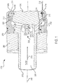
- ECG 210 may comprise flow distributor 220, inner electrode 240, outer electrode 245, insulator 250, and end housing 260.
- End housing 260 may be in contact with insulator 250.
- Insulator 250 may be in contact with flow distributor 220.
- Insulator 250 may be in contact with outer electrode 245.
- Flow distributor 220 may be in contact with inner electrode 240.
- Flow distributor 220 may be in contact with end housing 260.
- inner electrode 240 and outer electrode 245 define an annular flow path 214.
- ECG 210 may comprise flow distributor 220 for directing a fluid flow 212 from an inlet 222 to annular flow path 214.
- Flow distributor 220 may comprise a plurality of holes 230 configured to direct fluid flow 212 from inlet 222 to annular flow path 214.
- plurality of holes 230 may route fluid flow 212 from inner surface 226 of flow distributor 220 to outer surface 228 of flow distributor 220.
- ECG 210 may operate by converting dissolved chloride ions in fluid flow 212 into available chlorine.
- fluid flow 212 may comprise salt water which may be chlorinated via ECG 210 to prevent fouling in a system which uses fluid flow 212.
- flow distributor 220 may comprise between six and twelve holes 230, and, in various embodiments, flow distributor 220 may comprise nine holes 230. However, flow distributor 220 may comprise any number of holes 230 depending on the size of flow distributor 220 and the desired flow characteristics of fluid flow 212.
- plurality of holes 230 may comprise, for example, first hole 231 and second hole 232.
- First hole 231 may be circumferentially adjacent to second hole 232.
- flow distributor 220 may comprise an inner surface 226 and an outer surface 228.
- Flow distributor 220 may comprise a centerline axis 292.
- Inner surface 226 may comprise a radially inner surface.
- Outer surface 228 may comprise a radially outer surface.
- First hole 231 and second hole 232 may extend between inner surface 226 and outer surface 228.
- First hole 231 may comprise a first inlet 233.
- Second hole 232 may comprise a second inlet 234.
- First inlet 233 may be axially offset from second inlet 234.
- first inlet 233 may be spaced from second inlet 234. Stated differently, first inlet 233 may be separated from second inlet 234 by a distance 294. In this manner, first inlet 233 does not intersect with second inlet 234. In this manner, first inlet 233 does not share a common edge with second inlet 234.
- first hole 231 may comprise a circular geometry.
- second hole 232 may comprise a circular geometry.
- the diameter of first hole 231 may be equal to the diameter of second hole 232.
- ECG 210 may receive an axial load 216 at inner electrode 240.
- axial load 216 may comprise a gravitational or acceleration load, in response to a shock event for example.
- Axial load 216 may be transmitted from inner electrode 240, through flow distributor 220, to end housing 260, via load path 218.
- inner electrode 240, flow distributor 220, and end housing 260 may define load path 218.
- Axial load 216 may be transmitted around plurality of holes 230.
- Flow distributor 220 may be compressed between end housing 260 and inner electrode 240. Because the inlets of plurality of holes 230 are axially offset, material of flow distributor 220 may be increased within axial plane 202 compared to a typical flow distributor. In this regard, peak stress may be reduced in flow distributor 220.
- flow distributor 220 of FIG. 1 may be similar to flow distributor 320.
- Flow distributor 320 may comprise a centerline axis 392.
- Flow distributor 320 may comprise a head portion 370 and a tube portion 372.
- Tube portion 372 may extend from head portion 370 along centerline axis 392.
- Tube portion 372 may comprise a cylindrical geometry.
- Head portion 370 may comprise a cylindrical geometry.
- Head portion 370 may comprise an outer surface 328.
- Outer surface 328 may comprise a radially outer surface.
- Outer surface 328 may comprise a mating face 376 configured to receive an inner electrode.
- Outer surface 328 may comprise a first channel 377 circumferentially disposed in outer surface 328 and configured to receive a seal.
- Outer surface 328 may comprise a second channel 378 circumferentially disposed in outer surface 328 and configured to receive a seal.
- Flow distributor 320 may comprise an inner surface 326.
- Inner surface 326 may be located radially inward from outer surface 328 with respect to centerline axis 392.
- Tube portion 372 may be at least partially defined by inner surface 326.
- Tube portion may comprise an inlet 322 configured to receive a fluid flow.
- flow distributor 320 may comprise a first plurality of holes 332 extending from inner surface 326 to outer surface 328.
- Flow distributor 320 may comprise a second plurality of holes 334 extending from inner surface 326 to outer surface 328.
- first plurality of holes 332 may be oriented at a first angle ⁇ with respect to centerline axis 392.
- FIG. 3 illustrates centerline axis 494 of hole 432 oriented at first angle ⁇ with respect to centerline axis 392.
- Second plurality of holes 334 may be oriented at a second angle ⁇ with respect to centerline axis 392.
- FIG. 3 illustrates centerline axis 494 of hole 432 oriented at first angle ⁇ with respect to centerline axis 392.
- Second plurality of holes 334 may be oriented at a second angle ⁇ with respect to centerline axis 392.
- first angle ⁇ may be less than second angle ⁇ .
- flow distributor 320 may comprise any number of holes oriented at any number of angles with respect to centerline axis 392 such that each of the holes does not intersect at inner surface 326.
- plurality of holes 330 may each comprise an inlet (e.g., inlet 436) defined at inner surface 326 and an outlet (e.g., outlet 438) defined at outer surface 328.
- each outlet 438 may be axially aligned with the axially adjacent outlets.
- first plurality of holes 332 may extend from a first axial plane 302 at outer surface 328 to a second axial plane 304 at inner surface 326.
- second plurality of holes 334 may extend from first axial plane 302 at outer surface 328 to a third axial plane 306 at inner surface 326.
- first axial plane 302 is axially spaced from second axial plane 304.
- first axial plane 302 is axially spaced from third axial plane 306.
- second axial plane 304 is axially spaced from third axial plane 306.
- a flow distributor 220 may comprise an insulating material.
- flow distributor 220 may be made from fiberglass for example.
- flow distributor 220 may comprise any suitable material including composites, polymers, etc.
- inner electrode 240 and outer electrode 245, as described herein, may comprise titanium.
Landscapes
- Chemical & Material Sciences (AREA)
- Organic Chemistry (AREA)
- Engineering & Computer Science (AREA)
- Chemical Kinetics & Catalysis (AREA)
- Electrochemistry (AREA)
- Metallurgy (AREA)
- Materials Engineering (AREA)
- Life Sciences & Earth Sciences (AREA)
- Water Supply & Treatment (AREA)
- Environmental & Geological Engineering (AREA)
- Hydrology & Water Resources (AREA)
- General Chemical & Material Sciences (AREA)
- Inorganic Chemistry (AREA)
- Physical Or Chemical Processes And Apparatus (AREA)
- Feeding, Discharge, Calcimining, Fusing, And Gas-Generation Devices (AREA)
- Electrolytic Production Of Non-Metals, Compounds, Apparatuses Therefor (AREA)
- Iron Core Of Rotating Electric Machines (AREA)
- Vaporization, Distillation, Condensation, Sublimation, And Cold Traps (AREA)
- Hybrid Cells (AREA)
Priority Applications (1)
| Application Number | Priority Date | Filing Date | Title |
|---|---|---|---|
| EP23184275.8A EP4242351A3 (de) | 2017-05-05 | 2018-02-05 | Strömungsverteiler |
Applications Claiming Priority (1)
| Application Number | Priority Date | Filing Date | Title |
|---|---|---|---|
| US15/588,060 US10240243B2 (en) | 2017-05-05 | 2017-05-05 | Flow distributor hole pattern |
Related Child Applications (1)
| Application Number | Title | Priority Date | Filing Date |
|---|---|---|---|
| EP23184275.8A Division EP4242351A3 (de) | 2017-05-05 | 2018-02-05 | Strömungsverteiler |
Publications (3)
| Publication Number | Publication Date |
|---|---|
| EP3398910A2 true EP3398910A2 (de) | 2018-11-07 |
| EP3398910A3 EP3398910A3 (de) | 2019-02-13 |
| EP3398910B1 EP3398910B1 (de) | 2023-08-09 |
Family
ID=61163573
Family Applications (2)
| Application Number | Title | Priority Date | Filing Date |
|---|---|---|---|
| EP18155118.5A Active EP3398910B1 (de) | 2017-05-05 | 2018-02-05 | Strömungsverteiler |
| EP23184275.8A Pending EP4242351A3 (de) | 2017-05-05 | 2018-02-05 | Strömungsverteiler |
Family Applications After (1)
| Application Number | Title | Priority Date | Filing Date |
|---|---|---|---|
| EP23184275.8A Pending EP4242351A3 (de) | 2017-05-05 | 2018-02-05 | Strömungsverteiler |
Country Status (2)
| Country | Link |
|---|---|
| US (1) | US10240243B2 (de) |
| EP (2) | EP3398910B1 (de) |
Families Citing this family (1)
| Publication number | Priority date | Publication date | Assignee | Title |
|---|---|---|---|---|
| US11717839B2 (en) * | 2020-11-25 | 2023-08-08 | Kidde Technologies, Inc. | Nozzle configurations to create a vortex of fire suppression agent |
Family Cites Families (9)
| Publication number | Priority date | Publication date | Assignee | Title |
|---|---|---|---|---|
| GB1331251A (en) * | 1970-12-22 | 1973-09-26 | Cjb Developments Ltd | Electrochemical processes |
| US6471873B1 (en) | 2000-01-26 | 2002-10-29 | Bernard Greenberg | Electrolytic process and apparatus for purifying contaminated aqueous solutions and method for using same to remediate soil |
| US20040256118A1 (en) * | 2002-11-28 | 2004-12-23 | Kidde-Fenwal Inc. | Fire extinguisher discharge method and apparatus |
| US20070221584A1 (en) * | 2005-06-27 | 2007-09-27 | Ruprecht John C | Whole house water filter |
| WO2010071622A1 (en) | 2008-12-18 | 2010-06-24 | Utc Fire & Security Corporation | Atomizing nozzle for a fire suppression system |
| US8557122B2 (en) * | 2010-03-05 | 2013-10-15 | Tohoku University | Ballast water treatment equipment, a ballast water detoxifying treatment system using the same, and a method for treating the ballast water |
| FR2961714B1 (fr) | 2010-06-29 | 2015-02-20 | Aqua Tools | Module de filtration d'eau |
| US11046595B2 (en) * | 2014-05-23 | 2021-06-29 | Hydrus Technology Pty. Ltd. | Electrochemical treatment methods |
| TWM535598U (zh) | 2016-08-10 | 2017-01-21 | 國立成功大學 | 水流分配器及流體化床裝置 |
-
2017
- 2017-05-05 US US15/588,060 patent/US10240243B2/en active Active
-
2018
- 2018-02-05 EP EP18155118.5A patent/EP3398910B1/de active Active
- 2018-02-05 EP EP23184275.8A patent/EP4242351A3/de active Pending
Non-Patent Citations (1)
| Title |
|---|
| None |
Also Published As
| Publication number | Publication date |
|---|---|
| EP3398910A3 (de) | 2019-02-13 |
| EP4242351A3 (de) | 2023-09-27 |
| EP4242351A2 (de) | 2023-09-13 |
| US20180320276A1 (en) | 2018-11-08 |
| EP3398910B1 (de) | 2023-08-09 |
| US10240243B2 (en) | 2019-03-26 |
Similar Documents
| Publication | Publication Date | Title |
|---|---|---|
| EP2655949B1 (de) | Fluidstecker mit einer schlauchschneideklemme | |
| EP3728925A1 (de) | Doppelrohrfitting und montage eines doppelrohrfittings | |
| CN107709744B (zh) | 包括排气壳体和下游旋转对称部件的组件 | |
| SE429993B (sv) | Anordning for astadkommande av ett friktionsforband | |
| JP2019066036A5 (de) | ||
| US11898662B2 (en) | High performance aramid braided hose | |
| EP4242351A2 (de) | Strömungsverteiler | |
| US20090126819A1 (en) | Cladding for elongate flexible member | |
| US10128643B2 (en) | Loom assembly providing improved electrical isolation | |
| US20170030499A1 (en) | Bulkhead connector assembly | |
| WO2018071882A1 (en) | Connector assemblies for connecting tubulars and related methods | |
| EP2325594A2 (de) | Schalldämpfer | |
| RU2602939C2 (ru) | Уплотнительная шайба | |
| US9915377B2 (en) | Underwater pipe assembly and method of assembling underwater pipes | |
| US10359140B2 (en) | Feedback bulkhead connector assembly | |
| JP2018529933A (ja) | エンコーダシャフトを駆動シャフトに固定するためのエンコーダ固定装置、及び、固定方法 | |
| GB2521272A (en) | Cable housing connector | |
| EP3486435B1 (de) | Sicherungsverbindung mit gefenstertem sicherungsstift | |
| AU2023249184B2 (en) | Frame for use subsea | |
| JP2020172929A (ja) | 燃料分配装置、ガスタービンエンジン、および取り付け方法 | |
| EP3789295A1 (de) | Flugzeug und verfahren zum abfangen eines flugziels | |
| EP3306031B1 (de) | Ermüdungslebensdauerverlängerer | |
| US11248638B2 (en) | Pole section for assembly into a pole for cleaning elevated windows and/or gutters | |
| CN104901062A (zh) | 尾部附件及使用该尾部附件的连接器 | |
| JP2014081161A (ja) | 鏡板および貯湯タンク |
Legal Events
| Date | Code | Title | Description |
|---|---|---|---|
| PUAI | Public reference made under article 153(3) epc to a published international application that has entered the european phase |
Free format text: ORIGINAL CODE: 0009012 |
|
| STAA | Information on the status of an ep patent application or granted ep patent |
Free format text: STATUS: THE APPLICATION HAS BEEN PUBLISHED |
|
| AK | Designated contracting states |
Kind code of ref document: A2 Designated state(s): AL AT BE BG CH CY CZ DE DK EE ES FI FR GB GR HR HU IE IS IT LI LT LU LV MC MK MT NL NO PL PT RO RS SE SI SK SM TR |
|
| AX | Request for extension of the european patent |
Extension state: BA ME |
|
| PUAL | Search report despatched |
Free format text: ORIGINAL CODE: 0009013 |
|
| AK | Designated contracting states |
Kind code of ref document: A3 Designated state(s): AL AT BE BG CH CY CZ DE DK EE ES FI FR GB GR HR HU IE IS IT LI LT LU LV MC MK MT NL NO PL PT RO RS SE SI SK SM TR |
|
| AX | Request for extension of the european patent |
Extension state: BA ME |
|
| RIC1 | Information provided on ipc code assigned before grant |
Ipc: C02F 1/00 20060101AFI20190109BHEP Ipc: C02F 1/467 20060101ALN20190109BHEP Ipc: C25B 1/26 20060101ALN20190109BHEP |
|
| STAA | Information on the status of an ep patent application or granted ep patent |
Free format text: STATUS: REQUEST FOR EXAMINATION WAS MADE |
|
| 17P | Request for examination filed |
Effective date: 20190806 |
|
| RBV | Designated contracting states (corrected) |
Designated state(s): AL AT BE BG CH CY CZ DE DK EE ES FI FR GB GR HR HU IE IS IT LI LT LU LV MC MK MT NL NO PL PT RO RS SE SI SK SM TR |
|
| STAA | Information on the status of an ep patent application or granted ep patent |
Free format text: STATUS: EXAMINATION IS IN PROGRESS |
|
| 17Q | First examination report despatched |
Effective date: 20200430 |
|
| GRAP | Despatch of communication of intention to grant a patent |
Free format text: ORIGINAL CODE: EPIDOSNIGR1 |
|
| STAA | Information on the status of an ep patent application or granted ep patent |
Free format text: STATUS: GRANT OF PATENT IS INTENDED |
|
| RIC1 | Information provided on ipc code assigned before grant |
Ipc: C25B 1/26 20060101ALN20230209BHEP Ipc: C02F 1/467 20060101ALN20230209BHEP Ipc: C02F 1/00 20060101AFI20230209BHEP |
|
| RIC1 | Information provided on ipc code assigned before grant |
Ipc: C25B 1/26 20060101ALN20230216BHEP Ipc: C02F 1/467 20060101ALN20230216BHEP Ipc: C02F 1/00 20060101AFI20230216BHEP |
|
| RIC1 | Information provided on ipc code assigned before grant |
Ipc: C25B 1/26 20060101ALN20230221BHEP Ipc: C02F 1/467 20060101ALN20230221BHEP Ipc: C02F 1/00 20060101AFI20230221BHEP |
|
| INTG | Intention to grant announced |
Effective date: 20230309 |
|
| GRAS | Grant fee paid |
Free format text: ORIGINAL CODE: EPIDOSNIGR3 |
|
| GRAA | (expected) grant |
Free format text: ORIGINAL CODE: 0009210 |
|
| STAA | Information on the status of an ep patent application or granted ep patent |
Free format text: STATUS: THE PATENT HAS BEEN GRANTED |
|
| AK | Designated contracting states |
Kind code of ref document: B1 Designated state(s): AL AT BE BG CH CY CZ DE DK EE ES FI FR GB GR HR HU IE IS IT LI LT LU LV MC MK MT NL NO PL PT RO RS SE SI SK SM TR |
|
| REG | Reference to a national code |
Ref country code: GB Ref legal event code: FG4D |
|
| REG | Reference to a national code |
Ref country code: CH Ref legal event code: EP |
|
| REG | Reference to a national code |
Ref country code: IE Ref legal event code: FG4D |
|
| REG | Reference to a national code |
Ref country code: DE Ref legal event code: R096 Ref document number: 602018054869 Country of ref document: DE |
|
| REG | Reference to a national code |
Ref country code: LT Ref legal event code: MG9D |
|
| REG | Reference to a national code |
Ref country code: NL Ref legal event code: MP Effective date: 20230809 |
|
| REG | Reference to a national code |
Ref country code: AT Ref legal event code: MK05 Ref document number: 1597364 Country of ref document: AT Kind code of ref document: T Effective date: 20230809 |
|
| PG25 | Lapsed in a contracting state [announced via postgrant information from national office to epo] |
Ref country code: GR Free format text: LAPSE BECAUSE OF FAILURE TO SUBMIT A TRANSLATION OF THE DESCRIPTION OR TO PAY THE FEE WITHIN THE PRESCRIBED TIME-LIMIT Effective date: 20231110 |
|
| PG25 | Lapsed in a contracting state [announced via postgrant information from national office to epo] |
Ref country code: IS Free format text: LAPSE BECAUSE OF FAILURE TO SUBMIT A TRANSLATION OF THE DESCRIPTION OR TO PAY THE FEE WITHIN THE PRESCRIBED TIME-LIMIT Effective date: 20231209 |
|
| PG25 | Lapsed in a contracting state [announced via postgrant information from national office to epo] |
Ref country code: SE Free format text: LAPSE BECAUSE OF FAILURE TO SUBMIT A TRANSLATION OF THE DESCRIPTION OR TO PAY THE FEE WITHIN THE PRESCRIBED TIME-LIMIT Effective date: 20230809 Ref country code: RS Free format text: LAPSE BECAUSE OF FAILURE TO SUBMIT A TRANSLATION OF THE DESCRIPTION OR TO PAY THE FEE WITHIN THE PRESCRIBED TIME-LIMIT Effective date: 20230809 Ref country code: PT Free format text: LAPSE BECAUSE OF FAILURE TO SUBMIT A TRANSLATION OF THE DESCRIPTION OR TO PAY THE FEE WITHIN THE PRESCRIBED TIME-LIMIT Effective date: 20231211 Ref country code: NO Free format text: LAPSE BECAUSE OF FAILURE TO SUBMIT A TRANSLATION OF THE DESCRIPTION OR TO PAY THE FEE WITHIN THE PRESCRIBED TIME-LIMIT Effective date: 20231109 Ref country code: NL Free format text: LAPSE BECAUSE OF FAILURE TO SUBMIT A TRANSLATION OF THE DESCRIPTION OR TO PAY THE FEE WITHIN THE PRESCRIBED TIME-LIMIT Effective date: 20230809 Ref country code: LV Free format text: LAPSE BECAUSE OF FAILURE TO SUBMIT A TRANSLATION OF THE DESCRIPTION OR TO PAY THE FEE WITHIN THE PRESCRIBED TIME-LIMIT Effective date: 20230809 Ref country code: LT Free format text: LAPSE BECAUSE OF FAILURE TO SUBMIT A TRANSLATION OF THE DESCRIPTION OR TO PAY THE FEE WITHIN THE PRESCRIBED TIME-LIMIT Effective date: 20230809 Ref country code: IS Free format text: LAPSE BECAUSE OF FAILURE TO SUBMIT A TRANSLATION OF THE DESCRIPTION OR TO PAY THE FEE WITHIN THE PRESCRIBED TIME-LIMIT Effective date: 20231209 Ref country code: HR Free format text: LAPSE BECAUSE OF FAILURE TO SUBMIT A TRANSLATION OF THE DESCRIPTION OR TO PAY THE FEE WITHIN THE PRESCRIBED TIME-LIMIT Effective date: 20230809 Ref country code: GR Free format text: LAPSE BECAUSE OF FAILURE TO SUBMIT A TRANSLATION OF THE DESCRIPTION OR TO PAY THE FEE WITHIN THE PRESCRIBED TIME-LIMIT Effective date: 20231110 Ref country code: FI Free format text: LAPSE BECAUSE OF FAILURE TO SUBMIT A TRANSLATION OF THE DESCRIPTION OR TO PAY THE FEE WITHIN THE PRESCRIBED TIME-LIMIT Effective date: 20230809 Ref country code: AT Free format text: LAPSE BECAUSE OF FAILURE TO SUBMIT A TRANSLATION OF THE DESCRIPTION OR TO PAY THE FEE WITHIN THE PRESCRIBED TIME-LIMIT Effective date: 20230809 |
|
| PG25 | Lapsed in a contracting state [announced via postgrant information from national office to epo] |
Ref country code: PL Free format text: LAPSE BECAUSE OF FAILURE TO SUBMIT A TRANSLATION OF THE DESCRIPTION OR TO PAY THE FEE WITHIN THE PRESCRIBED TIME-LIMIT Effective date: 20230809 |
|
| PG25 | Lapsed in a contracting state [announced via postgrant information from national office to epo] |
Ref country code: ES Free format text: LAPSE BECAUSE OF FAILURE TO SUBMIT A TRANSLATION OF THE DESCRIPTION OR TO PAY THE FEE WITHIN THE PRESCRIBED TIME-LIMIT Effective date: 20230809 |
|
| PG25 | Lapsed in a contracting state [announced via postgrant information from national office to epo] |
Ref country code: SM Free format text: LAPSE BECAUSE OF FAILURE TO SUBMIT A TRANSLATION OF THE DESCRIPTION OR TO PAY THE FEE WITHIN THE PRESCRIBED TIME-LIMIT Effective date: 20230809 Ref country code: RO Free format text: LAPSE BECAUSE OF FAILURE TO SUBMIT A TRANSLATION OF THE DESCRIPTION OR TO PAY THE FEE WITHIN THE PRESCRIBED TIME-LIMIT Effective date: 20230809 Ref country code: ES Free format text: LAPSE BECAUSE OF FAILURE TO SUBMIT A TRANSLATION OF THE DESCRIPTION OR TO PAY THE FEE WITHIN THE PRESCRIBED TIME-LIMIT Effective date: 20230809 Ref country code: EE Free format text: LAPSE BECAUSE OF FAILURE TO SUBMIT A TRANSLATION OF THE DESCRIPTION OR TO PAY THE FEE WITHIN THE PRESCRIBED TIME-LIMIT Effective date: 20230809 Ref country code: DK Free format text: LAPSE BECAUSE OF FAILURE TO SUBMIT A TRANSLATION OF THE DESCRIPTION OR TO PAY THE FEE WITHIN THE PRESCRIBED TIME-LIMIT Effective date: 20230809 Ref country code: CZ Free format text: LAPSE BECAUSE OF FAILURE TO SUBMIT A TRANSLATION OF THE DESCRIPTION OR TO PAY THE FEE WITHIN THE PRESCRIBED TIME-LIMIT Effective date: 20230809 Ref country code: SK Free format text: LAPSE BECAUSE OF FAILURE TO SUBMIT A TRANSLATION OF THE DESCRIPTION OR TO PAY THE FEE WITHIN THE PRESCRIBED TIME-LIMIT Effective date: 20230809 |
|
| REG | Reference to a national code |
Ref country code: DE Ref legal event code: R097 Ref document number: 602018054869 Country of ref document: DE |
|
| PG25 | Lapsed in a contracting state [announced via postgrant information from national office to epo] |
Ref country code: IT Free format text: LAPSE BECAUSE OF FAILURE TO SUBMIT A TRANSLATION OF THE DESCRIPTION OR TO PAY THE FEE WITHIN THE PRESCRIBED TIME-LIMIT Effective date: 20230809 |
|
| PLBE | No opposition filed within time limit |
Free format text: ORIGINAL CODE: 0009261 |
|
| STAA | Information on the status of an ep patent application or granted ep patent |
Free format text: STATUS: NO OPPOSITION FILED WITHIN TIME LIMIT |
|
| 26N | No opposition filed |
Effective date: 20240513 |
|
| PG25 | Lapsed in a contracting state [announced via postgrant information from national office to epo] |
Ref country code: SI Free format text: LAPSE BECAUSE OF FAILURE TO SUBMIT A TRANSLATION OF THE DESCRIPTION OR TO PAY THE FEE WITHIN THE PRESCRIBED TIME-LIMIT Effective date: 20230809 |
|
| PG25 | Lapsed in a contracting state [announced via postgrant information from national office to epo] |
Ref country code: MC Free format text: LAPSE BECAUSE OF FAILURE TO SUBMIT A TRANSLATION OF THE DESCRIPTION OR TO PAY THE FEE WITHIN THE PRESCRIBED TIME-LIMIT Effective date: 20230809 |
|
| REG | Reference to a national code |
Ref country code: CH Ref legal event code: PL |
|
| PG25 | Lapsed in a contracting state [announced via postgrant information from national office to epo] |
Ref country code: LU Free format text: LAPSE BECAUSE OF NON-PAYMENT OF DUE FEES Effective date: 20240205 |
|
| PG25 | Lapsed in a contracting state [announced via postgrant information from national office to epo] |
Ref country code: CH Free format text: LAPSE BECAUSE OF NON-PAYMENT OF DUE FEES Effective date: 20240229 |
|
| PG25 | Lapsed in a contracting state [announced via postgrant information from national office to epo] |
Ref country code: LU Free format text: LAPSE BECAUSE OF NON-PAYMENT OF DUE FEES Effective date: 20240205 Ref country code: CH Free format text: LAPSE BECAUSE OF NON-PAYMENT OF DUE FEES Effective date: 20240229 |
|
| PG25 | Lapsed in a contracting state [announced via postgrant information from national office to epo] |
Ref country code: BG Free format text: LAPSE BECAUSE OF FAILURE TO SUBMIT A TRANSLATION OF THE DESCRIPTION OR TO PAY THE FEE WITHIN THE PRESCRIBED TIME-LIMIT Effective date: 20230809 |
|
| PG25 | Lapsed in a contracting state [announced via postgrant information from national office to epo] |
Ref country code: BG Free format text: LAPSE BECAUSE OF FAILURE TO SUBMIT A TRANSLATION OF THE DESCRIPTION OR TO PAY THE FEE WITHIN THE PRESCRIBED TIME-LIMIT Effective date: 20230809 |
|
| REG | Reference to a national code |
Ref country code: BE Ref legal event code: MM Effective date: 20240229 |
|
| PG25 | Lapsed in a contracting state [announced via postgrant information from national office to epo] |
Ref country code: BE Free format text: LAPSE BECAUSE OF NON-PAYMENT OF DUE FEES Effective date: 20240229 |
|
| PG25 | Lapsed in a contracting state [announced via postgrant information from national office to epo] |
Ref country code: FR Free format text: LAPSE BECAUSE OF NON-PAYMENT OF DUE FEES Effective date: 20240229 |
|
| PG25 | Lapsed in a contracting state [announced via postgrant information from national office to epo] |
Ref country code: IE Free format text: LAPSE BECAUSE OF NON-PAYMENT OF DUE FEES Effective date: 20240205 |
|
| PG25 | Lapsed in a contracting state [announced via postgrant information from national office to epo] |
Ref country code: IE Free format text: LAPSE BECAUSE OF NON-PAYMENT OF DUE FEES Effective date: 20240205 Ref country code: FR Free format text: LAPSE BECAUSE OF NON-PAYMENT OF DUE FEES Effective date: 20240229 Ref country code: BE Free format text: LAPSE BECAUSE OF NON-PAYMENT OF DUE FEES Effective date: 20240229 |
|
| PG25 | Lapsed in a contracting state [announced via postgrant information from national office to epo] |
Ref country code: CY Free format text: LAPSE BECAUSE OF FAILURE TO SUBMIT A TRANSLATION OF THE DESCRIPTION OR TO PAY THE FEE WITHIN THE PRESCRIBED TIME-LIMIT; INVALID AB INITIO Effective date: 20180205 |
|
| PG25 | Lapsed in a contracting state [announced via postgrant information from national office to epo] |
Ref country code: HU Free format text: LAPSE BECAUSE OF FAILURE TO SUBMIT A TRANSLATION OF THE DESCRIPTION OR TO PAY THE FEE WITHIN THE PRESCRIBED TIME-LIMIT; INVALID AB INITIO Effective date: 20180205 |
|
| PG25 | Lapsed in a contracting state [announced via postgrant information from national office to epo] |
Ref country code: TR Free format text: LAPSE BECAUSE OF FAILURE TO SUBMIT A TRANSLATION OF THE DESCRIPTION OR TO PAY THE FEE WITHIN THE PRESCRIBED TIME-LIMIT Effective date: 20230809 |
|
| P01 | Opt-out of the competence of the unified patent court (upc) registered |
Free format text: CASE NUMBER: UPC_APP_0017173_3398910/2025 Effective date: 20251211 |
|
| PGFP | Annual fee paid to national office [announced via postgrant information from national office to epo] |
Ref country code: GB Payment date: 20260121 Year of fee payment: 9 |
|
| PGFP | Annual fee paid to national office [announced via postgrant information from national office to epo] |
Ref country code: DE Payment date: 20260121 Year of fee payment: 9 |