EP3398859A1 - Füllrohr zum füllen von ventilsäcken - Google Patents
Füllrohr zum füllen von ventilsäcken Download PDFInfo
- Publication number
- EP3398859A1 EP3398859A1 EP17169511.7A EP17169511A EP3398859A1 EP 3398859 A1 EP3398859 A1 EP 3398859A1 EP 17169511 A EP17169511 A EP 17169511A EP 3398859 A1 EP3398859 A1 EP 3398859A1
- Authority
- EP
- European Patent Office
- Prior art keywords
- filling
- channel
- opening
- pipe according
- filling tube
- Prior art date
- Legal status (The legal status is an assumption and is not a legal conclusion. Google has not performed a legal analysis and makes no representation as to the accuracy of the status listed.)
- Granted
Links
Images


Classifications
-
- B—PERFORMING OPERATIONS; TRANSPORTING
- B65—CONVEYING; PACKING; STORING; HANDLING THIN OR FILAMENTARY MATERIAL
- B65B—MACHINES, APPARATUS OR DEVICES FOR, OR METHODS OF, PACKAGING ARTICLES OR MATERIALS; UNPACKING
- B65B1/00—Packaging fluent solid material, e.g. powders, granular or loose fibrous material, loose masses of small articles, in individual containers or receptacles, e.g. bags, sacks, boxes, cartons, cans, or jars
- B65B1/04—Methods of, or means for, filling the material into the containers or receptacles
- B65B1/18—Methods of, or means for, filling the material into the containers or receptacles for filling valve-bags
-
- B—PERFORMING OPERATIONS; TRANSPORTING
- B65—CONVEYING; PACKING; STORING; HANDLING THIN OR FILAMENTARY MATERIAL
- B65D—CONTAINERS FOR STORAGE OR TRANSPORT OF ARTICLES OR MATERIALS, e.g. BAGS, BARRELS, BOTTLES, BOXES, CANS, CARTONS, CRATES, DRUMS, JARS, TANKS, HOPPERS, FORWARDING CONTAINERS; ACCESSORIES, CLOSURES, OR FITTINGS THEREFOR; PACKAGING ELEMENTS; PACKAGES
- B65D31/00—Bags or like containers made of paper and having structural provision for thickness of contents
- B65D31/14—Valve bags, i.e. with valves for filling
-
- B—PERFORMING OPERATIONS; TRANSPORTING
- B65—CONVEYING; PACKING; STORING; HANDLING THIN OR FILAMENTARY MATERIAL
- B65B—MACHINES, APPARATUS OR DEVICES FOR, OR METHODS OF, PACKAGING ARTICLES OR MATERIALS; UNPACKING
- B65B1/00—Packaging fluent solid material, e.g. powders, granular or loose fibrous material, loose masses of small articles, in individual containers or receptacles, e.g. bags, sacks, boxes, cartons, cans, or jars
- B65B1/28—Controlling escape of air or dust from containers or receptacles during filling
-
- B—PERFORMING OPERATIONS; TRANSPORTING
- B65—CONVEYING; PACKING; STORING; HANDLING THIN OR FILAMENTARY MATERIAL
- B65B—MACHINES, APPARATUS OR DEVICES FOR, OR METHODS OF, PACKAGING ARTICLES OR MATERIALS; UNPACKING
- B65B31/00—Packaging articles or materials under special atmospheric or gaseous conditions; Adding propellants to aerosol containers
- B65B31/04—Evacuating, pressurising or gasifying filled containers or wrappers by means of nozzles through which air or other gas, e.g. an inert gas, is withdrawn or supplied
- B65B31/044—Evacuating, pressurising or gasifying filled containers or wrappers by means of nozzles through which air or other gas, e.g. an inert gas, is withdrawn or supplied the nozzles being combined with a filling device
-
- B—PERFORMING OPERATIONS; TRANSPORTING
- B65—CONVEYING; PACKING; STORING; HANDLING THIN OR FILAMENTARY MATERIAL
- B65D—CONTAINERS FOR STORAGE OR TRANSPORT OF ARTICLES OR MATERIALS, e.g. BAGS, BARRELS, BOTTLES, BOXES, CANS, CARTONS, CRATES, DRUMS, JARS, TANKS, HOPPERS, FORWARDING CONTAINERS; ACCESSORIES, CLOSURES, OR FITTINGS THEREFOR; PACKAGING ELEMENTS; PACKAGES
- B65D33/00—Details of, or accessories for, sacks or bags
-
- B—PERFORMING OPERATIONS; TRANSPORTING
- B65—CONVEYING; PACKING; STORING; HANDLING THIN OR FILAMENTARY MATERIAL
- B65B—MACHINES, APPARATUS OR DEVICES FOR, OR METHODS OF, PACKAGING ARTICLES OR MATERIALS; UNPACKING
- B65B2210/00—Specific aspects of the packaging machine
- B65B2210/10—Means for removing bridges formed by the material or article, e.g. anti-clogging devices
-
- B—PERFORMING OPERATIONS; TRANSPORTING
- B65—CONVEYING; PACKING; STORING; HANDLING THIN OR FILAMENTARY MATERIAL
- B65B—MACHINES, APPARATUS OR DEVICES FOR, OR METHODS OF, PACKAGING ARTICLES OR MATERIALS; UNPACKING
- B65B39/00—Nozzles, funnels or guides for introducing articles or materials into containers or wrappers
- B65B39/02—Expansible or contractible nozzles, funnels, or guides
Definitions
- the invention relates to a filling tube for filling and venting valve bags, which has a front end with a filling opening and a rear end for fixing to a filling machine, with a filling channel enclosed by a filling tube wall.
- a filling tube is made of DE 44 26 080 C2 known and welded in the embodiments described there of several parts of metal. Adjacent to the filling channel further channels are provided, which serve the blowing out of the filling tube or the suction of air from the valve bag to be filled.
- This known construction is complicated, expensive and allows only a relatively simple design of the channels.
- the object of the invention is to improve a known filling tube to the effect that the production can be made easier and cheaper and an optimal design of the channels is easier.
- the filling tube is made by an additive manufacturing process and has at least one channel which is at least partially embedded in the Greepand and each starting from a arranged at the rear end connection opening in the direction of the front end runs.
- the at least one channel may include a vent channel extending to a vent opening adjacent to the fill port leading to an exterior of the fill tube, and / or a vent passage extending to a vent opening in a central region of the fill tube and opening into the fill channel runs, and / or an inflation duct for inflating a Blähmanschette which extends to a arranged in a central region of the filling tube and leading to the outside of the filling tube inflation opening comprise.
- the channel or channels provided in the filling tube wall of a filler tube produced by an additive manufacturing process favorable design options for the course and the arrangement of the channels, while the inside of the filling tube wall, which forms the filling channel, smooth and in the Can be made substantially cylindrical.
- additive manufacturing process includes in particular processes such as electron beam melting (EBM) for processing metals, fused deposition modeling (FDM), for example ABS or polylactide being processed, laminated object modeling (LOM) in use of paper, plastics, ceramics or aluminum, Laser Engineered Net Shaping (LENS) or laser cladding (processing of metals), Multi Jet Modeling (MJM) for processing of thermoplastics, photopolymers, sand, metal or glass powder, polyamide casting, selective laser melting (SLM ) in the processing of metals, plastics or ceramics, laser-beam melts using thermoplastics such as polycarbonate, polyamides or polyvinylchloride or metals or ceramics, Space Puzzle Molding (SPM) in the processing of plastics, stereolithography (STL or SLA) in the processing of liquid duromers or elastomers, or finally bin jetting, where powder and granules are processed.
- EBM electron beam melting
- FDM fused deposition modeling
- LOM laminated object modeling
- the at least one channel is arranged verspringend, in other words in its course, starting from a arranged at the rear end connection opening in the direction of the front end undergoes at least one change of direction, wherein the change in direction in a circumferential direction and / or in a Radial direction with respect to a longitudinal axis of the filling tube can take place.
- the change in direction of the at least one channel from a course parallel to the longitudinal direction in a course at an angle to the longitudinal direction or in a direction transverse to the longitudinal direction be it in circumferential or Radial direction, done, or vice versa.
- Multiple changes of direction of the same channel are also possible.
- connection openings extend in a radial direction with respect to a longitudinal axis of the filling tube.
- a Boatrohrhalteplatte may be integrally formed with the filling tube, which is arranged in a plane perpendicular to a longitudinal axis of the filling tube.
- the vent channel may open at the front end into an annular channel embedded in the filling tube wall, which extends in the circumferential direction and is connected to the one or more vent openings.
- the filling tube wall can taper at the front end to a rounded Aufstecknase, from which the filling opening is cut out.
- a Sackleitsteg is arranged extending over the filling opening.
- the Sackleitsteg can extend from a tip portion of the Aufstecknase to a rear edge of the filling opening.
- the Sackleitsteg may be formed by a rib extending in a plane containing a longitudinal axis of the filling tube.
- a plurality of Sackleitstege may be formed, each emanating from the tip portion of the Aufstecknase and extending at an acute angle to the longitudinal axis of the conveying tube in the direction of the rear edge of the filling opening.
- an air supply passage embedded in the charge tube wall, which extends from the rear end to an air supply opening opening into the charge passage in an area between the rear end and the ventilation opening.
- the air supply channel may comprise a circumferentially extending annular channel portion and a plurality of longitudinally extending channel portions, wherein from each channel portion at least one air supply opening branches, which opens into the filling channel.
- Each channel section may have a longitudinally extending row of air supply openings opening into the filling channel.
- At least two channels for example the venting channel, the ventilation channel, the inflation channel and / or possibly the air supply channel extend at least in regions at different circumferential positions in the filling tube wall, or in other words are arranged side by side in the circumferential direction.
- two or more channels or channel sections extend at least in regions at matching circumferential positions in the filling tube wall and, in other words, are arranged one above the other in the radial direction and / or cross one another.
- At least one channel, the ventilation channel, the ventilation channel, the inflation channel and / or possibly the air supply channel extends or extend over its longitudinal extension at different radial positions in the filling tube wall.
- venting channel extends in the region of a Blähmanschettensitzes in a position with a smaller radius than at the rear end.
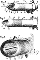
- a first embodiment of the invention is shown in different views in FIG Figure 1 to 7 shown.
- a filling tube 2 encloses a substantially cylindrical filling channel 4, which extends from a rear end 6 of the filling tube to a front end 8.
- the rear end 6 is used for fixing to a filling machine, not shown, wherein in the illustrated embodiment, a Guringhalteplatte 10 is formed integrally with the filling tube 2 at the rear end 6.
- mounting holes or slots 12 are formed for attachment to the filling machine.
- the entire filling tube is manufactured in an additive manufacturing process, for example by means of 3D printing.
- the filling tube 2 tapers to a rounded Aufstecknase 14 with a tip portion 16. Adjacent to the tip portion 16 is in the Aufstecknase 14 a filling opening 18 is formed or cut, in or through which the filling channel 4 opens.
- the filling channel 4 is enclosed by a filling tube wall 20, which essentially forms the filling tube and extends from the rear end 6 to the front end 8.
- the filling tube wall 20 merges to form the Aufstecknase 14, and at a lower end in operation of the Aufstecknase 14, the filling opening 18 is cut out.
- a Sackleitsteg 22 extends in a longitudinal direction 24 of the filling tube 2 via the filling opening 18, wherein the longitudinal direction 24 coincides with a Aufsteckcardi a valve sack on the filling tube 2.
- the Sackleitsteg 22 extends from the tip portion 16 of the Aufstecknase 14 to a rear edge of the filling opening 18 and is formed by an outer edge of a planar rib 26 which is integrally formed with the Artrohrwand 20.
- a Blähmanschettensitz 28 is formed, which comprises two spaced-apart, over the circumference of the Grezierwand 20 extending profiled projections 30.
- An annular inflatable sleeve 32 made of an elastic material can be airtightly inserted into the projections 30 around the filling tube wall 20 and inflated by means of air supply via an inflation passage 34 for fixing a valve bag.
- Cuff retaining rings 36 prevent the inflatable cuff 32 from disengaging from the projections 30.
- FIGS. 6 and 7 show the inflation channel 34 in its course from a connection opening 38 arranged at the rear end 6 to a blow-out opening 40 opening into the outside of the filling tube wall 20, through which air is pressed to inflate the inflation collar 32 into an annular gap 42 between the inflation collar 32 and the filling tube wall 20 can.
- two or more inflation channels 34 may be arranged at a mutual distance in the circumferential direction, which extend to two or more inflation openings 40 in the region of the inflation sleeve 32.
- FIGS. 4 and 5 illustrate the arrangement of a ventilation duct 46, which is embedded in the filling tube wall 20 between a connection opening 48 at the rear end 6 of the filling tube 2 and a vent opening 50 opening into the filling channel 4 runs.
- Compressed air can be introduced into the ventilation channel 46 via the connection opening 48, so that pulverulent material can be blown out of the filling channel 4 by a deliberate pressure surge at the end of the filling process without an uncontrolled after-trickling after removal of the valve sack from the filling tube 2.
- the ventilation channel 46 and the connection opening 48 and the ventilation opening 50 may be arranged in a center plane of the filling tube 2, which is defined by an extension plane of the rib 26, which forms the Sackleitsteg 22.
- a vent passage 52 extends between a connection opening 54 at the rear end 6 of the filling tube 2 and one or more vent openings 56 which open at the front end of the filling tube 2 in the vicinity of the filling opening 18 in the outside of the filling tube wall 20.
- two vents 56 are preferably provided, which are arranged on both sides of the filling opening 18.
- the vent passage 52 extends circumferentially offset with respect to the ventilation channel 46, for example offset by 20 ° to 30 ° in the circumferential direction.
- a circumferentially extending annular channel 53 connects, which leads to the two vents 56.
- two ventilation channels 52 could be provided, which are each arranged, for example, offset by 20 ° to 30 ° in the circumferential direction with respect to the ventilation channel 46.
- the one or more ventilation channels 52 serve to remove the air, which has passed into the valve bag together with the material during filling, from the bag.
- FIGS. 8 and 9 show in different views an air supply channel 60 which extends from a connection opening 62 at the rear end 6 of the filling tube 2 in the direction of the front end 8 and at a position in front of the inflation sleeve or before or the ventilation openings 50 of the ventilation channel 46 ends.
- the connection opening 62 connects partially over the Circumferentially extending annular channel portion 64, from which a plurality of air supply channels 60 extend in the longitudinal direction. From the or each air supply channel 60 branch off a number of air supply openings 66, which open into the filling channel 4.
- the purpose of the air supply channel (s) 60 is to feed air into the purge stream to loosen the material and allow for better filling.
Landscapes
- Engineering & Computer Science (AREA)
- Mechanical Engineering (AREA)
- Chemical & Material Sciences (AREA)
- Dispersion Chemistry (AREA)
- Basic Packing Technique (AREA)
- Pipe Accessories (AREA)
Abstract
Description
- Die Erfindung betrifft ein Füllrohr zum Füllen und Entlüften von Ventilsäcken, das ein vorderes Ende mit einer Füllöffnung und ein hinteres Ende zum Fixieren an einer Füllmaschine aufweist, mit einem von einer Füllrohrwand umschlossenen Füllkanal. Ein derartiges Füllrohr ist aus der
DE 44 26 080 C2 bekannt und in den dort beschriebenen Ausführungsformen aus mehreren Teilen aus Metall geschweißt. Benachbart zu dem Füllkanal sind weitere Kanäle vorgesehen, die dem Freiblasen des Füllrohrs bzw. dem Absaugen von Luft aus dem zu befüllenden Ventilsack dienen. Diese vorbekannte Bauweise ist aufwendig, teuer und lässt nur eine relativ einfache Gestaltung der Kanäle zu. - Die Aufgabe der Erfindung besteht darin, ein bekanntes Füllrohr dahingehend zu verbessern, dass die Fertigung einfacher und kostengünstiger erfolgen kann und eine optimale Gestaltung der Kanäle einfacher möglich ist.
- Diese Aufgabe wird bei einem gattungsgemäßen Füllrohr erfindungsgemäß dadurch gelöst, dass das Füllrohr mittels eines additiven Fertigungsverfahrens hergestellt ist und mindestens einen Kanal aufweist, der wenigstens bereichsweise in der Füllrohrwand eingebettet ist und jeweils ausgehend von einer an dem hinteren Ende angeordneten Anschlussöffnung in Richtung des vorderen Endes verläuft. Der mindestens eine Kanal kann einen Entlüftungskanal, der bis zu einer benachbart zu der Füllöffnung angeordneten, zu einer Außenseite des Füllrohrs führenden Entlüftungsöffnung verläuft, und/oder einen Belüftungskanal, der bis zu einer in einem mittleren Bereich des Füllrohrs angeordneten und in den Füllkanal mündenden Belüftungsöffnung verläuft, und/oder einen Aufblaskanal zum Aufblasen einer Blähmanschette, der bis zu einer in einem mittleren Bereich des Füllrohrs angeordneten und zur Außenseite des Füllrohrs führenden Aufblasöffnung verläuft, umfassen.
- Durch die erfindungsgemäße Maßnahme, den bzw. die Kanäle in der Füllrohrwand eines mittels eines additiven Fertigungsverfahrens hergestellten Füllrohrs eingebettet vorzusehen, ergeben sich günstige Gestaltungsmöglichkeiten für den Verlauf und die Anordnung der Kanäle, während die Innenseite der Füllrohrwand, die den Füllkanal bildet, glatt und im Wesentlichen zylindrisch ausgeführt sein kann.
- Im Rahmen der Erfindung fallen unter den Begriff additives Fertigungsverfahren (3D-Druck) insbesondere Verfahren wie Elektronenstrahlschmelzen (EBM) zum Verarbeiten von Metallen, Fused Deposition Modelling (FDM), wobei beispielsweise ABS oder Polylactide verarbeitet werden, Laminated Object Modelling (LOM) bei Verwendung von Papier, Kunststoffen, Keramik oder Aluminium, Laser Engineered Net Shaping (LENS) oder Laserauftragschweißen (Verarbeitung von Metallen), Multi Jet Modelling (MJM) bei Verarbeitung von Thermoplasten, Fotopolymeren, Sand, Metall- oder Glaspulver, Polyamidguss, selektives Laserschmelzen (SLM) bei Verarbeitung von Metallen, Kunststoffen oder Keramiken, Laserstrahlschmelzen, wobei Thermoplaste wie Polycarbonat, Polyamide oder Polyvenylchlorid oder aber Metalle oder Keramiken verarbeitet werden, Space Puzzle Molding (SPM) bei Verarbeitung von Kunststoffen, Stereolithografie (STL oder SLA) bei Verarbeitung von flüssigen Duromeren oder Elastomeren, oder schließlich Binder Jetting, wobei Pulver und Granulate verarbeitet werden.
- Es kann vorgesehen sein, dass der mindestens eine Kanal verspringend angeordnet ist, mit anderen Worten in seinem Verlauf ausgehend von einer an dem hinteren Ende angeordneten Anschlussöffnung in Richtung des vorderen Endes mindestens eine Richtungsänderung erfährt, wobei die Richtungsänderung in einer Umfangsrichtung und/oder in einer Radialrichtung bezüglich einer Längsachse des Füllrohrs erfolgen kann. Beispielsweise kann die Richtungsänderung des mindestens einen Kanals von einem Verlauf parallel zur Längsrichtung in einen Verlauf unter einem Winkel zur Längsrichtung oder in einen Verlauf quer zur Längsrichtung, sei es in Umfangs- oder Radialrichtung, erfolgen, oder umgekehrt. Mehrere Richtungsänderungen ein und desselben Kanals sind ebenfalls möglich.
- Es kann vorgesehen sein, dass die Anschlussöffnungen in einer radialen Richtung bezüglich einer Längsachse des Füllrohrs verlaufen.
- An dem hinteren Ende kann einstückig mit dem Füllrohr eine Füllrohrhalteplatte gebildet sein, die in einer Ebene senkrecht zu einer Längsachse des Füllrohrs angeordnet ist.
- Der Entlüftungskanal kann an dem vorderen Ende in einen in der Füllrohrwand eingebetteten Ringkanal münden, der sich in Umfangsrichtung erstreckt und mit der einen oder mit mehreren Entlüftungsöffnungen verbunden ist.
- Die Füllrohrwand kann an dem vorderen Ende zu einer abgerundeten Aufstecknase zulaufen, aus der die Füllöffnung ausgeschnitten ist.
- Zweckmäßigerweise kann vorgesehen sein, dass ein Sackleitsteg über die Füllöffnung hinweg verlaufend angeordnet ist. Der Sackleitsteg kann von einem Spitzenbereich der Aufstecknase bis zu einem hinteren Rand der Füllöffnung verlaufen. Der Sackleitsteg kann durch eine Rippe gebildet sein, die sich in einer eine Längsachse des Füllrohrs enthaltenden Ebene erstreckt.
- Alternativ können mehrere Sackleitstege gebildet sein, die jeweils von dem Spitzenbereich der Aufstecknase ausgehen und sich unter einem spitzen Winkel zur Längsachse des Förderrohrs in Richtung des hinteren Rands der Füllöffnung erstrecken.
- Es kann ein in der Füllrohrwand eingebetteter Luftzufuhrkanal vorgesehen sein, der von dem hinteren Ende bis zu einer in einem Bereich zwischen dem hinteren Ende und der Belüftungsöffnung in den Füllkanal mündenden Luftzufuhröffnung verläuft.
- Der Luftzufuhrkanal kann einen in Umfangsrichtung verlaufenden Ringkanalabschnitt und mehrere in Längsrichtung verlaufende Kanalabschnitte aufweisen, wobei von jedem Kanalabschnitt mindestens eine Luftzufuhröffnung abzweigt, die in den Füllkanal mündet. Jeder Kanalabschnitt kann eine in Längsrichtung verlaufende Reihe von Luftzufuhröffnungen, die in den Füllkanal münden, aufweisen.
- Zweckmäßigerweise ist vorgesehen, dass wenigstens zwei Kanäle, etwa der Entlüftungskanal, der Belüftungskanal, der Aufblaskanal und/oder ggf. der Luftzufuhrkanal zumindest bereichsweise an unterschiedlichen Umfangspositionen in der Füllrohrwand verlaufen, oder mit anderen Worten in Umfangsrichtung gesehen nebeneinander angeordnet sind. Es besteht die Möglichkeit, dass zwei oder mehr Kanäle oder Kanalabschnitte zumindest bereichsweise an übereinstimmenden Umfangspositionen in der Füllrohrwand verlaufen und mit anderen Worten bereichsweise in radialer Richtung gesehen übereinander angeordnet sind und/oder einander überkreuzen.
- Weiter kann vorgesehen sein, dass wenigstens ein Kanal, der Entlüftungskanal, der Belüftungskanal, der Aufblaskanal und/oder ggf. der Luftzufuhrkanal, über seine bzw. ihre Längserstreckung an unterschiedlichen Radialpositionen in der Füllrohrwand verläuft bzw. verlaufen.
- Es kann vorgesehen sein, dass der Entlüftungskanal im Bereich eines Blähmanschettensitzes in einer Position mit kleinerem Radius als am hinteren Ende verläuft.
- Weitere Vorteile und Merkmale der Erfindung ergeben sich aus der nachfolgenden Beschreibung eines Ausführungsbeispiels, wobei auf eine Zeichnung Bezug genommen ist, in der
- Fig. 1
- eine perspektivische Ansicht eines erfindungsgemäßen Füllrohrs schräg von vorn zeigt,
- Fig. 2
- eine Seitenansicht des Füllrohrs nach
Fig. 1 zeigt, - Fig. 3
- eine perspektivische Ansicht des vorderen Endes des Füllrohrs nach
Fig. 1 zeigt, - Fig. 4
- eine Längsschnittansicht eines Füllrohrs gemäß
Figur 1 zeigt, - Fig. 5
- eine schematische Schnittansicht entsprechend
Figur 4 zeigt, - Fig. 6
- eine Längsschnittansicht eines Füllrohrs nach
Figur 1 bis 3 an einer anderen Umfangsposition alsFigur 5 zeigt. - Fig. 7
- eine schematische Schnittansicht entsprechend
Fig. 6 zeigt, und - Fig. 8, 9
- eine Längsschnittansicht und eine Vorderansicht einer Variante des Ausführungsbeispiels nach
Figur 1 bis 7 zeigen. - Eine erste Ausführungsform der Erfindung ist in unterschiedlichen Ansichten in
Figur 1 bis 7 dargestellt. Ein Füllrohr 2 umschließt einen im Wesentlichen zylindrischen Füllkanal 4, der sich von einem hinteren Ende 6 des Füllrohrs bis zu einem vorderen Ende 8 erstreckt. Das hintere Ende 6 dient der Fixierung an einer nicht dargestellten Füllmaschine, wobei in dem dargestellten Ausführungsbeispiel eine Füllrohrhalteplatte 10 an dem hinteren Ende 6 einstückig mit dem Füllrohr 2 ausgebildet ist. An der Füllrohrhalteplatte 10 sind Befestigungslöcher oder -schlitze 12 zur Befestigung an der Füllmaschine ausgebildet. Das gesamte Füllrohr ist in einem additiven Fertigungsverfahren hergestellt, bspw. mittels 3D-Druck. - Am vorderen Ende 8 verjüngt sich das Füllrohr 2 zu einer abgerundeten Aufstecknase 14 mit einem Spitzenbereich 16. Benachbart zu dem Spitzenbereich 16 ist in der Aufstecknase 14 eine Füllöffnung 18 ausgebildet bzw. ausgeschnitten, in oder durch die der Füllkanal 4 mündet.
- Der Füllkanal 4 ist von einer Füllrohrwand 20 umschlossen, die im Wesentlichen das Füllrohr bildet und sich von dem hinteren Ende 6 bis zum vorderen Ende 8 erstreckt.
- Am vorderen Ende 8 läuft die Füllrohrwand 20 unter Bildung der Aufstecknase 14 zusammen, und an einem im Betrieb unteren Bereich der Aufstecknase 14 ist die Füllöffnung 18 ausgeschnitten.
- Ein Sackleitsteg 22 erstreckt sich in einer Längsrichtung 24 des Füllrohrs 2 über die Füllöffnung 18, wobei die Längsrichtung 24 mit einer Aufsteckrichtung eines Ventilsacks auf das Füllrohr 2 übereinstimmt. Der Sackleitsteg 22 verläuft von dem Spitzenbereich 16 der Aufstecknase 14 bis zu einem hinteren Rand der Füllöffnung 18 und ist durch eine Außenkante einer ebenen Rippe 26 gebildet, die einstückig mit der Füllrohrwand 20 ausgebildet ist.
- In einem mittleren Bereich des Füllrohrs, benachbart zu der Füllöffnung 18, ist auf einer Außenseite der Füllrohrwand 20 ein Blähmanschettensitz 28 ausgebildet, der zwei mit gegenseitigem Abstand angeordnete, über den Umfang der Füllrohrwand 20 verlaufende profilierte Vorsprünge 30 umfasst. Eine ringförmige Blähmanschette 32 aus einem elastischen Material kann um die Füllrohrwand 20 herum in die Vorsprünge 30 luftdicht eingesetzt werden und zur Fixierung eines Ventilsacks durch Luftzufuhr über einen Aufblaskanal 34 aufgebläht werden. Manschettenhalteringe 36 verhindern, dass sich die Blähmanschette 32 von den Vorsprüngen 30 löst.
- Die Schnittdarstellungen in
Figur 6 und 7 zeigen den Aufblaskanal 34 in seinem Verlauf von einer am hinteren Ende 6 angeordneten Anschlussöffnung 38 bis zu einer in der Außenseite der Füllrohrwand 20 mündenden Autblasöffnung 40, durch die Luft zum Aufblähen der Blähmanschette 32 in einen ringförmigen Zwischenraum 42 zwischen Blähmanschette 32 und Füllrohrwand 20 gedrückt werden kann. - Ausgehend von der Anschlussöffnung 38 können zwei oder auch mehr Aufblaskanäle 34 mit gegenseitigem Abstand in Umfangsrichtung angeordnet sein, die sich zu zwei oder mehr Aufblasöffnungen 40 im Bereich der Blähmanschette 32 erstrecken.
-
Figur 4 und 5 erläutern die Anordnung eines Belüftungskanals 46, der in der Füllrohrwand 20 eingebettet zwischen einer Anschlussöffnung 48 am hinteren Ende 6 des Füllrohrs 2 und einer in den Füllkanal 4 mündenden Belüftungsöffnung 50 verläuft. Über die Anschlussöffnung 48 ist Druckluft in den Belüftungskanal 46 einleitbar, so dass durch einen gezielten Druckstoß am Ende des Befüllungsvorgangs pulverförmiges Material aus dem Füllkanal 4 ausgeblasen werden kann, ohne dass es zu einem unkontrollierten Nachrieseln nach Abziehen des Ventilsacks von dem Füllrohr 2 kommt. - Der Belüftungskanal 46 sowie die Anschlussöffnung 48 und die Belüftungsöffnung 50 können in einer Mittelebene des Füllrohrs 2 angeordnet sein, die durch eine Erstreckungsebene der Rippe 26 festgelegt ist, die den Sackleitsteg 22 bildet.
- Ein Entlüftungskanal 52 verläuft zwischen einer Anschlussöffnung 54 am hinteren Ende 6 des Füllrohrs 2 und einer oder mehreren Entlüftungsöffnungen 56, die am vorderen Ende des Füllrohrs 2 in der Nähe der Füllöffnung 18 in der Außenseite der Füllrohrwand 20 münden. Wie
Figur 3 erkennen lässt, sind bevorzugt zwei Entlüftungsöffnungen 56 vorgesehen, die beiderseits der Füllöffnung 18 angeordnet sind. - Wie insbesondere
Figur 7 zeigt, verläuft der Entlüftungskanal 52 in Umfangsrichtung versetzt in Bezug auf den Belüftungskanal 46, beispielsweise um 20° bis 30° in Umfangsrichtung versetzt. Am vorderen Ende des Entlüftungskanals 52 schließt sich ein in Umfangsrichtung verlaufender ringförmiger Kanal 53 an, der bis zu den beiden Entlüftungsöffnungen 56 führt. Stattdessen könnten zwei Entlüftungskanäle 52 vorgesehen sein, die jeweils beispielsweise um 20° bis 30° in Umfangsrichtung versetzt in Bezug auf den Belüftungskanal 46 angeordnet sind. - Der oder die Entlüftungskanäle 52 dienen dazu, die Luft, die bei der Abfüllung zusammen mit dem Material in den Ventilsack gelangt ist, aus dem Sack abzuführen.
-
Figuren 8 und 9 zeigen in unterschiedlichen Ansichten einen Luftzufuhrkanal 60, der sich von einer Anschlussöffnung 62 am hinteren Ende 6 des Füllrohrs 2 in Richtung des vorderen Endes 8 erstreckt und an einer Position vor der Blähmanschette oder vor der oder den Belüftungsöffnungen 50 des Belüftungskanals 46 endet. In dem dargestellten Beispiel schließt sich an die Anschlussöffnung 62 ein teilweise über den Umfang verlaufender Ringkanalabschnitt 64 an, von dem mehrere Luftzufuhrkanäle 60 in Längsrichtung abgehen. Von dem bzw. jedem Luftzufuhrkanal 60 zweigen eine Reihe von Luftzufuhröffnungen 66 ab, die in den Füllkanal 4 münden. - Der Zweck des oder der Luftzufuhrkanäle 60 besteht darin, Luft in den Fülstrom einzufördern, um das Material aufzulockern und eine bessere Befüllung zu ermöglichen.
-
- 2
- Füllrohr
- 4
- Füllkanal
- 6
- hinteres Ende
- 8
- vorderes Ende
- 10
- Füllrohrhalteplatte
- 12
- Befestigungsschlitz
- 14
- Aufstecknase
- 16
- Spitzenbereich
- 18
- Füllöffnung
- 20
- Füllrohrwand
- 22
- Sackleitsteg
- 24
- Längsrichtung
- 26
- Rippe
- 28
- Blähmanschettensitz
- 30
- Vorsprung
- 32
- Blähmanschette
- 34
- Aufblaskanal
- 36
- Manschettenhaltering
- 38
- Anschlussöffnung
- 40
- Aufblasöffnung
- 42
- Zwischenraum
- 46
- Belüftungskanal
- 48
- Anschlussöffnung
- 50
- Belüftungsöffnung
- 52
- Entlüftungskanal
- 53
- ringförmiger Kanal
- 54
- Anschlussöffnung
- 56
- Entlüftungsöffnung
- 60
- Luftzufuhrkanal
- 62
- Anschlussöffnung
- 64
- Ringkanalabschnitt
- 66
- Luftzufuhröffnung
- 68
- Kanalabschnitt
Claims (17)
- Füllrohr (2) zum Füllen und Entlüften von Ventilsäcken, das ein vorderes Ende (8) mit einer Füllöffnung (18) und ein hinteres Ende (6) zum Fixieren an einer Füllmaschine aufweist, mit einem von einer Füllrohrwand (20) umschlossenen Füllkanal (4), wobei das Füllrohr (2) mittels eines additiven Fertigungsverfahrens hergestellt ist und mindestens einen Kanal (34, 46, 52, 60) aufweist, der wenigstens bereichsweise in der Füllrohrwand (20) eingebettet ist und jeweils ausgehend von einer an dem hinteren Ende (6) angeordneten Anschlussöffnung (38, 48, 54, 62) in Richtung des vorderen Endes (8) verläuft.
- Füllrohr nach Anspruch 1, wobei der mindestens eine Kanal (34, 46, 52, 60) einen Entlüftungskanal (52) umfasst, der bis zu einer benachbart zu der Füllöffnung (18) angeordneten, zu einer Außenseite des Füllrohrs (2) führenden Entlüftungsöffnung (56) verläuft.
- Füllrohr nach Anspruch 2, wobei der mindestens eine Kanal (34, 46, 52, 60) einen Belüftungskanal (46) umfasst, der bis zu einer in einem mittleren Bereich des Füllrohrs (2) angeordneten und in den Füllkanal (4) mündenden Belüftungsöffnung (50) verläuft.
- Füllrohr nach Anspruch 2 oder 3, wobei der mindestens eine Kanal (34, 46, 52, 60) einen Aufblaskanal (34) zum Aufblasen einer auf das Füllrohr (2) aufsetzbaren Blähmanschette (32) umfasst, der bis zu einer in einem mittleren Bereich des Füllrohrs (2) angeordneten und zur Außenseite des Füllrohrs (2) führenden Aufblasöffnung (40) verläuft.
- Füllrohr nach einem der vorangehenden Ansprüche, wobei der mindestens eine Kanal (34, 46, 52, 60) in seinem Verlauf ausgehend von einer an dem hinteren Ende (6) angeordneten Anschlussöffnung (38, 48, 54, 62) in Richtung des vorderen Endes (8) mindestens eine Richtungsänderung in einer Umfangs- und/oder Radialrichtung bezüglich einer Längsachse (24) erfährt.
- Füllrohr nach Anspruch 1 oder 2, dadurch gekennzeichnet, dass an dem hinteren Ende (6) einstückig mit dem Füllrohr (2) eine Füllrohrhalteplatte (10) gebildet ist, die in einer Ebene senkrecht zu einer Längsachse (24) des Füllrohrs (2) angeordnet ist.
- Füllrohr nach einem der vorangehenden Ansprüche, dadurch gekennzeichnet, dass der Entlüftungskanal (52) an dem vorderen Ende (8) in einen in der Füllrohrwand (20) eingebetteten Ringkanal (53) mündet, der sich in Umfangsrichtung erstreckt und mit der einen oder mit mehreren Entlüftungsöffnungen (56) verbunden ist.
- Füllrohr nach einem der vorangehenden Ansprüche, dadurch gekennzeichnet, dass die Füllrohrvvand (20) an dem vorderen Ende (8) zu einer abgerundeten Aufstecknase (14) zuläuft, aus der die Füllöffnung (18) ausgeschnitten ist.
- Füllrohr nach einem der vorangehenden Ansprüche, dadurch gekennzeichnet, dass ein Sackleitsteg (22) über die Füllöffnung (18) hinweg verlaufend angeordnet ist.
- Füllrohr nach Anspruch 9, dadurch gekennzeichnet, dass der Sackleitsteg (22) von einem Spitzenbereich (16) der Aufstecknase (14) bis zu einem hinteren Rand der Füllöffnung (18) verläuft.
- Füllrohr nach Anspruch 9 oder 10, dadurch gekennzeichnet, dass der Sackleitsteg (22) durch eine Rippe (26) gebildet ist, die sich in einer eine Längsachse (24) des Füllrohrs (2) enthaltenden Ebene erstreckt.
- Füllrohr nach einem der vorangehenden Ansprüche, dadurch gekennzeichnet, dass ein in der Füllrohrwand (20) eingebetteter Luftzufuhrkanal (60) vorgesehen ist, der von dem hinteren Ende (6) bis zu einer in einem Bereich zwischen dem hinteren Ende (6) und der Belüftungsöffnung (50) in den Füllkanal (4) mündenden Luftzufuhröffnung (66) verläuft.
- Füllrohr nach Anspruch 12, dadurch gekennzeichnet, dass der Luftzufuhrkanal (60) einen in Umfangsrichtung verlaufenden Ringkanalabschnitt (64) und mehrere in Längsrichtung (24) verlaufende Kanalabschnitte (68) aufweist, wobei von jedem Kanalabschnitt (68) mindestens eine Luftzufuhröffnung (66) abzweigt, die in den Füllkanal (4) mündet.
- Füllrohr nach Anspruch 13, dadurch gekennzeichnet, dass jeder Kanalabschnitt (68) eine in Längsrichtung (24) verlaufende Reihe von Luftzufuhröffnungen (66) aufweist, die in den Füllkanal (4) münden.
- Füllrohr nach einem der vorangehenden Ansprüche, dadurch gekennzeichnet, dass wenigstens zwei Kanäle, etwa der Entlüftungskanal (52), der Belüftungskanal (46), der Aufblaskanal (34) und/oder ggf. der Luftzufuhrkanal (60), zumindest bereichsweise an unterschiedlichen Umfangspositionen in der Füllrohrwand (20) verlaufen, oder in Umfangsrichtung gesehen nebeneinander angeordnet sind.
- Füllrohr nach einem der vorangehenden Ansprüche, dadurch gekennzeichnet, dass zwei oder mehr Kanäle (34, 46, 52, 60) oder Kanalabschnitte zumindest bereichsweise an übereinstimmenden Umfangspositionen in der Füllrohrwand (20) verlaufen und in radialer Richtung gesehen übereinander angeordnet sind und/oder einander überkreuzen.
- Füllrohr nach einem der vorangehenden Ansprüche, dadurch gekennzeichnet, dass der Entlüftungskanal (52) im Bereich eines Blähmanschettensitzes (28) in einer Position mit kleinerem Radius als am hinteren Ende (6) verläuft.
Priority Applications (3)
| Application Number | Priority Date | Filing Date | Title |
|---|---|---|---|
| EP17169511.7A EP3398859B1 (de) | 2017-05-04 | 2017-05-04 | Füllrohr zum füllen von ventilsäcken |
| ES17169511T ES2763083T3 (es) | 2017-05-04 | 2017-05-04 | Tubo de llenado para llenar sacos con válvula |
| CN201810419622.6A CN108792240B (zh) | 2017-05-04 | 2018-05-04 | 用于阀袋的填充和通气的填充管 |
Applications Claiming Priority (1)
| Application Number | Priority Date | Filing Date | Title |
|---|---|---|---|
| EP17169511.7A EP3398859B1 (de) | 2017-05-04 | 2017-05-04 | Füllrohr zum füllen von ventilsäcken |
Publications (2)
| Publication Number | Publication Date |
|---|---|
| EP3398859A1 true EP3398859A1 (de) | 2018-11-07 |
| EP3398859B1 EP3398859B1 (de) | 2019-09-25 |
Family
ID=58671462
Family Applications (1)
| Application Number | Title | Priority Date | Filing Date |
|---|---|---|---|
| EP17169511.7A Active EP3398859B1 (de) | 2017-05-04 | 2017-05-04 | Füllrohr zum füllen von ventilsäcken |
Country Status (3)
| Country | Link |
|---|---|
| EP (1) | EP3398859B1 (de) |
| CN (1) | CN108792240B (de) |
| ES (1) | ES2763083T3 (de) |
Cited By (1)
| Publication number | Priority date | Publication date | Assignee | Title |
|---|---|---|---|---|
| EP3523201A1 (de) * | 2016-10-10 | 2019-08-14 | Haver & Boecker OHG | Fülleinrichtung für eine packmaschine zum füllen von schüttgütern in gebinde |
Citations (8)
| Publication number | Priority date | Publication date | Assignee | Title |
|---|---|---|---|---|
| US2046761A (en) * | 1930-12-08 | 1936-07-07 | Andreas Arno | Bag filling spout |
| US2799465A (en) * | 1955-02-28 | 1957-07-16 | Clarence F Carter | Method and apparatus for filling receptacles |
| DE2717948A1 (de) * | 1977-04-22 | 1978-10-26 | Behn Verpackung Erwin | Ventilsackfuellvorrichtung fuer flugfaehiges fuellgut und verfahren zum betreiben der vorrichtung |
| CA1067050A (en) * | 1975-11-24 | 1979-11-27 | Black Products Company | Filling sleeve for valve bags |
| US4471820A (en) * | 1982-09-24 | 1984-09-18 | Lepisto J George | Valve bag filling nozzle |
| US4576210A (en) * | 1982-09-28 | 1986-03-18 | Champion International Corporation | Duck bill filler nozzle |
| EP0223216A1 (de) * | 1985-11-15 | 1987-05-27 | NATRONAG Gesellschaft für Verpackungssysteme mbH | Sackfüllmaschine |
| DE4426080A1 (de) * | 1993-07-24 | 1995-01-26 | Behn & Bates Maschf Gmbh | Füllvorrichtung zum Füllen und Entlüften von Ventilsäcken |
Family Cites Families (3)
| Publication number | Priority date | Publication date | Assignee | Title |
|---|---|---|---|---|
| US4003188A (en) * | 1975-11-24 | 1977-01-18 | Black Products Company | Valve bag filler, handling and sealing system |
| US4574851A (en) * | 1982-09-28 | 1986-03-11 | Champion International Corporation | Apparatus for filling a valve bag |
| US4498511A (en) * | 1982-09-28 | 1985-02-12 | Champion International Corporation | Apparatus for filling a valve bag |
-
2017
- 2017-05-04 ES ES17169511T patent/ES2763083T3/es active Active
- 2017-05-04 EP EP17169511.7A patent/EP3398859B1/de active Active
-
2018
- 2018-05-04 CN CN201810419622.6A patent/CN108792240B/zh active Active
Patent Citations (9)
| Publication number | Priority date | Publication date | Assignee | Title |
|---|---|---|---|---|
| US2046761A (en) * | 1930-12-08 | 1936-07-07 | Andreas Arno | Bag filling spout |
| US2799465A (en) * | 1955-02-28 | 1957-07-16 | Clarence F Carter | Method and apparatus for filling receptacles |
| CA1067050A (en) * | 1975-11-24 | 1979-11-27 | Black Products Company | Filling sleeve for valve bags |
| DE2717948A1 (de) * | 1977-04-22 | 1978-10-26 | Behn Verpackung Erwin | Ventilsackfuellvorrichtung fuer flugfaehiges fuellgut und verfahren zum betreiben der vorrichtung |
| US4471820A (en) * | 1982-09-24 | 1984-09-18 | Lepisto J George | Valve bag filling nozzle |
| US4576210A (en) * | 1982-09-28 | 1986-03-18 | Champion International Corporation | Duck bill filler nozzle |
| EP0223216A1 (de) * | 1985-11-15 | 1987-05-27 | NATRONAG Gesellschaft für Verpackungssysteme mbH | Sackfüllmaschine |
| DE4426080A1 (de) * | 1993-07-24 | 1995-01-26 | Behn & Bates Maschf Gmbh | Füllvorrichtung zum Füllen und Entlüften von Ventilsäcken |
| DE4426080C2 (de) | 1993-07-24 | 1996-09-19 | Behn & Bates Maschf Gmbh | Füllvorrichtung zum Füllen und Entlüften von Ventilsäcken |
Cited By (1)
| Publication number | Priority date | Publication date | Assignee | Title |
|---|---|---|---|---|
| EP3523201A1 (de) * | 2016-10-10 | 2019-08-14 | Haver & Boecker OHG | Fülleinrichtung für eine packmaschine zum füllen von schüttgütern in gebinde |
Also Published As
| Publication number | Publication date |
|---|---|
| CN108792240A (zh) | 2018-11-13 |
| CN108792240B (zh) | 2020-06-30 |
| EP3398859B1 (de) | 2019-09-25 |
| ES2763083T3 (es) | 2020-05-27 |
Similar Documents
| Publication | Publication Date | Title |
|---|---|---|
| EP2287027B1 (de) | Lüftungsdüse | |
| DE102013109716B4 (de) | Blasform, Blasformmaschine und Verfahren zur Umformung von Kunststoffvorformlingen zu Kunststoffbehältnissen mit Luftabführung | |
| EP2987630B1 (de) | Verfahren zur herstellung einer vulkanisierform für fahrzeugreifen und vulkanisierform für fahrzeugreifen | |
| EP1652644A1 (de) | Reifenvulkanisierform mit einer profilierten Formfläche aus gesintertem Material | |
| EP1042086B2 (de) | Verfahren zur herstellung eines bohrwerkzeugs f?r werkzeugmaschinen | |
| EP3398859B1 (de) | Füllrohr zum füllen von ventilsäcken | |
| WO2008028542A1 (de) | Verfahren zur herstellung einer vulkanisierform mit mehreren zu einer umfangsmässig geschlossenen form zusammenfügbaren profilsegmenten und vulkanisierform | |
| DE102010032618A1 (de) | Blasformwerkzeug | |
| EP2000659A2 (de) | Ansaugsystem | |
| DE102013226906A1 (de) | Mehrteilige Blasform für die Herstellung von geblasenen, aus Kunststoff bestehenden Werkstücken, sowie Verfahren zu deren Herstellung | |
| DE102013006594B4 (de) | Verfahren zur Herstellung eines Behälters aus thermoplastischem Kunststoff | |
| EP3322585B1 (de) | Vulkanisierform für fahrzeugreifen mit entlüftungsmitteln | |
| EP2418066B1 (de) | Spritzgießwerkzeug zur Herstellung eines hybriden Bauteils | |
| EP2240336B1 (de) | Verfahren zur herstellung eines luftkanals sowie ein entsprechender luftkanal | |
| EP1541320B1 (de) | Formwerkzeug zum Tiefziehen von Behältern aus thermoplastischem Kunststoff | |
| EP3147112A1 (de) | Herstellung von objekten mit faserverstärktem bereich | |
| EP2108783A2 (de) | Schneidkopfgrundkörper sowie Schneidkopf für eine Vortriebs- oder Gewinnungsmaschine und Verfahren zu deren Herstellung | |
| DE102013225280A1 (de) | Vulkanisierform für Fahrzeugreifen | |
| DE202012102651U1 (de) | Blasform für die Herstellung von Behältern mit Mündung | |
| EP1509342B2 (de) | Trockenreinigungsanlage für werkstücke | |
| EP1053858A2 (de) | Verfahren und Vorrichtung zum Herstellen von hohlkörperförmigen Artikeln aus thermoplastischem Kunststoff durch Saugblasen | |
| DE102005009045A1 (de) | Verfahren und Vorrichtung zum Einbringen von Dämmfasern in einen Schalldämpfer sowie Schalldämpfer mit eingebrachten Dämmfasern | |
| DE102005037308A1 (de) | Entlüftetes, mit einem Werkstoff befüllbares Werkzeug, insbesondere Spritzwerkzeug sowie Verfahren zur Entlüftung von Spritzwerkzeugen | |
| EP1590156B1 (de) | Entlüftungshilfe für ein spritzgusswerkzeug und verfahren zu deren herstellung | |
| DE102016104693B4 (de) | Schäumwerkzeug mit aufblasbarem End-/Anschluss-/Verschlussstück und Verfahren zum Abdichten eines Schäumwerkzeugs |
Legal Events
| Date | Code | Title | Description |
|---|---|---|---|
| PUAI | Public reference made under article 153(3) epc to a published international application that has entered the european phase |
Free format text: ORIGINAL CODE: 0009012 |
|
| STAA | Information on the status of an ep patent application or granted ep patent |
Free format text: STATUS: THE APPLICATION HAS BEEN PUBLISHED |
|
| AK | Designated contracting states |
Kind code of ref document: A1 Designated state(s): AL AT BE BG CH CY CZ DE DK EE ES FI FR GB GR HR HU IE IS IT LI LT LU LV MC MK MT NL NO PL PT RO RS SE SI SK SM TR |
|
| AX | Request for extension of the european patent |
Extension state: BA ME |
|
| STAA | Information on the status of an ep patent application or granted ep patent |
Free format text: STATUS: REQUEST FOR EXAMINATION WAS MADE |
|
| 17P | Request for examination filed |
Effective date: 20181217 |
|
| RBV | Designated contracting states (corrected) |
Designated state(s): AL AT BE BG CH CY CZ DE DK EE ES FI FR GB GR HR HU IE IS IT LI LT LU LV MC MK MT NL NO PL PT RO RS SE SI SK SM TR |
|
| GRAP | Despatch of communication of intention to grant a patent |
Free format text: ORIGINAL CODE: EPIDOSNIGR1 |
|
| STAA | Information on the status of an ep patent application or granted ep patent |
Free format text: STATUS: GRANT OF PATENT IS INTENDED |
|
| RIC1 | Information provided on ipc code assigned before grant |
Ipc: B65B 1/28 20060101ALI20190307BHEP Ipc: B65B 1/18 20060101AFI20190307BHEP Ipc: B65B 39/02 20060101ALN20190307BHEP Ipc: B65B 31/04 20060101ALI20190307BHEP |
|
| RIC1 | Information provided on ipc code assigned before grant |
Ipc: B65B 1/28 20060101ALI20190308BHEP Ipc: B65B 39/02 20060101ALN20190308BHEP Ipc: B65B 31/04 20060101ALI20190308BHEP Ipc: B65B 1/18 20060101AFI20190308BHEP |
|
| INTG | Intention to grant announced |
Effective date: 20190402 |
|
| GRAS | Grant fee paid |
Free format text: ORIGINAL CODE: EPIDOSNIGR3 |
|
| GRAA | (expected) grant |
Free format text: ORIGINAL CODE: 0009210 |
|
| STAA | Information on the status of an ep patent application or granted ep patent |
Free format text: STATUS: THE PATENT HAS BEEN GRANTED |
|
| AK | Designated contracting states |
Kind code of ref document: B1 Designated state(s): AL AT BE BG CH CY CZ DE DK EE ES FI FR GB GR HR HU IE IS IT LI LT LU LV MC MK MT NL NO PL PT RO RS SE SI SK SM TR |
|
| REG | Reference to a national code |
Ref country code: GB Ref legal event code: FG4D Free format text: NOT ENGLISH |
|
| REG | Reference to a national code |
Ref country code: CH Ref legal event code: EP |
|
| REG | Reference to a national code |
Ref country code: AT Ref legal event code: REF Ref document number: 1183603 Country of ref document: AT Kind code of ref document: T Effective date: 20191015 |
|
| REG | Reference to a national code |
Ref country code: IE Ref legal event code: FG4D Free format text: LANGUAGE OF EP DOCUMENT: GERMAN |
|
| REG | Reference to a national code |
Ref country code: DE Ref legal event code: R096 Ref document number: 502017002375 Country of ref document: DE |
|
| REG | Reference to a national code |
Ref country code: NL Ref legal event code: MP Effective date: 20190925 |
|
| PG25 | Lapsed in a contracting state [announced via postgrant information from national office to epo] |
Ref country code: BG Free format text: LAPSE BECAUSE OF FAILURE TO SUBMIT A TRANSLATION OF THE DESCRIPTION OR TO PAY THE FEE WITHIN THE PRESCRIBED TIME-LIMIT Effective date: 20191225 Ref country code: NO Free format text: LAPSE BECAUSE OF FAILURE TO SUBMIT A TRANSLATION OF THE DESCRIPTION OR TO PAY THE FEE WITHIN THE PRESCRIBED TIME-LIMIT Effective date: 20191225 Ref country code: SE Free format text: LAPSE BECAUSE OF FAILURE TO SUBMIT A TRANSLATION OF THE DESCRIPTION OR TO PAY THE FEE WITHIN THE PRESCRIBED TIME-LIMIT Effective date: 20190925 Ref country code: HR Free format text: LAPSE BECAUSE OF FAILURE TO SUBMIT A TRANSLATION OF THE DESCRIPTION OR TO PAY THE FEE WITHIN THE PRESCRIBED TIME-LIMIT Effective date: 20190925 Ref country code: LT Free format text: LAPSE BECAUSE OF FAILURE TO SUBMIT A TRANSLATION OF THE DESCRIPTION OR TO PAY THE FEE WITHIN THE PRESCRIBED TIME-LIMIT Effective date: 20190925 Ref country code: FI Free format text: LAPSE BECAUSE OF FAILURE TO SUBMIT A TRANSLATION OF THE DESCRIPTION OR TO PAY THE FEE WITHIN THE PRESCRIBED TIME-LIMIT Effective date: 20190925 |
|
| REG | Reference to a national code |
Ref country code: LT Ref legal event code: MG4D |
|
| PG25 | Lapsed in a contracting state [announced via postgrant information from national office to epo] |
Ref country code: GR Free format text: LAPSE BECAUSE OF FAILURE TO SUBMIT A TRANSLATION OF THE DESCRIPTION OR TO PAY THE FEE WITHIN THE PRESCRIBED TIME-LIMIT Effective date: 20191226 Ref country code: RS Free format text: LAPSE BECAUSE OF FAILURE TO SUBMIT A TRANSLATION OF THE DESCRIPTION OR TO PAY THE FEE WITHIN THE PRESCRIBED TIME-LIMIT Effective date: 20190925 Ref country code: LV Free format text: LAPSE BECAUSE OF FAILURE TO SUBMIT A TRANSLATION OF THE DESCRIPTION OR TO PAY THE FEE WITHIN THE PRESCRIBED TIME-LIMIT Effective date: 20190925 |
|
| PG25 | Lapsed in a contracting state [announced via postgrant information from national office to epo] |
Ref country code: AL Free format text: LAPSE BECAUSE OF FAILURE TO SUBMIT A TRANSLATION OF THE DESCRIPTION OR TO PAY THE FEE WITHIN THE PRESCRIBED TIME-LIMIT Effective date: 20190925 Ref country code: EE Free format text: LAPSE BECAUSE OF FAILURE TO SUBMIT A TRANSLATION OF THE DESCRIPTION OR TO PAY THE FEE WITHIN THE PRESCRIBED TIME-LIMIT Effective date: 20190925 Ref country code: RO Free format text: LAPSE BECAUSE OF FAILURE TO SUBMIT A TRANSLATION OF THE DESCRIPTION OR TO PAY THE FEE WITHIN THE PRESCRIBED TIME-LIMIT Effective date: 20190925 Ref country code: NL Free format text: LAPSE BECAUSE OF FAILURE TO SUBMIT A TRANSLATION OF THE DESCRIPTION OR TO PAY THE FEE WITHIN THE PRESCRIBED TIME-LIMIT Effective date: 20190925 Ref country code: PL Free format text: LAPSE BECAUSE OF FAILURE TO SUBMIT A TRANSLATION OF THE DESCRIPTION OR TO PAY THE FEE WITHIN THE PRESCRIBED TIME-LIMIT Effective date: 20190925 Ref country code: PT Free format text: LAPSE BECAUSE OF FAILURE TO SUBMIT A TRANSLATION OF THE DESCRIPTION OR TO PAY THE FEE WITHIN THE PRESCRIBED TIME-LIMIT Effective date: 20200127 |
|
| REG | Reference to a national code |
Ref country code: ES Ref legal event code: FG2A Ref document number: 2763083 Country of ref document: ES Kind code of ref document: T3 Effective date: 20200527 |
|
| PG25 | Lapsed in a contracting state [announced via postgrant information from national office to epo] |
Ref country code: IS Free format text: LAPSE BECAUSE OF FAILURE TO SUBMIT A TRANSLATION OF THE DESCRIPTION OR TO PAY THE FEE WITHIN THE PRESCRIBED TIME-LIMIT Effective date: 20200224 Ref country code: SK Free format text: LAPSE BECAUSE OF FAILURE TO SUBMIT A TRANSLATION OF THE DESCRIPTION OR TO PAY THE FEE WITHIN THE PRESCRIBED TIME-LIMIT Effective date: 20190925 Ref country code: CZ Free format text: LAPSE BECAUSE OF FAILURE TO SUBMIT A TRANSLATION OF THE DESCRIPTION OR TO PAY THE FEE WITHIN THE PRESCRIBED TIME-LIMIT Effective date: 20190925 Ref country code: SM Free format text: LAPSE BECAUSE OF FAILURE TO SUBMIT A TRANSLATION OF THE DESCRIPTION OR TO PAY THE FEE WITHIN THE PRESCRIBED TIME-LIMIT Effective date: 20190925 |
|
| REG | Reference to a national code |
Ref country code: DE Ref legal event code: R097 Ref document number: 502017002375 Country of ref document: DE |
|
| PG2D | Information on lapse in contracting state deleted |
Ref country code: IS |
|
| PG25 | Lapsed in a contracting state [announced via postgrant information from national office to epo] |
Ref country code: DK Free format text: LAPSE BECAUSE OF FAILURE TO SUBMIT A TRANSLATION OF THE DESCRIPTION OR TO PAY THE FEE WITHIN THE PRESCRIBED TIME-LIMIT Effective date: 20190925 Ref country code: IS Free format text: LAPSE BECAUSE OF FAILURE TO SUBMIT A TRANSLATION OF THE DESCRIPTION OR TO PAY THE FEE WITHIN THE PRESCRIBED TIME-LIMIT Effective date: 20200126 |
|
| PLBE | No opposition filed within time limit |
Free format text: ORIGINAL CODE: 0009261 |
|
| STAA | Information on the status of an ep patent application or granted ep patent |
Free format text: STATUS: NO OPPOSITION FILED WITHIN TIME LIMIT |
|
| 26N | No opposition filed |
Effective date: 20200626 |
|
| PG25 | Lapsed in a contracting state [announced via postgrant information from national office to epo] |
Ref country code: SI Free format text: LAPSE BECAUSE OF FAILURE TO SUBMIT A TRANSLATION OF THE DESCRIPTION OR TO PAY THE FEE WITHIN THE PRESCRIBED TIME-LIMIT Effective date: 20190925 |
|
| PG25 | Lapsed in a contracting state [announced via postgrant information from national office to epo] |
Ref country code: CH Free format text: LAPSE BECAUSE OF NON-PAYMENT OF DUE FEES Effective date: 20200531 Ref country code: LI Free format text: LAPSE BECAUSE OF NON-PAYMENT OF DUE FEES Effective date: 20200531 Ref country code: MC Free format text: LAPSE BECAUSE OF FAILURE TO SUBMIT A TRANSLATION OF THE DESCRIPTION OR TO PAY THE FEE WITHIN THE PRESCRIBED TIME-LIMIT Effective date: 20190925 |
|
| REG | Reference to a national code |
Ref country code: BE Ref legal event code: MM Effective date: 20200531 |
|
| PG25 | Lapsed in a contracting state [announced via postgrant information from national office to epo] |
Ref country code: LU Free format text: LAPSE BECAUSE OF NON-PAYMENT OF DUE FEES Effective date: 20200504 |
|
| PG25 | Lapsed in a contracting state [announced via postgrant information from national office to epo] |
Ref country code: IE Free format text: LAPSE BECAUSE OF NON-PAYMENT OF DUE FEES Effective date: 20200504 Ref country code: FR Free format text: LAPSE BECAUSE OF NON-PAYMENT OF DUE FEES Effective date: 20200531 |
|
| PG25 | Lapsed in a contracting state [announced via postgrant information from national office to epo] |
Ref country code: BE Free format text: LAPSE BECAUSE OF NON-PAYMENT OF DUE FEES Effective date: 20200531 |
|
| GBPC | Gb: european patent ceased through non-payment of renewal fee |
Effective date: 20210504 |
|
| PG25 | Lapsed in a contracting state [announced via postgrant information from national office to epo] |
Ref country code: GB Free format text: LAPSE BECAUSE OF NON-PAYMENT OF DUE FEES Effective date: 20210504 |
|
| PG25 | Lapsed in a contracting state [announced via postgrant information from national office to epo] |
Ref country code: TR Free format text: LAPSE BECAUSE OF FAILURE TO SUBMIT A TRANSLATION OF THE DESCRIPTION OR TO PAY THE FEE WITHIN THE PRESCRIBED TIME-LIMIT Effective date: 20190925 Ref country code: MT Free format text: LAPSE BECAUSE OF FAILURE TO SUBMIT A TRANSLATION OF THE DESCRIPTION OR TO PAY THE FEE WITHIN THE PRESCRIBED TIME-LIMIT Effective date: 20190925 Ref country code: CY Free format text: LAPSE BECAUSE OF FAILURE TO SUBMIT A TRANSLATION OF THE DESCRIPTION OR TO PAY THE FEE WITHIN THE PRESCRIBED TIME-LIMIT Effective date: 20190925 |
|
| PG25 | Lapsed in a contracting state [announced via postgrant information from national office to epo] |
Ref country code: MK Free format text: LAPSE BECAUSE OF FAILURE TO SUBMIT A TRANSLATION OF THE DESCRIPTION OR TO PAY THE FEE WITHIN THE PRESCRIBED TIME-LIMIT Effective date: 20190925 |
|
| P01 | Opt-out of the competence of the unified patent court (upc) registered |
Effective date: 20230411 |
|
| PGFP | Annual fee paid to national office [announced via postgrant information from national office to epo] |
Ref country code: DE Payment date: 20250519 Year of fee payment: 9 |
|
| PGFP | Annual fee paid to national office [announced via postgrant information from national office to epo] |
Ref country code: ES Payment date: 20250616 Year of fee payment: 9 |
|
| PGFP | Annual fee paid to national office [announced via postgrant information from national office to epo] |
Ref country code: IT Payment date: 20250530 Year of fee payment: 9 |
|
| PGFP | Annual fee paid to national office [announced via postgrant information from national office to epo] |
Ref country code: AT Payment date: 20250519 Year of fee payment: 9 |